

Instruction Bulletin
106-300NE Rev. 3.4
May 2000
World Class 3000
Oxygen Analyzer with HPS Heater
Power Supply Field Module
(for use with Existing Signal
Conditioning Electronics)
http://www.processanalytic.com

ESSENTIAL INSTRUCTIONS
READ THIS PAGE BEFORE PROCEEDING!
Rosemount Analytical designs, manufactures and tests its products to meet many national and
international standards. Because these instruments are sophisticated technical products, you
MUST properly install, use, and maintain them to ensure they continue to operate within their
normal specifications. The following instructions MUST be adhered to and integrated into your
safety program when installing, using, and maintaining Rosemount Analytical products. Failure to
follow the proper instructions may cause any one of the following situations to occur: Loss of life;
personal injury; property damage; damage to this instrument; and warranty invalidation.
• Read all instructions prior to installing, operating, and servicing the product.
• If you do not understand any of the instructions, contact your Rosemount Analytical repre-
sentative for clarification.
• Follow all warnings, cautions, and instructions marked on and supplied with the product.
• Inform and educate your personnel in the proper installation, operation, and mainte-
nance of the product.
• Install your equipment as specified in the Installation Instructions of the appropriate In-
struction Manual and per applicable local and national codes. Connect all products to the
proper electrical and pressure sources.
• To ensure proper performance, use qualified personnel to install, operate, update, program,
and maintain the product.
• When replacement parts are required, ensure that qualified people use replacement parts
specified by Rosemount. Unauthorized parts and procedures can affect the product’s performance, place the safe operation of your process at risk, and VOID YOUR WARRANTY.
Look-alike substitutions may result in fire, electrical hazards, or improper operation.
• Ensure that all equipment doors are closed and protective covers are in place, except
when maintenance is being performed by qualified persons, to prevent electrical shock
and personal injury.
The information contained in this document is subject to change without notice.
Emerson Process Management
Rosemount Analytical Inc.
Process Analytic Division
1201 N. Main St.
Orrville, OH 44667-0901
T (330) 682-9010
F (330) 684-4434
e-mail: gas.csc@EmersonProcess.com
http://www.processanalytic.com

HIGHLIGHTS OF CHANGES
Effective October, 1995 Rev. 3
Page Summary
Page 1-1 Updated art to reflect new probe configuration.
Page 1-3 Updated art to reflect new probe configuration.
Page 1-4 Updated art to reflect new probe configuration.
Page 2-1 Update installation procedure to include optional ceramic diffusor and
vee deflector.
Page 2-2 Updated art and dimensions to reflect new probe configurations.
Page 2-3 Updated art and dimensions to reflect new probe configurations.
Page 2-8 Updated art and dimensions to reflect new probe configurations.
Effective June, 1996 Rev. 3.1
Page Summary
Page 1-3 Added ambient air note.
Page 2-3 Updated Probe Installation, Figure 2-1, sheets 1 and 2 of 5.
Effective January, 1997 Rev. 3.2
Page Summary
Page iii Added "Safety instructions for the wiring and installation of this
apparatus".
Page 2-1 Added one WARNING to read new safety instructions and another
WARNING regarding protective covers and grounds.
Page 2-9 Added WARNING regarding protective covers and grounds and added
NOTE regarding HPS fuse locations and specifications.
Page 2-11 Added NOTE regarding HPS fuse specifications to Figure 2-7.
Page 3-1 Added WARNING regarding protective covers and grounds.
Page 4-1 Added WARNING regarding protective covers and grounds.
Page 7-1 Added fuses to index listing.

Effective May, 1997 Rev. 3.3
Page Summary
Page P-2 Added safety sheets.
Effective February, 1998 Rev. 3.4
Page Summary
Page 2-2 Figure 2-1. Changed calibration gas tube dimensions.

World Class 3000
PREFACE.........................................................................................................................P1
Definitions ......................................................................................................................... P1
Safety Instructions ........................................................................................................... P2
1-0 DESCRIPTION ................................................................................................................ 1-1
1-1 Component Checklist of Typical System (Package Contents) ........................................ 1-1
1-2 Overview.......................................................................................................................... 1-1
2-0 INSTALLATION .............................................................................................................. 2-1
2-1 Oxygen Analyzer (Probe) Installation .............................................................................. 2-1
2-2 Heater Power Supply Installation .................................................................................... 2-9
3-0 SETUP............................................................................................................................. 3-1
3-1 Overview.......................................................................................................................... 3-1
3-2 Models 218, 225, and 132 (Analog) Electronics Setup .................................................. 3-1
3-3 Model 218A Electronics Setup ....................................................................................... 3-2
3-4 Model TC200 VERITRIM Electronics Setup.................................................................... 3-3
3-5 Model 132 Digital Electronics Setup................................................................................ 3-4
Instruction Bulletin
106-300NE Rev. 3.4
May 2000
TABLE OF CONTENTS
4-0 TROUBLESHOOTING .................................................................................................... 4-1
4-1 Overview.......................................................................................................................... 4-1
4-2 System Troubleshooting.................................................................................................. 4-1
5-0 RETURN OF MATERIAL .............................................................................................. 5-1
6-0 APPENDICES ................................................................................................................. 6-1
7-0 INDEX.............................................................................................................................. 7-1
Rosemount Analytical Inc. A Division of Emerson Process Management i

Instruction Bulletin
106-300NE Rev. 3.4
May 2000
Figure 1-1. Typical System Package ....................................................................................... 1-1
Figure 1-2. Typical System Installation .................................................................................... 1-3
Figure 1-3. Typical System Wiring ........................................................................................... 1-4
Figure 2-1. Probe Installation ................................................................................................... 2-2
Figure 2-2. Orienting the Optional Vee Deflector..................................................................... 2-7
Figure 2-3. Outline of Heater Power Supply ............................................................................ 2-7
Figure 2-4. Electrical Installation of Heater Power Supply....................................................... 2-8
Figure 2-5. Heater Power Supply Wiring Connections ............................................................ 2-9
Figure 2-6. Jumper Selection Label ....................................................................................... 2-10
Figure 2-7. Jumpers on HPS Mother Board........................................................................... 2-11
Figure 3-1. Temperature Controller Card Calibration Points ................................................... 3-1
Figure 3-2. Main PCB (Model 218A) EPROM Replacement ................................................... 3-2
Figure 3-3. Main PCB (Model TC200) EPROM Replacement ................................................. 3-3
Figure 3-4. Main PCB (Model 132) EPROM Replacement...................................................... 3-4
World Class 3000
LIST OF ILLUSTRATIONS
ii Rosemount Analytical Inc. A Division of Emerson Process Management
World Class 3000
If the HPS 3000 and World Class 3000 probe are used with any of the following model
electronics; 218, 225, 218A, and TC200, read appropriate set point adjustment in Instruction
Bulletin (IB) 106-300NE to prevent damage to the World Class 3000 probe.
The purpose of this manual is to provide information concerning the components, functions, installation and maintenance of this particular oxygen analyzer.
Some sections may describe equipment not used in your configuration. The user should
become thoroughly familiar with the operation of this module before operating it. Read
this instruction manual completely.
Instruction Bulletin
106-300NE Rev. 3.4
May 2000
CAUTION
!
PREFACE
DEFINITIONS
The following definitions apply to WARNINGS, CAUTIONS, and NOTES found throughout this
publication.
Highlights an operation or maintenance
procedure, practice, condition, statement, etc. If not strictly observed, could
result in injury, death, or long-term
health hazards of personnel.
NOTE
Highlights an essential operating procedure,
condition, or statement.
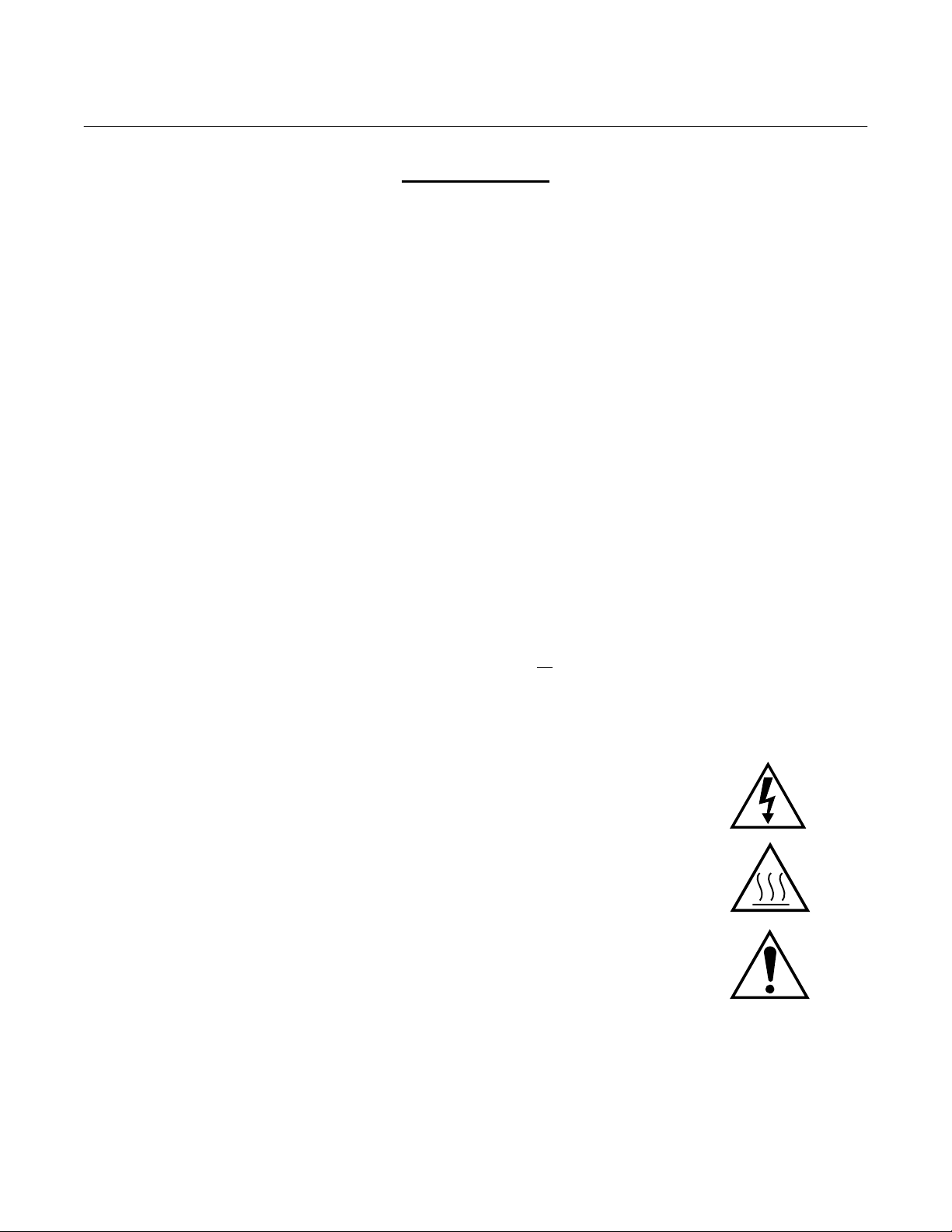
: EARTH (GROUND) TERMINAL
: PROTECTIVE CONDUCTOR TERMINAL
: RISK OF ELECTRICAL SHOCK
: WARNING: REFER TO INSTRUCTION BULLETIN
Highlights an operation or maintenance
procedure, practice, condition, statement, etc. If not strictly observed, could
result in damage to or destruction of
equipment, or loss of effectiveness.
NOTE TO USERS
The number in the lower right corner of each illustration in this publication is a manual illustration number. It is not a part number, and is not related to the illustration in any technical
manner.
Rosemount Analytical Inc. A Division of Emerson Process Management P-1
Instruction Bulletin
106-300NE Rev. 3.4
May 2000
FOR THE WIRING AND INSTALLATION
The following safety instructions apply specifically to all EU member states. They should
be strictly adhered to in order to assure compliance with the Low Voltage Directive. NonEU states should also comply with the following unless superseded by local or National
Standards.
1. Adequate earth connections should be made to all earthing points, internal and external,
where provided.
2. After installation or troubleshooting, all safety covers and safety grounds must be replaced.
The integrity of all earth terminals must be maintained at all times.
3. Mains supply cords should comply with the requirements of IEC227 or IEC245.
World Class 3000
IMPORTANT
SAFETY INSTRUCTIONS
OF THIS APPARATUS
4. All wiring shall be suitable for use in an ambient temperature of greater than 75°C.
5. All cable glands used should be of such internal dimensions as to provide adequate cable
anchorage.
6. To ensure safe operation of this equipment, connection to the mains supply should only be
made through a circuit breaker which will disconnect all circuits carrying conductors during a
fault situation. The circuit breaker may also include a mechanically operated isolating switch.
If not, then another means of disconnecting the equipment from the supply must be provided
and clearly marked as such. Circuit breakers or switches must comply with a recognized
standard such as IEC947. All wiring must conform with any local standards.
7. Where equipment or covers are marked with the symbol to the right, hazard-
ous voltages are likely to be present beneath. These covers should only be
removed when power is removed from the equipment — and then only by
trained service personnel.
8. Where equipment or covers are marked with the symbol to the right, there is a
danger from hot surfaces beneath. These covers should only be removed by
trained service personnel when power is removed from the equipment. Certain surfaces may remain hot to the touch.
9. Where equipment or covers are marked with the symbol to the right, refer to
the Operator Manual for instructions.
10. All graphical symbols used in this product are from one or more of the follow-
ing standards: EN61010-1, IEC417, and ISO3864.
P-2 Rosemount Analytical Inc. A Division of Emerson Process Management
World Class 3000
1
Instruction Bulletin
106-300NE Rev. 3.4
May 2000
SECTION 1
DESCRIPTION
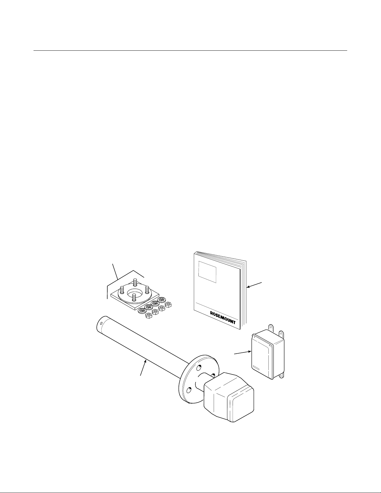
1-1 COMPONENT CHECKLIST OF TYPICAL
SYSTEM (PACKAGE CONTENTS)
A typical Rosemount World Class 3000 Oxygen
Analyzer with HPS 3000 Heater Power Supply
package should contain the items shown in
Figure 1-1. Record the Part Number, Serial
Number, and Order Number for each
component of your system in the table located
on the first page of this manual.
1-2 OVERVIEW
a. Scope
This Instruction Bulletin has been designed
to supply details needed to install, start up,
and troubleshoot the Rosemount World
Class 3000 Oxygen Analyzer with HPS
3000 Heater Power Supply Field Module.
4
The Heater Power Supply allows the
World Class 3000 Oxygen Analyzer (Probe)
to be interfaced to a number of different and
earlier model electronic packages. These
electronic packages are not covered in this
manual. For specific information concerning
calibration and operation of the system,
refer to the Instruction Bulletin applicable to
your electronics package.
b. System Description
The Rosemount Oxygen Analyzer (Probe) is
designed to measure the net concentration
of oxygen in an industrial process; i.e., the
oxygen remaining after all fuels have been
oxidized. The probe is permanently positioned within an exhaust duct or stack and
performs its task without the use of a sampling system.
1. Oxygen Analyzer (Probe)
2. Heater Power Supply
3. Instruction Bulletin
4. Mounting Adaptor Plate
with Mounting Hardware
and Gasket
3
2
1
19260001
Figure 1-1. Typical System Package
Rosemount Analytical Inc. A Division of Emerson Process Management Description 1-1

Instruction Bulletin
106-300NE Rev. 3.4
May 2000
World Class 3000
The equipment measures oxygen percentage by reading the voltage developed
across a heated electrochemical cell, which
consists of a small yttria-stabilized, zirconia
disc. Both sides of the disc are coated with
porous metal electrodes. When operated at
the proper temperature, the millivolt output
voltage of the cell is given by the following
Nernst equation:
EMF = KT log
10(P1/P2
) + C
Where:
1. P
is the partial pressure of the oxygen
2
in the measured gas on one side of the
cell,
2. P
is the partial pressure of the oxygen
1
in the reference gas on the other side,
3. T is the absolute temperature,
4. C is the cell constant,
5. K is an arithmetic constant.
NOTE
For best results, use clean, dry,
instrument air (20.95% oxygen) as a
reference gas.
When the cell is at operating temperature
and there are unequal oxygen concentrations across the cell, oxygen ions will travel
from the high partial pressure of oxygen
side to the low partial pressure side of the
cell. The resulting logarithmic output voltage
is approximately 50 mV per decade. Because the magnitude of the output is proportional to the logarithm of the inverse of
the sample of the oxygen partial pressure,
the output signal increases as the oxygen
concentration of the sample gas decreases.
This characteristic enables the oxygen
analyzer to provide exceptional sensitivity at
low oxygen concentrations.
Oxygen analyzer equipment measures net
oxygen concentration in the presence of all
the products of combustion, including water
vapor. Therefore, it may be considered an
analysis on a "wet" basis. In comparison
with older methods, such as the Orsat apparatus, which provides an analysis on a
"dry" gas basis, the "wet" analysis will, in
general, indicate a lower percentage of
oxygen. The difference will be proportional
to the water content of the sampled gas
stream.
c. System Configuration
The equipment discussed in this manual
consists of two major components; the oxygen analyzer (probe), and the heater power
supply.
Probes are available in five length options,
giving the user the flexibility to use an in situ
penetration appropriate to the size of the
stack or duct. The options on length are 18
inches (457 mm), 3 feet (0.91 m), 6 feet
(1.83 m), 9 feet (2.74 m), or 12 feet
(3.66 m).
The heater power supply (HPS) provides an
interface to the electronics package and
contains a transformer for supplying proper
voltage to the 44 Vac and 115 Vac probe
heaters. The enclosure has been designed
to meet NEMA 4X (IP56) specifications for
water tightness; an optional enclosure to
meet Class 1, Division 1, Group B (IP56)
explosion-proof is also available.
The oxygen analyzer is connected to the
HPS and electronics package using seven
wires housed within the connecting system
cable.
d. Features
1. Unique and patented cell protection
action that automatically protects
sensor cell when analyzer detects
reducing atmospheres.
2. Output voltage and sensitivity increase
as the oxygen concentration
decreases.
3. In situ, non-sampling analyzer.
4. Field replaceable cell.
5. Analyzer constructed of rugged 316
LSS for all wetted parts.
1-2 Description Rosemount Analytical Inc. A Division of Emerson Process Management
World Class 3000
1
Instruction Bulletin
106-300NE Rev. 3.4
May 2000
6. Suitable for use in temperatures up to
1300°F (700°C).
7. Heater power supply allows World
Class 3000 probe to be interfaced with
existing analog and 218A digital
electronic packages.
8. Optional explosion-proof HPS enclosure allows use in hazardous gas
areas.
e. Handling the Oxygen Analyzer
It is important that printed circuit
boards and integrated circuits are
handled only when adequate antistatic
precautions have been taken to
prevent possible equipment damage.
The oxygen analyzer is designed for
industrial application. Treat each
component of the system with care to
avoid physical damage. The probe
contains components made from
ceramics, which are susceptible to
shock when mishandled.
NOTE
Retain packaging in which the oxygen
analyzer arrived from the factory in
case any components are to be
shipped to another site. This packaging has been designed to protect the
product.
f. System Considerations
Prior to installation of your Rosemount
World Class 3000 Oxygen Analyzer with
Heater Power Supply Field Module, make
sure you have all of the components necessary to make the system installation. Ensure
all components are properly integrated to
make the system functional.
Once you have verified you have all the
components, select mounting locations and
determine how each component will be
placed in terms of available power supply,
ambient temperatures, environmental considerations, convenience, and serviceability.
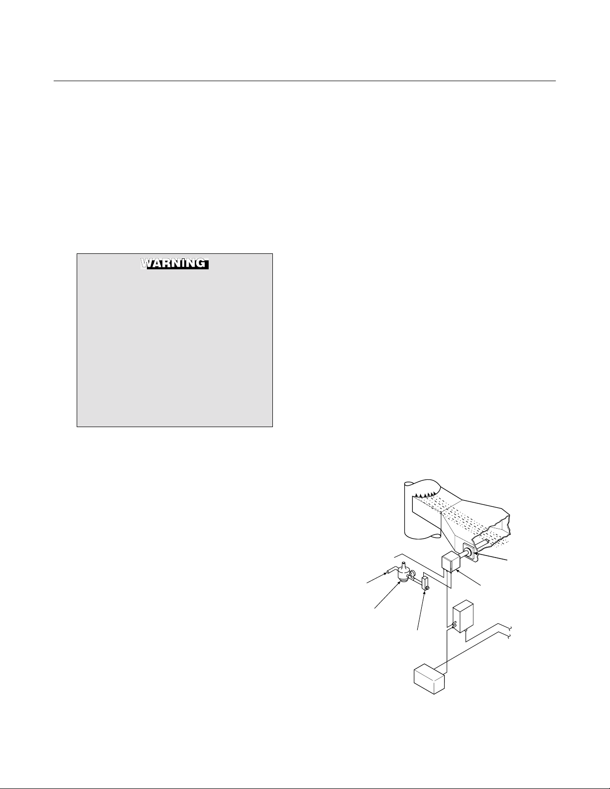
A typical installation is illustrated in Figure
1-2 and Figure 1-3.
After selecting the probe mounting location,
provision should be made for a platform
where the probe can be easily serviced.
The heater power supply can be located up
to 150 feet (45 m) cable distance from the
probe.
A source of instrument air is required at the
probe for reference gas use. Since the
probe is equipped with an in place calibration feature, provision should be made for
connecting test gas tanks to the oxygen
analyzer when the probe is to be calibrated.
NOTE
Ambient air is not recommended for
use as high test gas. An 8% O
ance in nitrogen is recommended for
high test gas.
If test gas bottles will be hooked up permanently, a check valve is required next to the
calibration fittings on the probe junction box.
This is to prevent breathing of calibration
gas line and subsequent flue gas condensation and corrosion. The check valve is in
addition to the stop valve in the test gas kit
or the solenoid valve in the multiprobe test
gas sequencer units.
GASES
STACK
CALIBRATION
INSTRUMENT
AIR SUPPLY
(REF. GAS)
GAS
PRESSURE
REGULATOR
ELECTRONICS
PACKAGE
FLOWMETER
Figure 1-2. Typical System Installation
bal-
2
DUCT
ADAPTER
PLATE
OXYGEN
ANALYZER
(PROBE)
HEATER POWER
SUPPLY
}
LINE
VOLTAGE
19260002
Rosemount Analytical Inc. A Division of Emerson Process Management Description 1-3
Instruction Bulletin
106-300NE Rev. 3.4
May 2000
World Class 3000
EXISTING
ELECTRONICS
YE
RD
OR
BL
BK
WH
GN
SHIELD
YE
RD
OR
BL
BK
WH
GN
SHIELD
SHIELD
*TRIAC RELAY
}
+
J9
PROBE
MV
}
+
J8
BL
OR
PROBE
MV
}
+
J3
BL
OR
STACK
TC
}
+
J2
}
+
PROBE
TC
}
+
YE
PROBE
+
SHIELD
PROBE
HEATER
STACK
TEMP
+
AD590
+
RD
TC
}
YE
RD
}
RH
BK
WH
}
}
SHIELD
GN
ANALOG
HEATER
}
BK WH
BK
GN
SHIELD
WH
(SEE PARAGRAPH 2.2.b)
MAINS
J1
LINE VOLTAGE
BY CUSTOMER
}
NL
HEATER POWER SUPPLY
*GATE VOLTAGE CONTROLLING TRIAC OUTPUT
STANDARD PROBE CABLE
6 M (20 FT)
HEATER
}
BL CELL -VE
OR CELL +VE
YE CHROMEL
RD ALUMEL
GN
BK
BK
1234567
BL
1-4 Description Rosemount Analytical Inc. A Division of Emerson Process Management
YE
RD
OR
PROBE HEAD
WIRING
GN
8
BK
WH
Figure 1-3. Typical System Wiring
12 M (40 FT)
18 M (60 FT)
PROBE
24 M (80 FT)
30 M (100 FT)
45 M (150 FT)
TEST GAS INPUT
AT 2-3 L/MIN
(4-7 SCFH)
CHECK
VALV E
REF. GAS SUPPLY
INPUT AIR AT
1 L/MIN (2 SCFH)
19260003
World Class 3000
2
Instruction Bulletin
106-300NE Rev. 3.4
May 2000
SECTION 2
INSTALLATION
2-1 OXYGEN ANALYZER (PROBE)
INSTALLATION
Before starting to install this equipment, read the "Safety instructions for
the wiring and installation of this apparatus" at the front of this Instruction
Bulletin. Failure to follow the safety
instructions could result in serious
injury or death.
Install all protective equipment covers
and safety ground leads after installation. Failure to install covers and
ground leads could result in serious
injury or death.
a. Selecting Location
1. The location of the probe in the stack
or flue is most important for maximum
accuracy in the oxygen analyzing process. The probe must be positioned so
that the gas it measures is representative of the process. Best results are
normally obtained if the probe is positioned near the center of the duct (40
to 60% insertion). A point too near the
edge or wall of the duct may not provide a representative sample because
of the possibility of gas stratification. In
addition, the sensing point should be
selected so that the process gas temperature falls within a range of 50° to
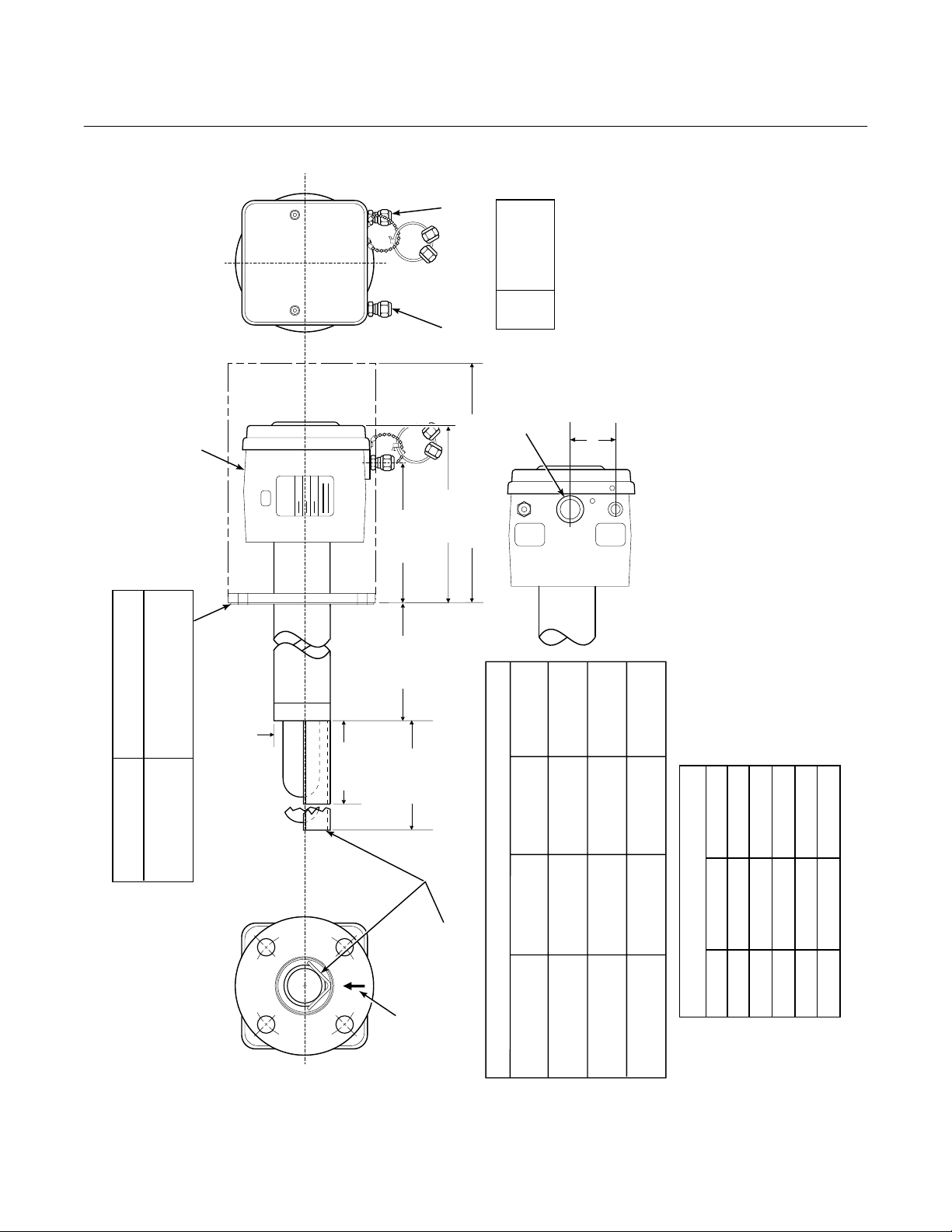
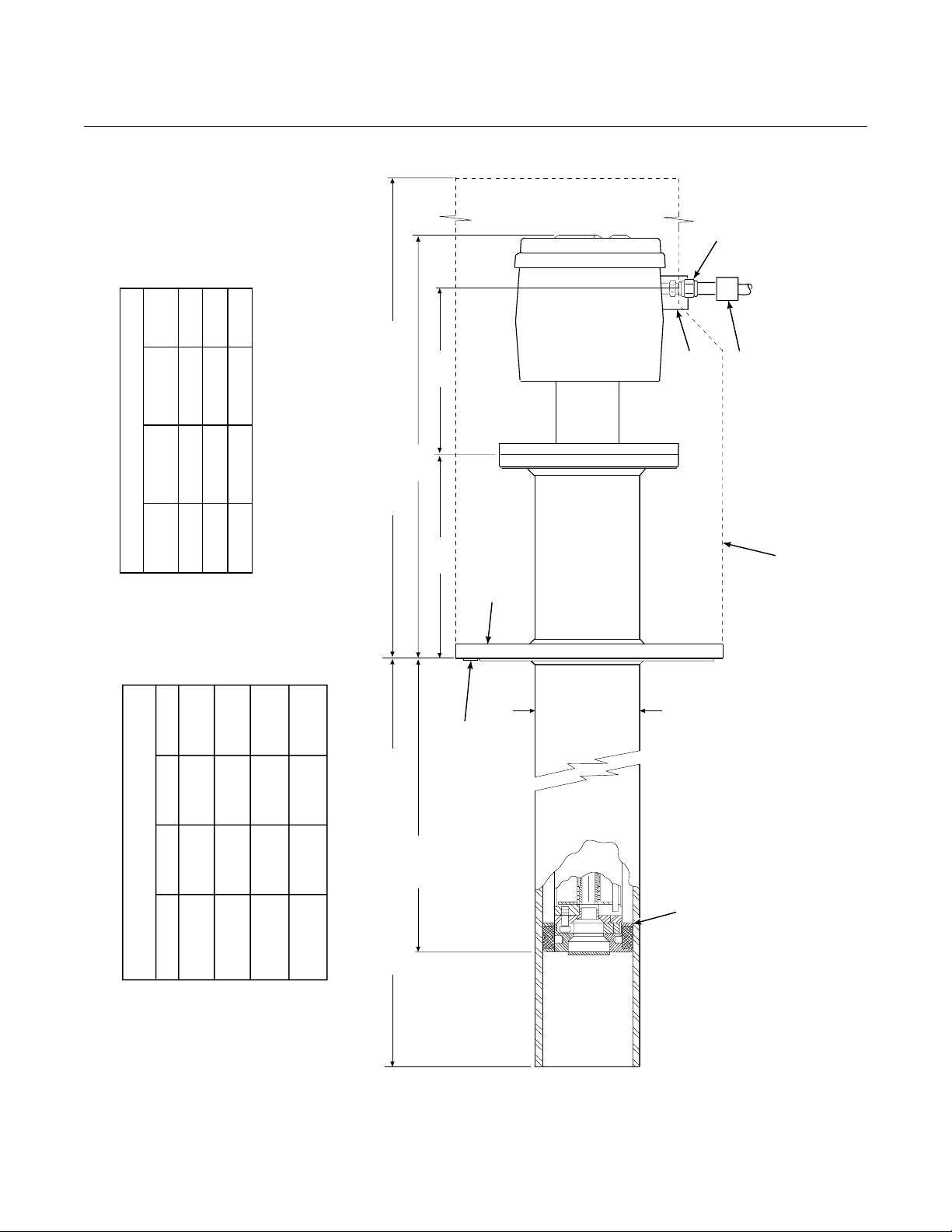
1300°F (10° to 704°C). Figure 2-1 provides mechanical installation
references.
2. Check the flue or stack for holes and
air leakage. The presence of this condition will substantially affect the accuracy of the oxygen reading. Therefore,
either make necessary repairs or install
the probe upstream of any leakage.
3. Ensure that the area is clear of obstructions internal and external that will
interfere with installation. Allow adequate clearance for removal of probe
(Figure 2-1).
Do not allow the temperature of the
probe junction box to exceed 300°°°°F
(149°°°°C) or damage to the unit may re-
sult. If the probe junction box temperature exceeds 300°°°°F (149°°°°C), the user
must fabricate a heat shield or provide
adequate cooling air to the probe junction box.
b. Mechanical Installation
1. Ensure that all components are available for installation of the probe.
Ensure that the system cable is the required length. If applicable, check the
ceramic filter to ensure that it is not
damaged.
2. The probe may be installed intact as it
is received. It is recommended that you
disassemble the adapter plate for each
installation.
NOTE
An abrasive shield is recommended
for high velocity particulate in the flue
stream (such as those in pulverized
coal kilns and recovery boilers). Vertical and horizontal brace clamps are
provided for 9 ft and 12 ft (2.75 m and
3.66 m) probes to provide mechanical
support of the probe. Refer to Figure
2-1, Sheet 5.
3. Weld or bolt adapter plate (Figure 2-1)
onto the duct.
Rosemount Analytical Inc. A Division of Emerson Process Management Installation 2-1
Instruction Bulletin
106-300NE Rev. 3.4
May 2000
World Class 3000
FURNISHED IN - XIT
4512C34
ADAPTER & ACCESSORY
TO AMBIENT
INSULATE IF EXPOSED
WEATHER CONDITIONS
4512C35
4512C36
2.27 (58)
DIA MAX
ROSEMOUNT
5.85 (148.6)
DIM "A"
WITH STANDARD
REF GAS
CAL GAS
7.58 (192)
SNUBBER
DIFFUSER
ELEC
DIM "B" REMOVAL ENVELOPE
1/4 IN. TUBE
6 MM TUBE
6 MM TUBE
ANSI
DIN
JIS
1/2"
CONN
CONDUIT
GAS
CAL
JIS
4512C18H01
6.10
(155)
1.88 (48)
(15)
0.59
GAS
REF
AT THE BOTTOM
BOTTOM VIEW
INSTALL WITH CONNECTIONS
5.12
(130)
THESE FLAT FACED FLANGES ARE MANUFACTURED
TO ANSI, DIN, AND JIS BOLT PATTERNS AND ARE NOT
DIMENSIONS ARE IN INCHES WITH MILLIMETERS IN
PARENTHESES.
PRESSURE RATED.
2.
NOTES: 1.
24610001
3.80 (96.5)
DIFFUSER
FOR PROBE
WITH CERAMIC
4.90 (124.5)
ADD TO DIM "A" FOR
ARRESTOR
DIFFUSER AND FLAME
PROBE WITH CERAMIC
DIN
7.28
4512C19H01
ANSI
6.00
4512C17H01
(185)
(153)
0.71
0.75
(18)
(20)
5.71
(145)
4.75
(121)
DIM "B"
DIM "A"
27.3 (694)
16 (406)
45.3 (1151)
34 (864)
81.3 (2065)
117.3 (2980)
70 (1778)
106 (2692)
153.3 (3894)
142 (3607)
3535B18H02
3635B48H01
ANSI
JIS
0.062 THK GASKET
ADD TO DIM "A"
3535B45H01
DIN
TABLE I MOUNTING FLANGE
3FT
6FT
9FT
12 FT
PROCESS FLOW MUST
BE IN THIS DIRECTION
WITH RESPECT TO
DEFLECTOR 3534848G01
FLANGE
DIA.
HOLE
DIA.
(4) HOLES
EQ SP ON BC
TABLE II INSTALLATION/REMOVAL
18 IN.
PROBE
Figure 2-1. Probe Installation (Sheet 1 of 5)
2-2 Installation Rosemount Analytical Inc. A Division of Emerson Process Management
World Class 3000
2
7.50
7.48
0.75
9.25 (235)
*
JIS
7.48
0.945
9.25 (235)
*
DIN
* FLANGE ARE MANUFACTURED TO ANSI,
TABLE IV. FLANGE SIZE
BOLT
CIRCLE
0.75
(8) HOLES
DIAMETER
FLANGE
9.00 (153)
DIAMETER
*
ANSI
DIN, AND JIS BOLT PATTERNS AND ARE
FLAT FACED. THESE FLANGES ARE NOT
PRESSURE RATED.
5.7
(145)
14.5
(369)
DIM "D" REMOVAL ENVELOPE
7.00
(178)
SEE TABLE IV
FOR FLANGE
SIZES
Instruction Bulletin
106-300NE Rev. 3.4
May 2000
21190008
REF AND
CAL GAS
CONNECTOR
ELECTRICAL
CONNECTOR
CAL GAS LINES
CHECK VALVE FOR
INSULATE IF
CONDITIONS
EXPOSED TO
AMBIENT WEATHER
31.1
(790)
45.3
(1151)
DIM "D" DIM "E"
27
(686)
DIM "C"
NOMINAL MEASUREMENTS
TABLE III. REMOVAL / INSTALLATION
3FT
67.1
81.3
63
6FT
(1704)
(2065)
(1600)
103.1
(2619)
117.3
(2980)
99
(2515)
9FT
139.1
(3533)
153.3
(3894)
(P/N 3535B58G04 - JIS)
135
12 FT
(3429)
DIM "C"
0.06 THK GASKET FURNISHED
DIM "E" (WITH FLAME ARRESTOR)
(P/N 3535B58G06 - DIN)
(P/N 3535B58G02 - ANSI)
IN HARDWARE PACKAGE
Figure 2-1. Probe Installation (Sheet 2 of 5)
3.6
NOMINAL
(P/N 4843B38G02)
SNUBBER DIFFUSION/
DUST SEAL ASSEMBLY
DIMENSIONS ARE IN INCHES WITH
MILLIMETERS IN PARENTHESES.
NOTE:
Rosemount Analytical Inc. A Division of Emerson Process Management Installation 2-3
Instruction Bulletin
106-300NE Rev. 3.4
May 2000
JIS
(P/N 3535B58G04)
9.25
(235)
4.92
(125)
(M-20 x 2.5)
(200)
7.894
World Class 3000
16860021
8 THREADED HOLES
EQUALLY SPACED ON
D DIA B.C.
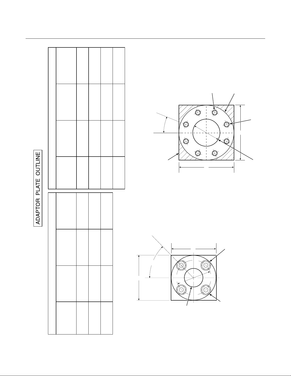
ABRASIVE SHIELD
FLANGE O.D.
TABLE VI. ADAPTOR PLATE DIMENSIONS FOR ABRASIVE SHIELD
DIN
ANSI
IN.
DIMENSIONS
JIS
9.25
(P/N 3535B58G06)
9.00
(P/N 3535B58G02)
"A"
(mm)
6.50
(P/N 4512C35G01)
(235)
(229)
(165)
3.94
(100)
4.75
(121)
"B"
DIA
(M-12 x 1.75)
(M-16 x 2)
0.625-11
"C"
THREAD
(130)
5.118
7.48
7.50
"D"
(190)
(191)
DIA
ATTACHING HARDWARE.
NOTE: PART NUMBERS FOR ADAPTOR PLATES INCLUDE
o
22.5
A
CORNERS MAY BE USED TO
FIELD BOLTING OF PLATE TO
PROVIDE ADDITIONAL HOLES FOR
OUTSIDE WALL SURFACE.
AND 12 FT ABRASIVE SHIELD
ADAPTOR PLATE FOR 3, 6, 9,
INSTALLATIONS. SEE SHEET 2.
CROSSHATCHED AREA IN 4
C
A
B
4 STUDS,
LOCKWASHERS AND
NUTS EQUALLY
SPACED ON
C DIA B.C.
B
ADAPTOR PLATE FOR
STD WORLD CLASS 3000
PROBE INSTALLATION.
SEE SHEET 1.
TABLE V. ADAPTOR PLATE DIMENSIONS FOR PROBE
DIN
ANSI
IN.
DIMENSIONS
7.5
(P/N 4512C36G01)
6.00
(P/N 4512C34G01)
"A"
(mm)
(191)
(153)
(M-16 x 2)
0.625-11
"B"
THREAD
(145)
5.708
4.75
(121)
"C"
DIA
A
o
45
A
C
ATTACHING HARDWARE.
2.500 DIA
NOTE: PART NUMBERS FOR ADAPTOR PLATES INCLUDE
Figure 2-1. Probe Installation (Sheet 3 of 5)
2-4 Installation Rosemount Analytical Inc. A Division of Emerson Process Management
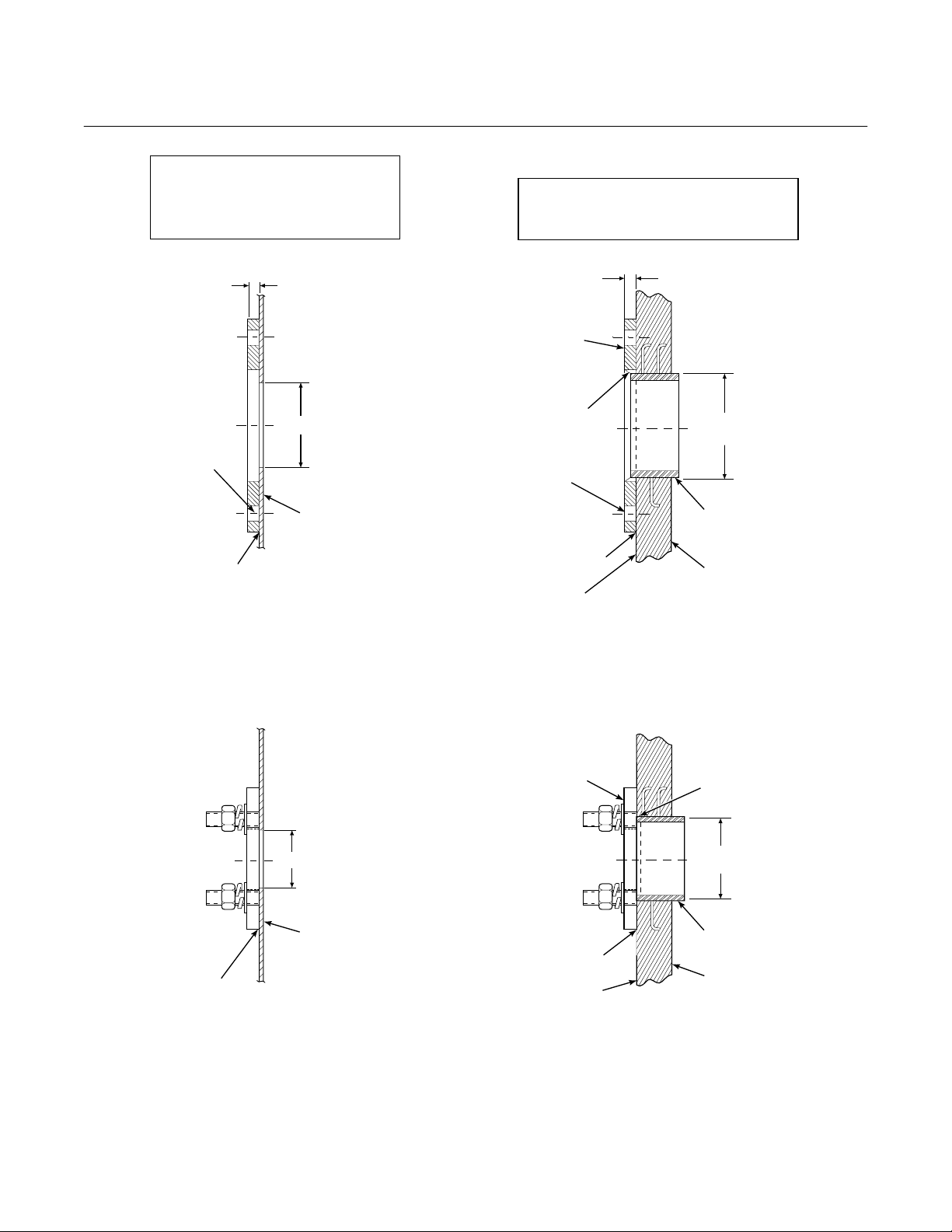
World Class 3000
2
INSTALLATION FOR METAL
WALL STACK OR DUCT
CONSTRUCTION
Instruction Bulletin
106-300NE Rev. 3.4
May 2000
INSTALLATION FOR MASONRY
WALL STACK CONSTRUCTION
MTG HOLES
SHOWN ROTATED
o
22.5 OUT OF
TRUE POSITION
WELD OR BOLT MOUNTING
PLATE TO METAL WALL
OF STACK OR DUCT.
JOINT MUST BE AIRTIGHT.
0.50 (13)
3.75 (95)
MIN DIA HOLE
IN WALL
STACK OR DUCT
METAL WALL
BOLT ADAPTOR
PLATE TO OUTSIDE
WALL SURFACE
FIELD WELD
PIPE TO
ADAPTOR PLATE
MTG HOLES
SHOWN ROTATED
o
22.5 OUT OF
TRUE POSITION
JOINT MUST
BE AIRTIGHT
OUTSIDE WALL
SURFACE
NOTE: ALL MASONRY STACK WORK AND JOINTS EXCEPT
ADAPTOR PLATE NOT FURNISHED BY ROSEMOUNT.
ABRASIVE SHIELD MOUNTING
0.50 (13)
4.50 (114)
O.D. REF
PIPE 4.00 SCHED 40
PIPE SLEEVE (NOT
BY ROSEMOUNT)
LENGTH BY CUSTOMER
MASONRY
STACK WALL
WELD OR BOLT MOUNTING
PLATE TO METAL WALL
OF STACK OR DUCT.
JOINT MUST BE AIRTIGHT.
3.25 (82.5)
MIN DIA HOLE
IN WALL
STACK OR DUCT
METAL WALL
BOLT MOUNTING
PLATE TO OUTSIDE
WALL SURFACE
OUTSIDE WALL
PROBE MOUNTING
JOINT MUST
BE AIRTIGHT
SURFACE
NOTE: DIMENSIONS IN INCHES WITH
MILLIMETERS IN PARENTHESES.
FIELD WELD
PIPE TO
ADAPTOR PLATE
4.0 (102)
O.D. REF
PIPE 3.5 SCHED 40
PIPE SLEEVE (NOT
BY ROSEMOUNT)
LENGTH BY CUSTOMER
MASONRY
STACK WALL
P0038
Figure 2-1. Probe Installation (Sheet 4 of 5)
Rosemount Analytical Inc. A Division of Emerson Process Management Installation 2-5
Instruction Bulletin
106-300NE Rev. 3.4
May 2000
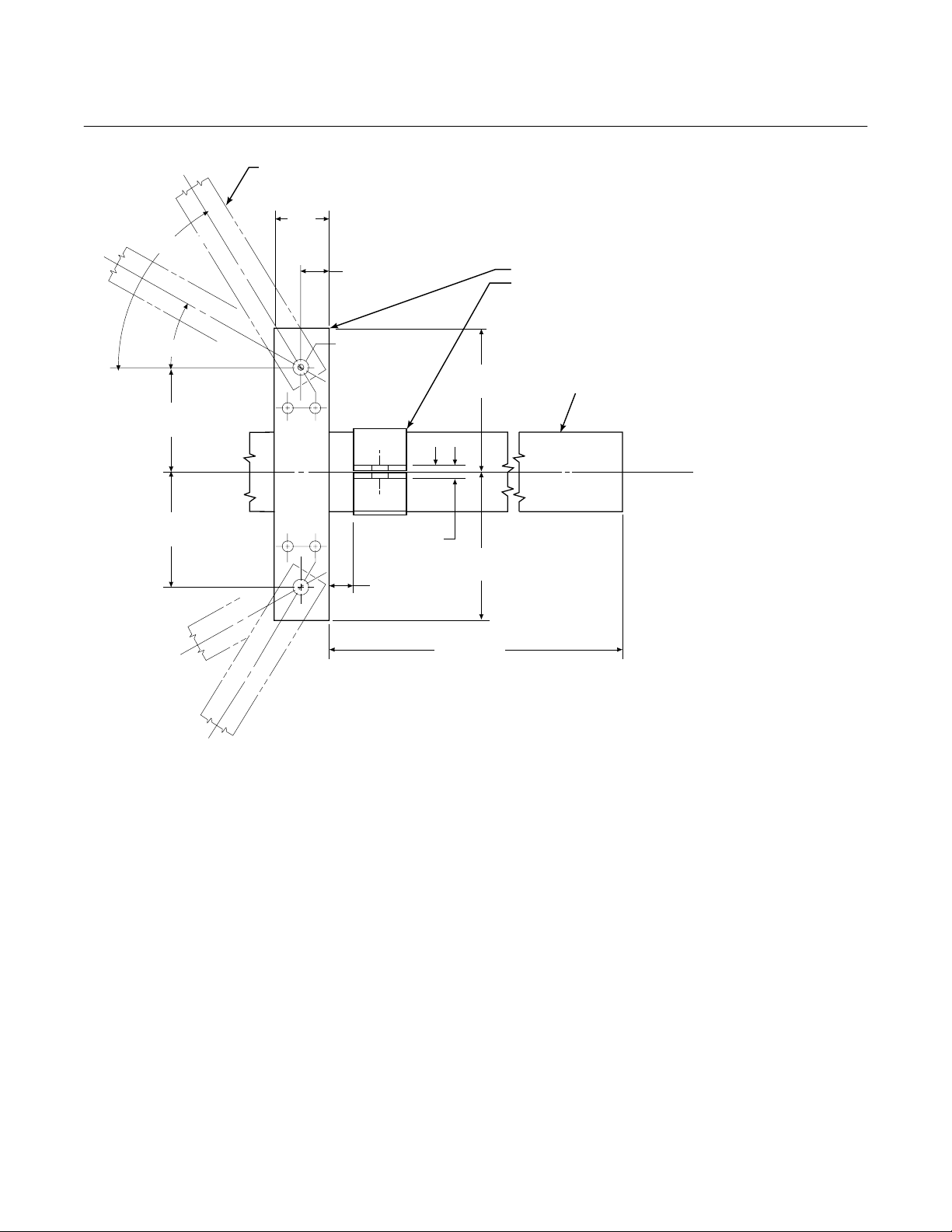
World Class 3000
o
60 MAX.
o
30 MIN.
4.12
(105)
4.12
(105)
BRACE BARS
(NOT BY ROSEMOUNT)
2.00
(51)
1.00
(25)
2 HOLES - 0.625
(16) DIA. FOR
0.50 (12) DIA.
BOLT
1.00
(25) MAX.
0.375
(10)
NOTE: DIMENSIONS IN INCHES WITH
MILLIMETERS IN PARETHESES.
VERTICAL BRACE CLAMP ASSY.
HORIZONTAL BRACE CLAMP ASSY.
(BOTH BRACE CLAMP ASSEMBLIES ARE THE SAME.
INSTALLATION AND LOCATION OF CLAMP ASSEMBLIES
AND BRACE BARS TO BE DONE IN FIELD.)
5.62
(143)
5.62
(143)
ABRASIVE SHIELD
BY ROSEMOUNT
}
NOTE: BRACING IS FOR VERTICAL AND HORIZONTAL PROBE INSTALLATION.
EXTERNAL BRACING REQUIRED FOR 9 FT AND 12 FT
(2.75 M AND 3.66 M) PROBES AS SHOWN ABOVE.
Figure 2-1. Probe Installation (Sheet 5 of 5)
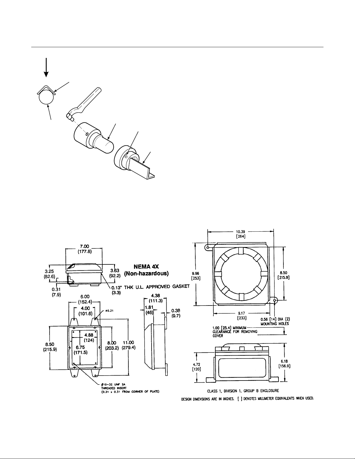
4. If using the optional ceramic diffusor
element, the vee deflector must be correctly oriented. Before inserting the
probe, check the direction of gas flow
in the duct. Orient the vee deflector on
the probe so that the apex points upstream toward the flow (Figure 2-2).
This may be done by loosening the
setscrews, and rotating the vee deflector to the desired position.
Retighten the setscrews.
5. In horizontal installations, the probe
junction box should be oriented so the
system cable drops vertically from the
probe junction box. In a vertical installation, the system cable can be oriented in any direction.
36.00 (914)
P0039
6. If the system has an abrasive shield,
check the diffusion element dust seal
packings. The joints in the two packings must be staggered 180°. Also,
make sure that the packings are in the
hub grooves as the probe slides into
the 15° forcing cone in the abrasive
shield.
7. Insert the probe through the opening in
the mounting flange and bolt the unit to
the flange. When probe lengths selected are 9 or 12 feet (2.74 or 3.66 m),
special brackets are supplied to provide additional support for the probe
inside the flue or stack. See Figure 2-1,
sheet 5.
2-6 Installation Rosemount Analytical Inc. A Division of Emerson Process Management
World Class 3000
2
Instruction Bulletin
106-300NE Rev. 3.4
May 2000
GAS FLOW
DIRECTION
VEE
FILTER
DEFLECTOR
DIFFUSION
ELEMENT
SETSCREW
DEFLECTOR
VEE
P0017
APEX
Figure 2-2. Orienting the Optional Vee Deflector
c. Service Required
1. Power input: 100, 115 or 220 Vac single phase, 50 to 60 Hz, 3 amp
minimum. (See label.)
2. Compressed air: 10 psig (68.95 kPag)
minimum, 225 psig (1551.38 kPag)
maximum at 2 scfh (56.6 L/hr) maximum; supplied by one of the following
(less than 40 parts-per-million total hydrocarbons). Regulator outlet pressure
should be set at 5 psi (35 kPa).
(a) Instrument air - clean, dry.
(b) Bottled standard air with step-down
regulator.
(c) Bottled compressed gas mixture
(20.95% oxygen in nitrogen).
(d) Other equivalent clean, dry, oil-free
air supply.
Figure 2-3. Outline of Heater Power Supply
Rosemount Analytical Inc. A Division of Emerson Process Management Installation 2-7
Instruction Bulletin
106-300NE Rev. 3.4
May 2000
World Class 3000
EXISTING
ELECTRONICS
YE
RD
OR
BL
BK
WH
GN
SHIELD
YE
RD
OR
BL
BK
WH
GN
SHIELD
SHIELD
*TRIAC RELAY
}
+
J9
PROBE
MV
}
+
J8
BL
OR
PROBE
MV
}
+
J3
BL
OR
STACK
TC
}
+
J2
}
+
PROBE
TC
}
+
YE
PROBE
+
SHIELD
PROBE
HEATER
STACK
TEMP
+
AD590
+
RD
TC
}
YE
RD
}
RH
BK
WH
}
}
SHIELD
GN
ANALOG
HEATER
}
BK WH
BK
GN
SHIELD
WH
(SEE PARAGRAPH 2.2.b)
MAINS
J1
LINE VOLTAGE
BY CUSTOMER
}
NL
HEATER POWER SUPPLY
*GATE VOLTAGE CONTROLLING TRIAC OUTPUT
STANDARD PROBE CABLE
6 M (20 FT)
HEATER
}
BL CELL -VE
OR CELL +VE
YE CHROMEL
RD ALUMEL
1234567
BL
2-8 Installation Rosemount Analytical Inc. A Division of Emerson Process Management
YE
RD
OR
PROBE HEAD
WIRING
GN
BK
BK
8
BK
GN
WH
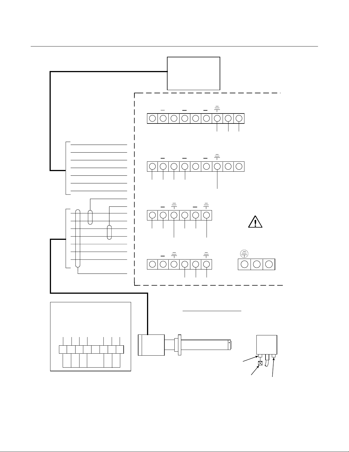
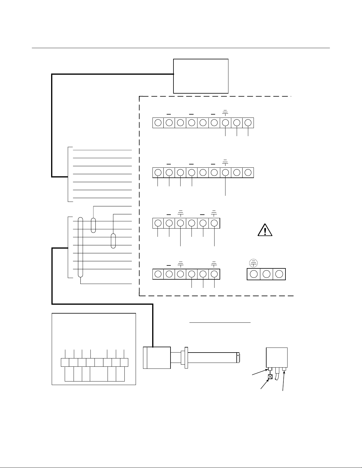
Figure 2-4. Electrical Installation of Heater Power Supply
12 M (40 FT)
18 M (60 FT)
PROBE
24 M (80 FT)
30 M (100 FT)
45 M (150 FT)
TEST GAS INPUT
AT 2-3 L/MIN
(4-7 SCFH)
CHECK
VALV E
REF. GAS SUPPLY
INPUT AIR AT
1 L/MIN (2 SCFH)
19260003
World Class 3000
2
Instruction Bulletin
106-300NE Rev. 3.4
May 2000
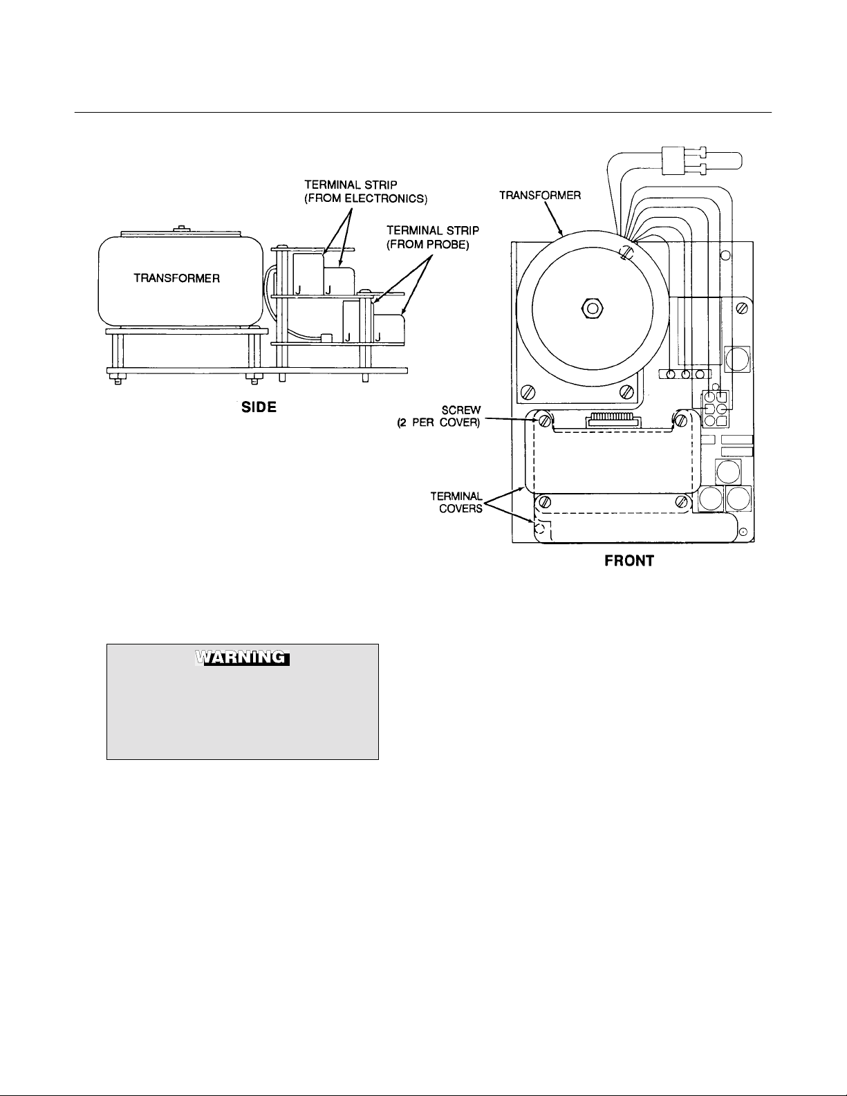
Figure 2-5. Heater Power Supply Wiring Connections
2-2 HEATER POWER SUPPLY INSTALLATION
Install all protective equipment covers
and safety ground leads after installation. Failure to install covers and
ground leads could result in serious
injury or death.
a. Mechanical Installation
The outline drawing of the heater power
supply enclosure, Figure 2-3, shows
mounting centers and clearances. The
NEMA 4X enclosure is designed to be
mounted on a wall or bulkhead. The heater
power supply should be installed no further
than 150 feet (45 m) from the probe. The
heater power supply must be located in a
location free from significant ambient tem-
perature changes and electrical noise.
Ambient temperature must be between -20°
to 140°F (-30° to 60°C).
b. Electrical Connections
1. Electrical connections should be made
as described in the electrical installation diagram, Figure 2-4. The wiring
terminals are divided into two layers;
the bottom (FROM PROBE) terminals
should be connected first, the top
(FROM ELECTRONICS) terminals
should be connected (Figure 2-5).
Each terminal strip has a protective
cover which must be removed when
making connections. To remove the
terminal covers, remove two slotted
screws holding the cover in place. Always reinstall terminal covers after
making connections.
Rosemount Analytical Inc. A Division of Emerson Process Management Installation 2-9
Instruction Bulletin
106-300NE Rev. 3.4
May 2000
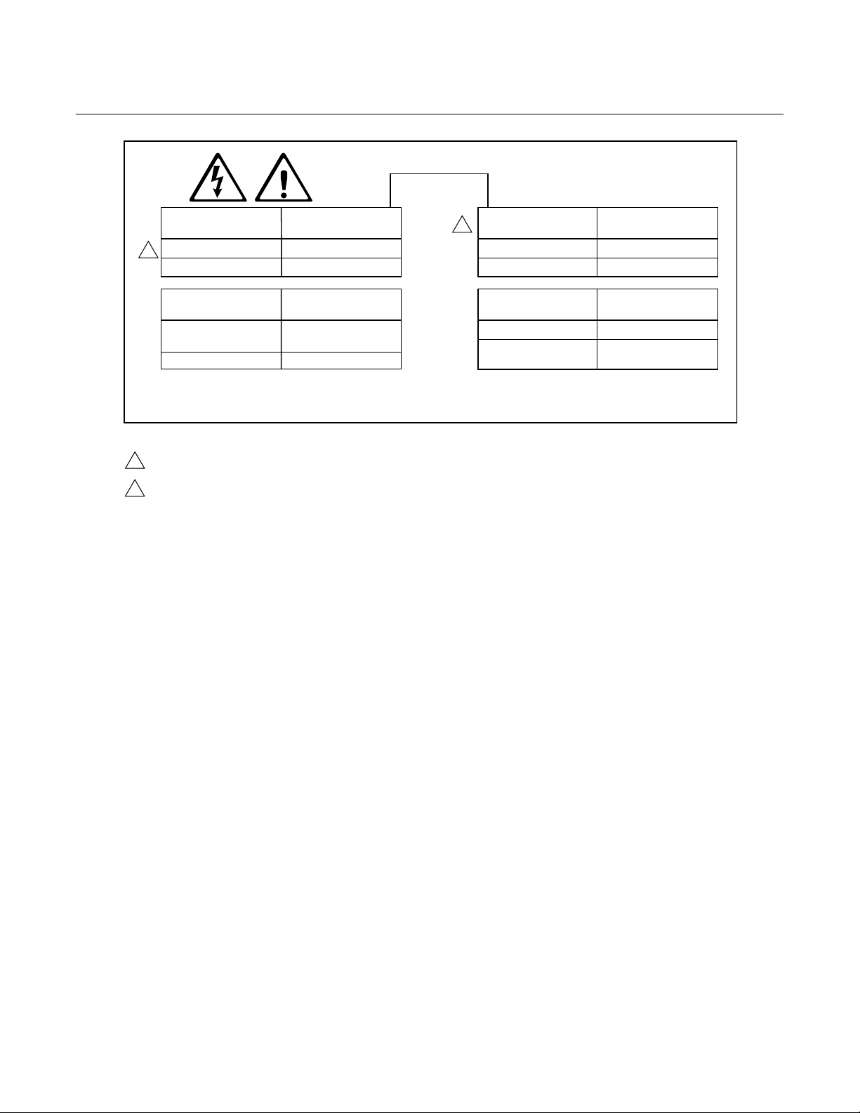
LINE VOLTAGE
SELECTION
1
100/120 V.A.C.
220/240 V.A.C.
JUMPER
(INSTALL)
JM4, JM1
JM5
JUMPER
CONFIGURATIONS
2
World Class 3000
ALWAYS DISCONNECT LINE VOLTAGE
FROM HEATER POWER SUPPLY AND
ANALOG ELECTRONICS (IF USED)
BEFORE CHANGING JUMPERS.
HEATER
POWER
REMOTE
*ON
JUMPER
REMOVE JM2
INSTALL JM2
PROBE HEATER
VOLTAGE SELECTION
*WORLD CLASS PROBE
(44V)
218 PROBE (115V)
DENOTES JUMPERS THAT MUST BE INSTALLED WHEN USING THE WORLD CLASS 3000 OXYGEN ANALYZER
*
PROBE AND THE HPS 3000 HEATER POWER SUPPLY WITH EXISTING ANALOG, MODEL 218A, AND TC 2000
ELECTRONICS.
NOTES:
1
100 V.A.C. OPERATION REQUIRES TRANSFORMER PART NUMBER 1M02961G02.
2
HEATER POWER IS ALSO REFERRED TO AS LINE VOLTAGE RELAY.
JUMPER
(INSTALL)
JM7
JM8
ELECTRONICS
SELECTION
*ANALOG (EXISTING)
(NEXT GENERATION)
Figure 2-6. Jumper Selection Label
NOTE
Refer to Figure 2-7 for HPS unit fuse
locations and specifications.
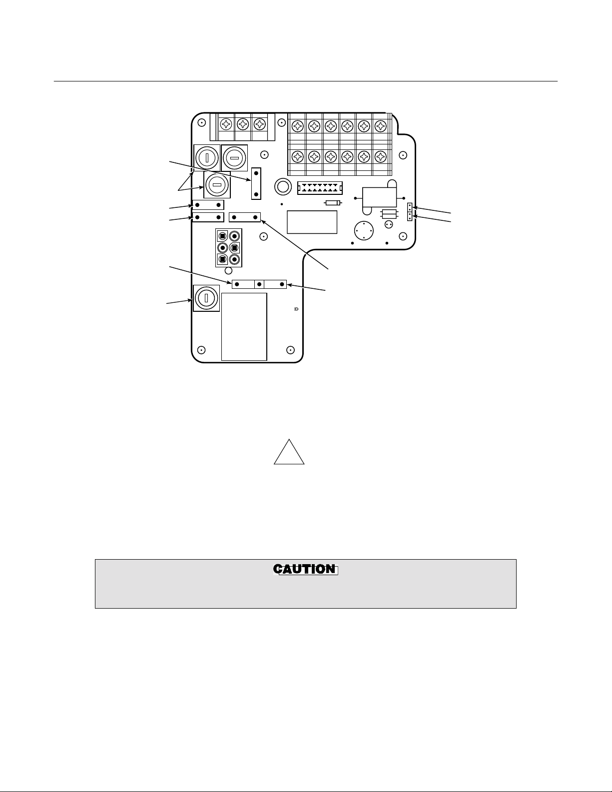
NOTE
Before supplying power to the heater
power supply, verify that jumpers JM2,
JM3, JM6, and JM7 are installed.
2. Power Input: 120, 220 or 240 Vac. For
"ANALOG" under ELECTRONICS SELECTION on the label refers to Models
218, 225, TC200, and Model 218A electronics.
120 Vac usage, install jumpers JM4
and JM1. For 220 or 240 Vac usage,
install jumper JM5 (See label, Figure
2-6).
For 100 Vac usage, the heater power
supply is factory-supplied with a different transformer. When using the HPS
with 100 Vac transformer, install
jumpers JM1 and JM4.
JUMPER
INSTALL JM3, JM6
DIGITAL
REMOVE JM3, JM6
3. The power cable should comply with all
applicable codes and safety regulations in the user's country and should
not be smaller than 16 gauge, 3 amp.
NOTE
4. Before supplying power to the heater
power supply, verify that the jumpers
on the mother board, Figure 2-7, are
properly configured. Jumpers JM2,
JM3, JM6, and JM7 should be installed. Additionally, make sure that the
proper jumper for your line voltage is
installed, Figure 2-6.
2-10 Installation Rosemount Analytical Inc. A Division of Emerson Process Management
World Class 3000
2
JM1
FUSES
JM2
JM4
JM7
FUSE
3D3 080G REV
JM5
JM8
NOTE:
Instruction Bulletin
106-300NE Rev. 3.4
May 2000
JM3
JM6
ALL FUSES ARE 5A @ 250 VAC,
ANTI-SURGE, CASE SIZE
5 X 20 MM, TYPE T TO IEC127,
SCHURTER.
22540005
Figure 2-7. Jumpers on HPS Mother Board
NOTE
!
Upon completing installation, make sure that the probe is turned on and operating
prior to firing up the combustion process. Damage can result from having a cold
probe exposed to the process gases.
During outages, and if possible, leave all probes running to prevent condensation and
premature aging from thermal cycling.
If the ducts will be washed down during outage, MAKE SURE to power down the
probes and remove them from the wash area.
Rosemount Analytical Inc. A Division of Emerson Process Management Installation 2-11
 Loading...