

Emerson Wireless Field Link
Quick Start Guide
00825 0100-4421, Rev DC
September 2020

Quick Start Guide September 2020
NOTICE
This guide provides basic guidelines for the Emerson Wireless Field Link. It does not provide
instructions for diagnostics, maintenance, service, or troubleshooting. This guide is also available
electronically on www.Emerson.com.
WARNING
Failure to follow these installation guidelines could result in death or serious injury.
Ensure only qualified personnel perform the installation.
Explosions could result in death or serious injury.
Installation of the transmitters in a hazardous environment must be in accordance with the
appropriate local, national, and international standards, codes, and practices. Please review the
Product Certifications section for any restrictions associated with a safe installation.
Electrical shock could cause death or serious injury.
Avoid contact with the leads and terminals. High voltage that may be present on leads can cause
electrical shock.
This device complies with Part 15 of the FCC Rules. Operation is subject to the following
conditions:
This device may not cause harmful interference.
This device must accept any interference received, including interference that may cause undesired
operation.
This device must be installed to ensure a minimum antenna separation distance of 8-in. (20 cm) from
all persons.
Contents
Wireless considerations................................................................................................................3
Physical installation...................................................................................................................... 6
Verify operation........................................................................................................................... 8
Reference information................................................................................................................. 9
Ordering information................................................................................................................. 11
Product certifications................................................................................................................. 13
2 Emerson.com/Rosemount

A
B
C
D
E
15- to 25-ft.
(4,6 to 7,6 m)
6-ft. (2 m)
September 2020 Quick Start Guide
1 Wireless considerations
1.1 Power up sequence
The Emerson Wireless Field Link and wireless I/O should be installed and
functioning properly before the power modules are installed in any wireless
field devices. Wireless field devices should also be powered up in order of
proximity from the Field Link beginning with the closest. This will result in a
simpler and faster network installation.
1.2 Mounting location
The Field Link should be mounted in a location that allows convenient access
to the host system network (wireless I/O) as well as the wireless field device
network.
Find a location where the Field Link has optimal wireless performance.
Ideally this will be 15 to 25 ft. (4,6 to 7,6 m) above the ground or 6 ft. (2 m)
above obstructions or major infrastructure.
Figure 1-1: Mounting Location
A
Control room
B
Ground
C
Field link
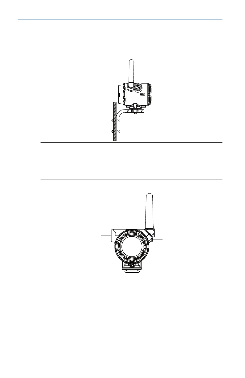
1.3 Antenna position
The antenna should be positioned vertically, either straight up or straight
down, and should be approximately 3 ft. (1 m) from any large structure,
Quick Start Guide 3
D
E
Mast or pipe
Infrastructure
A
A
Quick Start Guide September 2020
building, or conductive surface to allow for clear communication to other
devices.
Figure 1-2: Antenna Position
1.4 Conduit plug
The temporary orange plugs should be replaced with the included conduit
plugs using approved thread sealant.
Figure 1-3: Conduit Plugs
A
Conduit plug
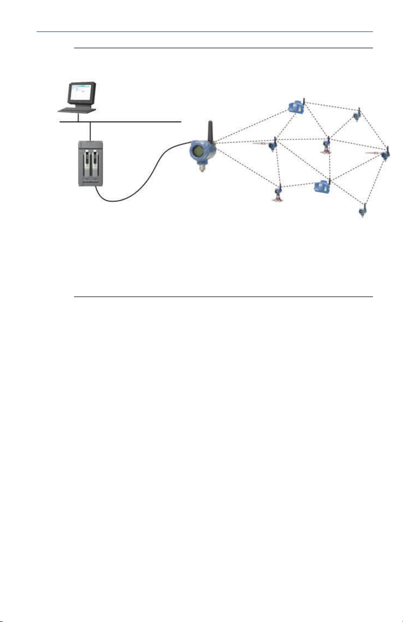
1.5 Intended use
The Field Link must be used in conjunction with a network manager or
network Gateway. The Field Link then functions as a translator between the
wired network and a wireless field network.
4 Emerson.com/Rosemount
A
B
C
D
E
F
September 2020 Quick Start Guide
Figure 1-4: Example System Architecture
A
Host system
B
Control network
C
Network manager
D
Field link
E
Wireless field network
F
Wireless field devices
Quick Start Guide 5
Quick Start Guide September 2020
2 Physical installation
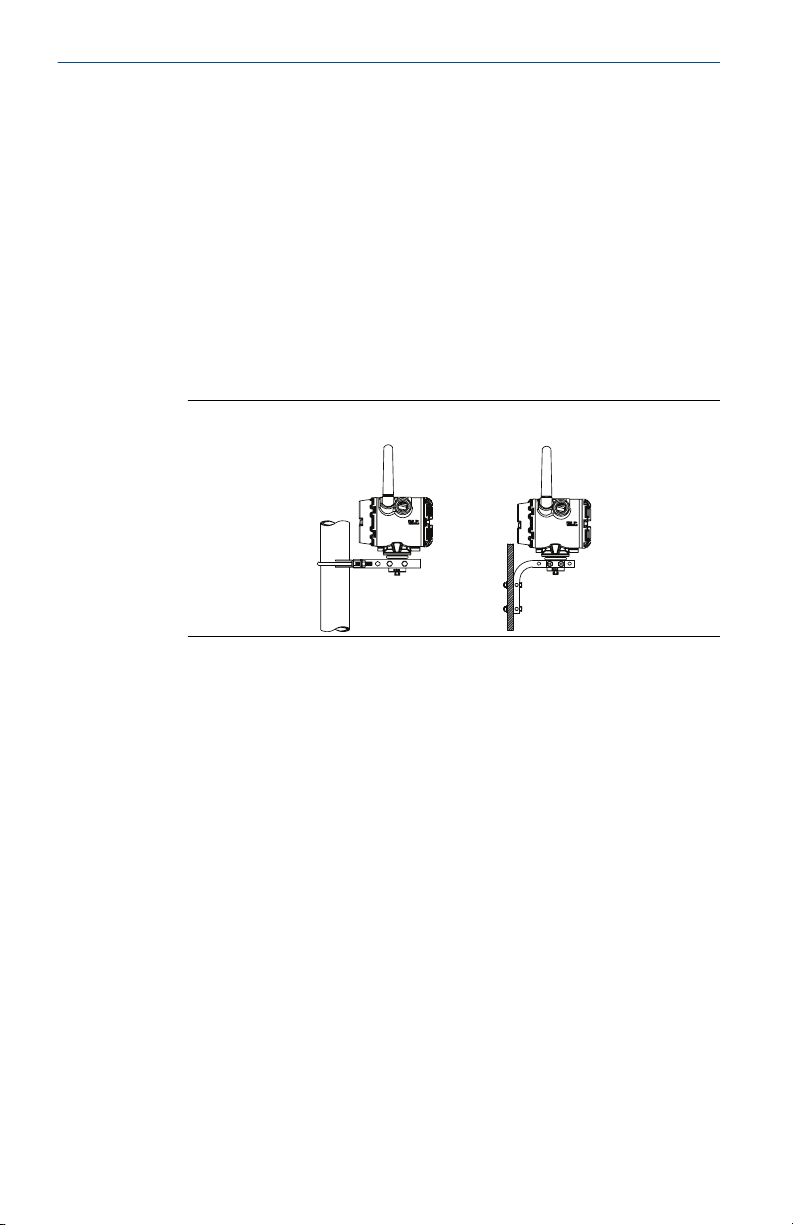
2.1 Pipe mounting
Procedure
1. Insert larger U-bolt around 2-in. pipe/mast, through the saddle,
through the L-shaped bracket, and through the washer plate.
2. Use a 1/2-in. socket-head wrench to fasten the nuts to the U-bolt.
3. Insert smaller U-bolt around base the Field Link and through the Lshaped bracket.
4. Use a 1/2-in. socket-head wrench to fasten the nuts to the U-bolt.
Figure 2-1: Mounting
2.2 Power and data wiring
Procedure
1. Remove housing cover labeled “Field Terminals.”
2. Connect the positive power lead to the “+” power terminal and the
negative power lead to the “–” terminal.
3. Connect the Data + lead to the “A (+)” terminal and the Data – lead
to the “B (–)” terminal.
4. Plug and seal any unused conduit connections.
5. Replace the housing cover.
6 Emerson.com/Rosemount

A
B
C
D
September 2020 Quick Start Guide
Figure 2-2: Emerson Wireless Field Link Terminal Diagram
A Data A (+)
B Data B (–)
C +10.5 to 30 VDC
D Return
2.3 Grounding
The Field Link enclosure should always be grounded in accordance with
national and local electrical codes. The most effective grounding method is a
direct connection to earth ground with minimal impedance. Ground the
Field Link by connecting the external ground lug to earth ground. The
connection should be 1 Ω or less.
Quick Start Guide 7

Quick Start Guide September 2020
3 Verify operation
3.1 Power-up sequence
Upon applying power to the Field link the LCD display meter will activate and
display a series of startup screen. The following screens are displayed during
startup.
1. Startup Screen 1 – All segments on
2. Startup Screen 2 – Device identification
3. Startup Screen 3 – Tag
4. Startup Screen 4 – Status
3.2 Normal operation
After the initial startup screens the Field Link will cycle through several
periodic screens.
1. Electronics Temperature Screen
2. Percent Range Screen
3. Wired Interface Usage
4. Radio Interface Usage
The Field Link will continue to rotate through each periodic screen through
the course of normal operation. If any diagnostic or fault condition occurs, a
corresponding diagnostics screen will appear.
8 Emerson.com/Rosemount

A
B
C
D
September 2020 Quick Start Guide
4 Reference information
Figure 4-1: Emerson Wireless Field Link Terminal Diagram
A
B
C
D
Data A (+)
Data B (–)
+10.5 to 30 VDC
Return
Note
The Emerson Wireless Field Link requires separate twisted shield pairs (four
wires) for power and data.
Quick Start Guide 9

A
B
C
D
90°
5.51
(140)
4.20
(107)
3.55
(90.17)
10.91
(277)
12.43
(316)
3.55
(90.17)
5.51
(140)
5.21
(132)
Quick Start Guide September 2020
Figure 4-2: Emerson Wireless Field Link Dimensional Drawing
A
2x Conduit plug
B
Possible antenna rotation shown
C
Extended range antenna
D
WirelessHART® antenna
Table 4-1: Emerson Wireless Field Link Specifications
Item Specifications
Input power 10.5 – 30 VDC
Operating temperature –40 to 185 °F (–40 to 85 °C)
Wiring (power) 24 AWG - 14 AWG twisted shielded pair
Wiring (RS-485
communications)
Wiring distance 656 ft. (200 m)
Wireless protocol WirelessHART, 2.4 – 2.5 GHz DSSS
Wireless output power,
EIRP
Mounting All SST, 2-in. pipe and panel mount bracket
Humidity 0 – 90% relative humidity
(1) Ambient temperatures above 60 °C require wiring rated to at least 5 °C above
10 Emerson.com/Rosemount
max ambient temperature.
24 AWG - 14 AWG twisted shielded pair
Less than 15 pF/ft capacitance.
10 dBm with WK antenna and 12.5 dBm with WM
antenna
(1)
(1)

September 2020 Quick Start Guide
5 Ordering information
Table 5-1: Emerson Wireless Field Link
The Standard offering represents the most common options. The starred options (★)
should be selected for best delivery. The expanded offering is subject to additional
delivery lead time.
Model Product description
781 Emerson Wireless Field Link
Physical connection
A1 RS485 ★
Housing
D Dual compartment housing - aluminum ★
E Dual compartment housing - stainless steel ★
Conduit threads
1 1/2 – 14 NPT ★
2 M20 ★
Product certifications
I5 USA Intrinsically Safe, Non-incendive ★
I6 Canada Intrinsically Safe ★
I1 ATEX Intrinsic Safety ★
I7 IECEx Intrinsic Safety ★
KD USA and Canada Intrinsically Safe, ATEX and IECEx Intrinsic Safety ★
I2 INMETRO, Intrinsic Safety ★
I4 Japan Intrinsic Safety ★
IM EAC Intrinsic Safety ★
I3 China (NEPSI) Intrinsic Safety ★
KL USA and Canada Intrinsic Safety, ATEX Intrinsic Safety ★
NA No Approvals ★
Wireless update rate, operating frequency and protocol
WA3 WirelessHART ★
Omnidirectional wireless antenna and SmartPower
WK3 External antenna, line power 10 – 30 VDC ★
WM3 Extended range, external antenna, line power 10 – 30 VDC ★
™
Quick Start Guide 11

Quick Start Guide September 2020
Table 5-1: Emerson Wireless Field Link (continued)
Options (Include with selected model number)
Meter
M5 LCD display ★
Gland and connector options
G2 Cable gland (7,5 – 11,9 mm)
G4 Thin wire cable gland (3 – 8 mm)
Typical model number: 781 A1 D 1 KL WA3 WK3 M5
12 Emerson.com/Rosemount

September 2020 Quick Start Guide
6 Product certifications
Rev 1.2
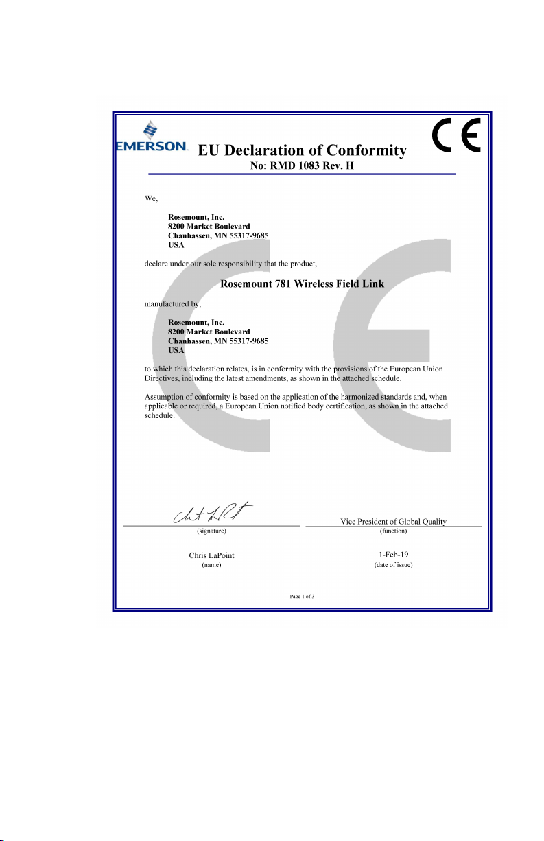
6.1 European Directive Information
A copy of the EU Declaration of Conformity can be found at the end of the
Quick Start Guide. The most recent revision of the EU Declaration of
Conformity can be found at Emerson.com.
6.2 Ordinary Location Certification
As standard, the transmitter has been examined and tested to determine
that the design meets the basic electrical, mechanical, and fire protection
requirements by a nationally recognized test laboratory (NRTL) as accredited
by the Federal Occupational Safety and Health Administration (OSHA).
6.3 Installing in North America
The US National Electrical Code® (NEC) and the Canadian Electrical Code
(CEC) permit the use of Division marked equipment in Zones and Zone
marked equipment in Divisions. The markings must be suitable for the area
classification, gas, and temperature class. This information is clearly defined
in the respective codes.
6.4 USA
I5 USA Intrinsically Safe (IS), Nonincendive (NI) and Dust-ignitionproof
Certificate
Standards
Markings
Input parameters
(power terminals)
V
MAX/Ui
I
MAX/Ii
P
MAX/Pi
Ci = 10 nF Ci = 5 nF Ca/Co = 13.49nF
Quick Start Guide 13
FM 17US0235X
FM Class 3600:2011, FM Class 3610:2010, FM Class
3611:2004, FM Class 3810:2005, ANSI/ISA 60079 – 0:2009,
ANSI/UL 60079 – 11:2009, ANSI/ISA 61010 – 1:2004, ANSI/
NEMA 250:2003, ANSI/IEC 60529:2004;
IS CL I, DIV 1, GP A, B, C, D; CL II, DIV 1, GP E, F, G; Class III T4;
Class 1, Zone 0 AEx ia IIC T4; NI CL I, DIV 2, GP A, B, C, D T4; DIP
CL II, DIV 1, GP E, F, G; CL III T4; when installed per drawing
00781-1010 T4(–40 °C ≤ Ta ≤ +70 °C)
= 30 V V
= 200 mA I
= 1 W P
Input parameters
(sensor terminals)
= 11 V Voc/Uo = 7.14 V
MAX/Ui
= 300 mA Isc/Io = 112 mA
MAX/Ii
= 1 W P
MAX/Pi
Output parameters
(sensor terminals)
= 640 mW
MAX/Po

Quick Start Guide September 2020
Input parameters
(power terminals)
Li = 3.3 μH Li = 2.2 μH La/Lo= 2 mH
Special Conditions for Safe Use (X)
1. The Rosemount 781 transmitter housing contains aluminum and is
considered a potential risk of ignition by impact or friction. Care must
be taken into account during installation and use to prevent impact
and friction.
2. The surface resistivity of the unit is greater than 1 gigaohm. To avoid
electrostatic charge buildup, it must not be rubbed or cleaned with
solvents or a dry cloth.
3. The Rosemount 781 transmitter will not pass the 500 Vrms electric
strength test and this must be taken into account during installation.
6.5 Canada
I6 Canada Intrinsically Safe
Certificate
Standards
Markings
Input parameters
(sensor terminals)
Output parameters
(sensor terminals)
CSA 2330424
CSA C22.2 No. 0-M91, CSA C22.2 No.94-M91, CSA Std. C22.2
No. 142-M1987, CSA-C22.2 No. 157-92, CSA Std. C22.2 No.
60529 – 2005
Intrinsically Safe Class I, Division 1, Groups A, B, C, and D T3C
(Ta ≤ +60 °C) Type 4X; IP 66/67; when installed per
00781-1011
6.6 Europe
I1 ATEX Intrinsic Safety
Certificate
Standards
Markings
Input parameters
(power terminals)
Ui = 30 V Ui = 11 V Uo = 7.14 V
Ii = 200 mA Ii = 300 mA Io = 112 mA
Pi = 1 W Pi = 1 W Po = 1 W
Ci = 0 μF Ci = 5.1 nF Co = 13.9 μF
14 Emerson.com/Rosemount
Baseefa11ATEX0059X
EN IEC 60079-0:2018, EN 60079-11: 2012
II 1 G Ex ia IIC T4 Ga, T4(–40 °C ≤ Ta ≤ +70 °C)
Input parameters
(RS485)
Output parameters
(RS485)

September 2020 Quick Start Guide
Input parameters
(power terminals)
Li = 0 mH Li = 0 mH Lo=1000 μH
Special Conditions for Safe Use (X)
1. The plastic antenna may present a potential electrostatic ignition
hazard and must not be rubbed or cleaned with a dry cloth.
2. The Rosemount 781 enclosure is made of aluminum alloy and given a
protective paint finish; however, care should be taken to protect it
from impact or abrasion if located in a zone 0 environment.
3. The apparatus is not capable of withstanding the 500 V isolation test
required by EN 60079-11. This must be taken into account when
installing the apparatus.
6.7 International
I7 IECEx Intrinsic Safety
Certificate
Standards
Markings
Input parameters
(power terminals)
Ui = 30 V Ui = 11 V Uo = 7.14 V
Ii = 200 mA Ii = 300 mA Io = 112 mA
Pi = 1 W Pi = 1 W Po = 1 W
Ci = 0 μF Ci = 5.1 nF Co = 13.9 μF
Li = 0 mH Li = 0 mH Lo=1000 μH
Input parameters
(RS485)
Output parameters
(RS485)
IECEx BAS 11.0028X
IEC 60079-0: 2011, IEC 60079-11: 2011
Ex ia IIC T4 Ga, T4(–40 °C ≤ Ta ≤ +70 °C)
Input parameters
(RS485)
Output parameters
(RS485)
Special Conditions for Safe Use (X)
1. The plastic antenna may present a potential electrostatic ignition
hazard and must not be rubbed or cleaned with a dry cloth.
2. The Rosemount 781 enclosure is made of aluminum alloy and given a
protective paint finish; however, care should be taken to protect it
from impact or abrasion if located in a zone 0 environment
3. The apparatus is not capable of withstanding the 500 V isolation test
required by EN 60079-11. This must be taken into account when
installing the apparatus.
Quick Start Guide 15

Quick Start Guide September 2020
6.8 EAC – Belarus, Kazakhstan, Russia
IM (EAC) Intrinsic Safety
Certificate
Markings
Input parameters
(power terminals)
Ui = 30 B Ui = 11 B Uo = 7.14 B
Ii = 200 mA Ii = 300 mA Io = 112 mA
Pi = 1 Bt Pi = 1 Bt Po = 1 Bt
Ci = 0 мкΦ Ci = 5.1 HΦ Co = 13.9 мкΦ
Li = 0 MГH Li = 0 MГH Lo=0 MГH
Special Conditions for Safe Use (X)
1. See certificate for special conditions.
6.9 Japan
I4 CML Intrinsic Safety
Certificate
Markings
Special Conditions for Safe Use (X)
1. See certificate for special conditions.
RU C-US.Gb05.B.00643
0Ex ia IIC T4 Ga X
Input parameters
(RS485)
CML 18JPN2024X
Ex ia IIC T4 Ga, –40 ~ + 70 °C
Output parameters
(RS485)
6.10
6.11
16 Emerson.com/Rosemount
Brazil
I2 INMETRO Intrinsic Safety
Certificate
Standards
Markings
Special Conditions for Safe Use (X)
1. See certificate for special conditions.
UL-BR 16.0478X
ABNT NBR IEC 60079-0:2013 ABNT NBR IEC 60079-11:2013
Ex ia IIC T4 Ga, –40 ~ + 70 °C IP66, UL BR
China
I3 NEPSI 本质安全

September 2020 Quick Start Guide
证书
所用标准
标志
GYJ20.1394X(CCC 认证)
GB3836.1 – 2010, GB3836.4 – 2010, GB3836.20-2010
Ex ia IIC T4 Ga
特殊使用条件(X)
1. 产品外壳含有轻金属,用于 0 区时需注意防止由于冲击或摩擦产生
的点燃危险。
2. 天线材质含非金属,使用时须防止产生静电火花,只能用湿布清
理。
3. 此设备不能承受 GB3836.4-2010 标准中第 6.3.12 条规定的 500V 交
流有效值试验电压的介电强度试验。
使用注意事项
1. 产品使用环境温度范围为:-40℃~+70℃
2. 本安电气参数:
输入 最高输入
电压 Ui (V)
Power 30 200 1 0 0
RS485 11 300 1 5.1 0
输出 最高输出
电压 Uo
(V)
RS485 7.14 112 1 13.9 0
最大输入
电流 Ii
(mA)
最大输出
电流 Io
(mA)
最大输入
功率 Pi
(W)
最大输出
功率 Po
(W)
最大内部等效参数
Ci(nF) Li(µH)
最大外部等效参数
Co(µF) Lo(µH)
3. 该产品必须与已通过防爆认证的关联设备配套共同组成本安防爆系
统方可使用于爆炸性气体环境。其系统接线必须同时遵守本产品和
所配关联设备的使用说明书要求,接线端子不得接错。
4. 用户不得自行更换该产品的零部件,应会同产品制造商共同解决运
行中出现的故障,以杜绝损坏现象的发生。
5. 产品的安装、使用和维护应同时遵守产品使用说明书、
GB3836.13-2013“爆炸性环境 第 13 部分:设备的修理、检修、修
复和改造”、GB/T3836.15-2017“爆炸性环境 第 15 部分:电气装置
的设计、选型和安装”、GB/T3836.16-2017“爆炸性环境 第 16 部
分:电气装置的检查与维护”、GB/T 3836.18-2017“爆炸性环境 第
18 部分:本质安全电气系统”、GB50257-2014“电气装置安装工程
爆炸和火灾危险环境电力装置施工及验收规范”的有关规定。
Quick Start Guide 17

Quick Start Guide September 2020
6.12 Combinations
KD
KL
Combination of I1, I5, and I6
Combination of I1, I5, I6, and I7
18 Emerson.com/Rosemount
September 2020 Quick Start Guide
Figure 6-1: Rosemount 781 Declaration of Conformity
Quick Start Guide 19

Quick Start Guide September 2020
20 Emerson.com/Rosemount

September 2020 Quick Start Guide
Quick Start Guide 21

ᴹ
China RoHS
㇑᧗⢙䍘䎵䗷ᴰབྷ⎃ᓖ䲀٬Ⲵ䜘Ԧරࡇ㺘
List of
Rosemount 781
Rosemount 781 Parts with China RoHS Concentration above MCVs
䜘Ԧ〠
Part Name
ᴹᇣ⢙䍘/ Hazardous Substances
䫵
Lead
(Pb)
⊎
Mercury
(Hg)
䭹
Cadmium
(Cd)
ޝԧ䬜
Hexavalent
Chromium
(Cr +6)
ཊⓤ㚄㤟
Polybrominated
biphenyls
(PBB)
ཊⓤ㚄㤟䟊
Polybrominated
diphenyl ethers
(PBDE)
⭥ᆀ㓴Ԧ
Electronics
Assembly
X O O O O
O
༣փ㓴Ԧ
Housing
Assembly
X O O X O
O
ᵜ㺘Ṭ㌫ᦞ
SJ/T11364
Ⲵ㿴ᇊ㘼ࡦ
This table is proposed in accordance with the provision of SJ/T11364.
O:
Ѫ䈕䜘ԦⲴᡰᴹ൷䍘ᶀᯉѝ䈕ᴹᇣ⢙䍘Ⲵ䟿൷վҾ
GB/T 26572
ᡰ㿴ᇊⲴ䲀䟿㾱≲
O: Indicate that said hazardous substance in all of the homogeneous materials for this part is below the limit requirement of
GB/T 26572.
X:
Ѫ൘䈕䜘Ԧᡰ֯⭘Ⲵᡰᴹ൷䍘ᶀᯉ䟼ˈ㠣ቁᴹа㊫൷䍘ᶀᯉѝ䈕ᴹᇣ⢙䍘Ⲵ䟿儈Ҿ
GB/T 26572
ᡰ㿴ᇊⲴ䲀䟿㾱≲
X: Indicate that said hazardous substance contained in at least one of the homogeneous materials used for this part is above
the limit requirement of GB/T 26572.
Quick Start Guide September 2020
22 Emerson.com/Rosemount

September 2020 Quick Start Guide
Quick Start Guide 23
*00825 0100-4421*
00825 0100-4421, Rev. DC
Quick Start Guide
September 2020
Emerson Automation Solutions
6021 Innovation Blvd.
Shakopee, MN 55379, USA
+1 800 999 9307 or +1 952 906 8888
+1 952 949 7001
RFQ.RMD-RCC@Emerson.com
Latin America Regional Office
Emerson Automation Solutions
1300 Concord Terrace, Suite 400
Sunrise, FL 33323, USA
+1 954 846 5030
+1 954 846 5121
RFQ.RMD-RCC@Emerson.com
Asia Pacific Regional Office
Emerson Automation Solutions
1 Pandan Crescent
Singapore 128461
+65 6777 8211
+65 6777 0947
Enquiries@AP.Emerson.com
North America Regional Office
Emerson Automation Solutions
8200 Market Blvd.
Chanhassen, MN 55317, USA
+1 800 999 9307 or +1 952 906 8888
+1 952 949 7001
RMT-NA.RCCRFQ@Emerson.com
Europe Regional Office
Emerson Automation Solutions Europe
GmbH
Neuhofstrasse 19a P.O. Box 1046
CH 6340 Baar
Switzerland
+41 (0) 41 768 6111
+41 (0) 41 768 6300
RFQ.RMD-RCC@Emerson.com
Middle East and Africa Regional Office
Emerson Automation Solutions
Emerson FZE P.O. Box 17033
Jebel Ali Free Zone - South 2
Dubai, United Arab Emirates
+971 4 8118100
+971 4 8865465
RFQ.RMTMEA@Emerson.com
Linkedin.com/company/Emerson-
Automation-Solutions
Twitter.com/Rosemount_News
Facebook.com/Rosemount
Youtube.com/user/
RosemountMeasurement
©
2020 Emerson. All rights reserved.
Emerson Terms and Conditions of Sale are
available upon request. The Emerson logo is a
trademark and service mark of Emerson Electric
Co. Rosemount is a mark of one of the Emerson
family of companies. All other marks are the
property of their respective owners.
 Loading...