

Emerson WELLAND CF610VS00, WELLAND CF610VNB00 Owner's Manual

READ AND SAVE THESE INSTRUCTIONS
WELLAND™
54” Wet Location Ceiling Fan
Owner's Manual
Model Numbers
CF610VNB00
CF610VS00 - Vintage Steel
Net Weight: 24.9 Lbs.
Questions, problems, missing parts: Before returning to the store call
Emerson Electric Customer Service
8 a.m. - 6 p.m., Eastern, Monday-Friday
- Venetian Bronze
Part No. F40BP74950000 Form No. BP7495
Revision: 150216 E.T.L. Model No.: CF610
1-800-654-3545
www.emersonfans.com
• Español - página 25
• Français - page 49
Table of Contents
Section Page
Safety Instructions . . . . . . . . . . . . . . . . . . . . . . . . . . . .2
1. Unpacking Instructions . . . . . . . . . . . . . . . . . . . . .3-4
. Electrical Requirements . . . . . . . . . . . . . . . . . . . . .4
2
3. Ceiling Fan Assembly . . . . . . . . . . . . . . . . . . . . .5-9
4. How to Hang Your Ceiling Fan . . . . . . . . . . . .10-11
5. How to Wire Your Ceiling Fan . . . . . . . . . . . . .12-14
6. Using Your Ceiling Fan . . . . . . . . . . . . . . . . . . . . .15
7. Maintenance . . . . . . . . . . . . . . . . . . . . . . . . . . . . . .16
READ AND SAVE THESE INSTRUCTIONS
Safety Instructions
WARNING
TO REDUCE THE RISK OF FIRE, ELECTRICAL SHOCK,
OR INJURY TO PE R S O NS, OBSER V E T H E
FOLLOWING:
a. Use this unit only in a manner intended by the
manufacturer. If you have questions, contact the
manufacturer.
b. Before servicing or cleaning unit, switch power off
at servic e p a n e l and lock serv i c e pa nel
disconnecting means to prevent power from being
switch e d o n accide n t a lly. Whe n t h e servic e
disconnecting means cannot be locked, securely
fa sten a w arnin g devi ce, su ch as a tag , to the
service panel.
1. Read your owner’s manual carefully and keep it for
future reference.
2. Be careful with the fan and blades when cleaning,
painting, or working near the fan. Always turn off the
power to the ceiling fan before servicing.
3. Do not put anything into the fan blades while they are
turning.
4. Do not operate reversing switch until fan blades have
come to a complete stop.
Additional Safety Instructions for
Installation
1. To avoid possible shock, be sure electricity is turned
off at the fuse box before wiring, and do not operate
fan without blades.
2. All wiring must be in accordance with the National
El e c trical C o de “ANSI / N FPA 70- 2 0 14” and Loc a l
Electrical Codes. Use the National Electrical Code if
Local Codes do not exist. The ceiling fan must be
grounded as a precaution against possible electrical
sh ock. El e ctrica l insta l lation sho uld be made o r
approved by a licensed electrician.
!
Section Page
8. Accessories . . . . . . . . . . . . . . . . . . . . . . . . . . . . . .16
. Trouble Shooting . . . . . . . . . . . . . . . . . . . . . . . . . .17
9
10. Repair Parts . . . . . . . . . . . . . . . . . . . . . . . . . .18-19
Ceiling Fan Limited Warranty . . . . . . . . . . . . . . . . . .23
Spanish . . . . . . . . . . . . . . . . . . . . . . . . . . . . . . . . . . .25
French . . . . . . . . . . . . . . . . . . . . . . . . . . . . . . . . . . . .49
3. The outlet box and joist must be securely mounted
and capable of reliably supporting at least 50 pounds.
Use only U.L. outlet boxes listed as “Acceptable for
Fan Support of 22.7 kg. (50 lbs.) or less”, and use the
mounti n g screw s p r o v ided with th e o u t l et box.
Most outlet boxes commonly used for support of light
fixtures are not acceptable for fan support and may
need to be replaced. Consult a qualified electrician if
in doubt.
4. The downrod furnished with the fan proves the
minimum recommended floor to fan blade clearance
for an 8 foot ceiling.
5. The fan must be mounted with the fan blades at least
7 feet from the floor to prevent accidental contact with
the fan blades.
6. Follow the recommended instructions for the proper
method of wiring your ceiling fan. If you do not know
enough about electrical wiring, have your fan installed
by a licensed electrician.
WARNING: To reduce the risk of electrical shock, this
fan must be ins tal led with an isol ati ng wall control/
switch.
WARNING: To avoid fire, shock or injury, do not use an
Emerson or any other brand of control not specifically
approved for this fan.
WARNING: This product is designed to use only those
parts supplied with this product and/or any accessories
designated specifically for use this product by Emerson
Electric Co. Substitution of parts or accessories not
designated for use with this product by Emerson could
result in personal injury or property damage.
WARNING: To reduce the risk of personal injury, do not
bend the blade flange when installing the blade flanges,
balancing the blades or cleaning the fan. Do not insert
foreign objects in between rotating fan blades.
NOTE: All setscrews must be checked and re-tightened
where necessary before installation.
DATE CODE:
The date code of this fan may be found on the box, stamped in ink on a white label. You should
record this data above and keep it in a safe place for future use.
E.T.L. Model No.: CF610
2

H
F
B
D
E
C
G
A
I
1. Unpacking Instructions
5
4
1
2
3
12
11
8
10
9
7
6
WARNING
Do not install or use fan if any part is damaged or
missing. Call Toll-Free for replacement parts:
!
1-800-654-3545
WARNING
This product is desig ned to use o nly those parts
supplied with this product and/or any accessories
designated specifically for use with this product by
Emerso n E lectri c C o . Subs t i t ution o f p arts o r
accessories not designated for use with this product
by Emerson Electric Co. could result in personal injury
or property damage.
!
1.1
Check to see that you have received the following parts:
NOTE: If you are uncertain of part description, refer
to exploded view illustration below.
HARDWARE BAG CONTENTS
Part Description Quantity
1 Threaded Studs, #8-32 x 1-1/4” 2
2 Knurled Knobs, #8-32 2
3 Lockwashers, External Tooth #8 2
4 Wire Connectors 3
5 Clevis Pin 1
6 Hairpin Clip 1
7 1/4-20 x 1/2” Round Head Screws
with Lockwashers 11
8 #10-32 x 5/16” Washer Head Screws 16
9 #8-32 x 5/16” Flat Head Screw (spare) 1
10 #8-32 x 5/16” Round Head Screw (spare) 1
11 Wood Ball Pendant & Coupling 1
12 Blade Balance Kit 1
PACKAGE CONTENTS
Part Description Quantity
A Fan Motor Assembly 1
B Ceiling Cover 1
C Motor Coupler Cover 1
D Switch Housing Adapter 1
E Switch Housing Assembly 1
F Hanger Bracket 1
G Hanger Ball/4.5” Downrod Assembly 1
H Fan Blade Flanges 5
I Fan Blades 5
NOTE: Place the parts from the loose parts bags in
a small container to keep them from being lost.
If an y part s are m i ssin g , call 1 -800 - 654- 3 545
for replacement parts before proceeding.
emersonfans.com
Please contact 1-800-654-3545 for further assistance
3
E.T.L. Model No.: CF610

1. Unpacking Instructions (Continued)
THIS FAN IS SUITABLE FOR WET LOCATIONS SUCH AS PORCHES, PATIOS, AND DECKS.
USE ONLY WITH LIGHT KITS MARKED SUITABLE FOR USE IN WET LOCATIONS.
This Manual Is Designed to Make it as Easy as Possible for You to Assemble,
Install, Operate and Maintain Your Ceiling Fan
Tools Needed for Assembly
One Phillips head screwdriver One stepladder
One Standard screwdriver One wire stripper
Materials
Wiring outlet box and box connectors must be of type
required by the local code. The minimum wire would be
a 3-conductor (2-wire with ground) of following size:
Installed Wire Length Wire Size A.W.G.
Up to 50 ft. 14
50-100 ft. 12
2. Electrical Requirements
Your new ceiling fan will require a grounded electrical
supply line of 120 volts AC, 60 Hz, 15 amp circuit.
WARNING
efore assembling your ceiling fan, refer to section on
B
proper method of wiring your fan (page 12). If you feel
you do no t h a ve enou g h w i ring kn o w l e dge or
experience, have your fan installed by a licensed
electrician.
The outlet box must be securely anchored and capable
of withstanding a load of at least 50 pounds.
!
WARNING
To reduce the risk of fire, electric shock, or personal
injury, mount fan to outlet box marked “Acceptable for
Fan Support of 22.7 kg. (50 lbs.) or less”, and use
screws supplied with outlet box. Most outlet boxes
commonly used for support of light fixtures are not
accept a b l e f o r fan suppor t a n d may need to be
replaced. Consult a qualified electrician if in doubt.
WARNING
Turning off wall switch is not sufficient. To avoid
possible electrical shock, be sure electricity is turned
off at the main fuse box before wiring. All wiring must
be in accordance with National and Local codes and
the ceiling fan must be properly groun d e d a s a
precaution against possible electrical shock.
!
!
If your fan is to replace an existing ceiling light fixture,
turn electricity off at the main fuse box at this time and
remove the existing light fixture.
WARNING
To avoid fire or shock, follow all wiring instructions
carefully.
Any elect r i c al work not de s c r ibed in the s e
instructions should be done or approved by a licensed
electrician.
Plea s e c all Eme r son te c hnic a l s upp o rt a t
1-800-654-3545 if you have any q uestions about
installation and operation of this ceiling fan.
!
E.T.L. Model No.: CF610
4
3. Ceiling Fan Assembly
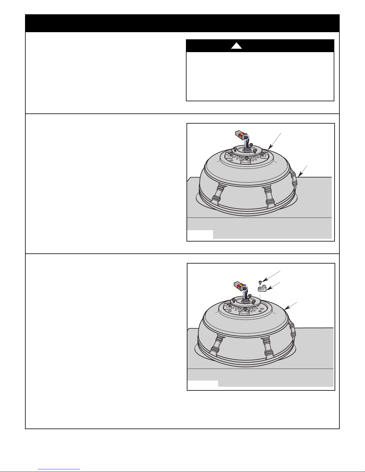
BOTTOM
FOAM PAD
FAN ASSEMBLY
FAN ASSEMBLY
SHIPPING SPACER
SHIPPING SPACER
SCREW
3.1
Disconnect electrical power to the branch circuit at the
circuit breaker or fuse box before attempting to install
he ceiling fan mounting plate on the outlet box.
t
3.2
Remo v e the f a n ass e mbly f rom th e prot e ctiv e
plastic bag. Place the fan assembly into the bottom
foam pad with the bottom of the fan assembly motor
facing up (Figure 1).
The bottom foam pad serves as a holder for the fan
during the first stages of assembly.
Turning off wall switch is not sufficient. To avoid
ossible electrical shock, be sure electricity is turned
p
off at the main fuse box before wiring. All wiring must
be in accordance with National and Local codes and
the ceiling fan must be properly groun d e d a s a
precaution against possible electrical shock.
!
WARNING
3.3
Remo v e th e sh i ppin g spa c ers a nd t he s p acer
attachment screws from the motor before installation of
blade assemblies (Figure 2).
Discard the spacers and spacer screws.
Figure 1
Figure 2
emersonfans.com
Please contact 1-800-654-3545 for further assistance
5
E.T.L. Model No.: CF610
3. Ceiling Fan Assembly (Continued)
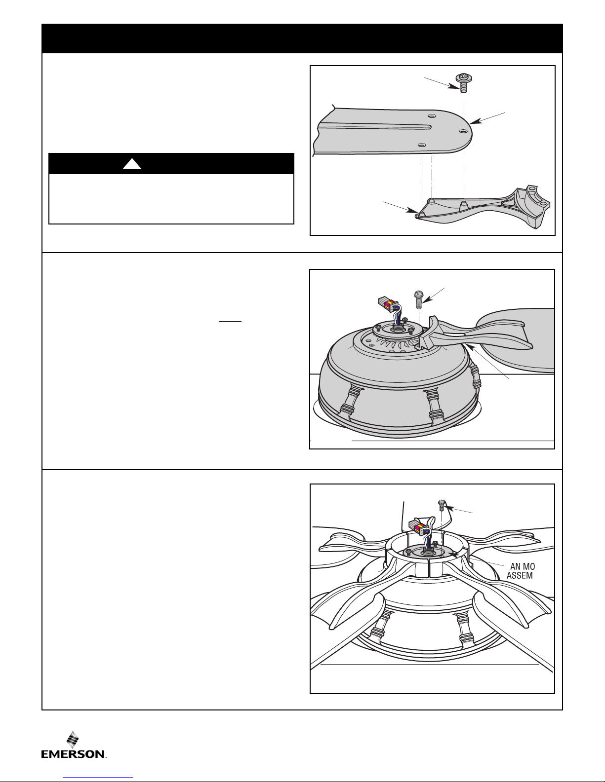
1/4-20 x 1/2" ROUND HEAD
SCREW WITH LOCKWASHER
(2 per blade assembly)
BLADE/FLANGE
ASSEMBLY (5)
REMOVE ONE
#8-32 x 5/16" ROUND
HEAD SCREW
OR
FAN BLADE
BLADE FLANGE
#10-32 x 5/16" WASHER
HEAD SCREW (3)
3.4
Mount the blade flange to the fan blade using three
#10- 3 2 x 5/16 ” w ashe r h ead sc r ews (sup p lie d )
Figure 3).
(
Repeat this procedure for other four fan blades and
blade flanges.
WARNING
To reduce the risk of personal injury, do not bend the
blade fl a n g e when ins t a l ling the b l a d e f lange s ,
balancing the blades or cleaning the fan. Do not insert
foreign objects in between rotating fan blades
!
3.5
Attach one blade assembly to the motor hub using two
1/4-20 x 1/2” round head screws with lockwashers in
flange. Make sure the screws are NOT tightened.
(Figure 4.)
Repe a t this pr oced u re for t h e othe r f our bl a de
assemblies.
NOTE: The blade flanges have an interlocking
feat u re t h at m u st b e ful l y en g age d bef o re
tightening the screws. Make sure all the flanges are
pr o p e r l y engaged and then tighten the flange
screws. If one of the flanges does not seat properly
on t h e m o t o r h u b , l o o s e n t h e adjacent flange
screws, re-engage and reseat the flanges, then
tighten the screws again.
Figure 3
Figure 4
3.6
Remove one of the three #8-32 x 5/16” round head
screws from the fan motor assembly (Figure 5). Retain
the screw for future installation.
Loosen the other two screws several turns.
Pass the fan motor assembly’s black, blue and white
leads through the center hole of the switch housing
adapter.
Position the switch housing adapter on the motor
assembly and align the holes in the switch housing
adapter with the screws on the adapter.
NOTE: Do not pinch wires between the switch
housing assembly and the switch housing adapter.
Spare #8-32 x 5/16” round head screw is provided in
parts bag if needed.
E.T.L. Model No.: CF610
Figure 5
6

SWITCH HOUSING #8-32 x 5/16"
FLAT HEAD SCREW (3)
SWITCH
HOUSING
ASSEMBLY
3. Ceiling Fan Assembly (Continued)
SWITCH HOUSING
ASSEMBLY
SWITCH HOUSING
ASSEMBLY
CONNECTOR
FAN MOTOR
CONNECTOR
REPLACE ONE
#8-32 x 5/16" ROUND
HEAD SCREW
FAN MOTOR
ASSEMBLY
TCH
ADAPTER
ROTATE SWITCH
HOUSING ADAPTER
CLOCKWISE TO
SECURE
3.7
otate the switch housing adapter on the fan motor
R
assembly by engaging the keyhole slots of the switch
housing adapter with the loosened screw heads on the
fan motor assembly (Figure 6).
With the switch housing adapter locked into position,
tighten the two previously loosened screws.
Rein s tal l the #8 -32 x 5/1 6 ” ro u nd h ead s crew
(previously removed in Step 3.6) to secure the switch
housing adapter (Figure 6).
3.8
Remove the three #8-32 x 5/16” flat head screws
(Figure 7) from the switch housing assembly.
Retain the screws for future use in Step 3.10.
Figure 6
Spare #8-32 x 5/16” flat head screw is provided in parts
bag if needed.
NOTE: If you are using an Emerson light fixture
with your fan. Remove the screw plug from the
bottom of the switch housing cover and install the
lig h t i n a c c o r d a n c e w i t h t h e l i g h t k i t O w n e r ' s
Manual. Make light kit electrical connections to blue
and white leads marked “For Light” in the switch
housing assembly. Follow light kit instructions for
wiring a n d install a t ion. The n r einstal l s witch
housing as outlined above.
3.9
Engage the connector of the switch housing assembly
with the fan motor connector (Figure 8).
The two connectors are keyed and color-coded and
must be mated correctly (color-to-color) before they can
be engaged. Make sure the connector latch closes
properly.
Figure 7
Figure 8
emersonfans.com
Please contact 1-800-654-3545 for further assistance
7
E.T.L. Model No.: CF610

SETSCREW
(LOOSENED)
HANGER BALL
4.5" DOWNROD
PIN
GREEN
GROUND
WIRE
3. Ceiling Fan Assembly (Continued)
SWITCH
HOUSING
ASSEMBLY
R
EINSTALL SWITCH HOUSING #8-32 x 5/16"
FLAT HEAD SCREW (3)
3.10
osition the switch housing assembly on the switch
P
housing adapter and align the holes in the switch
housing assembly with the holes in the adapter.
Secure the switch housing assembly by reinstalling
the three #8-32 x 5/16” flat head screws (previously
removed in Step 3.8) (Figure 9).
NO TE: Do not pin c h wires betwe en the switch
housing assembly and the switch housing adapter.
Figure 9
3.11
Carefully turn partially assembled fan upside down and
place in styrofoam carton, in preparation for final
installation.
Remove the hanger ball by loosening the setscrew in
the hanger ball until the ball falls freely down the
downrod (Figure 10).
Remove the pin from the downrod, then remove the
hanger ball.
Retain the pin and hanger ball for reinstallation in
Step 3.17.
NOTE: Do not loosen the screw holding the green
ground wire.
Figure 10
E.T.L. Model No.: CF610
8
 Loading...