

Page 1

Reference Manual
00809-0100-4808, Rev CA
June 2008
Rosemount 3051N Smart Pressure Transmitter for Nuclear Service
www.rosemountnuclear.com
Page 2

IMPOR TANT NOTICE -- ERRATA
Model 3051N Product Manual 00809-0100-4808 Rev CA (6/2008)
No. Affected Pages Description of Change
1 5-8 Flange Bolts and Mounting Bolts - Carbon steel, per
ASTM A449 Type 1 or SAE J429 Grade 5…
2 5-8 Electronics Housing – Low copper aluminum with
polyurethane paint, or CF-8M (cast version of 316
SST)...
3 5-8
Mounting Bracket – AISI 1010 steel or JIS G3131
SPHC P/O Steel with polyurethane paint (Option Code
B2)...
Effect.
Date
12/3/07
11/18/08
1/24/11
12/5/07
Page 3

Reference Manual
Rosemount Nuclear Instruments, Inc.
8200 Market Blvd.
Chanhassen, Mn 55317
Tel 952-949-5210
Fax 952-949-5201
©Rosemount Nuclear Instruments, Inc.
www.rosemountnuclear.com
Rosemount Nuclear Instruments, Inc.
satisfies all obligations coming from
legislation to harmonize product
requirements in the European Union.
00809-0100-4808, Rev CA
June 2008
Rosemount 3051N
Rosemount 3051N Smart Pressure Transmitter for Nuclear Service
Rosemount 3051 HART Universal Revision 5
NOTICE
Read this manual before working with the product. For personal and system
safety, and for optimum product performance, make sure you thoroughly
understand the contents before installing, using, or maintaining this product.
Within the United States, contact Rosemount Nuclear Instruments, Inc. at
1-952-949-5210 for assistance.
Outside of the United States, contact your local Emerson Process
Management Sales Representative.
The Rosemount logotype, and SMART FAMILY are registered trademarks of Rosemount Inc.
Coplanar is a trademark of Rosemount Inc.
Teflon is a registered trademark of E.I. du Pont de Nemours & Co.
D.C. 200 is a registered trademark of Dow Corning Corporation.
HART is a registered trademark of the HART Communication Foundation.
www.rosemountnuclear.com
Page 4

Reference Manual
00809-0100-4808, Rev CA
Rosemount 3051N
June 2008
Rosemount Nuclear Instruments, Inc. Warranty and Limitations of Remedy
The warranty and limitations of remedy applicable to this Rosemount equipment are as stated on the reverse of the
current Rosemount quotation and customer acknowledgment forms.
RETURN OF MATERIAL
Authorization for return is required from Rosemount Nuclear Instruments, Inc. prior to shipment. Contact Rosemount Nuclear Instruments,
Inc. (1-952-949-5210) for details on obtaining Return Material Authorization (RMA). Rosemount Nuclear Instruments will not accept
any returned material without a Returned Material Authorization. Material returned without authorization is subject to return to
customer.
Material returned for repair, whether in or out of warranty, should be shipped prepaid to:
Rosemount Nuclear Instruments, Inc.
8200 Market Blvd.
Chanhassen, MN 55317
USA
IMPORTANT
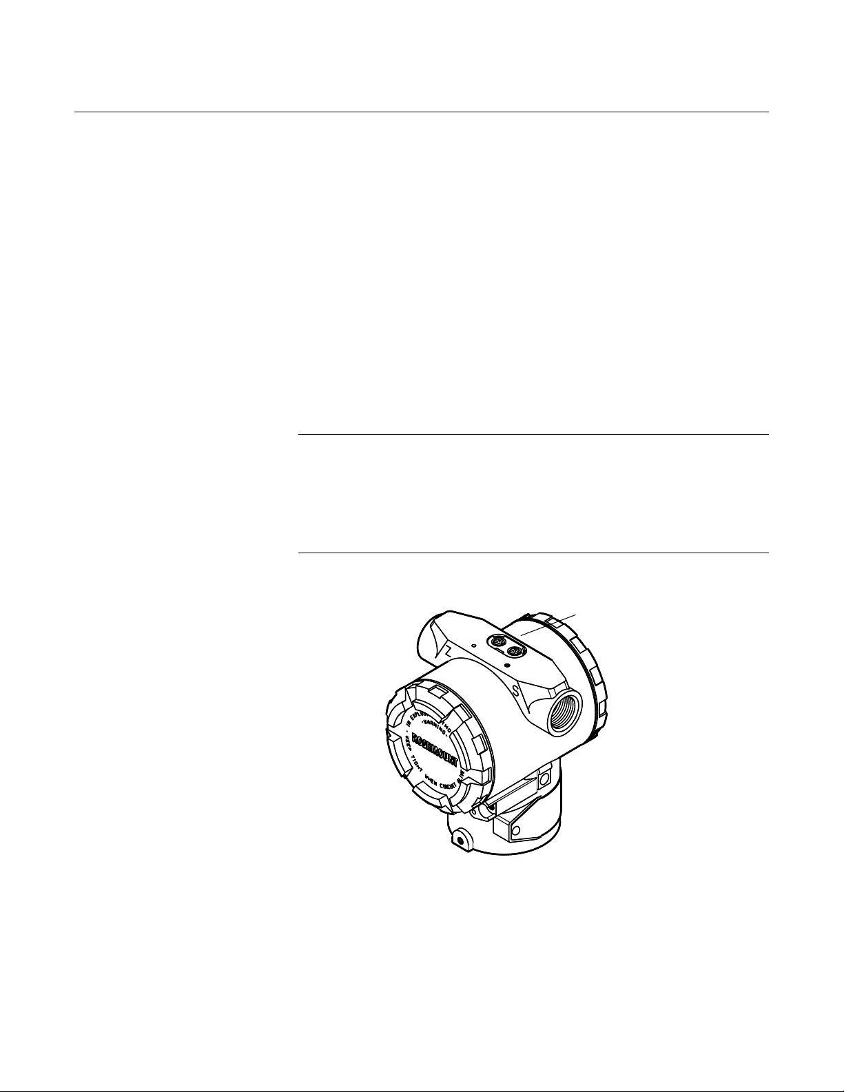
The Rosemount 3051N Pressure Transmitter is qualified for nuclear use per IEEE Std 344-1987 and IEEE Std 323-1983 (mild
environment) as documented in Rosemount Report D2001019, and is supplied in accordance with 10CFR50 Appendix B and ISO
9001:2000 quality assurance programs. To ensure compliance with 10CFR Part 21, the transmitter must comply with the requirements
herein and in Report D2001019 throughout its installation, operation, and maintenance. It is incumbent upon the user to ensure that the
Rosemount Nuclear Instruments, Inc. component traceability program where applicable is continued throughout the life of the transmitter.
Where the manual uses the terms requirements, mandatory, must, or required, the instructions so referenced must be carefully followed.
Rosemount Nuclear Instruments, Inc. expressly disclaims all responsibility and liability for transmitters for which the foregoing has not
been complied with by the user.
ii
Page 5

Reference Manual
00809-0100-4808, Rev CA
June 2008
Rosemount 3051N
Revision Status
Changes from June 2006 to June 2008
Page (Old) Page (New) Changes
Cover,
throughout
TOC-1 Page i, back
- Page iii Add Revision Status page
TOC-1 to TOC-8 i to iv and TOC-1
Throughout Throughout Manual number corrected to 00809-0100-4808
3-6 and 3-8 3-6 and 3-8 Changed significant digits to conform to standard
3-12 3-12 Removed word ‘process’ from sentences indicating user responsibility for qualifying the connection
5-7 5-8 Reworded flange bolt description to reflect qualification configuration
NOTE
The above Revision Status list summarizes the changes made. Please refer to both manuals for complete
comparison details.
Cover,
throughout
cover
to TOC-4
Document revision date change from June 2006 to June 2008,
rev from BA to CA
CE mark added with Rosemount Nuclear Instruments, Inc.
Page numbers changed
interface
www.rosemountnuclear.com
Page 6

Rosemount 3051N
Reference Manual
00809-0100-4808, Rev CA
June 2008
iv
Page 7

Reference Manual
00809-0100-4808, Rev CA
June 2008
Rosemount 3051N
Table of Contents
SECTION 1
Introduction
SECTION 2
Transmitter Functions
Using This Manual . . . . . . . . . . . . . . . . . . . . . . . . . . . . . . . . . . . . . . . . 1-1
Overview . . . . . . . . . . . . . . . . . . . . . . . . . . . . . . . . . . . . . . . . . . . . . . . 2-1
Safety Messages . . . . . . . . . . . . . . . . . . . . . . . . . . . . . . . . . . . . . . . . . 2-1
Warnings . . . . . . . . . . . . . . . . . . . . . . . . . . . . . . . . . . . . . . . . . . . . 2-1
Failure Mode Alarm . . . . . . . . . . . . . . . . . . . . . . . . . . . . . . . . . . . . . . . 2-2
Alarm Level Verification . . . . . . . . . . . . . . . . . . . . . . . . . . . . . . . . . 2-2
Transmitter Security. . . . . . . . . . . . . . . . . . . . . . . . . . . . . . . . . . . . . . . 2-2
Security Jumper (Write Protect) . . . . . . . . . . . . . . . . . . . . . . . . . . . 2-3
Local Zero and Span (Local Keys) Software Lock Out. . . . . . . . . . 2-3
Physical Removal of Local Zero and Span (Local Keys) . . . . . . . . 2-3
Configuring Transmitter Alarm
and Security Jumper Procedure . . . . . . . . . . . . . . . . . . . . . . . . . . . . . 2-3
Commissioning the Rosemount 3051N with a
HART-Based Communicator . . . . . . . . . . . . . . . . . . . . . . . . . . . . . . . . 2-4
Setting the Loop to Manual. . . . . . . . . . . . . . . . . . . . . . . . . . . . . . . 2-5
Wiring Diagrams (Bench Hook-up). . . . . . . . . . . . . . . . . . . . . . . . . 2-5
Wiring Diagrams (Field Hook-up) . . . . . . . . . . . . . . . . . . . . . . . . . . 2-6
Review Configuration Data . . . . . . . . . . . . . . . . . . . . . . . . . . . . . . . . . 2-7
Check Output. . . . . . . . . . . . . . . . . . . . . . . . . . . . . . . . . . . . . . . . . . . . 2-7
Process Variables. . . . . . . . . . . . . . . . . . . . . . . . . . . . . . . . . . . . . . 2-7
Sensor Temperature. . . . . . . . . . . . . . . . . . . . . . . . . . . . . . . . . . . . 2-8
Basic Setup . . . . . . . . . . . . . . . . . . . . . . . . . . . . . . . . . . . . . . . . . . . . . 2-8
Set Process Variable Units. . . . . . . . . . . . . . . . . . . . . . . . . . . . . . . 2-8
Set Output . . . . . . . . . . . . . . . . . . . . . . . . . . . . . . . . . . . . . . . . . . . 2-8
Rerange . . . . . . . . . . . . . . . . . . . . . . . . . . . . . . . . . . . . . . . . . . . . . 2-9
Rerange with a Communicator Only. . . . . . . . . . . . . . . . . . . . . . . . 2-9
Rerange with a Pressure Input Source and a Communicator . . . 2-10
Rerange with a Pressure Input Source and
the Local Zero and Span Buttons . . . . . . . . . . . . . . . . . . . . . . . . . 2-10
Damping . . . . . . . . . . . . . . . . . . . . . . . . . . . . . . . . . . . . . . . . . . . . 2-12
LCD Meter Options. . . . . . . . . . . . . . . . . . . . . . . . . . . . . . . . . . . . 2-12
Detailed Setup . . . . . . . . . . . . . . . . . . . . . . . . . . . . . . . . . . . . . . . . . . 2-12
Local Span and Zero Control (Local Keys). . . . . . . . . . . . . . . . . . 2-12
Sensor Temperature Output Unit Selection . . . . . . . . . . . . . . . . . 2-12
Diagnostics and Service . . . . . . . . . . . . . . . . . . . . . . . . . . . . . . . . . . 2-12
Transmitter Test . . . . . . . . . . . . . . . . . . . . . . . . . . . . . . . . . . . . . . 2-13
Loop Test . . . . . . . . . . . . . . . . . . . . . . . . . . . . . . . . . . . . . . . . . . . 2-13
Calibration . . . . . . . . . . . . . . . . . . . . . . . . . . . . . . . . . . . . . . . . . . . . . 2-13
Calibration Overview . . . . . . . . . . . . . . . . . . . . . . . . . . . . . . . . . . 2-15
Deciding Which Trim Procedure to Use . . . . . . . . . . . . . . . . . . . . 2-16
Sensor Trim . . . . . . . . . . . . . . . . . . . . . . . . . . . . . . . . . . . . . . . . . 2-16
www.rosemountnuclear.com
Page 8

Rosemount 3051N
Reference Manual
00809-0100-4808, Rev CA
June 2008
Zero Trim . . . . . . . . . . . . . . . . . . . . . . . . . . . . . . . . . . . . . . . . . . . 2-17
Full Trim . . . . . . . . . . . . . . . . . . . . . . . . . . . . . . . . . . . . . . . . . . . . 2-18
Recall Factory Trim . . . . . . . . . . . . . . . . . . . . . . . . . . . . . . . . . . . 2-19
Recall Factory Trim— Sensor Trim . . . . . . . . . . . . . . . . . . . . . . . 2-19
Recall Factory Trim— Analog Output. . . . . . . . . . . . . . . . . . . . . . 2-19
Analog Output Trim . . . . . . . . . . . . . . . . . . . . . . . . . . . . . . . . . . . 2-19
Digital-to-Analog Trim. . . . . . . . . . . . . . . . . . . . . . . . . . . . . . . . . . 2-19
Digital-to-Analog Trim Using Other Scale. . . . . . . . . . . . . . . . . . . 2-19
Compensating Rosemount 3051N Range 4 and
5 Differential Transmitters for Line Pressure . . . . . . . . . . . . . . . . 2-20
SECTION 3
Installation
SECTION 4
Troubleshooting
SECTION 5
Specifications and
Reference Data
Overview . . . . . . . . . . . . . . . . . . . . . . . . . . . . . . . . . . . . . . . . . . . . . . . 3-1
Safety Messages . . . . . . . . . . . . . . . . . . . . . . . . . . . . . . . . . . . . . . . . . 3-1
Warnings . . . . . . . . . . . . . . . . . . . . . . . . . . . . . . . . . . . . . . . . . . . . 3-1
General Considerations . . . . . . . . . . . . . . . . . . . . . . . . . . . . . . . . . . . . 3-4
Special Draft Range Considerations . . . . . . . . . . . . . . . . . . . . . . . 3-4
Mechanical Considerations . . . . . . . . . . . . . . . . . . . . . . . . . . . . . . . . . 3-4
Mounting. . . . . . . . . . . . . . . . . . . . . . . . . . . . . . . . . . . . . . . . . . . . . 3-9
Process Connections . . . . . . . . . . . . . . . . . . . . . . . . . . . . . . . . . . 3-12
Housing Rotation . . . . . . . . . . . . . . . . . . . . . . . . . . . . . . . . . . . . . 3-12
Electrical Considerations . . . . . . . . . . . . . . . . . . . . . . . . . . . . . . . . . . 3-12
Power Supply . . . . . . . . . . . . . . . . . . . . . . . . . . . . . . . . . . . . . . . . 3-12
Wiring . . . . . . . . . . . . . . . . . . . . . . . . . . . . . . . . . . . . . . . . . . . . . . 3-13
Grounding the Transmitter Case . . . . . . . . . . . . . . . . . . . . . . . . . 3-14
Environmental Considerations. . . . . . . . . . . . . . . . . . . . . . . . . . . . . . 3-14
Access Requirements. . . . . . . . . . . . . . . . . . . . . . . . . . . . . . . . . . 3-14
Cover Installation . . . . . . . . . . . . . . . . . . . . . . . . . . . . . . . . . . . . . 3-14
Overview . . . . . . . . . . . . . . . . . . . . . . . . . . . . . . . . . . . . . . . . . . . . . . . 4-1
Safety Messages . . . . . . . . . . . . . . . . . . . . . . . . . . . . . . . . . . . . . . . . . 4-1
Warnings . . . . . . . . . . . . . . . . . . . . . . . . . . . . . . . . . . . . . . . . . . . . 4-1
Returning Rosemount Products and Materials. . . . . . . . . . . . . . . . 4-2
Nuclear Specifications . . . . . . . . . . . . . . . . . . . . . . . . . . . . . . . . . . . . . 5-1
Seismic . . . . . . . . . . . . . . . . . . . . . . . . . . . . . . . . . . . . . . . . . . . . . . 5-1
Environmental. . . . . . . . . . . . . . . . . . . . . . . . . . . . . . . . . . . . . . . . . 5-2
Quality Assurance Program . . . . . . . . . . . . . . . . . . . . . . . . . . . . . . 5-2
Nuclear Cleaning . . . . . . . . . . . . . . . . . . . . . . . . . . . . . . . . . . . . . . 5-2
Hydrostatic Testing. . . . . . . . . . . . . . . . . . . . . . . . . . . . . . . . . . . . . 5-2
Performance Specifications . . . . . . . . . . . . . . . . . . . . . . . . . . . . . . . . . 5-3
Reference Accuracy . . . . . . . . . . . . . . . . . . . . . . . . . . . . . . . . . . . . 5-3
Drift . . . . . . . . . . . . . . . . . . . . . . . . . . . . . . . . . . . . . . . . . . . . . . . . . 5-3
Ambient Temperature Effect. . . . . . . . . . . . . . . . . . . . . . . . . . . . . . 5-3
Overpressure Effect . . . . . . . . . . . . . . . . . . . . . . . . . . . . . . . . . . . . 5-4
Static Pressure Effect . . . . . . . . . . . . . . . . . . . . . . . . . . . . . . . . . . . 5-4
Power Supply Effect . . . . . . . . . . . . . . . . . . . . . . . . . . . . . . . . . . . . 5-4
Load Effect . . . . . . . . . . . . . . . . . . . . . . . . . . . . . . . . . . . . . . . . . . . 5-4
Mounting Position Effect. . . . . . . . . . . . . . . . . . . . . . . . . . . . . . . . . 5-4
Functional Specifications . . . . . . . . . . . . . . . . . . . . . . . . . . . . . . . . . . . 5-5
Service . . . . . . . . . . . . . . . . . . . . . . . . . . . . . . . . . . . . . . . . . . . . . . 5-5
Output. . . . . . . . . . . . . . . . . . . . . . . . . . . . . . . . . . . . . . . . . . . . . . . 5-5
Power Supply . . . . . . . . . . . . . . . . . . . . . . . . . . . . . . . . . . . . . . . . . 5-5
TOC-2
Page 9

Reference Manual
00809-0100-4808, Rev CA
June 2008
Rosemount 3051N
Temperature Limits. . . . . . . . . . . . . . . . . . . . . . . . . . . . . . . . . . . . . 5-5
Span and Zero, Zero Elevation, and Suppression . . . . . . . . . . . . . 5-6
Humidity Limits . . . . . . . . . . . . . . . . . . . . . . . . . . . . . . . . . . . . . . . . 5-6
Volumetric Displacement . . . . . . . . . . . . . . . . . . . . . . . . . . . . . . . . 5-6
Turn-on Time . . . . . . . . . . . . . . . . . . . . . . . . . . . . . . . . . . . . . . . . . 5-6
Response Time . . . . . . . . . . . . . . . . . . . . . . . . . . . . . . . . . . . . . . . 5-6
Maximum Working Pressure . . . . . . . . . . . . . . . . . . . . . . . . . . . . . 5-7
Static Pressure Limits. . . . . . . . . . . . . . . . . . . . . . . . . . . . . . . . . . . 5-7
Overpressure Limits . . . . . . . . . . . . . . . . . . . . . . . . . . . . . . . . . . . . 5-7
Burst Pressure . . . . . . . . . . . . . . . . . . . . . . . . . . . . . . . . . . . . . . . . 5-7
Physical Specifications . . . . . . . . . . . . . . . . . . . . . . . . . . . . . . . . . . . . 5-8
Materials of Construction . . . . . . . . . . . . . . . . . . . . . . . . . . . . . . . . . . . 5-8
Ordering Information . . . . . . . . . . . . . . . . . . . . . . . . . . . . . . . . . . . . . 5-10
Configuration Information . . . . . . . . . . . . . . . . . . . . . . . . . . . . . . . . . 5-11
Rosemount 3051N 4-20 mA/HART Output Smart
Pressure Transmitters Typical Configuration Data Worksheet . . . . . 5-12
SECTION 6
Options
APPENDIX A
HART Communicator
Overview . . . . . . . . . . . . . . . . . . . . . . . . . . . . . . . . . . . . . . . . . . . . . . . 6-1
Safety Messages . . . . . . . . . . . . . . . . . . . . . . . . . . . . . . . . . . . . . . . . . 6-1
Warnings . . . . . . . . . . . . . . . . . . . . . . . . . . . . . . . . . . . . . . . . . . . . 6-1
LCD Meter . . . . . . . . . . . . . . . . . . . . . . . . . . . . . . . . . . . . . . . . . . . . . . 6-1
Custom Meter Configuration. . . . . . . . . . . . . . . . . . . . . . . . . . . . . . 6-2
Installing the Meter . . . . . . . . . . . . . . . . . . . . . . . . . . . . . . . . . . . . . 6-3
Diagnostic Messages . . . . . . . . . . . . . . . . . . . . . . . . . . . . . . . . . . . 6-5
Error . . . . . . . . . . . . . . . . . . . . . . . . . . . . . . . . . . . . . . . . . . . . . . . . 6-5
Warnings . . . . . . . . . . . . . . . . . . . . . . . . . . . . . . . . . . . . . . . . . . . . 6-6
Operation . . . . . . . . . . . . . . . . . . . . . . . . . . . . . . . . . . . . . . . . . . . . 6-7
Mounting Brackets . . . . . . . . . . . . . . . . . . . . . . . . . . . . . . . . . . . . . . . . 6-7
Traditional Flange (H2). . . . . . . . . . . . . . . . . . . . . . . . . . . . . . . . . . 6-8
Transient Protection Terminal Block (T1) . . . . . . . . . . . . . . . . . . . . . . 6-8
Introduction . . . . . . . . . . . . . . . . . . . . . . . . . . . . . . . . . . . . . . . . . . . . . A-1
Safety Messages . . . . . . . . . . . . . . . . . . . . . . . . . . . . . . . . . . . . . . . . . A-1
Warnings . . . . . . . . . . . . . . . . . . . . . . . . . . . . . . . . . . . . . . . . . . . .A-2
Connections and Hardware . . . . . . . . . . . . . . . . . . . . . . . . . . . . . . . . . A-5
Rosemount 275 . . . . . . . . . . . . . . . . . . . . . . . . . . . . . . . . . . . . . . . . . .A-7
Communicator Keys . . . . . . . . . . . . . . . . . . . . . . . . . . . . . . . . . . . . A-7
Action Keys. . . . . . . . . . . . . . . . . . . . . . . . . . . . . . . . . . . . . . . . . . . A-7
Function Keys. . . . . . . . . . . . . . . . . . . . . . . . . . . . . . . . . . . . . . . . . A-8
Alphanumeric and Shift Keys . . . . . . . . . . . . . . . . . . . . . . . . . . . . .A-8
Data Entry. . . . . . . . . . . . . . . . . . . . . . . . . . . . . . . . . . . . . . . . . . . . A-8
Fast Key Sequences . . . . . . . . . . . . . . . . . . . . . . . . . . . . . . . . . . .A-9
Fast Key Sequence Conventions . . . . . . . . . . . . . . . . . . . . . . . . . . A-9
Fast Key Sequence Example . . . . . . . . . . . . . . . . . . . . . . . . . . . . . A-9
Menus and Functions . . . . . . . . . . . . . . . . . . . . . . . . . . . . . . . . . . . . .A-9
Main Menu . . . . . . . . . . . . . . . . . . . . . . . . . . . . . . . . . . . . . . . . . . . A-9
Online Menu . . . . . . . . . . . . . . . . . . . . . . . . . . . . . . . . . . . . . . . . . A-10
Rosemount 375 . . . . . . . . . . . . . . . . . . . . . . . . . . . . . . . . . . . . . . . . .A-11
Communicator Keys . . . . . . . . . . . . . . . . . . . . . . . . . . . . . . . . . . . A-11
Action Keys. . . . . . . . . . . . . . . . . . . . . . . . . . . . . . . . . . . . . . . . . . A-11
Alphanumeric Keys. . . . . . . . . . . . . . . . . . . . . . . . . . . . . . . . . . . . A-12
Function Key. . . . . . . . . . . . . . . . . . . . . . . . . . . . . . . . . . . . . . . . . A-12
TOC-3
Page 10

Rosemount 3051N
Glossary
Index
Reference Manual
00809-0100-4808, Rev CA
June 2008
Multifunction LED . . . . . . . . . . . . . . . . . . . . . . . . . . . . . . . . . . . . .A-12
Touch Screen . . . . . . . . . . . . . . . . . . . . . . . . . . . . . . . . . . . . . . . . A-12
Using the Soft Input Panel (SIP) keyboard. . . . . . . . . . . . . . . . . . A-13
Menus and Functions . . . . . . . . . . . . . . . . . . . . . . . . . . . . . . . . . . A-13
HART Application Startup. . . . . . . . . . . . . . . . . . . . . . . . . . . . . . . A-13
Main Menu . . . . . . . . . . . . . . . . . . . . . . . . . . . . . . . . . . . . . . . . . . A-13
Fast Key Sequences . . . . . . . . . . . . . . . . . . . . . . . . . . . . . . . . . .A-14
Hot Key options . . . . . . . . . . . . . . . . . . . . . . . . . . . . . . . . . . . . . . A-14
Diagnostic Messages. . . . . . . . . . . . . . . . . . . . . . . . . . . . . . . . . . . . . A-14
TOC-4
Page 11

Reference Manual
00809-0100-4808, Rev CA
June 2008
Rosemount 3051N
Section 1 Introduction
USING THIS MANUAL The sections in this manual provide information on installing, operating, and
maintaining devices from the Rosemount 3051N Smart Pressure Transmitter
Family. The sections are organized as follows:
Section 2: Transmitter Functions
Provides instruction on commissioning and operating Rosemount 3051N
Pressure Transmitters. Information on software functions, configuration
parameters, and on-line variables is also included.
Section 3: Installation
Contains mechanical and electrical installation instructions.
Section 4: Troubleshooting
Provides troubleshooting techniques for the most common Rosemount 3051N
transmitter operating problems.
Section 5: Specifications and Reference Data
Supplies reference and specification data for the Rosemount 3051N Smart
Pressure Transmitter Family.
Section 6: Options
Describes the mounting and configuration options available for Rosemount
3051N transmitters.
Appendix A: HART Communicator
Gives an overview of the HART Communicator, defines its partial command
menu tree for the Rosemount 3051N family, and provides a table of typical
fast key sequences. A table of typical diagnostic messages is also included.
www.rosemountnuclear.com
Page 12

Rosemount 3051N
Reference Manual
00809-0100-4808, Rev CA
June 2008
1-2
Page 13

Reference Manual
00809-0100-4808, Rev CA
June 2008
Rosemount 3051N
Section 2 Transmitter Functions
Overview . . . . . . . . . . . . . . . . . . . . . . . . . . . . . . . . . . . . . . . page 2-1
Safety Messages . . . . . . . . . . . . . . . . . . . . . . . . . . . . . . . . . page 2-1
Failure Mode Alarm . . . . . . . . . . . . . . . . . . . . . . . . . . . . . . page 2-2
Review Configuration Data . . . . . . . . . . . . . . . . . . . . . . . . page 2-7
Check Output . . . . . . . . . . . . . . . . . . . . . . . . . . . . . . . . . . . page 2-7
Basic Setup . . . . . . . . . . . . . . . . . . . . . . . . . . . . . . . . . . . . . page 2-8
Detailed Setup . . . . . . . . . . . . . . . . . . . . . . . . . . . . . . . . . . . page 2-12
Diagnostics and Service . . . . . . . . . . . . . . . . . . . . . . . . . . page 2-12
Calibration . . . . . . . . . . . . . . . . . . . . . . . . . . . . . . . . . . . . . . page 2-13
OVERVIEW This section contains information on commissioning and operating
Rosemount 3051N Smart Pressure Transmitters. Tasks that should be
performed on the bench prior to installation are explained in this section.
When the HART Communicator is referenced, it refers to either the
Rosemount 275 or Rosemount 375 as documented in Rosemount Report
D2001019.
For your convenience, typical HART Communicator fast key sequences are
listed for most software functions. These fast key sequences are the same for
both the Rosemount 275 and Rosemount 375 Communicators. If you are
unfamiliar with the communicator or how to follow fast key sequences, please
refer to Appendix A for communicator operations.
A typical transmitter software configuration data worksheet is provided in
Section 5.
SAFETY MESSAGES Procedures and instructions in this section may require special precautions to
ensure the safety of the personnel performing the operations. Information that
raises potential safety issues is indicated by a warning symbol ( ). Refer to
the following safety messages before performing an operation preceded by
this symbol.
Warnings
Explosions can result in death or serious injury.
• Do not remove the transmitter covers in explosive environments when the
circuit is alive.
www.rosemountnuclear.com
Page 14
Reference Manual
00809-0100-4808, Rev CA
Rosemount 3051N
Electrical shock can result in death or serious injury.
• Avoid contact with the leads and terminals. High voltage that may be present
on leads can cause electrical shock.
June 2008
FAILURE MODE ALARM Rosemount 3051N transmitters automatically and continuously perform
self-diagnostic routines. If the self-diagnostic routines detect a failure, the
transmitter drives its output outside of the normal saturation values. The
transmitter will drive its output low or high based on the position of the failure
mode alarm jumper. See Table 2-1 for failure mode and saturation output
levels. To select alarm position, see “Configuring Transmitter Alarm and
Security Jumper Procedure” in Section 2.
Table 2-1. Standard Alarm and Saturation Values.
Level
4–20 mA
Saturation
4–20 mA
Alarm
Low 3.9 mA ≤ 3.75 mA
High 20.8 mA ≥ 21.75 mA
NOTE
You can alter the actual transmitter mA output values by performing an analog
output trim.
NOTE
When a transmitter is in an alarm condition, the hand-held HART
Communicator indicates the analog output the transmitter would drive if the
alarm condition did not exist. The transmitter will alarm high in the event of
failure if the alarm jumper is removed.
Alarm Level Verification Transmitters allow verification testing of alarm current levels. If you replace
the LCD meter, reconfigure or make any changes to the transmitter, verify the
transmitter alarm level before you return the transmitter to service. This
feature is also useful in testing the reaction of your control system to a
transmitter in an alarm state. To verify the transmitter alarm values, perform a
loop test and set the transmitter output to the alarm value (see Table 2-1 and
“Loop Test” in Section 2).
TRANSMITTER
There are three security methods with the Rosemount 3051N transmitter:
SECURITY
2-2
Page 15

Reference Manual
00809-0100-4808, Rev CA
June 2008
Rosemount 3051N
1. Security Jumper: prevents all writes to transmitter configuration.
2. Local Keys (Local Zero and Span) Software Lock Out: prevents changes to transmitter range points via local zero and span adjustment keys. With local keys security enabled, changes to configuration are possible via HART.
3. Physical Removal of Local Keys (Local Zero and Span) Magnetic Buttons: removes ability to use local keys to make transmitter range point adjustments. With local keys security enabled, changes to configuration are possible via HART.
NOTE
If the security jumper is not installed, the transmitter will continue to operate in
the security OFF configuration.
Security Jumper (Write Protect)
Local Zero and Span (Local Keys) Software Lock Out
Physical Removal of Local Zero and Span (Local Keys)
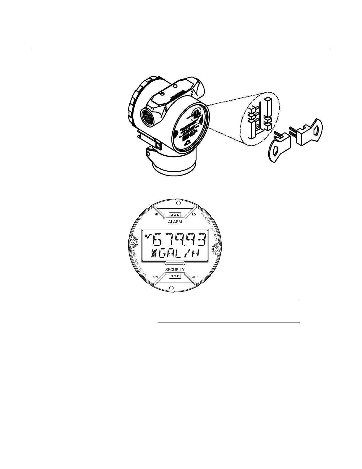
CONFIGURING TRANSMITTER ALARM AND SECURITY JUMPER PROCEDURE
You can prevent changes to the transmitter configuration data with the write
protection jumper. Security is controlled by the security (write protect) jumper
located on the electronics board or meter face. Position the jumper on the
transmitter circuit board in the “ON” position to prevent accidental or
deliberate change of configuration data.
If the transmitter write protection jumper is in the “ON” position, the transmitter
will not accept any “writes” to its memory. Configuration changes, such as
digital trim and reranging, cannot take place when the transmitter security is
on.
To enable this feature, see “Local Span and Zero Control (Local Keys)” in
Section 2.
To remove the magnetic buttons used to activate the local zero and span, use
a small slotted head screwdriver and pry off the small, plastic cap located
under the approval tag. Remove button assemblies and discard.
To reposition the jumpers, follow the procedure described below.
1. If the transmitter is installed, secure the loop and remove power.
2. Remove the housing cover opposite the field terminal side. Do not remove the transmitter covers in explosive atmospheres when the circuit is alive.
3. Reposition the jumpers as desired.
• Figure 2-1 shows the jumper positions for Electronics Boards.
• Figure 2-2 shows transmitters with an optional LCD meter.
4. Reattach the transmitter cover. Transmitter covers must be fully engaged to meet explosionproof requirements.
2-3
Page 16
Rosemount 3051N
ELECTRONICS BOARD
Alarm
Security
HI
LO
OFF
ON
NOTE
Security jumper not installed = Not Write Protected.
Alarm jumper not installed = High Alarm.
FIGURE 2-1. Electronics Board.
Reference Manual
00809-0100-4808, Rev CA
June 2008
FIGURE 2-2. Rosemount 3051N with Optional LCD Meter.
COMMISSIONING THE ROSEMOUNT 3051N WITH A HART-BASED COMMUNICATOR
Commissioning consists of testing the transmitter and verifying transmitter
configuration data. You may commission Rosemount 3051N transmitters
either before or after installation. Commissioning the transmitter on the bench
before installation using a HART-based Communicator ensures that all
transmitter components are in good working order and acquaints you with the
operation of the device.
2-4
Page 17
Reference Manual
See “Safety Messages” on page 2-1 for warning information.
24 V dc
Supply
R
L
≥ 250Ω
Current
Meter
00809-0100-4808, Rev CA
June 2008
Rosemount 3051N
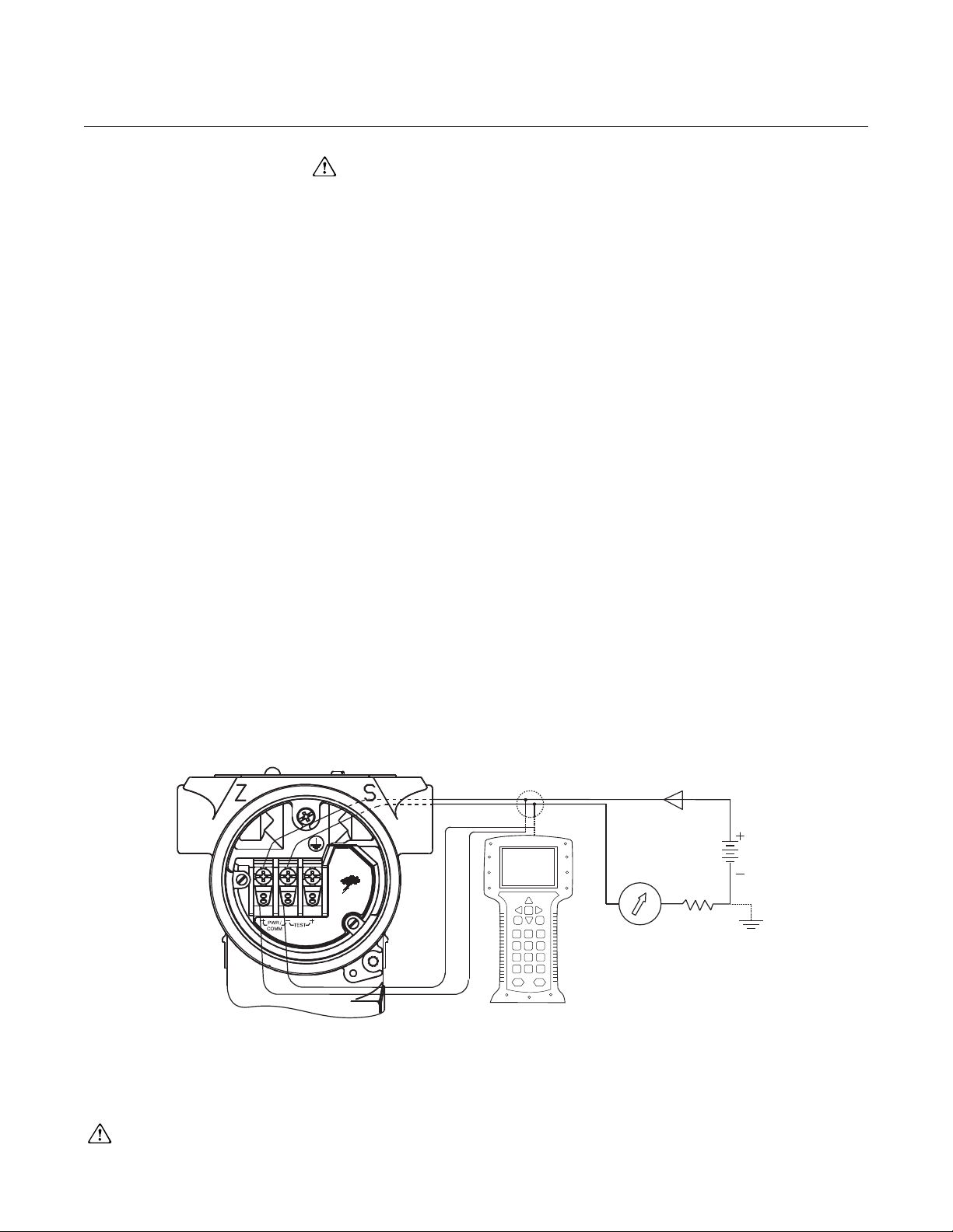
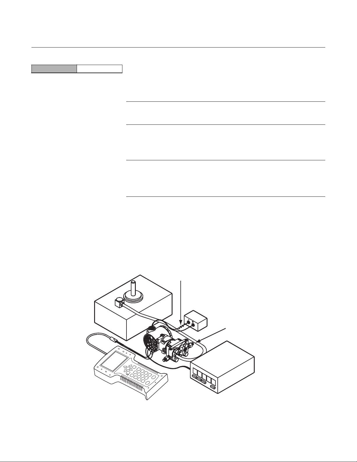
To commission on the bench, connect the transmitter and the communicator
as shown in Figure 2-3. Make sure the instruments in the loop are installed in
accordance with intrinsically safe or nonincendive field wiring practices before
connecting a communicator in an explosive atmosphere. Connect the
communicator leads at any termination point in the signal loop. It is most
convenient to connect them to the terminals labeled “COMM” on the terminal
block. Connecting across the “TEST” terminals will prevent successful
communication. To avoid exposing the transmitter electronics to the plant
environment after installation, set all transmitter jumpers during the
commissioning stage on the bench.
For 4–20 mA transmitters, you will need a power supply capable of providing
10.5 to 55 V dc at the transmitter, and a meter to measure output current. To
enable communication, a resistance of at least 250 ohms, but within the
transmitter load limitations (see Figure 3-7 “Power Supply Load Limitations.”
in Section 3) must be present between the communicator loop connection and
the power supply. Do not use inductive-based transient protectors with the
Rosemount 3051N.
Setting the Loop to Manual
Wiring Diagrams (Bench Hook-up)
FIGURE 2-3. Bench Hook-up (4–20 mA Transmitters).
Whenever you are preparing to send or request data that would disrupt the
loop or change the output of the transmitter, you must set your process
application loop to manual. The HART Communicator will prompt you to set
the loop to manual when necessary. Keep in mind that acknowledging this
prompt does not set the loop to manual. The prompt is only a reminder; you
have to set the loop to manual yourself as a separate operation.
Connect the bench equipment as shown in Figure 2-3 and turn on the
HART-based Communicator by pressing the ON/OFF key. The communicator
will search for a HART-compatible device and will indicate when the
connection is made. If the communicator fails to connect, it will indicate that
no device was found. If this occurs, refer to Section 4: Troubleshooting.
2-5
Page 18
Rosemount 3051N
Power
Supply
R
L
≥250Ω
Current
Meter
Signal point may be grounded at any
point or left ungrounded.
CAUTION
Do not use inductive-based
transient protectors.
Reference Manual
00809-0100-4808, Rev CA
June 2008
Wiring Diagrams (Field Hook-up)
FIGURE 2-4. Field Hook-up (4–20 mA Transmitters).
The following diagrams illustrate wiring loops for a field hook-up with a
HART-based Communicator.
2-6
Page 19

Reference Manual
00809-0100-4808, Rev CA
June 2008
Rosemount 3051N
REVIEW CONFIGURATION DATA
HART Comm 1, 5
NOTE
Information and procedures in this section that make use of HART
Communicator fast key sequences assume that the transmitter and
communicator are connected, powered, and operating correctly. If you are not
familiar with the HART Communicator or fast-key sequences, refer to
Appendix A: HART Communicator.
Before you place the transmitter into operation, it is recommended that you
review the transmitter configuration data that was set at the factory. You
should review the following configuration data:
Transmitter Model Type
Tag Range
Date Descriptor
Message Minimum and Maximum
Sensor Limits
Minimum Span Units
4 and 20 mA points Output (linear or sq. root)
Damping Alarm Setting (high, low)
Security Setting (on, off) Local Zero/Span Keys
(enabled, disabled)
Integral Meter Sensor Fill
Isolator Material Flange (type, material)
O-Ring Material Drain/Vent
Remote Seal (type, fill fluid,
isolator material, number)
Address Sensor S/N
Transmitter S/N
CHECK OUTPUT Before performing other transmitter on-line operations, review the digital
output parameters to ensure that the transmitter is operating properly and is
configured to the appropriate process variables.
Process Variables The process variables for the Rosemount 3051N provide the transmitter
HART Comm. 2
output, and are continuously updated. The process variable menu displays
the following process variables:
• Pressure
• Percent of Range
• Analog Output
The pressure reading in both Engineering Units and Percent of Range will
continue to track with pressures outside of the defined range from the lower to
the upper range limit of the sensor module.
2-7
Page 20

Reference Manual
00809-0100-4808, Rev CA
Rosemount 3051N
June 2008
NOTE
Regardless of the range points, the Rosemount 3051N will measure and
report all readings within the digital limits of the sensor. For example, if the
4 and 20 mA points are set to 0 and 10 in H
3051N, and the transmitter detects a pressure of 25 inH
the 25 inH
O reading and a 250% of span reading. However, there may be up
2
O on a range code 1 Rosemount
2
O, it digitally outputs
2
to ±5.0% error associated with output outside of the range points.
Sensor Temperature The Rosemount 3051N contains a temperature sensor just above its pressure
HART Comm. 1, 1, 4
sensor in the sensor module. When reading this temperature, keep in mind
that this is not a process temperature reading.
BASIC SETUP
Set Process Variable Units
HART Comm. 1, 3, 2
The PV Unit command sets the process variable units to allow you to monitor
your process using the appropriate units of measure. Select from the following
engineering units:
•inH2O•bar
• inHg • mbar
•ftH
O • g/cm
2
•mmH2O • kg/cm
2
2
•mmHg •Pa
•psi •kPa
• torr • atm
•inH
O at 4 °C • mmH2O at 4 °C
2
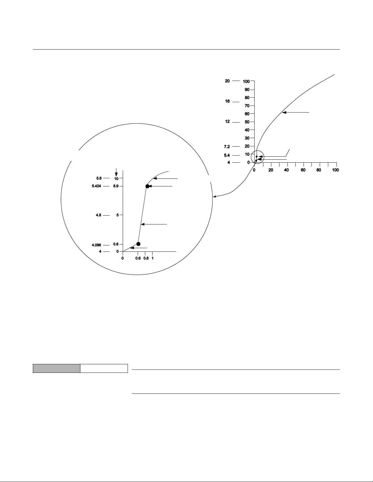
Set Output Activate the transmitter square root output option to make the analog output
HART Comm. 1, 3, 5
proportional to flow. As the input approaches zero, the Rosemount 3051N
automatically switches to a linear output in order to ensure a more smooth,
stable output near zero. See Figure 2-5.
The transition from linear to square root is not adjustable. It occurs at 0.8% of
ranged pressure input or 8.9% of full-scale flow output.
From 0 percent to 0.6 percent of the ranged pressure input, the slope of the
curve is unity (y = x). This allows accurate calibration near zero. Greater
slopes would cause large changes in output for small changes at input. From
0.6 percent to 0.8 percent, the slope of the curve equals 42 (y = 42x) to
achieve continuous transition from linear to square root at the transition point.
2-8
Page 21
Reference Manual
Sq. Root
Curve
Transition Point
Linear Section
Slope=1
Slope=42
Transition
Point
Sq. Root Curve
Full Scale
Flow (%)
Full Scale Output
(mA dc)
00809-0100-4808, Rev CA
June 2008
FIGURE 2-5. Square Root Output Transition Point.
Rosemount 3051N
Rerange The Range Values command sets the 4 and 20 mA points (lower and upper
range values). Setting the range values to the limits of expected readings
maximizes transmitter performance. In practice, you may reset the transmitter
Rerange with a Communicator Only
HART Comm. 1, 2, 3, 1, 1
range values as often as necessary to reflect changing process conditions.
You may use one of three methods to rerange the transmitter. Each method is
unique; examine all three closely before deciding which method to use.
Reranging using only the communicator changes the values of the analog 4
and 20 mA points independently without a pressure input.
NOTE
Changing the lower or upper range point results in similar changes to the
span.
To rerange using only the communicator, enter the fast-key sequence above,
select 1 Keypad input, and follow the on-line instructions. Or enter the values
directly from the ONLINE screen.
2-9
Page 22

Rosemount 3051N
Reference Manual
00809-0100-4808, Rev CA
June 2008
NOTE
If the transmitter security jumper is in the ON position, you will not be able to
make adjustments to the zero and span. Refer to Figure 2-1 for the
appropriate placement of the transmitter security jumper.
Rerange with a Pressure Input Source and a Communicator
HART Comm. 1, 2, 3, 1, 2
Rerange with a Pressure Input Source and the Local Zero and Span Buttons
Reranging using the communicator and a pressure source or process
pressure is a way of reranging the transmitter with a pressure input. When
specific 4 and 20 mA points are not known process input can be used. This
method changes the values of the analog 4 and 20 mA points.
NOTE
When you set the 4 mA point the span is maintained; when you set the 20 mA
point the span changes. If you set the lower range point to a value that causes
the upper range point to exceed the sensor limit, the upper range point is
automatically set to the sensor limit, and the span is adjusted accordingly.
To rerange using the communicator and a pressure source or process
pressure, enter the fast-key sequence above, select 2 Apply values, and
follow the on-line instructions.
NOTE
If the transmitter security jumper is in the ON position, you will not be able to
make adjustments to the zero and span. Refer to Figure 2-1 for the
appropriate placement of the transmitter security jumper.
Reranging using the local zero and span adjustments (see Figure 2-6) and a
pressure source or process pressure is a way of reranging the transmitter with
a pressure input and when a communicator is not available. When specific 4
and 20 mA points are not known process input can be used.
2-10
NOTE
When you set the 4 mA point the span is maintained; when you set the 20 mA
point the span changes. If you set the lower range point to a value that causes
the upper range point to exceed the sensor limit, the upper range point is
automatically set to the sensor limit, and the span is adjusted accordingly.
Page 23
Reference Manual
Span and Zero Adjustment Buttons
00809-0100-4808, Rev CA
June 2008
Rosemount 3051N
To rerange the transmitter using the span and zero buttons, perform the
following procedure:
1. Loosen the screw holding the label on top of the transmitter housing, and rotate the label to expose the zero and span buttons (see Figure 2-6).
2. Using a pressure source with an accuracy three to ten times the desired calibrated accuracy, apply a pressure equivalent to the lower range value to the high side of the transmitter.
3. To set the 4 mA point, press and hold the zero button for at least two seconds, then verify that the output is 4 mA. If a meter is installed, it will display ZERO PASS.
4. Apply a pressure equivalent to the upper range value to the high side of the transmitter.
5. To set the 20 mA point, press and hold the span button for at least two seconds, then verify that the output is 20 mA. If a meter is installed, it will display SPAN PASS.
NOTE
If the transmitter security jumper is in the ON position, or if the local zero and
span adjustments are disabled through the software, you will not be able to
make adjustments to the zero and span using the local buttons. Refer to
Figure 2-1 for the proper placement of the transmitter security jumper. Or refer
to “Local Span and Zero Control (Local Keys)” in Section 2 for instructions on
how to enable the span and zero buttons.
FIGURE 2-6. Local Zero and Span Adjustments.
After you rerange the transmitter using the span and zero adjustments, it is
possible to disable the adjustments to prevent further reranging. Refer to
“Local Span and Zero Control (Local Keys)” below for
more information.
2-11
Page 24

Reference Manual
00809-0100-4808, Rev CA
Rosemount 3051N
June 2008
Damping The process variable (PV) Damp command changes the response time of the
HART Comm. 1, 3, 6
transmitter to smooth variations in output readings caused by rapid changes
in input. Determine the appropriate damping setting based on the necessary
response time, signal stability, and other requirements of the of loop dynamics
of your system. The default damping value is 0.4 seconds,
to any of eleven pre-configured, nominal damping values between 0 and 25.6
seconds.
(1)
and can be reset
LCD Meter Options The Meter Options command allows you to customize the LCD meter for use
HART Comm. 1, 4, 3, 4
in your application. You can configure the meter to display the
following information:
• Engineering Units
• Percent of Range
• User-Configurable LCD Scale
• Alternating between any two of the above
The user-configurable scale is a feature that enables you to configure the
LCD meter to a custom scale using a HART Communicator. With this feature
you can define the decimal point position, the upper range value, the lower
range value, the engineering units, and the transfer function. Refer to
“Custom Meter Configuration” in Section 6 for complete configuration
information.
DETAILED SETUP
Local Span and Zero Control (Local Keys)
HART Comm. 1, 4, 4, 1, 7
Sensor Temperature Output Unit Selection
HART Comm. 1, 4, 1, 2, 2
DIAGNOSTICS AND SERVICE
The Local keys command allows software control over the use of the local
span and zero adjustments. To enable or disable the span and zero
adjustment buttons on your transmitter, perform the fast key sequence at left.
NOTE
Disabling the local keys does not disable all transmitter configuration
changes. With the local keys disabled, you can still make changes to the
transmitter configuration—including range values—using a HART
Communicator.
The Sensor Temperature Output Unit Selection command selects between
Celsius and Fahrenheit units for output of the sensor temperature. The sensor
temperature output is accessible via HART only.
The diagnostics and service functions listed here are primarily for use after
you install the transmitter in the field. The transmitter test feature is designed
to verify that the transmitter is operating properly, and can be performed either
on the bench or in the field. The loop test feature is designed to verify proper
loop wiring and transmitter output, and should only be performed after you
install the transmitter.
2-12
(1) Rosemount 3051ND0 default damping is 3.2 seconds. Rosemount 3051ND1, with calibra-
tions below 2.5 inH
O (0,62 kPa), have damping set at 3.2 seconds.
2
Page 25

Reference Manual
00809-0100-4808, Rev CA
June 2008
Rosemount 3051N
Transmitter Test The transmitter Self Test command initiates a more extensive diagnostics
HART Comm. 1, 2, 1, 1
routine than that performed continuously by the transmitter. The transmitter
test routine can quickly identify potential electronics problems. If the
transmitter test detects a problem, messages to indicate the source of the
problem are displayed on the communicator screen.
Loop Test The Loop Test command verifies the output of the transmitter, the integrity of
HART Comm. 1, 2, 2
the loop, and the operations of any recorders or similar devices installed in the
loop. To initiate a loop test, perform the following procedure:
1. Connect a reference meter to the transmitter. To do so, either connect the meter to the test terminals on the transmitter terminal block, or shunt the power to the transmitter through the meter at some point in the loop.
2. From the ONLINE screen, select 1 Device Setup, 2 Diagnostics and
Service, 2 Loop Test, to prepare to perform a loop test.
3. Select OK after you set the control loop to manual (see “Setting the
loop to Manual”). The communicator displays the loop test menu.
4. Select a discreet milliamp level for the transmitter to output. At the
CHOOSE ANALOG OUTPUT prompt, select 1 4mA, 2 20mA, or
select 3 other to manually input a value. IF
test to verify the output of a transmitter, THEN
4 and 20 mA. IF
transmitter alarm levels, THEN
an alarm state (see Table 2-1).
5. Check the electrical current meter installed in the test loop to verify
that it reads the value you commanded the transmitter to output. IF
the readings match, THEN
configured and functioning properly. IF
THEN
you may have the current meter attached to the wrong loop,
there may be a fault in the wiring or elsewhere in the loop, the
transmitter may require an output trim, or the electrical current meter
may be malfunctioning.
you are performing a loop test to verify the
enter the milliamp value representing
the transmitter and the loop are
you are performing a loop
enter a value between
the readings do not match,
After completing the test procedure, the display returns to the loop test screen
and allows you to choose another output value or to exit loop testing.
NOTE
If the HART Communicator is disconnected from the process loop or loses
power prior to exiting loop testing, output will remain fixed at the loop test
value.
CALIBRATION Calibrating a smart transmitter is different from calibrating an analog
transmitter. The one-step calibration process of an analog transmitter is done
in three steps with a smart transmitter:
• Rerange—sets the 4 and 20 mA points at the desired pressures;
• Sensor T rim—Adjusts the position of the factory characterization curve
to optimize the transmitter performance over a specified pressure
range or to adjust for mounting effects
• Analog Output Trim—Adjusts the analog output to match the plant
standard or the control loop.
2-13
Page 26

Rosemount 3051N
Reference Manual
00809-0100-4808, Rev CA
June 2008
Smart transmitters operate differently than analog transmitters. A smart
transmitter uses a microprocessor and sensor memory that contains
information about the sensor’s specific characteristics in response to pressure
and temperature inputs. A smart transmitter compensates for these sensor
variations. The process of generating the sensor performance profile is called
factory characterization. Factory characterization also provides the ability to
readjust the 4 and 20 mA points without applying pressure to the transmitter.
The trim and rerange functions also differ. Reranging sets the transmitter
analog output to the selected upper and lower range points and can be done
with or without an applied pressure. Reranging does not change the factory
characterization curve stored in the microprocessor. Sensor trimming requires
an accurate pressure input and adds additional compensation that adjusts the
position of the factory characterization curve to optimize transmitter
performance over a specific pressure range.
NOTE
Sensor trimming adjusts the position of the factory characterization curve. It is
possible to degrade the performance of the transmitter if the sensor trim is
done improperly or with inaccurate equipment. Contact Rosemount Nuclear
Instruments, Inc. at 952-949-5210 if you have questions.
Table 2-2. Recommended Calibration Tasks.
Transmitter Bench Calibration Tasks Field Calibration Tasks
3051ND
3051NG
3051NA
1. Set output configuration parameters: a. Set the process variable units. b. Set the output type. c. Set the range points. d. Set the damping value.
2. Optional: Perform a full sensor trim. (Accurate multimeter required.)
3. Optional: Perform an analog output trim. (Accurate multimeter required.)
1. Set output configuration parameters: a. Set the process variable units. b. Set the output type. c. Set the range points. d. Set the damping value.
2. Optional: Perform a full sensor trim if equipment available (accurate absolute pressure source required), otherwise perform the low trim value section of the full sensor trim procedure.
3. Optional: Perform an analog output trim (accurate multimeter required).
1. Reconfigure parameters if necessary.
2. Zero trim the transmitter to compensate for mounting effects or static pressure effects.
1. Reconfigure parameters if necessary.
2. Perform low trim value section of the full sensor trim procedure to correct for mounting position effects.
Notes:
• A HART Communicator is required for all sensor and output trim procedures.
• Rosemount 3051N Range 4 and Range 5 transmitters require a special calibration procedure when used
in differential pressure applications under high static line pressure (see “Compensating Rosemount 3051N
Range 4 and 5 Differential Transmitters for Line Pressure” on page 2-20).
2-14
Page 27

Reference Manual
00809-0100-4808, Rev CA
June 2008
Rosemount 3051N
Calibration Overview Complete calibration of the Rosemount 3051N Pressure Transmitter involves
the following tasks:
Configure the Analog Output Parameters
• Set Process Variable Units (page 2-8)
• Set Output Type – Linear or Square Root (page 2-8)
• Set the Range Points (page 2-9)
• Set Damping (page 2-12)
Calibrate the Sensor
• Full Trim (page 2-18)
• Zero Trim (page 2-17)
Calibrate the 4–20 mA Output (Digital-to-Analog [D/A] Signal Conversion)
• 4–20 mA Output Trim (page 2-19) or
• 4–20 mA Output Trim Using Other Scale (page 2-19)
Figure 2-7 illustrates the Rosemount 3051N transmitter data flow. This data
flow can be summarized in four major steps:
1. A change in pressure is measured by a change in the sensor output (Sensor Signal).
2. The sensor signal is converted to a digital format that can be understood by the microprocessor (Analog-to-Digital Signal Conversion).
3. Corrections are performed in the microprocessor to obtain a digital representation of the process input (Digital PV).
4. The Digital PV is converted to an analog value (Digital-to-Analog Signal Conversion).
Figure 2-7 also identifies the approximate transmitter location for each
calibration task. Note that the data flows from left to right, and a parameter
change affects all values to the right of the changed parameter.
Not all calibration procedures should be performed for each Rosemount
3051N transmitter. In addition, some procedures are appropriate for bench
calibration but should not be performed during field calibration. Table 2-2
identifies the recommended calibration procedures for each type of
Rosemount 3051N transmitter for both bench and field calibration.
2-15
Page 28
Rosemount 3051N
Transmitter Electronics Module
Microprocessor
Digital PV
Sensor
Input Device
Output Device
20.00 mA
3051:PT-4001
1 ➡ Device Setup
Online
2 PV 100.00 inH2O
3 AO 20.00 mA
4 LRV 0.00 inH2O
5 URV 100.00 inH2O
Transmitter Ranged 0 to 100 inH2O
Input
Pressure
Sensor
Signal
Analog Output
HART
Communicator
NOTE
Value on PV line should equal
the input pressure. Value on
AO line should equal the
output device reading.
FIGURE 2-7. Transmitter Data Flow with Calibration Options.
Reference Manual
00809-0100-4808, Rev CA
June 2008
Deciding Which Trim Procedure to Use
Sensor Trim You can trim the sensor using either the full trim or the zero trim function. The
2-16
To decide which trim procedure to use, you must first determine whether the
analog-to-digital section or the digital-to-analog section of the transmitter
electronics is in need of calibration. To do so, refer to Figure 2-7 and perform
the following procedure:
trim functions vary in complexity, and their use is application-dependent. Both
trim functions alter the transmitter’s interpretation of the input signal.
A zero trim is a single-point adjustment. It is useful for compensating for
mounting position effects and is most effective when performed with the
transmitter installed in its final mounting position. Since this correction
maintains the slope of the characterization curve, it should not be used in
place of a full trim over the full sensor range.
1. Connect a pressure source, a HART Communicator, and a digital readout device to the transmitter.
2. Establish communication between the transmitter and the communicator.
3. Apply pressure equal to the upper range point pressure (100 inH
0,
2
for example).
4. Compare the applied pressure to the Process Variable (PV) line on
the Communicator On-line Menu. IF
communicator does not match the applied pressure, and you are
confident that your test equipment is accurate, THEN
the PV reading on the
perform a
sensor trim.
5. Compare the Analog Output (AO) line on the communicator on-line
menu to the digital readout device. IF
the AO reading on the
communicator does not match the digital readout device, and you are
confident that your test equipment is accurate, THEN
perform an
output trim.
Page 29
Reference Manual
ZERO-BASED FLOW
APPLICATION
ZERO-BASED LEVEL
APPLICATION
NONZERO-BASED
LEVEL APPLICATION
20 mA Point
4 mA Point
20 mA Point
4 mA Point
00809-0100-4808, Rev CA
June 2008
FIGURE 2-8. Typical Zero vs. Non-zero-Based Application Illustrations.
Rosemount 3051N
When performing a zero trim, ensure that the equalizing valve is open and all
wet legs are filled to the correct levels.
NOTE
Do not perform a zero trim on Rosemount 3051N Absolute pressure
transmitters. A zero trim is zero-based, and absolute pressure transmitters
reference absolute zero. To correct mounting position effects on a Rosemount
3051N Absolute Pressure Transmitter, perform a low trim within the full
sensor trim function. The low trim function provides a “zero” correction similar
to the zero trim function but it does not require the input to be zero-based.
A full trim is a two-point sensor calibration where two end-point pressures
are applied, and all output is linearized between them. You should always
adjust the low trim value first to establish the correct offset. Adjustment of the
high trim value provides a slope correction to the characterization curve
based on the low trim value. The factory-established characterization curve is
not changed by this procedure. The trim values allow you to optimize
performance over your specified measuring range at the calibration
temperature.
Zero Trim To calibrate the sensor with a HART Communicator using the Zero Trim
HART Comm. 1, 2, 3, 3, 1
function, perform the following procedure.
1. Vent the transmitter and attach a communicator to the measurement loop.
2. From the communicator menu select 1 Device setup, 2 Diagnostics and service, 3 Calibration, 3Sensor trim, 1 Zero trim to prepare to adjust the zero trim.
NOTE
The transmitter must be within 3% of true zero (zero-based) in order to
calibrate it using the zero trim function.
3. Follow the commands provided by the communicator to complete the adjustment of the zero trim.
2-17
Page 30
Reference Manual
250 Ω Minimum Loop
Resistance
Rosemount 3051N
Transmitter
Precision Meter
24 V dc Power Supply
HART-Based
Communicator
Rosemount 275 or
Rosemount 375
Dead Weight Tester
Calibration Standard for
Sensor Trim Only
00809-0100-4808, Rev CA
Rosemount 3051N
June 2008
Full Trim To calibrate the sensor with a HART Communicator using the full trim
HART Comm. 1, 2, 3, 3
function, perform the following procedure:
1. Assemble and power the entire calibration system including a transmitter, HART Communicator, power supply, pressure input source, and readout device (see Figure 2-9).
NOTE
Use a pressure input source with sufficient accuracy and allow the input
pressure to stabilize for 10 seconds before entering any values.
2. From the communicator menu select 1 Device setup, 2 Diagnostics and service, 3 Calibration, 3Sensor trim, 2 Lower sensor trim to prepare to adjust the lower trim point.
NOTE
Select pressure input values so that the low and high values are equal to or
outside the 4 and 20 mA points. Do not attempt to obtain reverse output by
reversing the high and low points. The transmitter allows approximately a
5% URL deviation from the characterized curve established at the factory.
FIGURE 2-9. Digital Trim Connection Drawing (4–20 mA Transmitters).
3. Follow the commands provided by the communicator to complete the adjustment of the lower value.
4. Repeat the procedure for the upper value, replacing 2 Lower sensor trim with 3 Upper sensor trim in Step 2.
2-18
Page 31

Reference Manual
00809-0100-4808, Rev CA
June 2008
Rosemount 3051N
Recall Factory Trim The Recall Factory Trim commands allow the restoration of the as-shipped
factory settings of the sensor trim and analog output trim.
Recall Factory Trim— Sensor Trim
HART Comm. 1, 2, 3, 4, 1
Recall Factory Trim— Analog Output
HART Comm. 1, 2, 3, 4, 2
Resets the transmitter sensor trim to the as-shipped factory settings. The
Recall Factory Trim—Sensor Trim command can be useful for recovering
from an inadvertent zero trim of an absolute pressure unit.
Resets the transmitter analog output trim to the as-shipped
factory settings. The Recall Factory Trim—Analog Output Trim command can
be useful for recovering from an inadvertent zero trim on an absolute pressure
transmitter.
Analog Output Trim The Analog Output Trim commands allow you to adjust the transmitter’s
current output at the 4 and 20 mA points to match the plant standards. This
command adjusts the digital to analog signal conversion (see Figure 2-7).
Digital-to-Analog Trim To perform a digital-to-analog trim with a HART Communicator, perform the
HART Comm. 1, 2, 3, 2, 1
following procedure.
1. From the ONLINE screen, select 1 Device setup, 2 Diag/Service,
3 Calibration, 2 Trim Analog Output, 1 Digital-to-Analog Trim. Select
OK after you set the control loop to manual (see “Setting the Loop to
Manual” on page 2-5).
2. Connect an accurate reference ammeter to the transmitter at the
CONNECT REFERENCE METER prompt. To do so, connect the
positive lead to the positive terminal and the negative lead to the test
terminal in the transmitter terminal compartment, or shunt the
transmitter power through the reference meter at some point.
3. Select OK after connecting the reference meter.
4. Select OK at the SETTING FLD DEV OUTPUT TO 4 MA prompt. The
transmitter outputs 4.00 mA.
5. Record the actual value from the reference meter, and enter it at the
ENTER METER VALUE prompt. The communicator prompts you to
verify whether or not the output value equals the value on the
reference meter.
6. Select 1Yes if the reference meter value equals the transmitter
output value, or 2No if it does not.
you select 1Yes, THEN proceed to Step 7.
IF
IF
you select 2No, THEN repeat Step 5.
7. Select OK at the SETTING FLD DEV OUTPUT TO 20 MA prompt,
and repeat Steps 5 and 6 until the reference meter value equals the
transmitter output value.
8. Select OK after you return the control loop to automatic control.
Digital-to-Analog Trim Using Other Scale
HART Comm. 1, 2, 3, 2, 2
The Scaled D/A Trim command matches the 4 and 20 mA points to a
user-selectable reference scale other than 4 and 20 mA (1 to 5 volts if
measuring across a 250 ohm load, or 0 to 100 percent if measuring from a
DCS, for example). To perform a scaled D/A trim, connect an accurate
reference meter to the transmitter and trim the output signal to scale as
outlined in the Output Trim procedure.
2-19
Page 32

Rosemount 3051N
Reference Manual
00809-0100-4808, Rev CA
June 2008
NOTE
Use a precision resistor for optimum accuracy. If you add a resistor to the
loop, ensure that the power supply is sufficient to power the transmitter to a
20 mA output with the additional loop resistance.
Compensating Rosemount 3051N Range 4 and 5 Differential Transmitters for Line Pressure
Rosemount 3051N Range 4 and Range 5 pressure transmitters require a
special calibration procedure when used in differential pressure applications.
The purpose of this procedure is to optimize transmitter performance by
reducing the effect of static line pressure (P
) in these applications.
s
Rosemount 3051N differential pressure transmitter ranges 0, 1, 2, and 3 do
not require this procedure because the optimization occurs in the sensor. See
“Static Pressure Effect” on page 5-3 for additional details.
Applying high static pressure to Rosemount 3051N Range 4 and Range 5
pressure transmitters causes a systematic shift in the output. This shift is
linear with static pressure; correct it by performing the “Full Trim” on
page 2-18, after determining the corrected input values as noted below.
The following specifications show the static pressure effect for Rosemount
3051N Range 4 and Range 5 transmitters used in differential pressure
applications:
Zero Effect:
±0.1% of the upper range limit per 1000 psi (6,9 MPa) for line pressures
(P
) from 0 to 2000 psi (0 to 13,8 MPa)
s
±[0.2 + 0.2 (P
-2000) / 1000]% of the upper range limit per 1000 psi
s
(6,9 MPa) for line pressures above 2000 psi (13,8 MPa) and ≤ 3626 psi
(25 MPa)
Span Effect:
Correctable to ±0.2% of reading per 1000 psi for line pressures from 0 to
3626 psi.
2-20
The systematic span shift caused by the application of static line pressure is
–1.00% of input reading per 1000 psi for 3051N Range 4 transmitters, and
–1.25% of reading per 1000 psi for Range 5 transmitters.
Use the following example to compute corrected input values.
Example
A Rosemount 3051ND4 transmitter will be used in a differential pressure
application where the static line pressure is 1200 psi. The transmitter is
ranged so that the output is 4 mA at 500 inH
O and 20 mA at 1500 inH2O.
2
To correct for systematic error caused by high static line pressure, first use
the following formulas to determine corrected values for the low trim and
high trim.
= LRV + S (LRV) Ps
LT
c
Where: LTc = Corrected Low Trim Value
LRV = Lower Range Value
S = –(Systematic Span shift per specification)
= Static Line Pressure
P
s
Page 33

Reference Manual
00809-0100-4808, Rev CA
June 2008
Rosemount 3051N
HTc = URV + S (URV) P
Where: HTc = Corrected High Trim Value
In this example:
To calculate the corrected low trim (LT
To calculate the corrected high trim (HT
s
URV = Upper Range Value
S = –(Span shift per specification)
= Static Line Pressure
P
s
URV = 1500 inH
LRV = 500 inH
=1200psi
P
s
S = -(-0.01/1000 psi) = 0.01/1000psi
=500 in H
LT
c
=506in H
LT
c
HT
=1500 in H
c
=1518 in H
HT
c
O
2
O
2
) value:
c
0 + (0.01/1000 psi)(500 in H20)(1200 psi)
2
O
2
) value:
c
0 + (0.01/1000 psi)(1500 in H20)(1200 psi)
2
O
2
To complete a Rosemount 3051N full trim, enter the corrected values for low
trim (LT) and high trim (HT). Refer to “Full Trim” on page 2-18.
Enter the corrected input values for low trim and high trim through the
communicator keypad after you apply the nominal value of pressure as the
transmitter input.
NOTE
After calibrating Rosemount 3051N Range 4 and Range 5 transmitters for
high differential pressure applications, rerange the 4 and 20 mA points using
the communicator to maintain the systematic static line pressure correction.
You may re-zero the 4 mA point at line pressure after installation using the
local zero button without affecting the completed calibration.
2-21
Page 34

Rosemount 3051N
Reference Manual
00809-0100-4808, Rev CA
June 2008
2-22
Page 35

Reference Manual
00809-0100-4808, Rev CA
June 2008
Rosemount 3051N
Section 3 Installation
Overview . . . . . . . . . . . . . . . . . . . . . . . . . . . . . . . . . . . . . . . page 3-1
Safety Messages . . . . . . . . . . . . . . . . . . . . . . . . . . . . . . . . . page 3-1
General Considerations . . . . . . . . . . . . . . . . . . . . . . . . . . . page 3-4
Mechanical Considerations . . . . . . . . . . . . . . . . . . . . . . . . page 3-4
Electrical Considerations . . . . . . . . . . . . . . . . . . . . . . . . . . page 3-12
Environmental Considerations . . . . . . . . . . . . . . . . . . . . . page 3-14
OVERVIEW The information in this section covers installation considerations. Dimensional
drawings illustrating the Rosemount 3051N and mounting brackets are
included in this section.
SAFETY MESSAGES Procedures and instructions in this section may require special precautions to
ensure the safety of the personnel performing the operation. Information that
raises potential safety issues is indicated by a warning symbol ( ). Refer to
the following safety messages before performing an operation preceded by
this symbol.
Warnings
Explosions can result in death or serious injury.
• Do not remove the transmitter covers in explosive environments when the
circuit is alive.
• Verify that the operating atmosphere of the transmitter is consistent with the
appropriate qualification parameters.
Electrical shock can result in death or serious injury.
• Avoid contact with the leads and terminals.
Process leaks could result in death or serious injury.
• Install and tighten all four flange bolts before applying pressure.
• Do not attempt to loosen or remove flange bolts while the transmitter is
in service.
www.rosemountnuclear.com
Page 36

Rosemount 3051N
Reference Manual
00809-0100-4808, Rev CA
June 2008
Replacement equipment or spare parts not approved by Rosemount Nuclear
Instruments, Inc. for use as spare parts could reduce the pressure retaining
capabilities of the transmitter and may render the instrument dangerous or
adversely impact its qualification status.
• Use only components supplied with the Rosemount 3051N or sold by
Rosemount Nuclear Instruments Inc. as spare parts for the Rosemount 3051N.
Improper assembly of manifold or mounting bracket to traditional flange can
damage sensor module.
• For safe assembly of manifold or mounting bracket to traditional flange, bolts
must break back plane of flange web (i.e. bolt hole), but must not contact
module housing.
3-2
Page 37

Reference Manual
START HERE
Bench
Calibration?
Field Install
No
Configure
(Section 2)
Set Units
Set Range
Points
Set Output
Type
Set Damping
Verify
Apply Pressure
Yes
Within
Specifica-
tions?
Yes
No
Refer to
Section 4
Troubleshooting
Check Jumpers
and Switches
(page 2-2)
Mount
Transmitter
(pages 3-4–3-14)
Wire Transmitter
(pages 3-12–3-14)
Power
Transmitter
(page 3-12)
Check Process
Connection
for Leaks
(page 3-12)
Confirm
Transmitter
Configuration
(page A-4)
Trim Transmitter
for Mounting
Effects
(page 2-15)
Done
00809-0100-4808, Rev CA
June 2008
FIGURE 3-1. Typical Installation Flowchart.
Rosemount 3051N
3-3
Page 38

Rosemount 3051N
Reference Manual
00809-0100-4808, Rev CA
June 2008
GENERAL CONSIDERATIONS
Special Draft Range Considerations
Measurement accuracy depends upon proper installation of the transmitter
and impulse piping. Mount the transmitter close to the process and use a
minimum of piping to achieve best accuracy. Keep in mind the need for easy
access, personnel safety, practical field calibration, and a suitable transmitter
environment. Install the transmitter to minimize vibration, shock, and
temperature fluctuation.
Installation
It is best to mount the transmitter with the isolating diaphragms parallel to the
ground. Installing the transmitter in this way reduces oil head effect and
provides for optimal temperature performance.
Be sure the transmitter is securely mounted. Tilting of the transmitter may
cause a zero shift in the transmitter output.
Reducing Process Noise
It is often difficult to isolate the actual process variable from process noise in
draft range applications. Pressure fluctuations and air currents can make
accurate draft range measurements difficult to obtain.
There are two recommended methods of reducing process noise: output
damping and, in gage applications, reference side filtering.
Output Damping
The output damping for the Rosemount 3051ND0 is factory set to 3.2
seconds as a default. If the transmitter output is still noisy, increase the
damping time. If faster response is needed, decrease the damping time.
Damping adjustment information is available in Section 2: Transmitter
Functions.
MECHANICAL CONSIDERATIONS
Reference Side Filtering
In gage applications it is important to minimize fluctuations in atmospheric
pressure to which the low side isolator is exposed. One method of reducing
fluctuations in atmospheric pressure is to attach a length of tubing to the
reference side of the transmitter to act as a pressure buffer. Another method
is to plumb the reference side to a chamber that has a small vent to
atmosphere. If multiple draft transmitters are being used in an application, the
reference side of each device can be plumbed to a chamber to achieve a
common gage reference.
IMPORTANT
Install the enclosed pipe plug in unused conduit openings with a minimum of
five threads engaged to comply with explosion proof requirements.
The following figures show dimensional drawings and installation examples of
the Rosemount 3051N transmitters, including mounting brackets.
NOTE
For Rosemount 3051ND0 and 3051ND1, mount the transmitter solidly to
prevent tilting. A tilt in the physical transmitter may cause a zero shift in the
transmitter output.
3-4
Page 39

Reference Manual
7.1
(181)
6.2
(156)
4.8
(120)
4.3 (110)2.8 (72)
3
/8-16 x 11/4
Bolts for
Mounting to
Transmitter
5
/16 Bolts for Panel
Mounting (not supplied)
2.81
(71)
3.4
(85)
Note
Dimensions are nominal in inches (millimeters).
2.81
(71)
2.13
(54.1)
00809-0100-4808, Rev CA
June 2008
FIGURE 3-2. Coplanar Flange Mounting Configurations with Optional Bracket (Code B4) for Panel Mounting
Rosemount 3051N
NOTE
For steam service, do not blow down impulse piping through the transmitter.
Flush the lines with the blocking valves closed and refill the lines with water
before resuming measurement.
NOTE
When the transmitter is mounted on its side, position the Coplanar process
flange to ensure proper venting or draining. Keep drain/vent connections on
the bottom for gas service and on the top for liquid service.
NOTE
The Rosemount 3051N transmitter incorporates two independent seals
between the process connection and the conduit connection.
3-5
Page 40

Reference Manual
7.1
(181)
Note
Dimensions are nominal in inches (millimeters).
4.1 (105)
Terminal
Connections
0.75 (20)
Clearance
for Cover
Removal
1
/2-14 NPT Conduit
Connection
(two places)
5 (127)
4.3 (110)
Drain/vent
Valve
Nameplate
Transmitter
circuitry
0.75 (20)
Clearance
for Cover
Removal
Label
Meter
Cover
(optional)
6.4 (163)
Housing Rotation
Set Screw
1
/4-18 NPT on Coplanar Flange
for Pressure Connection
1
/4-18 NPT on Coplanar Flange
for Pressure Connection
00809-0100-4808, Rev CA
Rosemount 3051N
FIGURE 3-3. Rosemount 3051N Coplanar Flange Dimensional Drawing (Differential Pressure Transmitter Shown)
June 2008
3-6
Page 41

Reference Manual
2.63
(66.8)
9.4 (239)
6.3 (181)
5
/16 Bolts for Panel
Mounting (Not Supplied)
2.81 (71)
Note
Dimensions are nominal in inches (millimeters).
OPTION CODE BS:
TRADITIONAL FLANGE
UNIVERSAL PANEL MOUNTING
BRACKET (STAINLESS STEEL)
OPTION CODE B2:
TRADITIONAL FLANGE PANEL
MOUNTING BRACKET
(PAINTED CARBON STEEL)
9.5 (241)
2.75
(69.9)
4.93
(125)
3
/8 Bolts for Panel
Mounting (Not Supplied)
2.81 (71)
2.81
(71)
Nameplate
Nameplate
00809-0100-4808, Rev CA
June 2008
FIGURE 3-4. Traditional Flange Mounting Configurations with Optional Brackets for Panel Mounting
Rosemount 3051N
3-7
Page 42

Rosemount 3051N
Terminal connections
1.63 (41.4)
0.75 (20) Clearance for
Cover Removal
1
/2-14 NPT Conduit Connection
(Two Places)
4.3
(110)
5
(127)
Drain/Vent
Valve
1.1
(28)
Max
3.4
(87)
7.9
(202)
4.1
(105)
Housing Rotation Set Screw
Label
1
/4-18 NPT on Traditional Flange
for Process Connection
Nameplate
Meter Cover (optional)
Transmitter Circuitry
0.75 (20) Clearance for
Cover Removal
2.13
(54.1)
Note
Dimensions are nominal in
inches (millimeters).
1
/4-18 NPT on
Traditional Flange for
Process Connection
1.36 (35)
1.60
(41)
Center of gravity
(aluminum housing
without meter)
Center of gravity
(aluminum housing
without meter)
1.20
(30)
1.36
(35)
FIGURE 3-5. Traditional Flange (Option Code H2) Dimensional Drawing
Reference Manual
00809-0100-4808, Rev CA
June 2008
3-8
Page 43

Reference Manual
00809-0100-4808, Rev CA
June 2008
Rosemount 3051N
Mounting The Rosemount 3051N Pressure Transmitter weighs approximately 6.0 lb
(2,7 kg) without additional options. For complete weight information, including
options, see “Physical Specifications” in Section 5. Optional mounting
brackets available with the Rosemount 3051N allow mounting to a panel or
wall. The B4 Bracket Option for use with the Coplanar flange is 316 SST and
provided with 316 SST bolts.
Bracket option B2 is a polyurethane painted carbon steel bracket designed for
use in panel mounting the traditional flange (H2). The B2 bracket is provided
with carbon steel bolts.
Bracket option BS is a 316LSST bracket provided with carbon steel bolts that
is designed for use in panel mounting the traditional flange (option code H2).
It is the same bracket used on other Rosemount Nuclear Instruments, Inc.
nuclear qualified transmitters, including the Rosemount 1153 Series D and
Rosemount 1154.
Bracket option PM is a SST pipe mount bracket assembly designed for use in
pipe mounting the traditional Flange (option code H2). It is the same bracket
used on other Rosemount Nuclear Instruments, Inc. nuclear qualified
transmitters, including the Rosemount 1154 Series H.
When installing the transmitter to the mounting bracket, torque the mounting
bolts to 21 ft.-lbs.
Dimensions and typical mounting configurations are contained in this section.
NOTE
The transmitter is calibrated in an upright position at the factory. If you mount
the transmitter in any other position, the zero point will shift by an amount
equivalent to the liquid head caused by the varied mounting position. To reset
the zero point, refer to “Sensor Trim” in Section 2.
Mounting Requirements
Refer to Figure 3-6 for examples of the following mounting configurations:
Liquid Flow Measurement
• Place taps to the side of the line to prevent sediment deposits on the
transmitter’s process isolators.
• Mount the transmitter beside or below the taps so gases can vent into
the process line.
• Mount drain/vent valve upward to allow gases to vent.
Gas Flow Measurement
• Place taps in the top or side of the line.
• Mount the transmitter beside or above the taps so liquid will drain into
the process line.
Steam Flow Measurement
• Place taps to the side of the line.
• Mount the transmitter below the taps to ensure that the impulse piping
will stay filled with condensate.
• Fill impulse lines with water to prevent the steam from contacting the
transmitter directly and to ensure accurate measurement start-up.
3-9
Page 44

Rosemount 3051N
Reference Manual
00809-0100-4808, Rev CA
June 2008
NOTE
In steam or other elevated temperature services, it is important that
temperatures at the coplanar process flanges not exceed 250 °F (121 °C). In
vacuum service, these temperature limits are reduced to 220 °F (104 °C).
3-10
Page 45

Reference Manual
Flow
Flow
Flow
GAS OR LIQUID SERVICE GAS SERVICE STEAM SERVICE
00809-0100-4808, Rev CA
June 2008
FIGURE 3-6. Typical Installation Examples to Illustrate Transmitter and Impulse Piping Locations.
Impulse Piping
The piping between the process and the transmitter must accurately transfer
the pressure to obtain accurate measurements. There are several possible
sources of error: pressure transfer, leaks, friction loss (particularly if purging is
used), trapped gas in a liquid line, liquid in a gas line, and density variations
between the legs.The best location for the transmitter in relation to the
process pipe depends on the process itself. Use the following guidelines to
determine transmitter location and placement of impulse piping:
• Keep impulse piping as short as possible.
• For liquid service, slope the impulse piping at least 1 inch per foot
(8 cm per m) upward from the transmitter toward the
process connection.
• For gas service, slope the impulse piping at least 1 inch per foot (8 cm
per m) downward from the transmitter toward the
process connection.
• Avoid high points in liquid lines and low points in gas lines.
• Make sure both impulse legs are the same temperature.
• Use impulse piping large enough to avoid friction effects
and blockage.
• Vent all gas from liquid piping legs.
• When using a sealing fluid, fill both piping legs to the same level.
• When purging, make the purge connection close to the process taps
and purge through equal lengths of the same size pipe. Avoid purging
through the transmitter.
• Keep corrosive or hot (above 250 °F [121 °C]) process material out of
direct contact with the sensor module and flanges.
• Prevent sediment deposits in the impulse piping.
• Keep the liquid head balanced on both legs of the impulse piping.
• Avoid conditions that might allow process fluid to freeze within the
process flange.
Rosemount 3051N
3-11
Page 46

Rosemount 3051N
See “Safety Messages” on page 3-1 for warning information.
Reference Manual
00809-0100-4808, Rev CA
June 2008
Process Connections Rosemount 3051N connections on the transmitter flange are
your plant-approved lubricant or sealant when making the connections. The
end-user is responsible for the qualification of the threaded seal interface on
the transmitter’s
Do not attempt to loosen or remove the flange bolts while the transmitter is
in service.
1
/4-18 NPT connections.
1
/4–18 NPT. Use
Housing Rotation The electronics housing can be rotated up to 180 degrees (left or right) to
improve field access or to better view the optional LCD meter. To rotate the
housing, perform the following procedure:
9
/64-in. hex wrench.
ELECTRICAL CONSIDERATIONS
1. Loosen the housing rotation set screw using a
2. Turn the housing up to 180 degrees to the left or right of its original (as
shipped) position. Do not rotate the housing more than 180 degrees.
Over-rotation will sever the electrical connection between the
sensor module and the electronics module.
3. Retighten the housing rotation set screw.
The transmitter terminal block is in the compartment of the electronics
housing labeled “FIELD TERMINALS.” The other compartment contains the
transmitter electronics module. Connections for the HART-based
communicator are attached beneath the terminal screws on the terminal
block. Figure 3-7 shows power supply load limitations for the transmitter.
Power Supply 4–20 mA Transmitters
The dc power supply should provide power with less than 2 percent ripple.
The total resistance load is the sum of the resistance of the signal leads and
the load resistance of the controller, indicator, and related pieces. Note that
the resistance of intrinsic safety barriers, if used, must be included.
NOTE
A minimum loop resistance of 250 ohms is required to communicate with a
HART-based communicator. With 250 ohms of loop resistance, the
transmitter will require a minimum of 16 volts to output 20 mA. If a single
power supply is used to power more than one Rosemount 3051N transmitter,
the power supply used, and circuitry common to the transmitters, should not
have more than 20 ohms of impedance at 1200 Hz. For additional details, see
Figure 3-7 "Power Supply Load Limitations."
3-12
Page 47

Reference Manual
Communication requires a minimum loop resistance of 250 ohms.
Max. Loop Resistance = 43.5 (Power Supply Voltage – 10.5) ohms
0
500
1000
1500
1935
10.5 20
30
40 55
Load (ohms)
Voltage (V dc)
Design
Region
See “Safety Messages” on page 3-1 for warning information.
00809-0100-4808, Rev CA
June 2008
FIGURE 3-7. Power Supply Load Limitations.
Rosemount 3051N
Wiring To make connections, perform the following procedure:
1. Remove the housing cover on the side marked “FIELD TERMINALS.” Do not remove the cover in explosive atmospheres when the circuit is alive. All power to the transmitter is supplied over the signal wiring.
2. Connect the lead that originates at the positive side of the power supply
to the terminal marked “+” and the lead that originates from the negative
side of the power supply to the terminal marked “–”. Avoid contact with
the leads and terminals. Do not connect the powered signal wiring to the
test terminals. Power could damage the test diode in the test connection.
3. Plug and seal unused conduit connections on the transmitter housing to
avoid moisture accumulation in the terminal side of the housing. If you do
not seal the unused connections, mount the transmitter with the electrical
housing positioned downward for drainage. Install wiring with a drip loop.
Arrange the drip loop so the bottom is lower than the conduit connections
and the transmitter housing.
NOTE
Signal wiring needs to be shielded, but use twisted pairs for best results. In
order to ensure proper communication, use 24 AWG or larger wire, and do not
exceed 5000 feet (1 500 meters).
Do not use inductive-based transient protectors, including the Rosemount
470, as they can adversely affect the output of Rosemount 3051N 4–20 mA
transmitters.The Rosemount 3051N includes the transient protection terminal
block (T1) as standard.
Signal Wiring Grounding
Do not run signal wiring in conduit or open trays with power wiring, or near
heavy electrical equipment. You may ground the signal wiring at any one point
on the signal loop, or leave it ungrounded. The negative terminal of the power
supply is a recommended grounding point.
3-13
Page 48

Rosemount 3051N
Reference Manual
00809-0100-4808, Rev CA
June 2008
Grounding the Transmitter Case
ENVIRONMENTAL CONSIDERATIONS
The transmitter case should always be grounded in accordance with national
and local electrical codes. The most effective transmitter case grounding
method is direct connection to earth ground with minimal impedance.
Methods for grounding the transmitter case include:
• Internal Ground Connection: The Internal Ground Connection screw
is inside the FIELD TERMINALS side of the electronics housing. This
screw is identified by a ground symbol ( ), and is standard on all
Rosemount 3051N transmitters.
• External Ground Assembly: This assembly is included as standard
with the transient protection terminal block (T1) included with the
Rosemount 3051N
NOTE
Grounding the transmitter case using the threaded conduit connection may
not provide a sufficient ground. The standard transient protection terminal
block (T1) does not provide transient protection unless the transmitter case is
properly grounded. Use the above guidelines to ground the transmitter case.
Do not run the transient protection ground wire with signal wiring as the
ground wire may carry excessive current if a lightning strike occurs.
The following guidelines can help optimize transmitter performance. Mount
the transmitter to minimize ambient temperature changes, vibration,
mechanical shock, and to avoid external contact with corrosive materials.
“Specifications and Reference Data” in Section 5 lists transmitter temperature
operating limits.
Access Requirements When choosing an installation location and position, take into account the
need for access to the transmitter.
Process Flange Orientation
Mount the process flanges with sufficient clearance for process connections.
For safety reasons, place the drain/vent valves so the process fluid is directed
away from technicians when the vents are used. In addition, consider the
possible need for a testing or calibration input.
Housing Rotation
See “Housing Rotation” in Section 3.
Terminal Side of Electronics Housing
Mount the transmitter so that the terminal side is accessible. A 0.75-inch (19
mm) clearance is required for cover removal. Use a conduit plug on the
unused side of the conduit opening.
Circuit Side of Electronics Housing
Provide 0.75 inches (19 mm) clearance for cover removal. Three inches of
clearance is required for cover removal if a meter is installed.
Exterior of Electronics Housing
The integral span and zero adjustments are located under the label plate on
the top of the transmitter. Allow a minimum of 1.0 inch of clearance above the
transmitter if you intend to use the integral zero and span adjustments.
Cover Installation Always install the electronics housing covers metal-to-metal to ensure a
3-14
proper seal.
Page 49

Reference Manual
00809-0100-4808, Rev CA
June 2008
Rosemount 3051N
Section 4 Troubleshooting
Overview . . . . . . . . . . . . . . . . . . . . . . . . . . . . . . . . . . . . . . . page 4-1
Safety Messages . . . . . . . . . . . . . . . . . . . . . . . . . . . . . . . . . page 4-1
Warnings . . . . . . . . . . . . . . . . . . . . . . . . . . . . . . . . . . . . . . . page 4-1
Returning Rosemount Products and Materials . . . . . . . . page 4-2
OVERVIEW Table 4-1 provides summarized troubleshooting suggestions for the most
common operating problems.
If you suspect a malfunction despite the absence of any diagnostic messages
on the communicator display, follow the procedures described here to verify
that transmitter hardware and process connections are in good working order.
Always deal with the most likely and easiest-to-check conditions first.
SAFETY MESSAGES Procedures and instructions in this section may require special precautions to
ensure the safety of the personnel performing the operations. Information that
raises potential safety issues is indicated by a warning symbol ( ). Refer to
the following safety messages before performing an operation preceded by
this symbol.
Warnings
Explosions can result in death or serious injury.
• Do not remove the transmitter covers in explosive environments when the
circuit is alive.
Static electricity can damage sensitive components.
• Observe safe handling precautions for static-sensitive components.
www.rosemountnuclear.com
Page 50

Rosemount 3051N
Table 4-1. Rosemount 3051N Troubleshooting Chart.
Symptom Corrective Actions
Milliamp Reading Is Zero
Transmitter Not Communicating with
HART Communicator
Milliamp Reading Is Low or High
No Response to Changes in
Applied Pressure
Pressure Variable Reading Is
Low or High
Pressure Variable Reading Is Erratic
• Check if power polarity is reversed.
• Verify voltage across terminals (should be 10 to 55 V dc).
• Check for bad diode in terminal block.
• Check power supply voltage at transmitter (minimum 10.5 V).
• Verify calibration settings (4 and 20 mA points)
• Check load resistance (250 Ω minimum).
• Check if unit is addressed properly.
• Check pressure variable reading for saturation.
• Check if output in alarm condition.
• Verify 4 and 20 mA range points.
• Perform 4–20 mA output trim.
• Check test equipment.
• Check impulse piping for blockage.
• Check disabled span adjustment.
• Check if output in alarm condition.
• Check impulse piping for blockage.
• Check test equipment.
• Perform full sensor trim.
• Check impulse piping for blockage.
• Check damping.
• Check for EMF interference.
Reference Manual
00809-0100-4808, Rev CA
June 2008
The Rosemount 3051N is supplied by Rosemount Nuclear Instruments, Inc. as a non-field repairable
device to ensure its qualification status is maintained. The Rosemount 3051N must be returned to
Rosemount Nuclear Instruments, Inc. (RNII) for repairs and/or failure analysis. Instructions for returning
product follow. Any piece parts, if available, must be supplied by RNII to maintain the Rosemount 3051N
qualification status.
Returning Rosemount Products and Materials
Authorization for return is required from Rosemount Nuclear Instruments Inc.
prior to shipment. Contact Rosemount Nuclear Instruments, Inc. at (952)
949-5210 for details on obtaining Returned Material Authorization (RMA).
Rosemount Nuclear Instruments will not accept any returned material
without Returned Material Authorization. Materials returned without
authorization are subject to be returned to the customer.
Materials returned for repair should be shipped (prepaid) to:
Rosemount Nuclear Instruments, Inc.
8200 Market Blvd
Chanhassen, MN 55317
USA
4-2
Page 51

Reference Manual
Differential
Gauge
Absolute
00809-0100-4808, Rev CA
June 2008
Rosemount 3051N
Section 5 Specifications and
Reference Data
Nuclear Specifications . . . . . . . . . . . . . . . . . . . . . . . . . . . . page 5-1
Performance Specifications . . . . . . . . . . . . . . . . . . . . . . . page 5-3
Functional Specifications . . . . . . . . . . . . . . . . . . . . . . . . .page 5-5
Physical Specifications . . . . . . . . . . . . . . . . . . . . . . . . . . . page 5-8
Materials of Construction . . . . . . . . . . . . . . . . . . . . . . . . . page 5-8
Ordering Information . . . . . . . . . . . . . . . . . . . . . . . . . . . . . page 5-10
Configuration Information . . . . . . . . . . . . . . . . . . . . . . . . . page 5-11
NUCLEAR SPECIFICATIONS
Qualified for nuclear use per IEEE Std 344-1987 and IEEE Std 323-1983 (mild
environment) as documented in Rosemount Report D2001019
Seismic
Table 5-1. Seismic Specifications Summary
Range
Model
3051ND 0 not specified not specified 750 psi (5,2 MPa) Maintained
3051NG 2
3051NA 0 not specified not specified
Code
(2)
1
(2)
2
3 0.75% of URL
4 0.25% of URL
5
(2)
3 0.75% of URL
4 0.25% of URL
5
1
2 0.25% of URL 0.25% of span
3
4 3000 psia
During Seismic
Accuracy
0.75% of URL
(adjustable damping
0.75% of URL
(adjustable damping ≥
0.75% of URL
(adjustable damping
(1)
≥ 1.6 s)
0.8 s)
≥ 0.8 s)
Specified Seismic Maximum
Post Seismic Accuracy
0.25% of span 2000 psi (13,8 MPa)
Working Pressure
3000 psi (20,7 MPa)
(glass-filled TFE o-ring)
2000 psi (13,8 MPa)
(EP o-ring)
Upper Range Limit
(glass-filled TFE o-ring)
specified seismic
Structural
Integrity
throughout
disturbance
2000 psi (13,8 MPa)
(EP o-ring)
(1) User-adjustable damping set at ≥ 0.4 s unless otherwise noted.
(2) Mounting bracket (Option Code B2, BS, or PM) required for specified “During Seismic Accuracy” performance.
www.rosemountnuclear.com
Page 52

Reference Manual
00809-0100-4808, Rev CA
Rosemount 3051N
June 2008
Environmental Performance to normal operating limits as described in the “Performance
Specifications” and “Functional Specifications” sections of this manual.
Quality Assurance
In accordance with 10CFR50 Appendix B, ISO 9001:2000
Program
Nuclear Cleaning To <1 ppm chloride content
Hydrostatic Testing
Model Range Code Hydrostatic Test Pressure
3051ND 0
3051NG 2–5 150% of maximum working pressure
(3)
3051NA
(1) Process O-ring Code A (glass-filled TFE).
(2) Maximum Working Pressure equals upper range limit (URL).
(3) Hydrostatic testing not performed on Rosemount 3051NA Range Code 0.
1
2–5
1–4
750 psi
2000 psi
4200 psi
(1)
(2)
5-2
Page 53

Reference Manual
00809-0100-4808, Rev CA
June 2008
Rosemount 3051N
PERFORMANCE SPECIFICATIONS
Based upon zero-based calibrations, reference conditions, 4–20mA analog
output, and digital trim values equal to the span setpoints
Reference Accuracy Includes hysteresis, terminal-based linearity, and repeatability
Rosemount 3051ND
Range Code Reference Accuracy
0 ± 0.10% calibrated span from 1:1 to 2:1 RDF
1 ± 0.10% calibrated span from 1:1 to 15:1 RDF
2 – 5 ± 0.075% calibrated span from 1:1 to 10:1 RDF
Rosemount 3051NG
Range Code Reference Accuracy
2 – 5 ± 0.075% calibrated span from 1:1 to 10:1 RDF
Rosemount 3051NA
Range Code Reference Accuracy
0 ± 0.075% calibrated span from 1:1 to 5:1 RDF
1 – 4 ± 0.075% calibrated span from 1:1 to 10:1 RDF
± 0.05% upper range limit from 2:1 to 30:1 RDF
± (0.005% URL + 0.025% span)
from 15:1 to 50:1 RDF
± (0.005% URL + 0.025% span) from 10:1 to 100:1 RDF
± (0.005% URL + 0.025% span) from 10:1 to 100:1 RDF
± (0.01% URL + 0.025% span) from 5:1 to 30:1 RDF
± (0.0075% URL) from 10:1 to 100:1 RDF
(1)
Drift Rosemount 3051ND, NG, NA
Range Code Drift
1 ± (0.2% URL + 0.2% span) for 30 months
2 – 5 ± 0.2% URL for 30 months
Ambient Temperature
Effect
(1) RDF = Range Down Factor = URL / Calibrated Span
(2) Exposure of isolating diaphragms to process temperatures above 185 °F (85 °C), but below 250 °F (121 °C), produces a temperature
(1)(2)
effect of ±1.0% of calibrated span in addition to the effects listed.
Rosemount 3051ND/NG
Range Code Ambient Temperature Effect per 50° F (28° C)
0 ± (0.25% URL + 0.05% span)
1 ± (0.1% URL + 0.25% span) from 1:1 to 30:1 RDF
± (0.14% URL + 0.15% span) from 30:1 to 50:1 RDF
2 – 5 ± (0.0125% URL + 0.0625% span) from 1:1 to 5:1
± (0.025% URL + 0.125% span) from 5:1 to 100:1
Rosemount 3051NA
Range Code Ambient Temperature Effect per 50° F (28° C)
0 ± (0.1% URL + 0.25% span)
1 – 4 ± (0.025% URL + 0.125% span) from 1:1 to 30:1
± (0.035% URL + 0.125% span) from 30:1 to 100:1
5-3
Page 54

Reference Manual
00809-0100-4808, Rev CA
Rosemount 3051N
June 2008
Overpressure Effect Maximum zero shift after overpressure equal to Maximum Working Pressure
Rosemount 3051ND
Range Code Overpressure Effect
0 – 3 ± 0.5% URL
4 – 5 ± 3.0% URL
Rosemount 3051NG
Range Code Overpressure Effect
2 – 4 ± 0.25% URL
5 ± 0.30% URL
Rosemount 3051NA
Range Code Overpressure Effect
0 – 4 ± 0.05% URL
Static Pressure Effect Rosemount 3051ND
Zero Error (can be calibrated out at line pressure) Per 1000 psi (6,9 MPa) line pressure
Range Code Static Pressure Zero Effect
(2)
0
1 ± 0.25% URL for Ps
2, 3 ± 0.05% URL for Ps
4, 5 ± 0.1% URL for Ps
(1) Ps equals static line pressure applied
(2) Specification for Rosemount 3051N Range 0 is expressed
in [% per 100 psi (689 KPa)]
± 0.125% URL for Ps ≤ 750 psi (5,2 MPa)
± [0.1 + 0.1 (Ps-2000) / 1000]% URL for
Ps > 2000 psi
≤ 3626 psi
≤ 2000 psi (13,8 MPa)
± [0.2 + 0.2 (Ps-2000) / 1000]% URL
for Ps > 2000 psi
≤ 3626 psi
(1)
≤ 2000 psi (13,8 MPa)
≤ 2000 psi (13,8 MPa)
Rosemount 3051ND
Span Error
Per 1000 psi (6,9 MPa) line pressure
Range Code Static Pressure Span Effect
(1)
0
1 ± 0.40% input reading
2, 3 ± 0.10% input reading
4, 5 ± 0.20% input reading (uncertainty after calibration correction for
(1) Specification for Rosemount 3051N Range 0 is expressed in [% per 100 psi (689 KPa)] up
to 750 psi (5 171 KPa)
± 0.15% input reading
systematic effects)
Power Supply Effect Less than ±0.005% of calibrated span per volt for RDF ≤ 10
Load Effect No load effect other than change in voltage supplied to the transmitter
Mounting Position Effect Rosemount 3051ND/NG
Zero shifts up to ± 1.25 in H
span effect
Rosemount 3051NA
Zero shifts up to 2.5 in H
span effect
5-4
0 (0,31 KPa), which can be calibrated out; no
2
0 (63,5 mm), which can be calibrated out; no
2
Page 55

Reference Manual
Communication requires a minimum loop resistance of 250 ohms.
Max. Loop Resistance = 43.5 (Power Supply Voltage – 10.5) ohms
00809-0100-4808, Rev CA
June 2008
FUNCTIONAL SPECIFICATIONS
Rosemount 3051N
Service
Output 4–20 mA, user-selectable for linear or square root output; digital signal based
Liquid, gas, or vapor
on HART
®
protocol
Power Supply Load Limitations
Maximum loop resistance is determined by the voltage level of the
external power supply, as described by:
1935
1500
1000
Design
Load (ohms)
500
Region
0
10.5 20
30
40 55
Voltage (V dc)
Temperature Limits Ambient
0 to 185 °F (-18 to 85 °C)
with meter option:
0 to 175 °F (-18 to 80 °C)
Process
(1) (2) (3)
0 to 250 °F (-18 to 121 °C) Coplanar™flange
0 to 300 °F (-18 to 149 °C) traditional flange
Storage
0 to 212 °F (-18 to 100 °C)
with meter option:
0 to 185 °F (-18 to 85 °C)
(1) Process temperatures above 185 °F (85 °C) require derating the ambient temperature limits
by 1.5 °F per degree above 185 °F.
(2) 220 °F (104 °C) limit in vacuum service; 130 °F (54 °C) for pressures below 0.5 psia
(3) EPR O-ring is limited to 150 °F (66 °C) process temperature.
5-5
Page 56

Rosemount 3051N
Reference Manual
00809-0100-4808, Rev CA
June 2008
Span and Zero, Zero Elevation, and Suppression
Zero and span values can be set anywhere within the range limits stated in
Table 5-2 and Table 5-3, providing sensor limits are not exceeded.
Span must be greater than or equal to the minimum span stated in Table 5-2
and Table 5-3.
Table 5-2. Rosemount 3051ND and 3051NG Range and Sensor Limits
Minimum Span Range and Sensor Limits
Lower (LRL)
Range
0 0.1 in H
1 0.5 in H
2 2.5 in H
310 in H
4 3 psi (20,7 kPa) 300 psi (2 070 kPa) -300 psi (-2 070 kPa) 0.5 psia (3,5 kPa abs)
5 20 psi (138 kPa) 2000 psi (13 800 kPa) -2000 psi (-13 800 kPa) 0.5 psia (3,5 kPa abs)
Rosemount 3051ND, NG Upper (URL)
0 (25 Pa) 3.0 in H20 (750 Pa) -3.0 in H20 (-750 Pa) NA
2
0 (0,12 kPa) 25 in H20 (6,22 kPa) -25 in H20 (-6,22 kPa) NA
2
0 (0,62 kPa) 250 in H20 (62,2 kPa) -250 in H20 (-62,2 kPa) -250 in H20 (-62,2 kPa)
2
0 (2,48 kPa) 1000 in H20 (248 kPa) -1000 in H20 (-248 kPa) 0.5 psia (3,5 kPa abs)
2
Rosemount 3051ND Rosemount 3051NG
Table 5-3. Rosemount 3051NA Range and Sensor Limits
Range and Sensor Limits
Range Minimum Span
0 0.167 psia (8,6 mmHga) 5 psia (260 mmHga) 0 psia (0 mmHga)
1 0.3 psia (2,07 kPa abs) 30 psia (206,8 kPa abs) 0 psia (0 kPa abs)
2 1.5 psia (10,34 kPa abs) 150 psia (1 034,2 kPa abs) 0 psia (0 kPa abs)
3 8 psia (55,16 kPa abs) 800 psia (5 515,8 kPa abs) 0 psia (0 kPa abs)
4 40 psia (275,8 kPa abs) 4000 psia (27 580 kPa abs) 0 psia (0 kPa abs)
Upper (URL) Lower (LRL)
Humidity Limits 0-100% relative humidity
Volumetric Displacement Less than 0.005 in
3
(0,08 cm3)
Turn-on Time 2 seconds maximum
Response Time Dead Time (T
Maximum dead time before analog output reacts to step change in input =
0.1 seconds
Update Rate
20 times per second minimum
Minimum Time Constant (T
At 70 °F, with minimum damping setting
Range Code Minimum Time Constant (Tc) Including Dead Time (Td)
0
1
2 - 5
Adjustable Damping
Time constant on analog output is incrementally adjustable from the
minimum values stated above to 25.6 seconds nominal
)
d
≤ 1.0 seconds
≤ 0.5 seconds
≤ 0.2 seconds
)
c
5-6
Page 57

Reference Manual
20mA
9.89mA
4mA
Time
Transmitter 4–20 mA Output vs. Time
63.2% of Total
Step Change
T
d
= Dead Time
T
c
= Time Constant
Response Time =
T
d+Tc
Pressure Released
T
c
T
d
00809-0100-4808, Rev CA
June 2008
Figure 5-1. Typical Smart Transmitter Response Time
Rosemount 3051N
Maximum Working Pressure
(1)(2)
Rosemount 3051ND
Static pressure limit
Rosemount 3051NG and Rosemount 3051NA
Upper range limit
Static Pressure Limits Operates within specifications between static line pressures stated below
Rosemount 3051ND only
Range Code Static Pressure Limits
0 0.5 psia to 750 psig (3,4 kPa abs to 5,2 MPa)
1 0.5 psia to 2000 psig (3,4 kPa abs to 13,8 MPa)
2 – 5
(1)
0.5 psia to 3626 psig (3,4 kPa abs to 25 MPa)
Overpressure Limits Transmitters withstand following overpressure without damage:
Rosemount 3051ND/NG
Range Code Overpressure Limits
0 750 psig (5,2 MPa)
1 2000 psig (13,8 MPa)
(1)
2 – 5
Rosemount 3051NA
3626 psig (25 MPa)
Range Code Overpressure Limits
0 60 psia (414 kPa)
1 120 psia (827 kPa)
2 300 psia (2 070 kPa)
3 1600 psia (11 030 kPa)
(1)
4
Burst Pressure Minimum burst pressure is 10,000 psig (69 MPa)
(1) EPR process O-ring (Code B) is limited to 2000 psi maximum working pressure.
(2) See Table 5-1 for specified Seismic Maximum Working Pressure.
6000 psia (41 370 kPa)
5-7
Page 58

Rosemount 3051N
PHYSICAL SPECIFICATIONS
Reference Manual
00809-0100-4808, Rev CA
June 2008
MATERIALS OF CONSTRUCTION
Isolating Diaphragms
316L SST
Drain/Vent Valves
316 SST
Process Flanges
CF-8M (cast version of 316 SST)
Process O-rings
Glass-filled TFE, Ethylene propylene (optional)
Fill Fluid
Silicone oil
Flange Bolts
Plated carbon steel, per ASTM A449, Type 1 (austenitic 316 SST per
ASTM F593 for Rosemount 3051N Range Code 0)
Electronics Housing
Low-copper aluminum with polyester-polyurethane paint, or CF-3M (cast
version of 316 SST)
Non-wetted O-rings
Ethylene propylene elastomer
Sensor Module Housing
CF-3M (cast version of 316L SST per ASTM-A743)
Mounting Bracket
AISI 1010 steel with polyurethane paint (Option Code B2), 304 SST per
ASTM 554 (Option Code B4), 316L SST (Option Code BS) or 316L SST
(option code PM)
Mounting Bolts (bracket-to-transmitter)
Carbon steel, per ASTM A449 Type 1 (Option Code B2, BS, PM), 316 SST
per ASTM F-593 (Option Code B4)
Process Connections
1
/4-18 NPT
Electrical Connections
1
/2-14 NPT conduit with screw terminals
Weight
Transmitter without options: 6.0 lb (2,7 kg) (see table below for additional
weights)
5-8
Page 59

Reference Manual
00809-0100-4808, Rev CA
June 2008
Rosemount 3051N
Option Code Description Add:
J Stainless Steel Housing 3.1 lb (1.4 kg)
H2 Traditional Flange 2.4 lb (1.1 kg)
M5 LCD Meter for Aluminum Housing 0.5 lb (0.2 kg)
M6 LCD Meter for SST Housing 1.25 lb (0.6 kg)
B2 Carbon Steel Panel Mounting Bracket for
Traditional Flange
B4 SST Mounting Bracket for Coplanar Flange 1.0 lb (0.5 kg)
BS Universal SST Panel Bracket
for Traditional Flange
PM 2 inch pipe mount assembly for Traditional
Flange
2.3 lb (1.0 kg)
3.4 lb (1.5 kg)
6.8 lb (3.0 kg)
5-9
Page 60

Rosemount 3051N
ORDERING INFORMATION
Rosemount 3051N
Reference Manual
00809-0100-4808, Rev CA
June 2008
(1)
Differential, Gage, and Absolute Pressure Transmitters
— = Not Applicable • = Applicable
(1)
Rosemount Transmitter Type (Select One)
3051ND Differential Pressure Transmitter • — —
3051NG Gage Pressure Transmitter — • —
3051NA Absolute Pressure Transmitter — — •
Pressure Ranges (RANGE/MIN. SPAN)
Code
(2)
0
1 –25 to 25 inH
2 –250 to 250 inH2O/2.5 inH2O
3 –1000 to 1000 inH
4 –300 to 300 psi/3 psi
5 –2000 to 2000 psi/20 psi
NOTE: Rosemount 3051NG lower range limit varies with atmospheric pressure.
Code Output
A 4–20 mA with Digital Signal Based on HART Protocol • • •
Code
2 Coplanar SST SST • • •
0 Alternate Flange – See Option Code H2 • • •
Code Isolating Diaphragm
2 316L SST •••
Code Process O-ring
A Glass-filled TFE • • •
(3)
B
Code Fill Fluid
1 Silicone oil • • •
Rosemount 3051ND Rosemount 3051NG Rosemount 3051NA ND NG NA
–3 to 3 inH2O/0.1 inH2O
(–747 to 747 Pa/25 Pa)
O/0.5 inH2O
(–6,22 to 6,22 kPa/0,12 kPa)
(–62,2 to 62,2 kPa/0,6 kPa)
(–248 to 248 kPa/2,5 kPa)
(–2 070 to 2 070 kPa/20,7 kPa)
(–13 800 to13 800 kPa/
138 kPa)
Materials of Construction
Process
Flange Type
Ethylene Propylene (EPR) •••
2
O/10 inH2O
2
Flange Material Drain/Vent ND NG NA
Not Applicable 0 to 5 psia/0.167 psia
Not Applicable 0 to 30 psia/0.3 psia
–250 to 250 inH2O/2.5 inH2O
(–62,2 to 62,2 kPa/0,6 kPa)
–393 to 1000inH2O/10in H2O
(–101 to 249 kPa/2,5 kPa)
–14.2 to 300 psi/3 psi
(–101 to 2 070 kPa/20,7 kPa)
–14.2 to 2000 psig/20 psi
(–101 to 13 800 kPa/138 kPa)
(0 to 259 mmHga/8,6 mmHga)
(0 to 207 kPa/2,1 kPa)
0 to 150 psia/1.5 psia
(0 to 1 034 kPa/10,34 kPa)
0 to 800 psia/8 psia
(0 to 5 516 kPa/55,16 kPa)
0 to 4000 psia/40 psia
(0 to 27 580 kPa/276 kPa)
Not Applicable • • —
ND NG NA
• — •
•—•
• • •
•••
• • •
5-10
Page 61

Reference Manual
00809-0100-4808, Rev CA
June 2008
Code Housing Material Conduit Entry Size
A Polyurethane-covered Aluminum ½–14 NPT • • •
J SST ½–14 NPT • • •
Code Alternate Flange Options (Requires Materials of Construction Code 0)
H2 Traditional Flange, 316 SST, SST Drain/Vent, SST Flange Adapter • • •
Code Mounting Bracket Options
B2 Traditional Flange Bracket for Panel Mounting, CS Bolts • • •
B4 Coplanar Flange Bracket for Panel Mounting, all SST • • •
BS Universal Traditional Flange Bracket for Panel Mounting (SST), CS Bolts • • •
PM Traditional Flange Bracket for Pipe Mounting, all SST • • •
Code Meters (optional)
M5 LCD Meter for Aluminum Housing (Housing Code A only) • • •
M6 LCD Meter for SST Housing (Housing Code J only) • • •
Typical Rosemount Number: 3051ND 2 A 2 2 A 1 A B4
(1) All Rosemount 3051N transmitters are provided as standard with transient protection block (TI) and cleaning for < 1 PPM chloride.
(2) Rosemount 3051ND0 is available only with Process Flange Code 0 (Alternate Flange H2), O-ring Code A, and stainless steel process flange bolting.
(3) EPR process o-ring is limited to 2000 psi maximum working pressure and 150 °F (66 °C) process temperature.
NOTE
Mounting Bracket option code must be specified last in the Rosemount model
number even if optional meter is ordered.
Rosemount 3051N
CONFIGURATION INFORMATION
Transmitter is shipped as follows (unless different calibration is specified).
Engineering Units
Differential/Gage: in H20 (Range 0, 1, 2, and 3)
psi (Range 4 and 5)
Absolute: psi (all ranges)
4 mA: 0 (engineering units above)
20 mA: Upper range limit
Output: Linear
Flange type: Specified Rosemount code option
Flange material: Specified Rosemount code option
O-ring material: Specified Rosemount code option
Drain/vent: Specified Rosemount code option
Integral meter: Installed or none
Alarm: Upscale
Software tag: (blank)
5-11
Page 62

Reference Manual
00809-0100-4808, Rev CA
Rosemount 3051N
June 2008
ROSEMOUNT 3051N 4-20 MA/HART OUTPUT SMART PRESSURE TRANSMITTERS TYPICAL CONFIGURATION DATA WORKSHEET
CONFIGURATION DATA SHEET
Software Tag: |__|__|__|__|__|__|__|__|
OUTPUT INFORMATION: (Software Selectable)
4 mA = ____________ 0★ Key to Symbols
20 mA = ____________ Upper Range Limit ★ ★ = Typical Factory Default Value
Pressure Units = inH2O★
inHg bar kPa g/cm
(2)
psi★
(3)
Pa ftH2O
2
mbar Torr mmH2O inH2O at 4 °C
Atm kg/cm
2
mmHg mmH2O at 4 °C
Output = Linear★ Square Root (For DP transmitters only)
(4)
Damping
= 0.00 seconds 0.05 seconds 0.10 seconds 0.20 seconds 0.40 seconds★
0.80 seconds 1.60 seconds 3.20 seconds 6.4 seconds 12.8 seconds
25.6 seconds
TRANSMITTER INFORMATION: (Software Selectable)
Descriptor: |__|__|__|__|__|__|__|__|__|__|__|__|__|__|__|__|
(16 characters)
Message: |__|__|__|__|__|__|__|__|__|__|__|__|__|__|__|__|__|__|__|__|__|__|__|__|__|__|__|__|__|__|__|__|
(32 characters)
Date: □ □/□ □ □/□ □
Day Month Year
Local Span and Zero: Enabled★ Disabled
LCD METER CONFIGURATION (Software Adjustable – M5 or M6 option must be specified in Rosemount number)
(1)
Meter Display Type:
Eng. Units only Alternate Eng. Units & % of Range ★
% of Range only Alternate Eng. Units & Custom Display
Custom Display only Alternate % of Range & Custom Display
Custom Display Configuration: (must be filled out if Custom Display is selected as meter type)
Decimal Point Position (fixed)
Indicate decimal point location
XX X XX
Enter Lower Range Value (Decimal point must be in the same position as specified above.)
(circle sign)
+–□
□□□□
Enter Upper Range Value (Decimal point must be in the same position as specified above.)
(circle sign)
+–□
□□□□
Custom Units
Available characters: A-Z, 0-9, /,
, %, (blank)
*
□ □ □ □ □
Custom Display Transfer Function (Independent of Analog Output)
Linear★
Square Root
(1) Default values may be different outside the U.S.A. Consult your Rosemount Representative for details.
0 for ND/NG Ranges 0, 1, 2, and 3
(2) inH
2
(3) psi for ND/NG Ranges 4 and 5, all NA ranges.
(4) Rosemount 3051NDO default damping is 3.2 seconds. Rosemount 3051ND1, with calibrations below 2.5 in H
set at 3.2 seconds.
Default is +000.00
Default is +100.00
Default is %RNGE
O (0,62 kPa) have damping
2
5-12
Page 63

Reference Manual
00809-0100-4808, Rev CA
June 2008
Rosemount 3051N
HARDWARE SELECTABLE INFORMATION
SIGNAL SELECTION: (Software Selectable)
Alarm Option: High★ Low
Transmitter Security
: Off★ On
4–20 mA with simultaneous digital signal based on HART protocol★ Note: This is the only signal selection that
has been evaluated for use in safety
related applications.
5-13
Page 64

Rosemount 3051N
Label
Electronics Board
Nameplate
Sensor Module
Process O-ring
Flange Alignment
Screw (not
pressure retaining)
Flange Bolts
Drain/vent Valve
Coplanar Flange
Housing Rotation Set Screw (180°
Maximum Housing Rotation)
Cover
O-ring
Terminal Block
Electronics Housing
Span and Zero Adjustments (Standard)
Figure 5-2. Rosemount 3051N Exploded View (with Coplanar Process Flange).
Reference Manual
00809-0100-4808, Rev CA
June 2008
5-14
Page 65

Reference Manual
00809-0100-4808, Rev CA
June 2008
Rosemount 3051N
5-15
Page 66

Rosemount 3051N
Reference Manual
00809-0100-4808, Rev CA
June 2008
5-16
Page 67

Reference Manual
00809-0100-4808, Rev CA
June 2008
Rosemount 3051N
Section 6 Options
Overview . . . . . . . . . . . . . . . . . . . . . . . . . . . . . . . . . . . . . . . page 6-1
Safety Messages . . . . . . . . . . . . . . . . . . . . . . . . . . . . . . . . . page 6-1
LCD Meter . . . . . . . . . . . . . . . . . . . . . . . . . . . . . . . . . . . . . . page 6-1
Mounting Brackets . . . . . . . . . . . . . . . . . . . . . . . . . . . . . . . page 6-7
Transient Protection Terminal Block (T1) . . . . . . . . . . . . . page 6-8
OVERVIEW The options available with the Rosemount 3051N can ease installation,
improve the security of control systems, and simplify use. Included in this
section is a description of LCD meter diagnostic messages. The Rosemount
3051N LCD meter option is qualified to maintain structural integrity throughout
the specified seismic event. Operability of the LCD meter is not addressed for
during or post a seismic event.
SAFETY MESSAGES Procedures and instructions in this section may require special precautions to
ensure the safety of the personnel performing the operations. Information that
raises potential safety issues is indicated by a warning symbol ( ). Refer to
the following safety messages before performing an operation preceded by
this symbol.
Warnings
Explosions can result in death or serious injury.
• Do not remove the instrument cover in explosive environments when the circuit
is alive.
• Before connecting a communicator in an explosive atmosphere, make sure the
instruments in the loop are installed in accordance with intrinsically safe or
nonincendive field wiring practices.
Electrical shock can result in death or serious injury.
• Avoid contact with the leads and terminals.
LCD METER The LCD meter provides local indication of the output and abbreviated
diagnostic messages governing transmitter operation. The meter is located on
the electronics module side of the transmitter, maintaining direct access to the
signal terminals. An extended cover is required to accommodate the meter.
www.rosemountnuclear.com
Page 68

Rosemount 3051N
See “Safety Messages” in Section 6 for warning information.
Reference Manual
00809-0100-4808, Rev CA
June 2008
The meter features a two-line display with five digits for reporting the process
variable on the top line and six characters for displaying engineering units on
the bottom line. The LCD meter can also display flow and level scales. The
meter uses both lines to display diagnostic messages. The meter can be
configured to display the following information:
• engineering units
• percent of range
• user-configurable LCD scale
• alternating between any two of the above
Custom Meter Configuration
HART Comm 1, 3, 7, 2
The user-configurable scale is a feature that enables the LCD meter to
display flow, level, or custom pressure units. The meter can be configured
using a HART Communicator (see Table A-1 on page A-4).
The user-configurable scale feature can define:
• decimal point position
• upper range values
• lower range values
• engineering units
• transfer function
To configure the meter with a HART communicator, perform the
following procedure:
1. Connect the communicator to the transmitter. Before connecting a communicator in an explosive atmosphere, make sure the instruments in the loop are installed according to intrinsically safe or nonincendive field wiring practices.
2. From the ONLINE screen, select 1Device Setup, 3 Basic Setup, 7 Meter
Options, 2 Custom Meter Setup.
3. To specify decimal point position: a. Select 1 Sel dec pt pos. Choose the decimal point representation
that will provide the most accurate output for your application. For
example, when outputting between 0 and 75 GPM, choose XX.XXX.
b. Go to Step 8.
4. To specify a custom upper range value: a. Select 2 CM Upper Value. Type the value that you want the
transmitter to read at the 20 mA point.
b. Go to Step 8.
5. To specify a custom lower range value: a. Select 3 CM Lower Value. Type the value that you want the
transmitter to read at the 4 mA point.
b. Go to Step 8.
6. To define custom units: a. Select 4 CM Units. Enter the custom units (five characters
maximum) that you want the meter to display.
b. Go to Step 8.
7. To choose the transmitter transfer function for the meter:
6-2
Page 69

Reference Manual
Interconnecting Pins
Jumpers (Top and Bottom)
LCD Meter
Extended
Cover
See “Safety Messages” in Section 6 for warning information.
00809-0100-4808, Rev CA
June 2008
FIGURE 6-1. Exploded View of the Rosemount 3051N with Optional LCD Meter.
Rosemount 3051N
a. Select 5 CM xfer fnct. Enter the transmitter transfer function for the
meter. Select sq root to display flow units. The custom meter transfer
function is independent of the analog output transfer function.
8. Select SEND (F2) to upload the configuration to the transmitter.
Installing the Meter For transmitters ordered with the LCD meter, the meter is shipped installed.
Installing the meter on an existing Rosemount 3051N transmitter requires a
small instrument screwdriver and the meter kit (when the kit is made available
by Rosemount Nuclear Instruments, Inc.).
To maintain the Rosemount 3051N qualification status, any piece parts for the
Rosemount 3051N (if available) must be supplied by RNII.
The meter kit includes:
• one LCD meter assembly
• one extended cover with O-ring installed
• two nylon standoffs
• two captive screws
• one ten-pin interconnection header
Use the following procedure and Figure 6-1 to install the LCD meter.
the transmitter is installed in a loop, THEN secure the loop and
1. IF
disconnect power.
2. Remove the transmitter cover opposite the field terminal side. Do not remove the instrument covers in explosive environments when the circuit is alive.
3. Remove the failure mode and alarm jumpers from the electronics module and insert them in their new positions above and below the meter readout on the meter assembly.
6-3
Page 70

Rosemount 3051N
Reference Manual
00809-0100-4808, Rev CA
June 2008
4. Insert the interconnection header in the ten-pin socket exposed by removal of the jumpers.
5. Remove the two captive screws from the electronics module. To do so,
loosen the screws to release the module, then pull out the screws until
they are stopped by the captive thread inside of the circuit board
standoffs. Continue loosening the screws and remove them.
6. If necessary, rotate the electronics housing up to 180 degrees (left or right) to improve field access or to better view the LCD meter. To rotate the housing:
a. Loosen the housing rotation set screw using a
hex wrench.
b. Turn the housing up to 180 degrees to the left or right of its original
(as shipped) position. Do not rotate the housing more than 180
degrees. Over-rotation will sever the electrical connection
between the sensor module and the electronics module.
c. Retighten the housing rotation set screw.
7. Decide which direction to orient the meter. Insert the long meter screws
into the two holes on the meter assembly that coincide with the holes on
the electronics module. You can install the meter in 90-degree
increments for easy viewing. Position one of the four connectors on the
back of the meter assembly to accept the interconnection header.
8. Attach the meter assembly to the electronics module by threading the screws into the captive threads and attaching the meter assembly to the interconnection pins. Tighten the screws to secure the meter assembly and electronics board in place.
9. Attach and tighten the extended cover. Transmitter covers must be fully engaged to meet explosion proof requirements and to achieve the proper environmental seal.
9
/64-in.
Note the following LCD temperature limits:
Operating: 0 to 175 °F (–20 to 80 °C)
Storage: 0 to 185 °F (–40 to 85 °C)
NOTE
Electronics are able to verify alarm current levels. An alarm level test is
recommended before returning the transmitter to service (see “Alarm Level
Verification” in Section 2).
6-4
Page 71

Reference Manual
00809-0100-4808, Rev CA
June 2008
FIGURE 6-2. Rosemount 3051N with Optional LCD Meter.
Rosemount 3051N
Diagnostic Messages In addition to the output, the LCD meter displays abbreviated operation, error,
and warning messages for troubleshooting the transmitter. Messages appear
according to their priority, with normal operating messages appearing last. To
determine the cause of a message, use a HART Communicator to further
interrogate the transmitter. A description of each LCD diagnostic message
follows.
Error Error messages appear on the LCD meter display to inform you of serious
problems effecting the operation of the transmitter. The meter displays an
error message until the error condition is corrected, and the analog output is
driven to the specified alarm level. No other transmitter information is
displayed during an alarm condition.
FAIL
The transmitter CPU board and the sensor module are incompatible. If you
encounter this message, contact Rosemount Nuclear Instruments, Inc. at
(952) 949-5210 if you need assistance.
FAIL MODULE
The sensor module is disconnected or is malfunctioning. Verify that the
sensor module ribbon cable is connected to the back of the electronics board.
If the ribbon cable is properly connected, there is a problem within the sensor
module. Possible sources of problems include:
• Pressure or temperature updates are not being received in the sensor
module.
• A non-volatile memory fault that will effect transmitter
operation has been detected in the module by the memory verification
routine.
6-5
Page 72

Rosemount 3051N
Reference Manual
00809-0100-4808, Rev CA
June 2008
Some non-volatile memory faults are user-addressable. Use a HART
Communicator to diagnose the error and determine if it is repairable. Any
error message that ends in “FACTORY” is not repairable. In cases of non
user-addressable errors, you must replace the transmitter. Contact
Rosemount Nuclear Instruments Inc. at (952) 949-5210 if you need
assistance.
FAIL ELECT
The transmitter electronics board is malfunctioning due to an internal fault.
Some of the FAIL ELECT errors are user-addressable. Use a HART
Communicator to diagnose the error and determine if it is repairable. Any
error message that ends in “FACTORY” is not repairable. In cases of non
user-repairable errors, you must replace the transmitter. Contact Rosemount
Nuclear Instruments, Inc. at (952) 949-5210 if you need assistance.
FAIL CONFIG
A memory fault has been detected in a location that could effect transmitter
operation, and is user-addressable. To correct this problem, use a HART
Communicator to interrogate and reconfigure the appropriate portion of the
transmitter memory. Contact Rosemount Nuclear Instruments, Inc. at
(952) 949-5210 if you need assistance.
Warnings Warnings appear on the LCD meter display to alert you of user-repairable
problems with the transmitter, or current transmitter operations. Warnings
appear alternately with other transmitter information until the warning
condition is corrected or the transmitter completes the operation that warrants
the warning message.
PRESS LIMIT
The process variable read by the transmitter is outside of the transmitter’s
range.
TEMP LI M I T
The secondary temperature variable read by the transmitter is outside of the
transmitter’s range.
CURR SATURD
The pressure read by the module is outside of the specified range, and the
analog output has been driven to saturation levels. See “Failure Mode Alarm”
in Section 2.
LOOP TEST
A loop test is in progress. During a loop test or 4–20 mA trim, the analog
output is set to a fixed value. The meter display alternates between the
current selected in milliamps and “LOOP TEST.”
XMTR INFO
6-6
A non-volatile memory fault has been detected in the transmitter memory by
the memory verification routine. The memory fault is in a location containing
transmitter information. To correct this problem, use a HART Communicator to
interrogate and reconfigure the appropriate portion of the transmitter memory.
This warning does not effect the transmitter operation. Contact Rosemount
Nuclear Instruments Inc. at (952) 949-5210 if you need assistance.
Page 73

Reference Manual
00809-0100-4808, Rev CA
June 2008
Rosemount 3051N
Operation Normal operation messages appear on the LCD meter to confirm actions or
inform you of transmitter status. Operation messages are displayed with other
transmitter information, and warrant no action to correct or alter the
transmitter settings.
ZERO PASS
The zero value, set with the local zero adjustment button, has been accepted
by the transmitter, and the output should change to 4 mA.
ZERO FAIL
The zero value, set with the local zero adjustment button, exceeds the
maximum rangedown allowed for a particular range, or the pressure sensed
by the transmitter exceeds the sensor limits.
SPAN PASS
The span value, set with the local span adjustment button, has been accepted
by the transmitter, and the output should change to 20 mA.
SPAN FAIL
The span value, set with the local span adjustment button, exceeds the
maximum rangedown allowed for a particular range, or the pressure sensed
by the transmitter exceeds the sensor limits.
LOCAL DSBLD
This message appears during reranging with the integral zero and span
buttons and indicates that the transmitter local zero and span adjustments
have been disabled. The adjustments may have been disabled by the
transmitter security jumper on the transmitter circuit board or through software
commands from the HART Communicator. See “Transmitter Security” in
Section 2 for information on the position of the security jumper, removal of
local zero and span buttons, and for information on the software lockout.
WRITE PROTECT
This message appears if you attempt to change the transmitter configuration
data while the security jumper is in the ON position. See “Transmitter
Security” in Section 2 for more information about the security jumper.
MOUNTING BRACKETS Optional mounting brackets available with the Rosemount 3051N facilitate
mounting to a panel. The standard bracket (option code B4) for use with the
Coplanar flange is stainless steel with stainless steel bolts. Refer to Figure 3-2
in Section 3 for dimensions and mounting configurations.
Option B2 is polyurethane painted carbon steel bracket designed for use with
the traditional flange. The B2 bracket is supplied with carbon steel bolts and
supports panel mounting. Refer to Figure 3-4 in Section 3 for dimensions and
mounting configurations.
Option BS is a 316LSST bracket supplied with carbon steel bolts and
designed for use in panel mounting with the traditional flange (H2). It is the
same bracket used on other RNII nuclear qualified transmitters, including the
Rosemount 1153 series D and Rosemount 1154. Refer to Figure 3-4 in
Section 3 for dimensions and mounting configurations.
6-7
Page 74

Reference Manual
TRADITIONAL FLANGE
AND ROSEMOUNT 3051N
TRADITIONAL FLANGE WITH DRAIN/VENTS
00809-0100-4808, Rev CA
Rosemount 3051N
Option PM is a SST pipe mount bracket assembly designed for use in pipe
mounting the Traditional Flange (H2). It is the same bracket used on other
RNII nuclear qualified transmitters, including the Rosemount 1154 Series H.
When installing the transmitter to the optional mounting brackets, torque the
bolts to 21 foot-pounds. See “Mounting” in Section 3 for additional mounting
considerations.
June 2008
Traditional Flange (H2) The traditional flange option converts the mounting configuration of the
Rosemount 3051N to one similar to traditional style transmitters. This allows
the Rosemount 3051N to replace traditional transmitters without changing
existing manifolds, impulse piping, or bracket arrangements. The traditional
flange also allows a higher process temperature at the process ports (300 °F
[149 °C]) because of its ability to dissipate heat.
The traditional flange fits most existing mounting brackets. If a new bracket is
required, use one of the bracket options described earlier. Figure 6-3 in
Section 6 shows the traditional flange.
FIGURE 6-3. Typical Traditional Flange.
TRANSIENT PROTECTION TERMINAL BLOCK (T1)
6-8
The standard transient protection terminal block increases the Rosemount
3051N Pressure Transmitter’s ability to withstand electrical transients.
Rosemount 3051N Pressure Transmitters, with integral transient protection
installed, meet the standard performance specifications as outlined in this
product manual.
NOTE
Installation of the transient protection terminal block does not provide
transient protection unless the Rosemount 3051N transmitter case is properly
grounded. See Section 3 for grounding information.
Page 75

Reference Manual
00809-0100-4808, Rev CA
June 2008
FIGURE 6-4. Transient Protection Terminal Block (T1).
Rosemount 3051N
6-9
Page 76

Rosemount 3051N
Reference Manual
00809-0100-4808, Rev CA
June 2008
6-10
Page 77

Reference Manual
00809-0100-4808, Rev CA
June 2008
Rosemount 3051N
Appendix A HART Communicator
Introduction . . . . . . . . . . . . . . . . . . . . . . . . . . . . . . . . . . . . . page A-1
Safety Messages . . . . . . . . . . . . . . . . . . . . . . . . . . . . . . . . . page A-1
Connections and Hardware . . . . . . . . . . . . . . . . . . . . . . . . page A-5
Rosemount 275 . . . . . . . . . . . . . . . . . . . . . . . . . . . . . . . . . . page A-7
Menus and Functions . . . . . . . . . . . . . . . . . . . . . . . . . . . . . page A-9
Rosemount 375 . . . . . . . . . . . . . . . . . . . . . . . . . . . . . . . . . . page A-11
Diagnostic Messages . . . . . . . . . . . . . . . . . . . . . . . . . . . . . page A-14
INTRODUCTION This appendix provides basic communicator information on both the
Rosemount 275 and Rosemount 375 HART Communicators when used with
a Rosemount 3051N Smart Pressure Transmitter. The Rosemount 275 and
Rosemount 375 HART Communicators are not qualified, but may be used as
Measurement and Test Equipment (MTE) as documented in Rosemount
Report D2001019.
When the HART Communicator is referenced, it refers to either the
Rosemount 275 or Rosemount 375.
This brief appendix will familiarize you with the HART Communicator but is
not meant to replace the HART Communicator product manual. For additional
information on the HART Communicator, refer to the HART Communicator
Product Manual, publication number 00809-0100-4275 (Rosemount 275) or
00375-0047-0001 (Rosemount 375).
NOTE
You may need to upgrade the software in your HART Communicator in order
to take advantage of all features of the Rosemount 3051N. If you initiate
communication with a Rosemount 3051N using a Communicator that has a
previous version of the transmitter Device Descriptors (DDs), the
communicator will display the following message:
Notice: Upgrade software to access XMTR function. Continue with old
description?
If you select YES, the communicator will communicate properly with the
transmitter using the existing Rosemount 3051N DDs. However, software
features added since the revision of the DDs in the communicator will not be
accessible. If you select NO, the communicator will default to a generic
transmitter functionality. Contact Rosemount Nuclear Instruments, Inc. at
(952) 949-5210.
SAFETY MESSAGES Procedures and instructions in this section may require special precautions to
ensure the safety of the personnel performing the operations. Information that
raises potential safety issues is indicated by a warning symbol ( ). Refer to
the following safety messages before performing an operation preceded by
this symbol.
www.rosemountnuclear.com
Page 78

Rosemount 3051N
Warnings
Reference Manual
00809-0100-4808, Rev CA
June 2008
Explosions can result in death or serious injury.
• Do not remove the transmitter covers in explosive environments when the
circuit is alive.
• Before connecting a communicator in an explosive atmosphere, make sure the
instruments in the loop are installed according to intrinsically safe or
nonincendive field wiring practices.
If you choose to ignore all field device status messages, every message from nuisance
to critical will be ignored.
Voltage measurements are for reference purposes only. Do not make critical process
control decisions based upon this voltage.
A-2
Page 79

Reference Manual
1 DEVICE
SETUP
2PV
3AO
4LRV
5URV
1 PROCESS
VARIABLE
2 DIAGNOSTICS
AND SERVICE
3 BASIC SETUP
4DETAILED
SETUP
5Review
Online
Menu
1Pressure
2 Percent Range
3 Analog Output
4Sensor
Temperature
1TEST DEVICE
2 Loop Test
3 CALIBRATION
1Self Test
2Status
1 RERANGE
2 TRIM ANALOG
OUTPUT
3SENSOR TRIM
7METER OPTS.
1SENSORS
2 SIGNAL
CONDITION
3OUTPUT
CONDITION
4 DEVICE
INFORMATION
4 RECALL
FACTORY TRIM
1 Keypad Input
2 Apply Values
1 Digital-to-Analog Trim
2 Scaled D/A Trim
1 Zero Trim
2Lower Sensor Trim
3 Upper Sensor Trim
4Sensor Trim
Calibration Type
5 Sensor Trim Points
1Sensor Trim
2 Analog Output Trim
1 Keypad Input
2 Apply Values
1Date
2Descriptor
3 Message
4 Write Protect
1Tag
2Unit
3 RANGE VALUES
4 DEVICE INFO
5Transfer Function
6Damp
1 Meter Type
2 CUSTOM
METER SETUP
1 PRESSURE
SENSOR
2 TEMP SENSOR
1Sensor Temp
2 Temperature Unit
1Sel Dec Pt Pos
2CM Upper Value
3CM Lower Value
4CM Units
5 CM xfer function
1 PROCESS VARIABLE
2 SENSOR SERVICE
3Unit
1Pressure
2% Range
3Sensor Temp
1SENSOR
TRIM
2 Recall
Factory
Trim
1 Zero Trim
2Lower
Sensor Trim
3 Upper
Sensor Trim
4 Sensor Trim
Calibration
Type
5Sensor Trim
Points
1PROCESS
VARIABLE
2 RANGE
VALUES
3Unit
4Transfer Func
5Damp
6Snsr Temp Unit
7ALM/SAT
LEVELS
1PROCESS
VARIABLES
2 ANALOG
OUTPUT
3 HART OUTPUT
4METER
OPTIONS
1 FIELD DEVICE
INFO
2SENSOR INFO
3Self Test
4 DIAPHRAGM
SEALS INFO
1Pressure
2% Range
3Snsr Temp
1Keypad Input
2Apply Values
1High Alarm
2Low Alarm
3 High Saturation
4 Low Saturation
5AO Alarm Type
6 Alarm/Sat Type
1Pressure
2 % Range
3Analog Output
4Sensor Temp
1 Loop Test
2 Digital-to-Analog Trim
3 Scaled D/A Trim
4AO Alarm Type
1 Poll Address
2 Nos. of Req. Pream.
3Burst Mode
4 Burst Option
1 Meter Type
2 CUSTOM METER
SETUP
3 Custom Meter Value
1Measurement Type
2 Mod. Config. Type
3 Isolator Material
4 Fill Type
5Proc. Conn. Type
6 Proc. Conn. Material
7 O-Ring Material
8 Drain/Vent Material
1 Sel. Dec. Pt. Pos.
2CM Upper Value
3CM Lower Value
4CM Units
5 CM xfer function
1Tag
2Date
3Descriptor
4 Message
5 Model
6 Write Protect
7 Local Keys
8 REVISION #S
9Final Assy #
10 Device ID
11 Distributor
1Univ.
Rev.
2Fid. Dev.
Rev.
3 S/W Rev.
1 # of Diaphr. Seals
2 Diaphr. Seal Type
3 Diaphr. Seal Fill
4Diaphr. Material
NOTE
“3051” will appear in the upper left of the
communicator screen when this menu tree is valid.
00809-0100-4808, Rev CA
June 2008
FIGURE A-1. HART Communicator Typical Abbreviated Menu Tree for Rosemount 3051.
Rosemount 3051N
A-3
Page 80

Rosemount 3051N
Table A-1. Typical HART Fast Key Sequences for the Rosemount 3051 (partial listing).
Function HART Fast Key Sequence
Alarm and Saturation Levels 1, 4, 2, 7
Analog Output Alarm Type 1, 4, 3, 2, 4
Custom Meter Configuration 1, 3, 7, 2
Custom Meter Value 1, 4, 3, 4, 3
✔ Damping 1, 3, 6
Date 1, 3, 4, 1
Descriptor 1, 3, 4, 2
Digital To Analog Trim (4–20 mA Output) 1, 2, 3, 2, 1
Disable Local Span/Zero Adjustment 1, 4, 4, 1, 7
Field Device Info 1, 4, 4, 1
Full Trim 1, 2, 3, 3
Keypad Input – Rerange 1, 2, 3, 1, 1
Local Zero and Span Control 1, 4, 4,1, 7
Loop Test 1, 2, 2
Lower Sensor Trim 1, 2, 3, 3, 2
Message 1, 3, 4, 3
Meter Options 1, 4, 3, 4
Number Of Requested Preambles 1, 4, 3, 3, 2
✔ Range Values 1, 3, 3
Rerange 1, 2, 3, 1
Scaled D/A Trim (4–20 mA Output) 1, 2, 3, 2, 2
Self Test (Transmitter) 1, 2, 1, 1
Sensor Info 1, 4, 4, 2
Sensor Temperature 1, 1, 4
Sensor Trim Points 1, 2, 3, 3, 5
Status 1, 2, 1, 2
✔ Tag 1, 3, 1
✔ Transfer Function (Setting Output Type) 1, 3, 5
Transmitter Security (Write Protect) 1, 3, 4, 4
Trim Analog Output 1, 2, 3, 2
✔ Units (Process Variable) 1, 3, 2
Upper Sensor Trim 1, 2, 3, 3, 3
Zero Trim 1, 2, 3, 3, 1
Reference Manual
00809-0100-4808, Rev CA
June 2008
A-4
NOTE
A check (✔) indicates the basic configuration parameters. At minimum,
these parameters should be verified as part of the configuration and
startup procedure.
Page 81

Reference Manual
See “Safety Messages” on page A-1 for warning information.
Loop Connection Ports
Serial Port
NiCad
recharger
jack
HART Terminal Markings
IrDA interface
(for PC communication)
00809-0100-4808, Rev CA
June 2008
Rosemount 3051N
CONNECTIONS AND HARDWARE
FIGURE A-2. Rosemount 275 Rear Connection Panel with Optional NiCad Recharger Pack.
The HART Communicator can interface with a transmitter from the control
room, the instrument site, or any wiring termination point in the loop through
the communicator connections as shown in Figure A-2 and Figure A-3. To
communicate, connect the HART Communicator in parallel with the
instrument or load resistor. The connections are non-polarized. Before
connecting the HART Communicator in an explosive atmosphere, make sure
the instruments in the loop are installed in accordance with intrinsically safe or
nonincendive field wiring practices.
NOTE
The HART Communicator needs a minimum of 250 ohms resistance in the
loop to function properly. The HART Communicator is not a measurement
device and does not need to be calibrated; it is a communications device
through which you can read and adjust the transmitter configuration
information. All variable outputs displayed by the communicator are functions
of the transmitter.
FIGURE A-3. Rosemount 375 HART terminal access door.
NOTE
Do not make connections to the serial port or NiCad recharger jack in an
explosive atmosphere.
A-5
Page 82

Rosemount 3051N
Current
Meter
R
L
≥ 250Ω
24 V dc
Supply
CAUTION: Do not use inductive-based
transient protectors.
Power
Supply
Signal point may be grounded at
any point or left ungrounded.
RL≥ 250Ω
Current
Meter
FIGURE A-4. Bench Hook-up (4–20 mA Transmitters).
FIGURE A-5. Field Hook-up (4–20 mA Transmitters).
Reference Manual
00809-0100-4808, Rev CA
June 2008
A-6
Page 83

Reference Manual
Function Keys
Action Keys
Alphanumeric Keys
Shift Keys
00809-0100-4808, Rev CA
June 2008
Rosemount 3051N
ROSEMOUNT 275
Communicator Keys The keys of the Rosemount 275 HART Communicator include action,
function, alphanumeric, and shift keys.
FIGURE A-6. Rosemount 275 HART Communicator.
Action Keys As shown in Figure A-6, the action keys are the six blue, white, and black
keys located above the alphanumeric keys. The function of each key is
described as follows:
ON/OFF Key
Use this key to power the Rosemount 275 HART Communicator. When the
communicator is turned on, it searches for a transmitter on the
4–20 mA loop. If a device is not found, the communicator displays the
message “No Device Found. Press OK.”
If a HART-compatible device is found, the communicator displays the
ONLINE MENU with device ID and tag.
Directional Keys
Use these keys to move the cursor up, down, left, or right. The RIGHT
ARROW key also selects menu options, and the LEFT ARROW key returns
to the previous menu.
A-7
Page 84

Reference Manual
00809-0100-4808, Rev CA
Rosemount 3051N
Hot Key
Use this key to quickly access important, user-selectable options when
connected to a HART-compatible device. Pressing the HOT KEY turns the
HART Communicator on and displays the Hot Key Menu. See “Customizing
the Hot Key Menu” in the Rosemount 275 HART Communicator manual for
more information.
June 2008
Function Keys Use the four software-defined function keys, located below the LCD, to
perform software functions. On any given menu, the label appearing above a
function key indicates the function of that key for the current menu. As you
move among menus, different function key labels appear over the four keys.
For example, in menus providing access to on-line help, the HELP label may
appear above the F1 key. In menus providing access to the ONLINE MENU,
the HOME label may appear above the F3 key. Simply press the key to
activate the function. See your Rosemount 275 HART Communicator manual
for details on specific function key definitions.
Alphanumeric and Shift Keys
FIGURE A-7. HART Communicator Alphanumeric and Shift Keys.
Data Entry Some menus require data entry. Use the alphanumeric and shift keys to enter
all alphanumeric information into the HART Communicator. If you press an
alphanumeric key alone from within an edit menu, the bold character in the
center of the key appears. These large characters include the numbers zero
through nine, the decimal point (.), and the dash symbol (–).
To enter an alphabetic character, first press the shift key that corresponds to
the position of the letter you want on the alphanumeric key. Then press the
alphanumeric key. For example, to enter the letter “R”, first press the right shift
key, then the “6” key (see Figure A-8). Do not press these keys
simultaneously, but one after the other.
FIGURE A-8. Data Entry Key Sequence.
A-8
Page 85

Reference Manual
00809-0100-4808, Rev CA
June 2008
Rosemount 3051N
Fast Key Sequences HART fast key sequences provide quick on-line access to most transmitter
variables and functions. Instead of stepping your way through the menu
structure using the action keys, you can press a HART fast key sequence to
move from the ONLINE MENU to the desired variable or function. On-screen
instructions guide you through the rest of the screens.
Fast Key Sequence Conventions
Fast Key Sequence Example
MENUS AND FUNCTIONS
The fast key sequences for the Rosemount 275 use the following conventions
for their identification:
1 through 9–Refer to the keys located directly below the
dedicated keypad.
Left Arrow–Refers to the LEFT ARROW directional key.
HART fast key sequences are made up of the series of numbers
corresponding to the individual options in each step of the menu structure. For
example, from the ONLINE MENU you can change the date. Following the
menu structure, press 1 to reach Device Setup, press 3 for Basic Setup, press
4 for Device Info, press 1 for Date. The corresponding HART fast key
sequence is 1, 3, 4, 1.
HART fast keys are operational only from the ONLINE MENU. If you use
them consistently, you will need to return to the ONLINE MENU
by pressing HOME (F3) when it is available. If you do not start at the ONLINE
MENU, the HART fast key sequences will not function properly.
Use Table A-1, an alphabetical listing of most on-line functions, to find the
corresponding HART fast key sequences. These codes are applicable only to
Rosemount 3051N transmitters and the HART Communicator.
The HART Communicator is a menu driven system. Each screen provides a
menu of options that can be selected as outlined above, or provides direction
for input of data, warnings, messages, or other instructions.
Main Menu When the HART Communicator is turned on, one of two menus will appear. If
the HART Communicator is connected to an operating loop, the
communicator will find the device and display the ONLINE MENU (see
below). If it is not connected to a loop, the communicator will indicate that no
device was found. When you press OK (F4), it will display the MAIN menu.
The MAIN menu provides the following options:
• Offline–The Offline option provides access to offline configuration data
and simulation functions.
• Online–The Online option checks for a device and if it finds one, brings
up the ONLINE MENU.
• Transfer–The Transfer option provides access to options for
transferring data either from the HART Communicator (memory) to the
transmitter (device) or vice versa. Transfer is used to move off-line data
from the HART Communicator to the transmitter, or to retrieve data
from a transmitter for off-line revision.
A-9
Page 86

Rosemount 3051N
Reference Manual
00809-0100-4808, Rev CA
June 2008
NOTE
Online communication with the transmitter automatically loads the current
transmitter data to the HART Communicator. Changes in on-line data are
made active by pressing SEND (F2). The transfer function is used only for
off-line data retrieval and sending.
• Frequency Device–The Frequency Device option displays the
frequency output and corresponding pressure output of
current-to-pressure transmitters. This is not applicable to the
Rosemount 3051N.
• Utility–The Utility option provides access to the contrast control for the
HART Communicator LCD screen and to the autopoll setting used in
multidrop applications. Note that although the Rosemount 3051N has
multi-drop capability, which is a HART protocol feature, the Rosemount
3051N is not qualified/dedicated for use in multi-drop mode.
Once selecting a MAIN menu option, the HART Communicator provides the
information you need to complete the operation. If further details are required,
consult the HART Communicator manual.
Online Menu The ONLINE MENU can be selected from the MAIN menu as outlined above,
or it may appear automatically if the HART Communicator is connected to an
active loop and can detect an operating transmitter.
NOTE
The MAIN menu can be accessed from the ONLINE MENU. Press the left
arrow action key to deactivate the on-line communication with the transmitter
and to activate the MAIN menu options.
When configuration variables are reset in the on-line mode, the new settings
are not activated until the data is sent to the transmitter. Press SEND (F2)
when it is activated to update the process variables of the transmitter.
On-line mode is used for direct evaluation of a particular meter,
re-configuration, changing parameters, maintenance, and other functions.
A-10
Page 87

Reference Manual
IrDA Interface
(top)
Touch
Screen
Display
Tab Key
Multifunction LED
Power supply/charger
connection (side)
Enter Key
Expansion
Port (side)
Stylus
(back)
HART and Fieldbus
communication
terminals (top)
Navigation Keys
(four arrow keys)
On/Off Key
Alphanumeric Keypad
Function Key (for
multiple-key combination
functionability)
Backlight
adjustment key
00809-0100-4808, Rev CA
June 2008
Rosemount 3051N
ROSEMOUNT 375
Communicator Keys The keys of the Rosemount 375 HART Communicator include navigation,
function, alphanumeric, and tab keys. The keypad and touch screen have
nearly total function redundancy.
FIGURE A-9. Rosemount 375 HART Communicator.
Action Keys On/Off Key
The On/Off ( ) key is used to power on and off the Rosemount 375 Field
Communicator.
Arrow Navigation Keys
Four arrow navigation keys allow you to move through the menu structure of
the applications. Press the right arrow navigation key ( ) to navigate
further into the menu.
A-11
Page 88

Reference Manual
00809-0100-4808, Rev CA
Rosemount 3051N
Enter Key
The enter ( ) key allows you to launch the focused item or to complete an
editing action. It does not navigate you through a menu structure. For
example, if you have the Cancel button in focus (highlighted) when you push
the enter key, you will be choosing to cancel out of that particular window.
Tab Key
The tab ( ) key allows you to move between selectable controls.
June 2008
Alphanumeric Keys The alphanumeric keypad allows you to select both letters, digits, and other
characters such as punctuation marks. It can perform a selection of options
and data entry in either numeric or alphanumeric modes. The 375 Field
Communicator will automatically determine the mode depending on the input
necessary for the particular field.
When in alphanumeric mode, to enter text press the desired keypad button in
quick repetition to scroll through the options to achieve the appropriate letter
or number. For example, to type the letter Z, press the 9 key quickly four
times.
FIGURE A-10. Keypad button functionality example.
Function Key The function ( ) key allows you to enable alternate functionality on select
keys. The grey characters on the keys indicate the alternate functionality.
When enabled, the orange multifunction LED light will appear and an
indication button can be found on the Soft Input Panel (SIP). If the function
key is enabled, press the key again to disable the functionality.
The alternate function on the Tab and alphanumeric 5 key (insert) will be
activated in future releases of the Rosemount 375 Field Communicator.
Multifunction LED The multifunction LED allows you to recognize when the Rosemount 375
Field Communicator is in various states; see table A-2.
Table A-2. Multifunction LED
Multifunction LED Processing Indication
Green The Rosemount 375 Field Communicator is on.
Flashing Green The Rosemount 375 Field Communicator is in power
saving mode. The display is off.
Green and Orange The Function Key is enabled.
Flash Green and Orange The On/Off button has been held down long enough
for power up.
Touch Screen The touch screen display allows you to select and enter text by touching the
window. Tap the window once to select a menu item or to activate a control.
Double-tap to move further into the menu level.
A-12
Page 89

Reference Manual
00809-0100-4808, Rev CA
June 2008
Rosemount 3051N
The touch screen should be contacted by blunt items only, preferably the stylus included
with the Rosemount 375 Field Communicator. The use of sharp instruments, such as
screwdrivers, can cause failure of the touch screen interface. Repair of the touch screen
requires replacement of the entire Rosemount 375 Field Communicator display assembly,
which is possible only at an authorized service center.
Use the arrow button ( ) to return to the previous menu. Use the terminate button
( ) in the upper right corner of the touch screen to end the application.
Using the Soft Input Panel (SIP) keyboard
The SIP keyboard allows for alphanumeric input using the touch screen. The
SIP keyboard detects when you need to enter characters and will appear
automatically as required.
Menus and Functions Interpreting the HART Icon
A beating hollow heart icon is displayed when the Rosemount 375 Field
Communicator is communicating with a live HART device ( ).
A solid beating heart will replace the hollow heart icon when communicating
to a HART loop with a device in burst mode. The HART logo is displayed
during periods when communication is not occurring. This is common when
only static parameters are listed.
HART Application Startup
To start the HART application:
1. Turn on the Rosemount 375 Field Communicator. The Rosemount
375 Main Menu is displayed with HART as the default application.
2. Double-tap HART Application. If a live HART device is connected to
the Rosemount 375 HART Field Communicator, the HART
Application main menu will be displayed automatically with key
parameters from the connected device. If a device is not connected,
the HART application main menu is displayed after a few seconds. To
navigate back to the Rosemount 375 Main Menu, press the back
arrow button.
Main Menu From the HART application main menu, you can choose Offline, Online, or
Utility functions.
• Offline - The offline menu allows you to create offline configurations,
view and change device configurations stored on the Rosemount 375.
• Online - The online option checks for a device and brings-up the online
menu if a device is found.
• Utility - The utility menu allows you to set the polling option, change the
number of ignored status messages, view the available Device
Descriptions, perform a simulation, and view HART diagnostics.
A-13
Page 90

Reference Manual
00809-0100-4808, Rev CA
Rosemount 3051N
June 2008
Fast Key Sequences The Fast Key sequence is a sequence of numerical button presses,
corresponding to the menu options that lead you to a given task. Use Table
A-1, an alphabetical listing of most on-line functions, to find the corresponding
HART fast key sequences. These codes are applicable only to Rosemount
3051N transmitters and the HART Communicator.
Hot Key options The Hot Key menu is a user-definable menu that can store shortcuts for up to
20 of your most frequently performed tasks. For example, if you change
device tags, and damping often, you can add options for these functions to
the Hot Key menu. Once you are Online, the Hot Key will automatically
appear in the toolbar. To add a custom option to the Hot Key menu, refer to
the Rosemount 375 Communicator user manual.
To use a Hot Key option, you must first properly connect the Rosemount 375
Field Communicator to a device. You can access the Hot Key menu from any
online window. To use a Hot Key option:
1. Connect the Rosemount 375 Field Communicator to a HART loop or
device.
2. Tap the Hot Key. The Hot Key menu is displayed.
3. Double-tap the desired option.
DIAGNOSTIC MESSAGES
The following pages contain a list of messages used by both of the
Rosemount 275 and Rosemount 375 HART Communicators (HC) and their
corresponding descriptions.
Variable parameters within the text of a message are indicated with
<variable parameter>.
Reference to the name of another message is identified by
[another message].
Message Description
1k snsr EEPROM
error-factory ON
1k snsr EEPROM
error-user-no out ON
1k snsr EEPROM
error-user ON
4k micro EEPROM
error-factory ON
4k micro EEPROM
error-user-no out ON
4k micro EEPROM
error-user ON
4k snsr EEPROM
error-factory ON
4k snsr EEPROM
error-user ON
Return to Rosemount Nuclear Instruments, Inc. for repair.
Use the HART communicator to reset the following parameters:
remote seal isolator, remote seal fill fluid, flange material, o-ring
material, transmitter type, remote seal type, flange type, meter
type, number of remote seals.
Perform a full trim to recalibrate the transmitter.
Return to Rosemount Nuclear Instruments, Inc. for repair.
Use the HART communicator to reset the message field.
Use the HART communicator to reset the following parameters:
units, range values, damping, analog output, transfer function,
tag, scaled meter values. Perform a d/a trim to ensure that the
error is corrected.
Return to Rosemount Nuclear Instruments, Inc. for repair.
Use the HART communicator to reset the temperature units
and the calibration type.
A-14
Page 91

Reference Manual
00809-0100-4808, Rev CA
June 2008
Rosemount 3051N
Message Description
Add item for ALL
device types or only
for this ONE device
type.
Command Not
Implemented
Communication
Error
Configuration
memory not
compatible with
connected device
CPU board not
initialized ON
CPU EEPROM write
failure ON
Device Busy The connected device is busy performing another task.
Device
Disconnected
Device write
protected
Device write
protected. Do you
still want to
shut off?
Display value of
variable on hotkey
menu?
Download data from
configuration
memory to device
Exceed field width Indicates that the field width for the current arithmetic variable
Exceed precision Indicates that the precision for the current arithmetic variable
Ignore next 50
occurrences of
status?
Illegal character An invalid character for the variable type was entered.
Illegal date The day portion of the date is invalid.
Illegal month The month portion of the date is invalid.
Illegal year The year portion of the date is invalid.
Incompatible CPU
board and module
ON
Incomplete
exponent
Incomplete field The value entered is not complete for the variable type.
Asks the user whether the hot key item being added should be
added for all device types or only for the type of device that is
connected.
The connected device does not support this function.
The communicator and the device are not communicating
correctly. Check all connections between the communicator
and the device and resend the information.
The configuration stored in memory is incompatible with the
device to which a transfer has been requested.
The electronics board is not initialized. Return to Rosemount
Nuclear Instruments, Inc. for repair.
Message sent to electronics board from HART signal failed.
Return to Rosemount Nuclear Instruments, Inc. for repair.
The device failed to respond to a command. Check all
connections between the communicator and the device and
resend the command.
Device is in write-protect mode. Data can not be written.
Device is in write-protect mode. Press YES to turn the HART
communicator off and lose the unsent data.
Asks whether the value of the variable should be displayed
adjacent to its label on the hotkey menu if the item being added
to the hotkey menu is a variable.
Press the SEND softkey to transfer information from the
communicator memory to the device.
exceeds the device-specified description edit format.
exceeds the device-specified description edit format.
Select YES to ignore the next 50 occurrences of device status,
or select no to display every occurrence.
Return to Rosemount Nuclear Instruments, Inc. for repair.
The exponent of a scientific notation floating point variable is
incomplete.
A-15
Page 92

Rosemount 3051N
Reference Manual
00809-0100-4808, Rev CA
June 2008
Message Description
Looking for a device Polling for multidropped devices at addresses 1–15.
Local buttons
operator error ON
Mark as read only
variable on hotkey
menu?
Module EEPROM
write failure ON
No device
configuration in
configuration
memory
No Device Found Poll of address zero fails to find a device, or poll of all
No hotkey menu
available for this
device.
No pressure updates ONNo pressure updates being received from the sensor module.
No offline devices
available.
No simulation
devices available.
No temperature
updates ON
No
UPLOAD_VARIABLE
S in ddl for this
device
No Valid Items The selected menu or edit display contains no valid items.
OFF KEY DISABLED Appears when the user attempts to turn the HC off before
Online device
disconnected with
unsent data. RETRY
or OK to lose data.
Out of memory for
hotkey
configuration. Delete
unnecessary items.
Overwrite existing
configuration
memory
Press OK... Press the OK softkey. This message usually appears after an
Restore device
value?
Illegal pressure applied during zero or span operation. Repeat
the process after verifying the correct pressures.
Asks whether the user should be allowed to edit the variable
from the hotkey menu if the item being added to the hotkey
menu is a variable.
Message sent to the module from the HART signal failed.
Return to Rosemount Nuclear Instruments, Inc. for repair.
There is no configuration saved in memory available to
re-configure off-line or transfer to a device.
addresses fails to find a device if auto-poll is enabled.
There is no menu named “hotkey” defined in the device
description for this device.
Verify that the sensor module ribbon cable is attached correctly.
Return to Rosemount Nuclear Instruments, Inc. for repair.
There are no device descriptions available to be used to
configure a device offline.
There are no device descriptions available to simulate a
device.
No temperature updates being received from the sensor
module. Verify that the sensor module ribbon cable is attached
correctly. Return to Rosemount Nuclear Instruments, Inc. for
repair.
There is no menu named “upload_variables” defined in the
device description for this device. This menu is required for
offline configuration.
sending modified data or before completing a method.
There is unsent data for a previously connected device. Press
RETRY to send data, or press OK to disconnect and lose
unsent data.
There is no more memory available to store additional hotkey
items. Unnecessary items should be deleted to make space
available.
Requests permission to overwrite existing configuration either
by a device-to-memory transfer or by an offline configuration.
User answers using the softkeys.
error message from the application or as a result of HART
communications.
The edited value that was sent to a device was not properly
implemented. Restoring the device value returns the variable to
its original value.
A-16
Page 93

Reference Manual
00809-0100-4808, Rev CA
June 2008
Rosemount 3051N
Message Description
ROM checksum
error ON
Save data from
device to
configuration
memory
Saving data to
configuration
memory.
Sending data to
device.
Sensor board not
initialized ON
There are write only
variables which
have not been
edited. Please edit
them.
There is unsent data.
Send it before
shutting off?
Too few data bytes
received
Transmitter Fault Device returns a command response indicating a fault with the
Units for <variable
label> has changed.
Unit must be sent
before editing, or
invalid data will be
sent.
Checksum of transmitter software has detected a fault. Return
to Rosemount Nuclear Instruments, Inc. for repair.
Prompts user to press SAVE softkey to initiate a
device-to-memory transfer.
Data is being transferred from a device to configuration
memory.
Data is being transferred from configuration memory to a
device.
The sensor module electronics board is not initialized. Return
to Rosemount Nuclear Instruments, Inc. for repair.
There are write-only variables which have not been set by the
user. These variables should be set or invalid values may be
sent to the device.
Press YES to send unsent data and turn the HC off. Press NO
to turn the HC off and lose the unsent data.
Command returns fewer data bytes than expected as
determined by the device description.
connected device.
The engineering units for this variable have been edited. Send
engineering units to the device before editing this variable.
Unsent data to
online device. SEND
or LOSE data
Upgrade 275
software to access
XMTR function.
Continue with old
description?
Use up/down arrows
to change contrast.
Press DONE when
done.
There is unsent data for a previously connected device which
must be sent or thrown away before connecting to another
device.
The communicator does not contain the most recent
Rosemount 3051N Device Descriptors (DDs). Select YES to
communicate using the existing DDs. Select NO to abort
communication.
Gives direction to change the contrast of the HC display.
A-17
Page 94

Rosemount 3051N
Reference Manual
00809-0100-4808, Rev CA
June 2008
Message Description
Value out of range The user-entered value is either not within the range for the
<message>
occurred
reading/writing
<variable label>
<variable label> has
an unknown value.
Unit must be sent
before editing, or
invalid data will be
sent.
given type and size of variable or not within the min/max
specified by the device.
Either a read/write command indicates too few data bytes
received, transmitter fault, invalid response code, invalid
response command, invalid reply data field, or failed pre- or
post-read method; or a response code of any class other than
SUCCESS is returned reading a particular variable.
A variable related to this variable has been edited. Send
related variable to the device before editing this variable.
A-18
Page 95

Reference Manual
00809-0100-4808, Rev CA
June 2008
Rosemount 3051N
Glossary
Analog Output Trim Digital Trim operation that allows adjustment of the output electronics to
conform to the plant standard. Three types of analog output trim are available:
4–20 mA Trim, 4–20 mA Other Scale, and Low Power. See “Analog Output
Trim” in Section 2 . Low Power is not approved for use with the Rosemount
3051N.
Cloning Off-line operation that uses the HART Communicator (Rosemount 275 or
Rosemount 375) to copy configuration data from one transmitter to one or
more other transmitters that require the same data.
Commissioning Functions performed with a HART-based communicator and the transmitter
which test the transmitter, test the loop, and verify transmitter configuration
data. See “Commissioning the Rosemount 3051N with a HART-Based
Communicator” in Section 2 .
Configuration Process of setting parameters that determine how the transmitter operates. Damping Output function that increases the response time of the transmitter to smooth
the output when there are rapid input variations. See “Damping” in Section 2 .
Descriptor Sixteen-character field for additional identification of the transmitter, its use, or
location. The descriptor is stored in the transmitter and can be changed using
the HART-based communicator.
Digital Trim Format function that allows you to adjust the transmitter characterization for
purposes of digital calibration to plant standards. Digital Trim includes two
separate operations: Sensor Trim and Analog Output Trim. See “Transmitter
Functions” in Section 2.
Failure Mode Alarm Transmitter function that drives the analog output to a jumper-selectable high
or low value in the event of an electronics failure. See “Failure Mode Alarm” in
Section 2 .
Factory Characterization Factory process during which each sensor module is subjected to pressures
and temperatures covering the full operating range. The sensor module
memory stores data generated from this process for use by the
microprocessor in correcting the transmitter output during operation.
Full Trim Sensor Trim function in which two accurate, end-point pressures are applied,
and all output is linearized between them. The selected end points should
always be equal to or outside the LRV and URV. See “Full Trim” in Section 2 .
HART (Highway Addressable Remote Transducer) Protocol
Communications standard that provides simultaneous analog and digital
signal transmission between control rooms and field devices such as
transmitters. All Rosemount SMART FAMILY products communicate using
the HART protocol.
Lower Range Limit (LRL) Lowest value of the measured variable that the transmitter can be configured
to measure.
www.rosemountnuclear.com
Page 96

Reference Manual
00809-0100-4808, Rev CA
Rosemount 3051N
June 2008
Lower Range V alue (LRV) Lowest value of the measured variable that the analog output of the
transmitter is currently configured to measure.
Multidropping The connection of several transmitters to a single communications
transmission line. Communication between the host and the transmitters
takes place digitally with the analog output of the transmitters deactivated.
Note that although the Rosemount 3051N has multi-drop capability,
which is a HART protocol feature, the Rosemount 3051N is not
qualified/dedicated for use in multi-drop mode.
Reranging Configuration function that changes the transmitter 4 and 20 mA settings. See
“Rerange” in Section 2 .
Send Data HART-based communicator command that transfers configuration data from
the hand-held communicator’s memory to the transmitter memory.
Sensor Trim Digital Trim function that allows you to adjust the digital process variable
reading to a precise pressure input. Zero Trim and Full Trim are the two
Sensor Trim functions. See “Sensor Trim” in Section 2 .
Smart Term used to describe instruments that are microprocessor-based and feature
advanced communications capabilities. See Section 1: Introduction.
SMART FAMILY Rosemount pressure, temperature, level, and flow instruments with
microprocessor-based digital electronics.
Span Algebraic difference between the upper and lower range values. Tag Eight-character field for identifying the transmitter. The tag is stored in the
transmitter and can be changed using the HART Communicator (Rosemount
275 or Rosemount 375) and the Transmitter Information function.
Transmitter Address Unique number (1-15) used to identify a multidropped transmitter.
Transmitters that are not multidropped have 0 as an address. Note that
although the Rosemount 3051N has multi-drop capability, which is a HART
Protocol feature, the Rosemount 3051N is not qualified/dedicated for use in
multi-drop mode.
Transmitter Security Jumper-selectable feature that prevents accidental or deliberate changes to
configuration data. See “Transmitter Security” in Section 2 .
Upper Range Limit (URL) Highest value of the measured variable that the transmitter can be configured
to measure.
Upper Range Value (URV)
Highest value of the measured variable that the analog output of the
transmitter is currently configured to measure.
Zero Trim A zero-based, one-point adjustment used in differential pressure applications
to compensate for mounting position effects or zero shifts caused by static
pressure. See “Zero Trim” in Section 2 .
G-2
Page 97

Reference Manual
00809-0100-4808, Rev CA
June 2008
Index
Rosemount 3051N
A
Access Requirements . . . . . . 3-14
Alarm and Security Jumper
Configuration Procedure . . . . . 2-3
Alarm Level Verification . . . . . 2-2
Analog Output Trim . . . . . . . 2-19
B
Basic Setup . . . . . . . . . . . . . . 2-8
Bolts
Flange
. . . . . . . . . . . . . . 5-8
C
Calibration . . . . . . . . . . . . . . 2-13
Overview . . . . . . . . . . . 2-15
Procedure to Use . . . . . 2-16
Sensor Trim . . . . . . . . . . 2-16
Full Trim . . . . . . . . 2-18
Zero Trim . . . . . . . . 2-17
Check Output . . . . . . . . . . . . 2-7
Process Variables . . . . . . 2-7
Sensor Temperature . . . . 2-8
Commissioning . . . . . . . . . . . . 2-4
On the bench with a HART
communicator
Setting the Loop to
Manual . . . . . . . 2-5
Communicator
Rosemount 275 Menus
Rosemount 375 Keys . . . A-11
Rosemount 375 Menus .A-13
Configuration Data Review . . . 2-7
Cover Installation . . . . . . . . . 3-14
Custom Meter Configuration . . 6-2
. . 2-5
. . A-9
D
Damping . . . . . . . . . . . . . . . 2-12
Detailed Setup . . . . . . . . . . . 2-12
Diagnostics . . . . . . . . . . . . . 2-12
Loop Test . . . . . . . . . . . 2-13
Transmitter Test . . . . . . 2-13
Diagrams . . . . . . . . . . . . . . . 2-5
Bench Hook-Up . . . . . . . . 2-5
Digital-to-Analog Trim . . . . . . 2-19
Dimensional Drawings . . . . . . . 3-6
Draft Range Considerations . . 3-4
Installation . . . . . . . . . . . 3-4
Reducing Noise . . . . . . . . 3-4
E
Electrical Considerations . . . 3-12
Grounding . . . . . . . . . . 3-14
Power Supply . . . . . . . . 3-12
Environmental
Considerations
Access . . . . . . . . . . . . 3-14
Exploded View . . . . . . . . . . . 5-14
. . . . . . . . . . 3-14
F
Failure Alarm Mode
Values
. . . . . . . . . . . . . . 2-2
Failure Mode Alarm . . . . . . . . 2-2
Flange Bolts . . . . . . . . . . . . . 5-8
Full Trim . . . . . . . . . . . . . . . 2-18
G
Grounding the Transmitter . . 3-14
H
HART Communicator . . . . . . . A-1
Rosemount 275 . . . . . . . A-7
Communicator Keys . A-7
Connections . . . . . . A-5
Hardware . . . . . . . . A-5
Menus and Functions A-9
Rosemount 375 . . . . . . A-11
Communicator Keys A-11
Connections . . . . . . A-5
Hardware . . . . . . . . A-5
Menus and Functions A-13
Housing Rotation . . . . . . . . . 3-12
I
Impulse Piping . . . . . . . . . . 3-11
Installation . . . . . . . . . . . . . . 3-4
Mechanical Considerations 3-4
Mounting . . . . . . . . . . . . 3-9
J
Jumpers . . . . . . . . . . . . . . . . 2-3
Alarm Configuration . . . . 2-3
Security Configuration . . . 2-3
L
LCD Meter . . . . . . . . . . . . . . .6-1
Diagnostic Messages . . . .6-5
Installing . . . . . . . . . . . . .6-3
Options . . . . . . . . . . . . .2-12
Line Pressure
Compensating . . . . . . . . . . . 2-20
Local Zero and Span
(Local Keys)
Pysical Removal . . . . . . . 2-3
Software Lock Out . . . . . . 2-3
. . . . . . . . . . . . . .2-3
M
Manual . . . . . . . . . . . . . . . . .1-1
Use Of . . . . . . . . . . . . . .1-1
Mechanical Considerations . . .3-4
Mounting . . . . . . . . . . . . . . . .3-9
Requirements . . . . . . . . .3-9
Mounting Brackets . . . . . . . . . 6-7
O
Optional Mounting Brackets . . . 6-7
Options . . . . . . . . . . . . . . . . .6-1
LCD Meter . . . . . . . . . . . 2-12
Ordering Information . . . . . . .5-10
P
Piping, Impulse . . . . . . . . . . . 3-11
Power Supply . . . . . . . . . . . .3-12
4-20mA Transmitters . . .3-12
Process Variables . . . . . . . . . . 2-7
R
Recall Factory Trim . . . . . . . . 2-19
Rerange . . . . . . . . . . . . . . . . 2-9
Communicator Only . . . . . 2-9
Pressure Input Source and a
Communicator
Pressure Input Source and the
Local Zero and Span
Buttons
Returning Rosemount Products and
Materials
. . . . . . . . . . . . . . . . 4-2
.2-10
. . . . . . 2-10
www.rosemountnuclear.com
Page 98

Rosemount 3051N
S
Security . . . . . . . . . . . . . . . . 2-2
Local Zero and Span Physical
Removal
Local Zero and Span Software
Lock Out . . . . . . 2-3
Write Protect . . . . . . . . . . 2-3
Security and Alarm Jumper
Configuration Procedure . . . . . 2-3
Sensor Temperature . . . . . . . 2-8
Sensor Trim . . . . . . . . . . . . 2-16
Setup . . . . . . . . . . . . . . . . . . 2-8
Basic . . . . . . . . . . . . . . . 2-8
Detailed . . . . . . . . . . . . 2-12
Signal Wiring Grounding . . . . 3-13
Specifications . . . . . . . . . . . . . 5-1
T
Terminal Block . . . . . . . . . . . . 6-8
Transient Protection . . . . . 6-8
Traditional Flange . . . . . . . . . 6-8
Trim . . . . . . . . . . . . . . . . . . 2-16
Alalog Output . . . . . . . . 2-19
Digital To Analog . . . . . . 2-19
Full . . . . . . . . . . . . . . . 2-18
Recall Factory . . . . . . . . 2-19
Sensor . . . . . . . . . . . . . 2-16
Zero . . . . . . . . . . . . . . . 2-17
Troubleshooting . . . . . . . . . . . 4-1
. . . . . . 2-3
Reference Manual
00809-0100-4808, Rev CA
June 2008
W
Wiring . . . . . . . . . . . . . . . . . 3-13
Signal Wiring Grounding 3-13
Wiring Diagrams . . . . . . . . . . 2-5
Bench Hook Up . . . . . . . . 2-5
Field Hook-Up . . . . . . . . . 2-6
Z
Zero Trim . . . . . . . . . . . . . . 2-17
Index-2
Page 99

Page 100

Rosemount 3051N
P
R
I
N
T
E
D
IN
U.
S.
A.
Reference Manual
00809-0100-4808, Rev CA
June 2008
The Emerson logo is a trade mark and service mark of Emerson Electric Co.
Rosemount and the Rosemount logotype are registered trademarks of Rosemount Inc.
PlantWeb is a mark of one of the Emerson Process Management companies.
HART is a registered trademark of the HART Communications Foundation.
All other marks are the property of their respective owners.
The Rosemount logotype, and SMART FAMILY are registered trademarks of Rosemount Inc.
Coplanar is a trademark of Rosemount Inc.
Cover Photo: HighRes/305/0305h0061
Standard Terms and Conditions of Sale can be found at www.rosemount.com/terms_of_sale
Emerson Process Management
Rosemount Nuclear Instruments, Inc.
8200 Market Boulevard
Chanhassen, MN 55317 USA
T (952) 949 5210
F (952) 949 5201
Rosemount Nuclear Instruments, Inc.
satisfies all obligations coming from
legislation to harmonize product
requirements in the European Union.
www.rosemountnuclear.com
¢00809-0100-4801V¤
© 2008 Rosemount Inc. All rights reserved.
 Loading...