

Emerson VOLTA CF590BQ00, VOLTA CF590GRT00, VOLTA CF590PT00, VOLTA CF590SW00 Owner's Manual
READ AND SAVE THESE INSTRUCTIONS
INDOOR/OUTDOOR
VOLTA
™
54” Wet Location
Ceiling Fan Owner's Manual
Model Numbers
CF590BQ00 - Barbeque Black
CF590GRT00 - Graphite
CF590PT00 - Platinum
CF590SW00 - Satin White
Net Weight: 20.9 Lbs.
Questions, problems, missing parts: Before returning to the store call
Emerson Electric Customer Service - 8 a.m. - 6 p.m., Eastern, Monday-Friday
• Español - página 35
1-800-654-3545
Part No. F40BP75130001 Form No. BP7513-1
Revision: 161120 ETL Model No.: CF590
www.emersonfans.com
• Français - page 69
Table of Contents
Section Page
Safety Instructions . . . . . . . . . . . . . . . . . . . . . . . . . . . . . . . . . . . . . . . 2
1. Unpacking Instructions . . . . . . . . . . . . . . . . . . . . . . . . . . . . . . . . 3-4
. Electrical Requirements . . . . . . . . . . . . . . . . . . . . . . . . . . . . . . . . 4
2
3. Ceiling Fan Assembly . . . . . . . . . . . . . . . . . . . . . . . . . . . . . . . . 5-8
4. How to Hang Your Ceiling Fan . . . . . . . . . . . . . . . . . . . . . . . . .9-10
5. Light Kit LED Assembly . . . . . . . . . . . . . . . . . . . . . . . . . . . . . 11-12
6. Optional No-Light Plate Assembly . . . . . . . . . . . . . . . . . . . . 13-14
7. How to Wire Your Ceiling Fan . . . . . . . . . . . . . . . . . . . . . . . .15-18
8. Final Assembly . . . . . . . . . . . . . . . . . . . . . . . . . . . . . . . . . . . . . . 19
9. Reverse Switch Operation . . . . . . . . . . . . . . . . . . . . . . . . . . . . . . 19
10. Remote Control Procedures . . . . . . . . . . . . . . . . . . . . . . . . . . . 20
READ AND SAVE THESE INSTRUCTIONS
Safety Instructions
WARNING
TO REDUCE THE RISK OF FIRE, ELECTRICAL SHOCK,
OR INJURY TO PERSONS, OBSERVE THE FOLLOWING:
a. Use this unit o nl y in a m an ne r intended by the
manufacturer. If you have questions, contact the
manufacturer.
b. Before servicing or cleaning unit, switch power off at
service panel and lock service panel disconnecting
means to prevent power from being switched on
accidentally. When the service disconnecting means
cannot be locked, securely fasten a warning device,
such as a tag, to the service panel.
1. Read your owner’s manual carefully and keep it for future
reference.
2. Be careful of the fan and blades when cleaning, painting,
or working near the fan. Always turn off the power to the
ceiling fan before servicing.
3. Do not put anything into the fan blades while they are
turning.
4. Do not operate reversing switch until fan blades have
come to a complete stop.
Additional Safety Instructions for Installation
1. To avoid possible shock, be sure electricity is turned off
at the fuse box before wiring, and do not operate fan
without blades.
2. All wiring must be in accordance with the National
El ec trical Code “A NSI/NFPA 70-201 4” and Local
Electrical Codes. Use the National Electrical Code if
Local Codes do not exist. The ceiling fan must be
grounded as a precaution against possible electrical
sh oc k. Electrica l install ation sho ul d be made or
approved by a licensed electrician.
!
Section Page
11. Setting the Operating Frequency of Remote Control . . . . . . . . 21
12. Light Kit LED Array Assembly Replacement . . . . . . . . . . . 22-23
3. Light Kit LED Driver Replacement . . . . . . . . . . . . . . . . . . . 23-28
1
14. Accessories . . . . . . . . . . . . . . . . . . . . . . . . . . . . . . . . . . . . . . . . .28
15. Maintenance . . . . . . . . . . . . . . . . . . . . . . . . . . . . . . . . . . . . . . . . 29
16. Troubleshooting . . . . . . . . . . . . . . . . . . . . . . . . . . . . . . . . . . . . . 29
17. Repair Parts . . . . . . . . . . . . . . . . . . . . . . . . . . . . . . . . . . . . . .30-31
18. Energy Efficient Use of Ceiling Fans . . . . . . . . . . . . . . . . . . . . 32
eiling Fan Limited Warranty . . . . . . . . . . . . . . . . . . . . . . . . . . . . . . 33
C
Spanish . . . . . . . . . . . . . . . . . . . . . . . . . . . . . . . . . . . . . . . . . . . . . . .35
French . . . . . . . . . . . . . . . . . . . . . . . . . . . . . . . . . . . . . . . . . . . . . . . .69
3. The outlet box and joist must be securely mounted and
capable of reliably supporting at least 50 pounds. Use only
U.L. outlet boxes listed as “Acceptable for Fan Support of
22.7kg. (50 lbs.) or less”, and use the mounting screws
provided with the outlet box. Most outlet boxes commonly
used for support of light fixtures are not acceptable for fan
support and may need to be replaced. Consult a qualified
electrician if in doubt.
4. The downrod furnished with the fa n provides the
minimum recommended floor to fan blade clearance for
an 8 foot ceiling.
5. The fan must be mounted with the fan blades at least
7 feet from the floor to prevent accidental contact with
the fan blades.
6. Follow the recommended instructions for the proper
method of wiring your ceiling fan. If you do not know
enough about electrical wiring, have your fan installed by
a licensed electrician.
NOTE: This fan is suitable for use with solid-state speed
controls.
NOTE: All setscrews must be checked and re-tightened
where necessary before installation.
WARNING
To reduce the risk of electrical shock, this fan must be
installed with an isolating wall control/switch.
To reduce the risk of fire or electrical shock, this fan
should only be used with fan speed control, Model No.
7067A, manufactured by Rhine Electric Co., Ltd.
This product is designed to use only those parts supplied
with this product and/or any accessories designated
specifically for use this product by Emerson Electric Co.
Substitution of parts or accessories not designated for
use with t hi s product b y Emerson c ou ld result in
personal injury or property damage.
To reduce the risk of personal injury, do not bend the
blade flange when installing the blade flanges, balancing
the blades or cleaning the fan. Do not insert foreign
objects in between rotating fan blades.
!
ETL Model No.: CF590
2
1. Unpacking Instructions
D
F
B
C
H
I
J
L
A
G
E
K
8
7
1
2
3
5
4
6
9
WARNING
Do not install or use fan if any part is damaged or
missing. Call Toll-Free:
!
1-800-654-3545
WARNING
This product is designed to use only those parts supplied
with this product and/or any accessories designated
specifically for use with this product by Emerson Electric
Co. Substitution of parts or accessories not designated
for use with this product by Emerson Electric Co. could
result in personal injury or property damage.
!
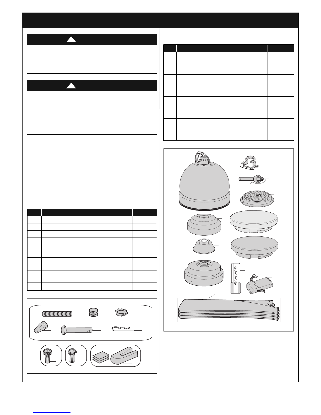
1.1
Open carton containing fan. Remove top half of styrofoam
unit. Remove parts and check to see that you have
received the following parts:
NOTE: If you are uncertain of part description, refer to
exploded view illustration.
PACKAGE CONTENTS
Part Description Quantity
A Fan Motor Assembly 1
B Hanger Bracket 1
C Hanger Ball/4.5” Downrod 1
D Ceiling Canopy 1
E Motor Coupling Cover 1
F Light Kit Adapter 1
G Fan Blade Assemblies 3
H LED Light Kit Assembly 1
I Acrylic Shade 1
J No-Light Plate 1
K Remote Control, SR401 1
L Receiver 1
HARDWARE CONTENTS
Part Description Quantity
1 Threaded Studs, #8-32 x 1-1/4” 2
2 Knurled Knobs, #8-32 2
3 Lockwashers, External Tooth, #8 2
4 Wire Connectors 5
5 Clevis Pin 1
6 Hairpin Clip 1
7 Pan Head Screws w/Lockwashers,
1/4-20 x 9/16” 10
8 Truss Head Screws w/Lockwashers,
6-32 x 3/8” (Spares) 2
9 Blade Balance Kit 1
NOTE: Place the parts from the loose parts bags in a
sm all c ontainer to keep them from bei ng lost.
If any parts are missing, call 1-800 -654-354 5
for replacement parts before proceeding.
emersonfans.com
Please contact 1-800-654-3545 for further assistance
3
ETL Model No.: CF590
1. Unpacking Instructions (Continued)
This Manual Is Designed to Make it as Easy as Possible for You to Assemble,
Install, Operate and Maintain Your Ceiling Fan
THIS FAN IS SUITABLE FOR WET LOCATIONS SUCH AS
PORCHES, PATIOS, AND DECKS.
Tools Needed for Assembly
One Phillips head screwdriver One stepladder
One 1/4” blade screwdriver One wire stripper
Materials
Wiring outlet box and box connectors must be of type
required by the local code. The minimum wire would be a
3-conductor (2-wire with ground) of following size:
Installed Wire Length Wire Size A.W.G.
Up to 50 ft. 14
50-100 ft. 12
2. Electrical Requirements
Your new ceiling fan will require a grounded electrical
supply line of 120 volts AC, 60 Hz, 15 amp circuit.
The outlet box must be securely anchored and capable of
withstanding a load of at least 50 pounds.
Your Emerson Ceiling Fan comes sup plied wit h a
RCFP Receiver and Fan Remote Control. This system
allows you to regulate your ceiling fan speed and light
control.
Th is Emerso n Ce iling Fan may be used with t he
fo llowing ac cessory (p urchased sep arately) :
SW605 Wall Control.
WARNING
Before assembling your ceiling fan, refer to section on
proper method of wiring your fan (page 15). If you feel
yo u do not have enou gh wir in g know ledge or
experience, h av e your fa n installed b y a licensed
electrician.
If your fan is to replace an existing ceiling light fixture, turn
electricity off at the main fuse box at this time and remove
the existing light fixture.
WARNING
!
!
WARNING
To reduce the risk of fire, electric shock, or personal
injury, mount fan to outlet box marked “Acceptable for
Fan Support of 22.7kg. (50 lbs.) or less”, and use
screws supplied with outlet box. Most outlet boxes
commonly used for support of light fixtures are not
acceptable for fan support and may need to be replac
ed. Consult a qualified electrician if in doubt.
WARNING
Turning off wall switch is not sufficient. To avoid
possible electrical shock, be sure electricity is turned
off at the main fuse box before wiring. All wiring must
be in accordance with National and Local codes and
th e ceiling fan must be pr operly grou nded as a
precaution against possible electrical shock.
ETL Model No.: CF590
!
!
To avoid fire or shock, follow all wiring instructions
carefully.
An y el ectrical wor k no t de scribed in the se
instructions should be done or approved by a licensed
electrician.
Pl ease ca ll Em erson t echnical support at
1- 800-654- 3545 if you have a ny que stions about
installation and operation of this ceiling fan.
4

3. Ceiling Fan Assembly
FAN MOTOR
ASSEMBLY
CARDBOARD
SHIPPING
SPACER
PLASTIC BAG
MOTOR HUB
6-32 x 3/8" TRUSS
HEAD SCREW
WITH
LOCKWASHER
ROTATE CLOCKWISE
LIGHT KIT
ADAPTER
MOTOR HUB
FAN MOTOR
ASSEMBLY
FAN BLADE ASSEMBLY
1/4-20 x 9/16" PAN HEAD
SCREW WITH LOCKWASHER
(3 per blade assembly)
MOTOR HUB
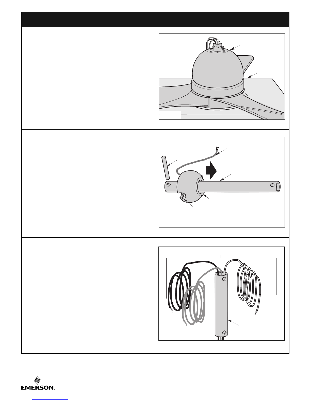
3.1
Remove fan motor assembly from styrofoam. Remove
cardboard shipping spacer and plastic bag.
Place fan motor assembly on styrofoam with the motor hub
positioned up (Figure 1).
3.2
Loosely attach one ceiling fan blade assembly to the motor
hu b of the fan motor ass embly using thr ee
1/4-20 x 9/16” Pan Head Screws with Lockwashers
(supplied in the parts bag) (Figure 2).
Figure 1
Repeat this procedure for the other two blade assemblies.
Securely tighten the nine 1/4-20 x 9/16” Pan Head Screws
with Lockwashers to the motor hub at this time.
WARNING
To reduce the risk of personal injury, do not bend the
blade assemblies when installing, balancing the blades
or cleaning the fan. Do not insert foreign objects in
between rotating fan blades.
3.3
Re move one of the thr ee 6-32 x 3/8” Tr uss Head
Screws with Lockwashers in the motor hub of the fan
mo tor a ssembly an d loo sen t he remaini ng two
6-32 x 3/8” T russ Head Screws with Loc kwasher s
positioned in the key hole slots (Figure 3). Retain the
screw for future use.
Position the Light Kit Adapter key hole slots onto the two
loosened screws.
Rotate the Light Kit Adapter clockwise to engage the two
screws.
Reinstall the previously removed screw.
Retighten the three screws to securely assemble the Light
Kit Adapter to the motor hub.
Spare 6-32 x 3/8” Truss Head Screws with Lockwasher in
the parts bag.
!
Figure 2
Figure 3
emersonfans.com
Please contact 1-800-654-3545 for further assistance
5
ETL Model No.: CF590
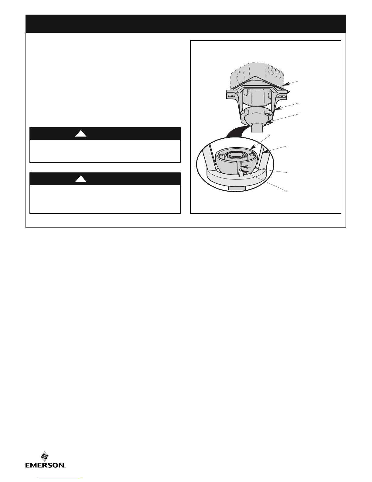
3. Ceiling Fan Assembly (Continued)
THREE 80" MOTOR LEADS
4.5" DOWNROD
PHILLIPS HEAD SET SCREW
(LOOSENED)
HANGER BALL
4.5" DOWNROD
PIN
GREEN GROUND WIRE
PARTIALLY ASSEMBLED
CEILING FAN
STYROFOAM
3.4
arefully turn the partially assembled ceiling fan right side
C
up and position the fan on the styrofoam in preparation for
final assembly (Figure 4).
3.5
Remove the hanger ball by loosening the Phillips head
setscrew in the hanger ball until the ball falls freely down
the 4.5” downrod (Figure 5).
Figure 4
Remove the pin from the 4.5” downrod, then remove the
hanger ball (Figure 5).
Retain the pin and hanger ball for reinstallation in
Step 3.11.
3.6
Separate, untwist and unkink the three 80” motor leads.
Route the three motor leads through the 4.5” downrod
(Figure 6).
Figure 5
ETL Model No.: CF590
Figure 6
6
MOTOR
COUPLING
4.5"
DOWNROD
LOOSEN
PHILLIPS HEAD
S
ETSCREWS (2)
3. Ceiling Fan Assembly (Continued)
HAIRPIN
CLIP
MOTOR
COUPLING
RETIGHTEN
PHILLIPS HEAD
SETSCREWS (2)
CLEVIS
PIN
HAIRPIN
CLIP
CLEVIS
PIN
GROMMET
COUPLING
COVER
DOWNROD
FAN MOTOR
HOUSING
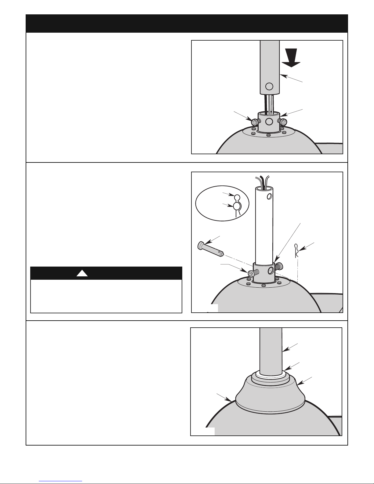
3.7
Loosen the two setscrews in the motor coupler for
installation of the downrod (Figure 7).
Seat the downrod in the motor coupler (Figure 7).
otate and align the downrod holes with all the holes in the
R
motor coupler (Figure 7).
3.8
Align the clevis pin holes in the downrod with the holes in
the motor coupler.
Figure 7
Install the clevis pin and secure with the hairpin clip
(Figure 8).
The clevis pin must go through the holes in the motor
coupler. It is critical that the clevis pin in the motor coupler
is properly installed and securely tightened.
Retighten the Phillips head setscrews to secure the
downrod to the motor (Figure 8).
WARNING
It is critical that the clevis pin and setscrews in the motor
coupler are properly installed and securely tightened.
Failure to verify that the pin and setscrews are properly
installed could result in the fan falling.
!
3.9
Make sure the grommet is properly installed in the
coupling cover, then slide the coupling cover on the
do wnrod until it rests on th e fan motor housing
(Figure 9).
Figure 8
7
Figure 9
emersonfans.com
Please contact 1-800-654-3545 for further assistance
ETL Model No.: CF590
3. Ceiling Fan Assembly (Continued)
6 TO 9
INCHES
HANGER BALL
WHITE WIRE
BLACK WIRE
1/2-INCH
BLUE WIRE
PIN
HANGER BALL
4.5" DOWNROD
PHILLIPS HEAD
SETSCREW
DOWNROD
CEILING
COVER
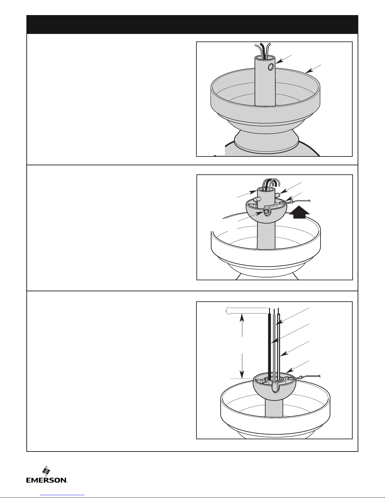
3.10
lace the ceiling cover over the downrod (Figure 10).
P
Be sure that the ceiling cover and the coupling cover are
oth oriented correctly (Figure 10).
b
3.11
Route the three 80” motor leads through the hanger ball
(Figure 11).
Reinstall the hanger ball on the downrod as follows:
Position the pin through the two holes in the downrod and
align the hanger ball so the pin is captured in the groove in
the top of the hanger ball (Figure 11).
Figure 10
Pull the hanger ball up tight against the pin and securely
tighten the Phillips head setscrew in the hanger ball
(Figure 11).
Loose setscrew could create fan wobble.
3.12
The fan comes with black, blue, and white leads that are
80-inches long.
Measure up approximately 6 to 9-inches above top of
hanger ball/4.5” downrod assembly (Figure 12).
Cut off excess leads and strip back insulation 1/2-inch from
end of leads.
Figure 11
ETL Model No.: CF590
Figure 12
8
FLOOR
C
EILING
AT
LEAST
7'
4. How to Hang Your Ceiling Fan
TWO SCREWS
SUPPLIED WITH
OUTLET BOX
HANGER BRACKET
ANTI-ROTATION TAB
OUTLET BOX
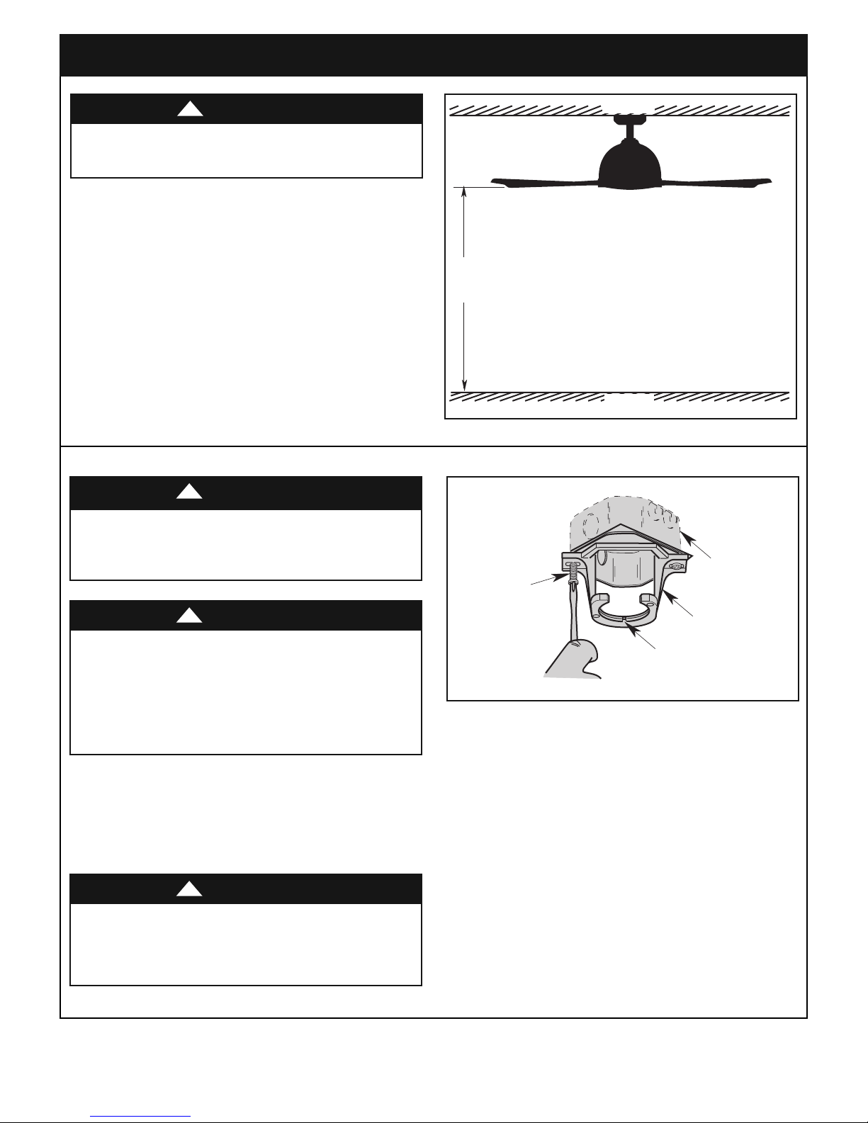
WARNING
The fan must be hung with at least 7' of clearance from
floor to blades (Figure 13).
WARNING
!
!
Figure 13
The outlet box and joist must be securely mounted and
capable of supporting at least 50 lbs. Use only a U.L.
outlet box listed as “Acceptable for Fan Support of 22.7
kg. (50 lbs.) or less”.
WARNING
To reduce the risk of fire, electric shock, or personal
injury, mount fan to outlet box marked “Acceptable for
Fan Support of 22.7 kg. (50 lbs.) or less”, and use screws
supplied with outlet box. Most outlet boxes commonly
used for support of light fixtures are not acceptable for
fan support and may need to be replaced. Consult a
qualified electrician if in doubt.
!
4.1
Securely attach the hanger bracket to the outlet box using
the two screws supplied with the outlet box. (Figure 14).
WARNING
Hanger bracket must seat firmly against outlet box. If the
outlet box is recessed, remove wall board until bracket
contacts box. If bracket and/or outlet box are not securely
attached, the fan could wobble or fall.
!
Figure 14
emersonfans.com
9
Please contact 1-800-654-3545 for further assistance
ETL Model No.: CF590
4. How to Hang Your Ceiling Fan (Continued)
OUTLET
BOX
HANGER
BRACKET
HANGER BALL/
DOWNROD
ASSEMBLY
NOTE: CEILING COVER, SUPPLY WIRES AND FAN WIRES
OMITTED FOR CLARITY.
HANGER BRACKET
HANGER BALL
HANGER BALL
GROOVE
ANTI-ROTATION
TAB
4.2
Carefully lift the partially assembled ceiling fan and seat
the hanger ball/downrod assembly on the hanger
br acket that was just attached to the outlet box
(Figure 15).
Be sure the groove in the ball is engaged with the antirotation tab on the hanger bracket (Figure 15).
NO TE: Be very care ful not to bend the bla de
assemblies while hanging the partially assembled
ceiling fan.
WARNING
Failure to seat tab in groove could cause damage to
electrical wires and possible shock or fire hazard.
WARNING
To avoid possible fire or shock, do not pinch wires
between the hanger ball/downrod assembly and hanger
bracket.
!
!
Figure 15
ETL Model No.: CF590
10
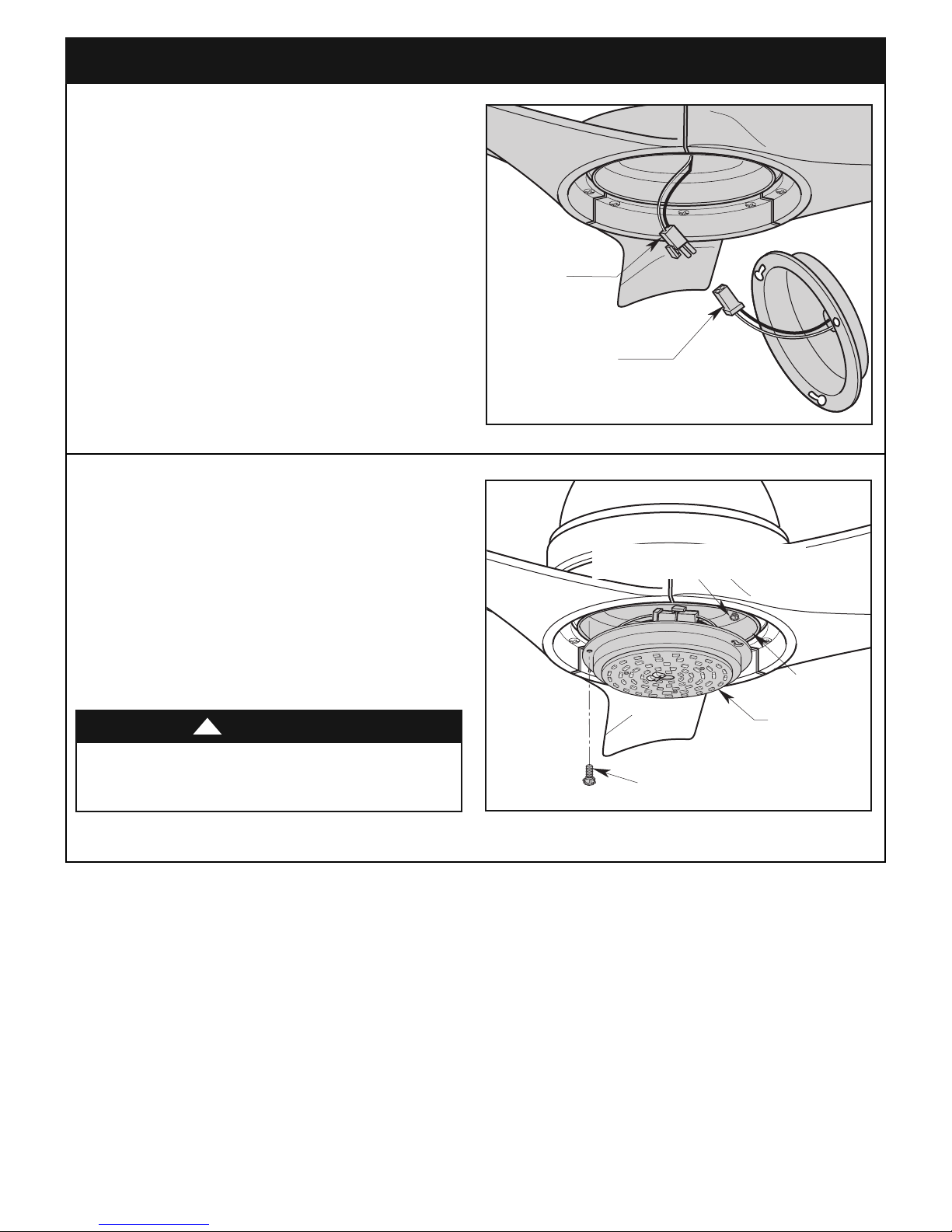
5. Light Kit Assembly
LIGHT KIT ASSEMBLY
2-PIN CONNECTOR
FAN MOTOR
ASSEMBLY
2-PIN CONNECTOR
H
LIGHT KIT
ASSEMBLY
LIGHT KIT
ADAPTER
REMOVE ONE 6-32 x 3/8" TRUSS HEAD
SCREW WITH LOCKWASHER
LOOS EN THE TWO 6-32 x 3/8" TRUSS HEAD
SCREWS WITH LOCKWASHERS
OTE: If installing Ceiling Fan without the Light Kit
N
Assembly, Skip to Section 6. Optional Installation of
No-Light Plate Assembly, Step 6.4.
5.1
Engage the fan motor 2-pin wire connector into the
2- pin w ire connector o f the Light Kit A ssembly
(Figure 16).
The connection is complete when you hear a soft click.
5.2
Remove one of the three 6-32 x 3/8” Truss Head Screws
with Lockwashers in the Light Kit Adapter and loosen the
remaining two screws (Figure 17). Retain the screw and
lockwasher for future use.
Figure 16
Carefully tuck all the wires into the Light Kit Adapter prior to
installing the Light Kit Assembly (Figure 17).
Position the Light Kit Assembly key hole slots onto the two
lo osened 6-32 x 3/8” Pan Head Scre ws wi th
Lockwashers.
WARNING
To avoid possible fire or shock, do not pinch wires
between the Light Kit Assembly and the Light Kit
Adapter.
!
Figure 17
11
emersonfans.com
Please contact 1-800-654-3545 for further assistance
ETL Model No.: CF590
 Loading...