

Emerson Varec 5000X3, Varec 5000X2, Varec 5000X1, Varec 5000X6, Varec 5010X1 Installation, Operation And Maintanance Instructions
...
VAREC SERIES 5000/5010 FLAME ARRESTERS
InstructIon, operatIon and maIntenance manual
Before installation these instructions must be fully read and understood
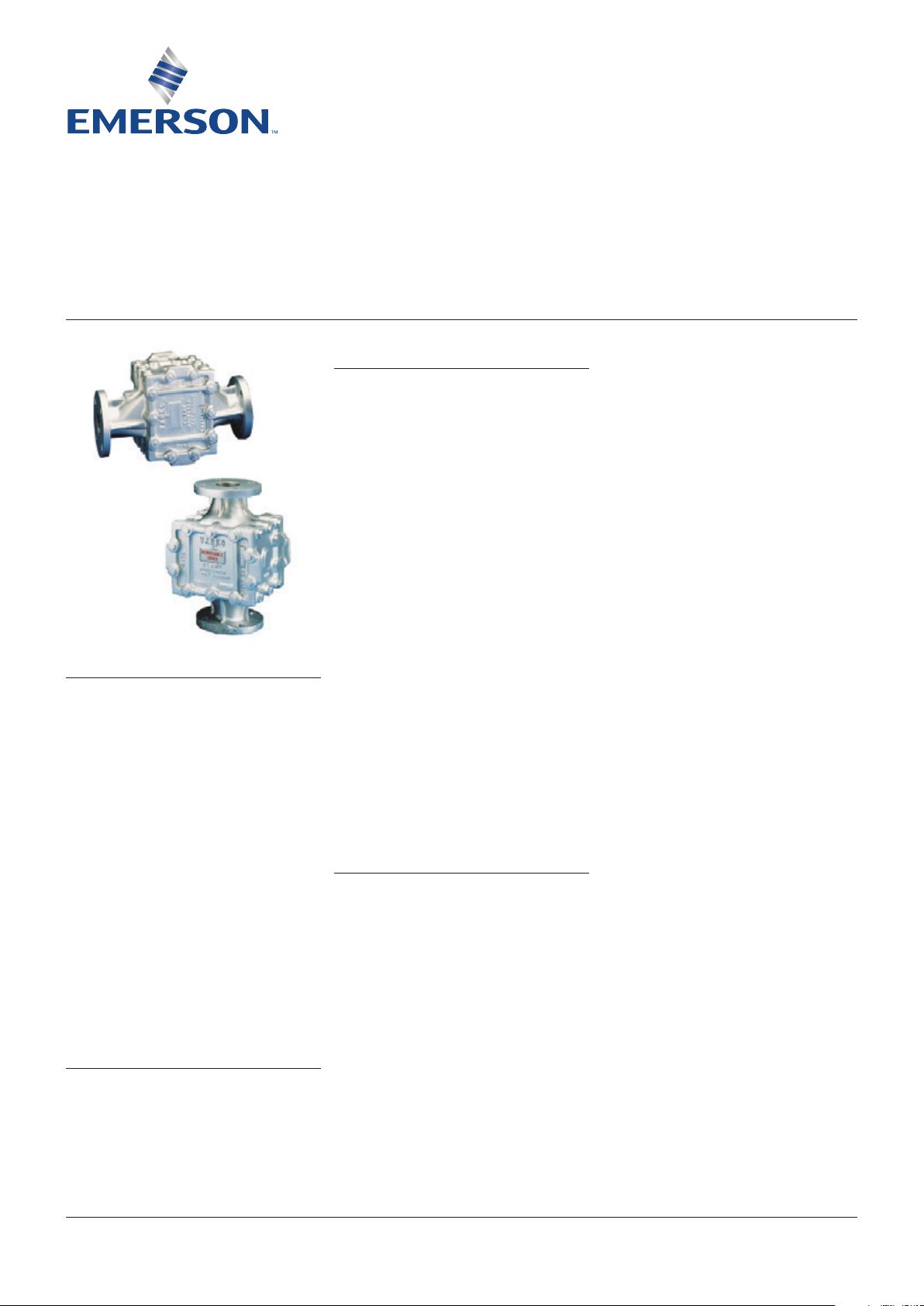
5010 series horizontal
5000 series vertical
DISCLAIMER OF WARRANTIES
The contract between the seller and the buyer
states the entire obligation of the seller. The
contents of this instruction manual shall not
become part of or modify any prior or existing
agreement, commitment or relationship
between the seller and buyer. There are no
express or implied warranties set out in this
instruction manual. The only warranties that
apply are those in the existing contract between
the seller and buyer.
The Varec 5000/5010 Series flame arresters
have not been tested by Varec under all
possible operational conditions and Varec
does not have all the data relative to your
application. The information in this instruction
manual is not all inclusive and does not and
cannot take into account all unique situations.
Consequently, you should review this product
literature in view of your application. If you have
any further questions, please contact Varec for
assistance.
SAFETY PRECAUTIONS
Read and understand this instruction manual
before installing, operating or performing
maintenance on varec 5000/5010 series flame
arresters. Follow all precautions and warnings
noted herein when installing, operating or
performing maintenance on this equipment.
WARNING
Flame arresters should be installed upstream and
not more than 15 feet from the ignition source for
use in accordance with UL approval.
Flame arresters must be isolated from the gas
piping before performing maintenance. All gas
must be blocked and pressure safely vented.
Flame arresters are not capable of stopping
a flame front in mixtures of air with hydrogen,
acetylene, ethylene oxide, or carbon disulfide.
Safety precaution definitions:
CAUTION
Damage to equipment may result if this precaution
is disregarded.
WARNING
Direct injury to personnel or damage to equipment
which can cause injury to personnel may result if
this precaution is not followed.
GENERAL
The Varec Model 5000/5010 Series flame
arresters are designed to stop the propagation
of flame from external sources. They are used
on storage tank roofs, digester covers and in
waste gas piping systems. These units are
installed where fire protection is required in
combination with pressure relief or shut-off
valves in vapor balancing, recovery or open vent
piping systems.
NOTE
Varec flame arresters bearing UL approval are tested
for use on oil storage tanks, installed not more than
15 feet from the open end of the vent pipe (reference
UL 525). These test conditions may not represent the
actual service conditions or piping system design. API
publication 2028 states that the arresters should be
independently tested under actual service conditions
before installation.
LIMITATIONS OF SELLER'S LIABILITY
If it is determined that this instruction manual
created some new warranties, Varec’s liability
shall be limited to repair or replacement under
the standard warranty clause. In no case
shall Varec’s liability exceed that stated as
Limitations of Remedy in the contract between
Varec and our customer.
Emerson.com/FinalControl
WARNING
Flame arresters are not capable of stopping
a flame front in mixtures of air with hydrogen,
acetylene, ethylene oxide, or carbon disulfide.
Flame arrester should be installed upstream
of and not more than 15 feet from the ignition
source for use in accordance with UL aproval.
Engineering Doc. #33-07765 Rev. G
© 2017 Emerson. All Rights Reserved. VCIOM-03772-EN 18/02

VAREC SERIES 5000/5010 FLAME ARRESTER
InstructIon, operatIon and maIntenance manual
CONSTRUCTION
WARNING
The standard unit is constructed of a heavy
cast housing containing a removable multiplate
bank assembly with aluminum extensible
frame. A fixed 316 S.S. frame is also available.
Working pressure rating is 10 Psig (69.0 kPa).
For material selection see Tables 4 and 6.
In all cases where the ratio of upper limit/lower
limit exceeds 10, the use of flame arresters is
not recommended. Also, the presence of any O
is dangerous because of the lack of homogeneity
which is possible in gas mixtures. Any surplus of
oxygen provides the potential for rapid explosion.
2
PRACTICAL LIMITATIONS
While flame arresters decrease the possibility
of flame propagation in a system, certain
variables must be evaluated to ensure safety.
The relative fire hazard of flammable mixtures
can be judged by the upper and lower explosive
limits. These limits are expressed as percent by
volume of the gas or vapor in air. The explosive
range is that span of concentrations lying
between the lower and upper limits. The upper
limit is the point at which the mixture is too rich
to burn, i.e., contains too little oxygen to support
combustion. The broader the explosive range,
the easier it is to create an air-gas explosive
mixture. Conversely, when the explosive range
is narrow, the chance of developing a hazardous
air-gas mixture decreases.
Table 1 gives the approximate limits of
flammability of some single gases, vapors
and industrial mixtures in air at common
temperatures and at atmospheric pressure.
OPERATION
Flame arresters do not prevent ignition of
flammable mixtures, but do prevent the
propagation of a flame. The Varec 5000/5010
Series flame arresters stop flame propagation
by absorbing and dissipating heat through
the surface area of the bank sheets. Heat
is absorbed as ignited gas attempts to pass
through the small passages within the bank
assembly. This action lowers the temperature
of the gas below its ignition point and quenches
the flame.
TABLE 1 - FLAMMABILITY LIMIT OF GASES AND VAPOR
Limits in air pressure
Product
Acetyldehyde 4.1 55 Ethyl-Alcohol 4.3 19 Methyl-Alcohol 7.3 36
Acetone 3 11 Ethyl-Bromide 6.7 11.3 Methyl-Chloride 10.7 17.4
Acetylene 2.5 81 Ehtyl-Chloride 3.8 15.4 Methyl-Ethyl-Ketone 1.8 10
Ammonia 15 28 Ethyl-Ether 1.9 48 Methyl-Formate 5.9 20
Benzene 1.4 7.1 Ethyl-Formate 2.7 13.5 Methyl-Proply-Ketone 1.5 8
Benzine 1.1 Ethylene 3.1 32 Natural gas 3.8 17
Blast furnace gas 35 74 Furfural 2.1 Noriane 0.8
Butadiene 2 11.5 Gasoline 1.4 7.6 Octane 1
Butane 1.9 8.5 Hexane 1.2 7.5 Pentane 1.5 7.8
Butylene 2 9.6 Heptane 1.2 6.7 Propane 2.1 9.5
Carbon Disulphide 1.25 44 Hydrocyanic acid 6 41 Propyl-Alcohol 2.1 13.5
Carbon Monoxide 12.5 74 Hydrogen 4 75 Propylene 2.4 10.3
Cyclohexane 1.3 8 Hydrogen-Sulhide 4.3 5 Pyridine 1.8 12.4
Cyclopropane 2.4 10.4 Isobutane 1.8 8.4 Styrene 1.1 6.1
Decane 0.8 5.4 Isopentane 1.4 7.6 Toluene 1.4 6.7
Ethane 3 12.5 Isopropyl-Alcohol 2 12 Water gas 7 72
Ethyl-Acentate 2.5 9 Methane 5.3 14 Xylene 1 6
Reference: Bureau of Mines bulletin 503, Limits of flammability of gases and vapors, 1952
Lower Higher Lower Higher Lower Higher
Product
Limits in air pressure
Limits in air percent
Product
2

VAREC SERIES 5000/5010 FLAME ARRESTER
InstructIon, operatIon and maIntenance manual
INSTALLATION
The 5000 Series flame arrester (ref. Figure 2)
is designed for vertical application in pipe lines
and on tank or digester roofs. The 5010 Series
flame arrester (ref. Figure 3) is designed for
horizontal positioning in pipelines, however, it
may be in either direction.
The cover, roof or piping system must have
the appropriate flange(s) installed for mating
with the flame arrester. Flame arrester with
aluminum housings should be mated with an
ANSI Class 125 F.F. flange. The 316 stainless
steel housing should be mated with an ANSI
Class 150 R.F. flange. The arrester must be
located with clearance allowed for removal of
the bank assembly.
The flange of vertical mounting must be plumb
and level to ensure proper operation of the
pressure relief valve (when used in combination
with the flame arrester).
The flange for horizontal mounting must be
oriented to ensure that arrester drain hole will
be at the extreme bottom (6 o’clock) position.
1. Remove the flame arrester from the
shipping container or pallet.
2. Remove flange protectors. Inspect for and
remove any packing or other loose material
in the inlet/outlet chambers of the housing.
3. Remove cover and extract bank assembly.
Inspect for shipping debris or damage and
correct as required. Insert bank and replace
cover. Tighten cap screws uniformly.
WARNING
The aluminum bank assembly weighs from
10 to 80 pounds and the 316 S.S. assembly is
substantially heavier. Use the appropriate tools
and equipment when handling these units to avoid
injury.
4. Place the appropriate full face flange gasket
(by others) on the flange.
CAUTION
If it is necessary to mate an ANSI Class 125 F.F.
flange with an ANSI Class 150 R.F. flange, use
the proper spacer to convert the raised face to a
flat face.
5. Place the arrester on the flange, and
position the unit so that the bank assembly
can be readily extracted for inspection and
maintenance.
NOTE
When installing the Model 5010 in a horizontal
position, check the drain hole to see that it is
functional. Install the appropriate drain piping along
with a Varec Drip trap or an isolation valve.
6. Install mounting hardware and tighten
uniformly.
The flame arrester is now installed and ready
for use.
MAINTENANCE
Maintenance is the most important factor
in the operation of the flame arrester. The
bank sheets must be kept clean to prevent a
decrease in gas flow through the system and
loss of heat absorbing efficiency.
WARNING
Failure to properly maintain the unit could result
in reduction of safety and impairment of system
operation.
A regular inspection program is important. The
frequency of inspection is determined by the
application. Consideration should be given to
the amount and nature of water or solids in the
gas and the corrosivity of the process stream.
Generally, the first inspection should be made
30 days after commissioning. Inspections
should continue on a 30 day schedule unless
excessive deposits or accumulation of foreign
matter are found. If so, the frequency of
inspections should be increased. Adjust
inspection frequency to maintain free and
unrestricted flow through the arrester.
WARNING
Flame arrester must be isolated from the gas
piping before removing cover plate. All gas
must be blocked and pressure safely vented.
Ensure that arrester is cool after a fire, or wear
appropriate protective clothing.
1. Remove cover cap screws and cover plate.
Pull out bank assembly by pulling on bank
handle. If desired, the bank assembly may
be removed from the housing.
WARNING
The aluminum bank assembly weighs from
10 to 80 pounds and the 316 S.S. assembly is
substantially heavier. Use the appropriate tools
and equipment when handling these units to avoid
injury.
a. Extend the aluminum frame to its full open
position. Both sides of each grid sheet may
be inspected and cleaned without removal
from the frame.
b. The 316 S.S. frame is non-extensible and
must be disassembled to access the bank
sheets.
2. Check for corrosion, bent, warped or
otherwise damaged sheets that could cause
an opening for a direct flame path. Replace
with a new bank assembly if necessary.
3. Bank assembly cleaning procedure is
based on the type of residue to be removed.
Determine if residue type is Group I, II, or
III. Follow the cleaning procedures for the
selected group.
WARNING
Use all volatile and flammable solvents carefully
to avoid ignition or prolonged breathing. Use
protective clothing and gloves when using acid to
avoid burns from contact with skin.
3
 Loading...