

Page 1

VANESSA SERIES 30,000
InstallatIon and MaIntenance InstructIons
Installation and Maintenance Instructions Vanessa Series 30,000 - Basic configuration
body style double flanged, wafer, lug and buttweld
All actuated valves must be securely
palleted or crated with particular attention,
in order to ensure that parts of actuator
(especially pneumatic piping or accessories)
do not extend beyond the skid/crate.
4 The type of packing must be defined in the
customer’s order and will be appropriate
to ensure safe transportation to final
destination and eventual conservation
before installation.
1.2 Handling requirements
Applicable product range
• Series 30,000 Basic configuration, double
flanged body style, which can be installed
between two flanges or stud-bolted to either
flange.
• Series 30,000 Basic configuration, lug-single
flange body style, which must be bolted to
either flange.
• Series 30,000 Basic configuration, wafer body
style, which can be installed between two
flanges.
• Series 30,000 Basic configuration, buttweld
ends, which must be welded to the line.
SECTION 1 - VALVE STORAGE
1.1 Preparation and preservation for shipment
All valves are properly packed in order
to protect the parts that are subject to
deterioration during transportation and storage
on site. In particular, the following precautions
should be taken:
1 The valves must be packed with the disc
in the closed position. The flange sealing
surfaces (raised faces) of the valves will be
protected with suitable protective grease.
The end faces of the valve must be protected
with plastic or wooden discs fixed with
straps.
2 Bare shaft valves: the ends of the shaft must
be protected with plastic tubes.
3 Valves with actuators: in case of “fail
open” pneumatic - hydraulic actuators
with manual override, the manual override
shall be used to manually close the valves
and to lock them in position. If there is no
manual override, cut outs are made in the
flange protectors for the disc, and the disc is
securely protected.
A - Packed valves
Crates: Lifting and handling of the packed
valves in crates will be carried out
by a fork lift truck, by means of the
appropriate fork hitches.
Cases: The lifting of packed valves in cases will
be carried out in the lifting points and
in the center of gravity position which
have been marked. The transportation
of all packed material must be carried
out safely and following the local safety
regulations.
B - Unpacked valves
1 The lifting and the handling of these valves
has to be carried out by using appropriate
means and by respecting the carrying limits.
The handling must be carried out on pallets,
protecting the machined surfaces to avoid
any damage.
2 With large dimension valves, the sling and
the hooking of the load must be carried out
by using the appropriate tools (brackets,
hook, fasteners, ropes) and load balancing
tools in order to prevent them from falling
or moving during the lifting and handling.
Emerson.com/FinalControl
© 2017 Emerson. All Rights Reserved.
VCIOM-00006-EN 18/04
Page 2

VANESSA SERIES 30,000
InstallatIon and MaIntenance InstructIons
1.3 Storage and preservation before
installation
In case the valves have to be stored before
installation, the storage has to be carried out
in a controlled way, and has to be performed in
accordance to the following criteria:
1 The valves have to be stocked in a closed,
clean and dry storage room.
2 The disc must be in the closed position,
and the end faces must be protected with
plastic or wooden discs fixed with straps. If
possible, keep the original protection.
3 Periodical checks have to be carried out
in the storage area to verify that the above
mentioned conditions are maintained.
NOTE
Storage in an open area for a limited period can be
considered only in case the valves have appropriate
packing (packed in cases lined with tarred paper, and
contents well protected with barrier sacks).
CAUTION
For valve handling and/or lifting, the lifting
equipment (fasteners, hooks, etc.) must be sized and
selected while taking into account the valve weight
indicated in the packing list and/or delivery note.
Lifting and handling must be made only by
qualified personnel.
LIFTING AND HANDLING OF VALVES INSTALLED IN HORIZONTAL PIPELINE
FIGURE NO. 1A
Fasteners must be protected by plastic covers in
sharp corner areas.
Caution must be taken during the handling to
avoid that this equipment passes over the workers
or over any other place where a possible fall
could cause damage. In any case, the local safety
regulations must be respected.
NOTE
Solutions A and C are applicable when the protrusion
of the bottom hub from the flange or body is sufficient
to position securely the lifting strap.
Solutions B and D are applicable when the protrusion
of the bottom hub from the flanges is NOT sufficient to
position securely the lifting strap.
In presence of solution B, insert a stud bolt and fix it
securely with nuts as indicated in the drawing detail.
In presence of solution D, insert a lifting eyelet in the
flange threaded holes close to the bottom hub and fix
it securely as indicated in the drawing detail.
LIFTING AND HANDLING OF VALVES INSTALLED IN VERTICAL PIPELINE
FIGURE NO. 1B
2
Page 3

VANESSA SERIES 30,000
InstallatIon and MaIntenance InstructIons
SECTION 2 - INSTALLATION
2.1 Valve inspection
1 Carefully remove the valve from the
shipping package (box or pallet) avoiding any
damage to the valve or, in case of automated
valves, to the electric or pneumatic/
hydraulic actuator or instrumentation.
2
The valves are shipped with the ends
protected with caps and a thin layer of
protective grease. Before installing the valve,
remove the caps and clean carefully, then
de-grease both surfaces with a solvent.
Clean the inside of the valve using an air line.
Ensure that there are no solid objects such as
pieces of wood, plastic or packing materials
within the valve or on the valve seat.
3 Inspect the seal ring to ensure that it
was not damaged during handling. This
is especially important in case of valves
shipped with the disc in the open position
and with “fail-open” actuators.
4 Confirm that the materials of construction
listed on the valve nameplate are
appropriate for the service intended and are
as specified.
5 Ensure that the packing gland adjusting
nuts against the packing gland flange
cannot be rotated by hand.
2.2 Valve installation
Vanessa recommends that the optimum valve
installation is with the shaft in the horizontal
plane, after which it is preferable to have the
shaft at an angle so as to minimize any problem
associated with solid particles present in the
fluid that otherwise could deposit in the lower
bearing area.
NOTE
The Vanessa valve is designed to withstand design
differential pressure in both directions.
Isolating applications
The valve operating torque affects the sealing
performances. Vanessa attached the indication plate
P (figure 2) on the upstream flange as a reference for
the direction of the installation.
The best sealing performance, also for bi-directional
service, will be maintained when pressure acts on the
shaft side of the valve, which is recommended when
the service tightness requirements are more stringent
in one specific direction.
Control applications (uni-directional, where perfect
sealing is not required)
The plate could be fixed on either flange indicating
the preferred direction. Please respect the direction
of installation indicated on the relevant flange. The
selection of the actuator has been made for that
specific direction of installation.
Unless otherwise recommended by Vanessa,
the valve should be installed with the disc in
the closed position to ensure that the seal ring
in the disc is not damaged during installation.
Particular care should be taken with those
valves equipped with ‘fail-open’ actuators.
For operating temperatures above 200°C
(392°F) thermal insulation of the valve body is
recommended.
If the valve has threaded tapped holes in
the hub areas, Vanessa recommends to use
hexagonal head bolts or shorter studs to
connect the valve in this zone. The depth of the
tapped holes in the bodies of all Series 30,000
valves is specified in the technical literature.
Failure to use correct bolts/studs may result in
damage to the valve.
If the valve has welded ends, perfectly clean
and degrease the ends to be welded (of both
valve and pipe), using a cloth with acetone
or similar product. Insert correctly the valve
between the edges of the pipe to be welded,
taking care of the plate that indicates the
preferential side for sealing. Carry out an initial
accurate spot welding verifying the perfect
alignment of the edge and axis of the valve.
Carry out the welding of the edge proceeding
in alternate way on both sides to reduce
the tensions introduced by the welding. It is
important to respect the interpass temperature
which must not go above 150°C (302°F).
Handling and lifting of the valves during
installation MUST be performed following the
same criteria and instructions described in
previous points “1.2 Handling requirements”
and “1.3 Storage and preservation before
Installation”.
IMPORTANT
The valve trim is designed to withstand and to seal
against the design differential pressure marked
on the valve nameplate which data are supplied
together with the present document.
Since it is impossible to maintain complete
control on the external input forces to the trim
coming from gear/actuator, the valve trim shall
not be used as a final protective mean against
the hazard caused by the closed valve upstream
pressure.
IMPORTANT
It is recommended to perform piping flushing
before installation of valve.
If this is not possible, the valves must be set with
the disc in full open position before starting with
flushing.
CAUTIONS
When the pipe is lined, be careful that the disc
does not come into contact with the lining during
its stroke, especially in lug and wafer body styles.
This verification is very important to avoid any
damage to the valve.
FIGURE 2
3
Page 4

VANESSA SERIES 30,000
InstallatIon and MaIntenance InstructIons
2.3 Valve verification
1 Tighten the packing just enough to prevent
stem leakage. Over-tightening will decrease
packing life and increase operating torque.
2 Check the operation of the valve by stroking
it to “full open” and “full close”. To verify the
valve orientation, the disc position indicator
mark on the shaft (during the normal open
to close cycle) should rotate clockwise from
a position in line with the pipe (see figure3a)
to a position parallel to the pipe flanges
(seefigure 3b).
IMPORTANT
If piping system is pressurized with water for
testing, and in case the piping system has been
shut down after testing for a long time, the
following recommendations should be adopted:
a. Use corrosion inhibitor with water to
pressurize the piping system.
b. After testing, the piping system should be
depressurized and the test water completely
drained.
c. After testing, valves must be maneuvered
through a complete opening/closing cycle and
disc left in half-open position. Apply a film of
protective oil in the packing area by means of a
paintbrush. The protective oil must fill the area
between shaft and packing bushing.
Clockwise to close
Disc in open position
FIGURE NO. 3A
Disc in closed position
Disc position
indicator mark
Disc - shaft key and position indicator mark plane
Shaft key
Disc position indicator mark
Clockwise to close
Shaft key
FIGURE NO. 3B
Disc - shaft key and position indicator mark plane
4
Page 5

VANESSA SERIES 30,000
InstallatIon and MaIntenance InstructIons
2.4 TROUBLESHOOTING GUIDE
Symptom Possible cause Resolution
Valve won’t rotate 1. Packing is too tight 1. Loosen gland nuts
2. Actuator has failed 2. Replace or repair
3. Valve packed with debris 3. Flush or clean valve to remove debris
4. Stem key has sheared 4. Determine cause of shearing and correctly replace stem key
5. Fluid solidification between bearings and shaft 5. Flush bearings by flushing holes (if present)
Stem packing leaking 1. Gland flange nuts too loose 1. Tighten gland flange nuts
2. Packing damaged 2. Replace packing - see Paragraph 3.1
Bottom flange gasket leaking 1. Bottom flange bolting loose 1. Tighten bottom flange bolting
2. Spiral wound gasket damage 2. Replace gasket - see Paragraph 3.3
Valve leaking 1. Valve not fully closed 1. Close valve
2. Debris trapped in valve 2. Cycle and flush (with valve open) to remove debris
3. Actuator mechanical stops improperly set 3 Remove the stop for closure and reset properly
4. Seal ring damaged 4. Replace seal ring - see Paragraph 3.2
Jerky operation 1. Packing is too tight 1. Loosen gland nuts, cycle valve, retighten
2. Air supply inadequate 2. Increase air supply pressure and/or volume
3. Actuator/stem adapter misaligned 3. Remove actuator mounting and realign
5
Page 6

VANESSA SERIES 30,000
InstallatIon and MaIntenance InstructIons
SECTION 3 - MAINTENANCE
The Vanessa Series 30,000 has been designed
to require a minimum of maintenance.
WARNING
Depressurize the line before starting any
maintenance. Failure to do so may cause serious
personal injury and/or equipment damage.
3.1 Packing maintenance
If shaft leakage is observed through the
packing, tighten the gland nuts slowly and
evenly until the leakage stops.
CAUTION
Do not over-tighten packing gland nuts. Overtightening will increase the torque required to
operate the valve.
When tightening the gland nut, use half-turn
increments until leakage has stopped.
Please refer to the figure no. 4.
To replace the packing proceed as follows:
1 Remove the gear/actuator and relevant
connecting keys (4f). Please note the
actuator position relative to the valve
position for reassembly of gear/actuator
later.
2 Remove gland nuts (5d). If present, remove
bellevilIe springs (5n), taking care of noting
their assembly configuration to reassemble
them correctly (point 7).
3 Remove packing gland flange (5f), anti blow-
out ring if present (5g), and gland bushing
(5c).
4 Remove packing (5a). If valve is with packing
flush option, remove lantern ring also (5h).
5 Carefully clean packing cavity and shaft (4a).
6 Apply a thin film of lubricant on each new
packing ring (5a) surfaces (lubricant should
be in accordance with Table IV). Insert new
packing rings, paying attention to insert the
two braided rings at the bottom and top of
the entire packing. If valve is with packing
flush option, insert the lantern ring (5h) in
the same sequence as previously removed
(or as indicated in figure 4). If the packing
rings are of the split variety, install with
splits staggered at 180° from each other.
7 Reassemble gland bushing (5c), anti blow-
out ring if present (5g), and gland flange
(5f). If present, assemble the belleville
springs (5n), following the assembly
configuration noted in the previous point 2,
then assemble by hand the gland nuts (5d)
without tightening (after applying a thin film
of lubricant on the threads of the stud bolts,
in accordance with Table IV).
8
Reassemble keys (4f) on the upper stem end.
9 Reassemble gear/actuator and close the
valve.
CAUTION
Do not force actuator on the stem! This should be
a free moving fit.
10 Tighten gland nuts (5d) in accordance to
Table I (Torque values for gland nuts).
11 Cycle the valve.
12 Pressurize again the line.
13
If a leakage is detected, tighten the gland nuts
slowly and evenly until the leakage stops.
FIGURE NO. 4
6
Page 7
VANESSA SERIES 30,000
InstallatIon and MaIntenance InstructIons
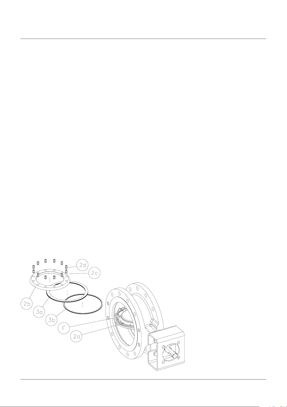
3.2 Sealing elements maintenance
To replace the sealing elements proceed as
follows (please refer to figure no. 5):
WARNING
Depressurize the line before starting any
maintenance. Failure to do so may cause
seriouspersonal injury and/or damage to the valve.
1 Remove the valve with the disc in the closed
position from line. Clean the valve according
to proper cleaning procedure as outlined by
the plant or according to a recommended
procedure.
2 Open the valve a few degrees.
3 Loosen the seal retainer ring screws (2c).
4 Open valve to full open position.
NOTE
In small size valves it may be easier to unbolt the
actuator and rotate the disc beyond the full-open
position to provide more space to work with components.
5 Carefully remove the retainer ring screws
(2c) with security washers (2d), then remove
the seal retaining ring (2b).
6 Remove seal ring (3a) and spiral wound
gasket (3b).
7 Inspect the body seat. Clean it, if necessary,
with fine abrasive cloth (No. 600 or finer),
after having cleaned it perfectly with solvent.
8 Inspect and clean the disc seal ring area
and spiral wound gasket groove. No foreign
particles must be present before spiral
wound gasket and seal ring assembly.
9 Apply a thin film of lubricant on the surface
area of the disc (2a) where seal ring (3a)
and spiral wound gasket (3b) will be located
(lubricant should be in accordance with
Table IV).
CAUTION
Apply only a thin film of lubricant where indicated.
Failure to do so will hinder the assembly and may
cause damage to the valve.
10 Assemble the new spiral wound gasket
(3b) in the disc groove, without forcing and
taking care not to damage it.
11
Replace seal ring (3a) on the disc through the
shaft side of the body. To properly locate the
seal ring, there are two different solutions:
• solution 1 - ref. to figure no. 6a: align the
internal slot of the seal ring (3a) to the
reference pin (F).
• solution 2 - ref. to figure no. 6b: align the
reference mark (C) on the seal ring (3a)
with the relevant reference mark (D) on
the disc.
12 Assemble the seal retainer ring (2b). There
are two different solutions as per previous
point 11:
• solution 1 - ref. to figure no. 6a: make
sure that the slot on the edge of the seal
retainer ring(B) is in correspondence with
reference pin (F).
• solution 2 - ref. to figure no. 6b: ensure to
locate the hole (E) of the seal retainer ring
with the relevant marks on the disc (D)
and seal ring (C).
13 Hand tighten all the fastening screws
(2c), with relevant lock washers (2d) after
applying Loctite
®
270 or equivalent on the
bottom side of the threads (they have to
be perfectly cleaned with solvent before
applying Loctite
®
). Then, verify that the seal
ring can be moved freely by hand without
rotating it.
14 Apply a thin film of lubricant to the body seat
and to the external edge (sealing conical
surface) of the seal ring (3a). Lubricant
should be in accordance with Table IV.
15 Seat and unseat the valve twice.
16 Keep the valve in the closed position without
applying torque. Tighten at least two
retaining screws (2c) to avoid the seal ring
moving from the position found.
FIGURE NO. 5
7
Page 8

VANESSA SERIES 30,000
InstallatIon and MaIntenance InstructIons
17 Open the disc a few degrees and tighten,
using a torque wrench, all screws (2c).
Use a torque value from Table III for valves
according to solution 1 (ref. to figure no. 6a).
Use instead a torque value from Table II for
valves according to solution 2 (ref. to figure
no. 6b).
It is recommended to use the crossover
method to tighten all retaining screws.
IMPORTANT
• Solution 1 - ref. to figure no. 6a:
The seal ring is supplied with an index marking (A).
After the complete assembling, verify that the
index marking (A) can be seen in the slot (B) of the
seal retainer flange.
Slot (B) and marking (A) have to be perfectly
aligned.
If not visible or not aligned, loosen the retaining
screws, re-align the index marking and start
again the procedure from point 12.
• Solution 2 - ref. to figure no. 6b:
The seal ring and the disc are completed with two
reference markings, (C) and (D).
After the complete assembling, verify that both
markings can be seen through the hole (E) of the
seal retainer flange. The two markings have to be
perfectly aligned.
If not visible or not aligned, loose the retaining
screws, re-align the index markings and start
again the procedure from point 12.
3.3. Bottom flange gasket maintenance
If necessary to replace the bottom spiral wound
gasket, proceed as follows (see fig. no. 7):
1 Remove the bottom flange (6a).
2 Remove the spiral wound gasket (6c).
3 Inspect and clean the groove of the spiral
wound gasket in the body and in the bottom
flange.
4 Apply a thin film of lubricant on the bottom
spiral wound gasket (6c), then insert it
on the bottom flange (6a), centering and
positioning all on the body bore (lubricant
should be in accordance with Table IV).
Rotate the bottom flange to accommodate
the correct position and center the holes
with the threaded holes on the body.
5 Apply a thin film of lubricant on the threads
of the screws (6b), then introduce and
tighten them using a torque value from
Table III (lubricant should be in accordance
with Table IV).
FIGURE NO. 6A
FIGURE NO. 7
FIGURE NO. 6B
8
Page 9
VANESSA SERIES 30,000
InstallatIon and MaIntenance InstructIons
SECTION 4 - STANDARD OPTIONS
This section (4) is referred only to Vanessa
products configured with the following options:
- bearing and packing flushing,
- live loaded packing.
Upper flushing inlet
Disc
side
Shaft
side
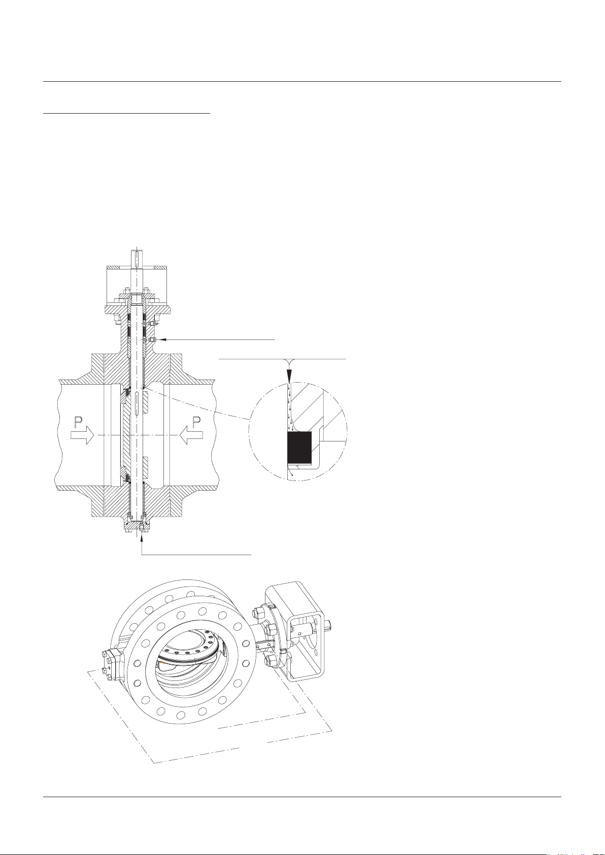
4.1 Bearing and packing flushing
4.1.1 Bearing flushing
The bearing flushing option is obtained by
adding two tapped holes, one in the bottom
flange and one in the neck of the valve
(seefig.9). This option includes the introduction
of a lantern ring at the bottom of the valve
packing. Bearing flushing is recommended
when the valve is installed in a service where
the particles present in the fluid or the line
fluid itself can migrate into the shaft/bearing
area causing problems. A typical example is
sulphur recovery services, where the sulphur
in a liquid or gaseous state may enter this area
and crystallise as a consequence of the plant
shutdown.
Flush pressure = P + 5%
This crystallisation may result in an increase
in the torque requirement of the valve. Another
example may be a fluid that contains particles
(e.g. catalyst) that may cause similar problems
to those highlighted above.
In these types of situations the bearing
flushing may be used to introduce an inert fluid
compatible with the process via the bearing
flush taps (see fig. 8) so as to create a pressure
barrier which prevents the introduction of the
unwanted products from the line into the shaft/
bearing area. The pressure of the flushing fluid
must be slightly higher than the line pressure
(i.e.P1+ approx5%). This both acts as a safety
measure and is a positive step in increasing
the lifetime of the valve, as well as maintaining
the constant torque requirement and hence
operability of the valve.
The bearings may be continuously flushed,
this is recommended by Vanessa for critical
services such as described above. Periodic
flushing may be used for less critical services
in order to clean the bearing/shaft interface or
in order to prepare the valve for a shutdown of
the process.
The bearing flush taps may also be used to
introduce a lubricant compatible with the
process to the bearing areas for high cycle or
dry gas service. The presence of the bearing
protector drastically reduces the consumption
of the flushing or lubricant by reducing the
amount of fluid required to give efficient service
(see fig. 8).
Further information is available from Vanessa
on request.
FIGURE NO. 8
FIGURE NO. 9
Lower flushing inlet
Upper bearing flushing connection
Lower bearing flushing
connection
The bearing protector
minimizes the consumption
of the clean fluid
Packing flushing
connection
9
Page 10

VANESSA SERIES 30,000
InstallatIon and MaIntenance InstructIons
4.1.2 Packing flushing
The packing flushing option is obtained
by the introduction of a tapped hole that
communicates directly to the packing set in the
neck of the valve via a lantern ring. This option
can be used to monitor the rate of emission
of the line fluid toward the atmosphere (it is
important to point out that the packing of the
Vanessa valve fully complies with TA Luft and
EPA requirements). This flush tap may also be
used to capture and evacuate line fluid so as to
prevent any atmospheric loss, with the lantern
ring and split packing configuration acting as a
double block and bleed unit.
A suitable fluid may also be introduced via the
packing flush tap into the packing area so as
to eliminate any possible fugitive emissions
(seefig. 9). By keeping the fluid pressurized at a
pressure that is higher with respect to the line
pressure, the passage of any line fluid towards
the atmosphere can be effectively blocked
giving the valve excellent fugitive emissions
control. However, the fluid used must be
compatible with the line fluid as it may have the
possibility of finding its way into the line as well
as toward the atmosphere.
As with the bearing flushing option this
may also be used to introduce a lubricant
compatible with the process.
4.3 Live loaded packing
The live loaded packing option is designed
to supplement the already excellent
characteristics of the Vanessa valve packing.
This option guarantees a constant compression
of the packing set giving a further guarantee of
the fugitive emissions control of the Vanessa
valve. The fact that the packing is subject to a
near constant force supplied by the Belleville
washers reduces the maintenance cycle
required by the packing (see fig. 10).
Care should be taken in replacing the Belleville
springs as their order (parallel or series)
should be noted.
The packing nuts should be tightened in
accordance with Table I.
At this point it is worth mentioning that the
TALuft test has shown that the Vanessa Series
30,000std. Packing is more than adequate in
passing its stringent requirements.
The live loaded packing option should be
considered in valves that are subject to severe
cycling duty or valves that are subject to severe
thermal cycles.
The drawing shows typical set ups for the live
loaded packing option.
The type of lubricant used for flushing is at
the clients’ care. Vanessa may be contacted
to supply further detailed, process specific
information.
FIGURE NO. 10
10
Page 11

VANESSA SERIES 30,000
InstallatIon and MaIntenance InstructIons
TABLE I: Torque values for gland nuts
ND Trim A Trim B Trim C Trim D Trim E
in. mm Nm ft·lb Nm ft·lb Nm ft·lb Nm ft·lb Nm ft·lb
3 80 - - 15 11 15 11 30 22 - 4 100 - - 15 11 15 11 30 22 - 6 150 - - 15 11 20 15 35 26 50 37
8 200 - - 15 11 20 15 60 44 105 78
10 250 - - 25 18 20 15 70 52 135 100
12 300 - - 25 18 25 18 75 55 240 177
14 350 - - 30 22 30 22 75 55 240 177
16 400 - - 30 22 35 26 100 74 175 129
18 450 - - 35 26 40 30 205 151 480 354
20 500 - - 35 26 45 33 320 236 195 144
24 600 - - 45 33 55 41 420 310 605 446
28 700 30 22 85 63 100 74 465 343 - 30 750 30 22 105 78 135 100 485 358 - 32 800 30 22 105 78 165 122 505 372 - 36 900 30 22 110 81 220 162 545 402 - 40 1000 30 22 110 81 225 166 - - - 42 1050 30 22 110 81 230 170 - - - 48 1200 30 22 110 81 235 173 - - - 54 1350 50 37 155 115 - - - - - 60 1500 65 48 160 118 - - - - - 64 1600 65 48 - - - - - - - 72 1800 65 48 - - - - - - - 84 2100 65 48 - - - - - - - -
Note: the torque values are those suggested for the hydraulic test of the body.
TABLE IV: Lubrication
Type Component to lubricate
Light mineral oil
®
Molykote
Molykote®spray - 321R (dry lubricant) or
equivalent
- P74 (grease) or equivalent
1. Packing rings (5a)
2. Disc surface areas (2a) for seal ring and spiral wound
gasket location
3. Spiral wound gasket (6c)
1. Stud bolts/nuts (5d)
2. Screw (6b)
1. Seal ring (3a)
2. Body seat
TABLE II: Tightening torque values for bolts
and screws
Bolt
dimensions
(mm)
8 12 9
10 24 18
12 41 30
14 66 49
16 103 76
18 142 105
20 201 148
22 274 202
24 348 257
Torque values
Torque
(Nm)
Torque
(ft·lb)
TABLE III: General torque values for bolting
Bolt
dimensions
(mm)
6 10 7
8 20 15
10 45 33
12 70 52
14 110 81
16 175 129
18 235 173
20 335 247
22 370 273
24 460 339
27 595 439
30 760 561
33 785 579
36 1010 745
39 1315 970
42 1625 1199
45 2035 1501
Torque values
Torque
(Nm)
Torque
(ft·lb)
Neither Emerson, Emerson Automation Solutions, nor any of their affiliated entities assumes responsibility for the selection, use or maintenance of any product.
Responsibility for proper selection, use, and maintenance of any product remains solely with the purchaser and end user.
Vanessa is a mark owned by one of the companies in the Emerson Automation Solutions business unit of Emerson Electric Co. Emerson Automation Solutions, Emerson
and the Emerson logo are trademarks and service marks of Emerson Electric Co. All other marks are the property of their respective owners.
The contents of this publication are presented for informational purposes only, and while every effort has been made to ensure their accuracy, they are not to be
construed as warranties or guarantees, express or implied, regarding the products or services described herein or their use or applicability. All sales are governed by
our terms and conditions, which are available upon request. We reserve the right to modify or improve the designs or specifications of such products at any time without
notice.
Emerson.com/FinalControl
11
 Loading...