

Page 1
Instruction Sheet
STAS Steel Take-Apart Shell with
PA-00105
October 2011
Replaceable Filter-Drier Blocks and Filters
STAS Steel Take-Apart Shell with Replaceable Filter-Drier Blocks and Filters
Safety Instructions
1. Read Installation Instructions thoroughly. Failure to
follow instructions may result in drier failure or system
damage.
2. Do not remove blocks from can until just prior to installations. Early removal could result in contamination of
the desiccant from surrounding atmosphere.
3. Checkarrowforcorrectowdirection.Reverse ow
may cause internal damage.
4. CAUTION: In a severely contaminated system avoid
breathing acid vapors, and avoid contact with the skin
or clothing from contaminated refrigerant. Dispose the
contaminated refrigerant in a caustic solution. Failure
to do so may cause personal injury.
Liquid Line Service
1. For best results install the STAS steel take-apart
shell in the liquid line between the receiver and the
moisture-liquid indicator, solenoid valve and thermal
expansion valve. The STAS shell may be mounted in
any position; but the horizontal position is preferred
inthatanycontaminantscollectedbythelter-drier
blocks will be more easily removed when installing
newlter-drierblocks.
NOTE: The side connection of the STAS shell must always
be the inlet when used on liquid line service to ensure
system protection from possible block rupture.
5. Thoroughly leak test system after installation. Failure
to do so could result in loss of refrigerant.
6. These products are intended for use on CFC, HCFC,
and HFC refrigerants.
DonotuseEmersonlter-driersonanyotherun-
listedgasoruidmediawithoutpriorapprovalofthe
Emerson Climate Technologies Flow Controls Division
ApplicationsEngineeringDepartment.Useonuids
not listed could result in chemical deterioration of the
lter-drier.
7. The products listed in the bulletin should not be used
for hot gas applications.
Suction Line Service
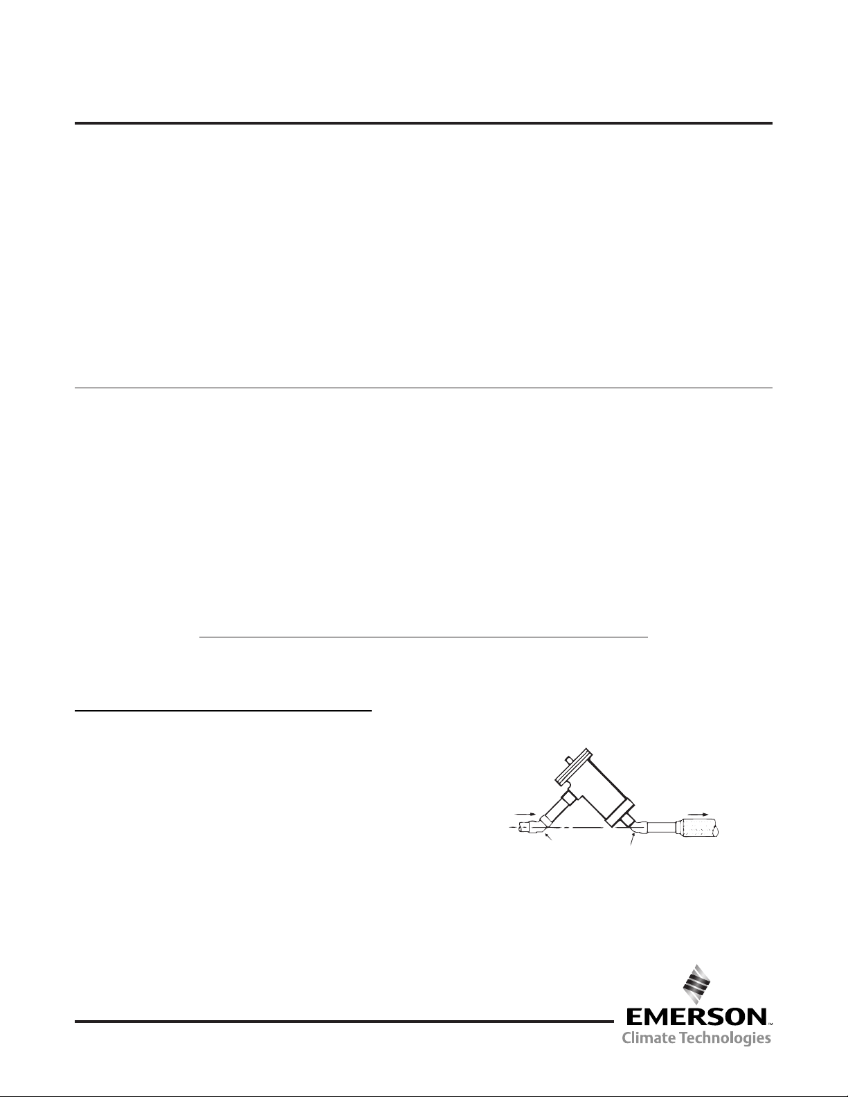
1. Locate the STAS shell in the suction line as close as
possible to the compressor, but upstream of any vibration eliminator that might be present. Install the shell in
a vertical position (outlet down), or as show in Figure 1
which permits oil return to the compressor and convenient removal of the internal hardware assembly.
NOTE: The side connection of the STAS shell must
alwaysbetheinletwhenconventionalsuctionltersare
used,orwhenlter-drierblocksareusedforburnout
clean-up. The side connection may be used as an outlet
ttingonly when a reverse ow lter, F-48R, will be used
to prevent possible rupture with resulting discharge into
the compressor.
1. Install the shell in a location that affords adequate
clearancetoremovetheentireoutletretainer/lter-
drier block assembly as noted below:
SHELL SIZE REQUIRED CLEARANCE
STAS-48 7 ¼”
STAS-96 12 ¾”
STAS-144 18 ¼”
STAS-192 23 ¾”
2. Removal of the internal components of the STAS shell
is not required before brazing into the system.
3. Purge an inert gas such as nitrogen thru the lines
while brazing to prevent formation of copper oxides.
DO NOT USE OXYGEN.
4. High temperature brazing alloys may be used as the
STASttingsaresolidcopper.Normalprecautions
shouldbetakenbydirectingtheameawayfromthe
lter-driershell,andtheuseofchillblocks,wetrags
or other suitable heat protection to minimize damage
tothepaintsurfacesadjacenttothettingsisrecommended.
www.emersonclimate.com/owcontrols
5. Test for leakage.
6. Installthelter-drierblocksasnotedonpage2.
NOTE:Ontheinitialinstallationofeitherlter-drierblocks
orltersthecardboardspacersusedtosecurethe
inlet retainer (and couplings as required) should be
discarded.
From
Evaporator
45° Elbow
Copper Sweat
Figure 1
To
Compressor
45° Street Elbow
Copper Sweat
11911 Adie Road P.O. Box 411400 St. Louis MO 63141 USA CUSTOMER SERVICE (314) 569-4666
Page 2
Installation Instructions for Replaceable Filter-Drier Blocks and Filters
DO NOT OPEN BAG UNTIL READY TO INSTALL BLOCK OR SUCTION FILTER CORE
FELT OR GASKET
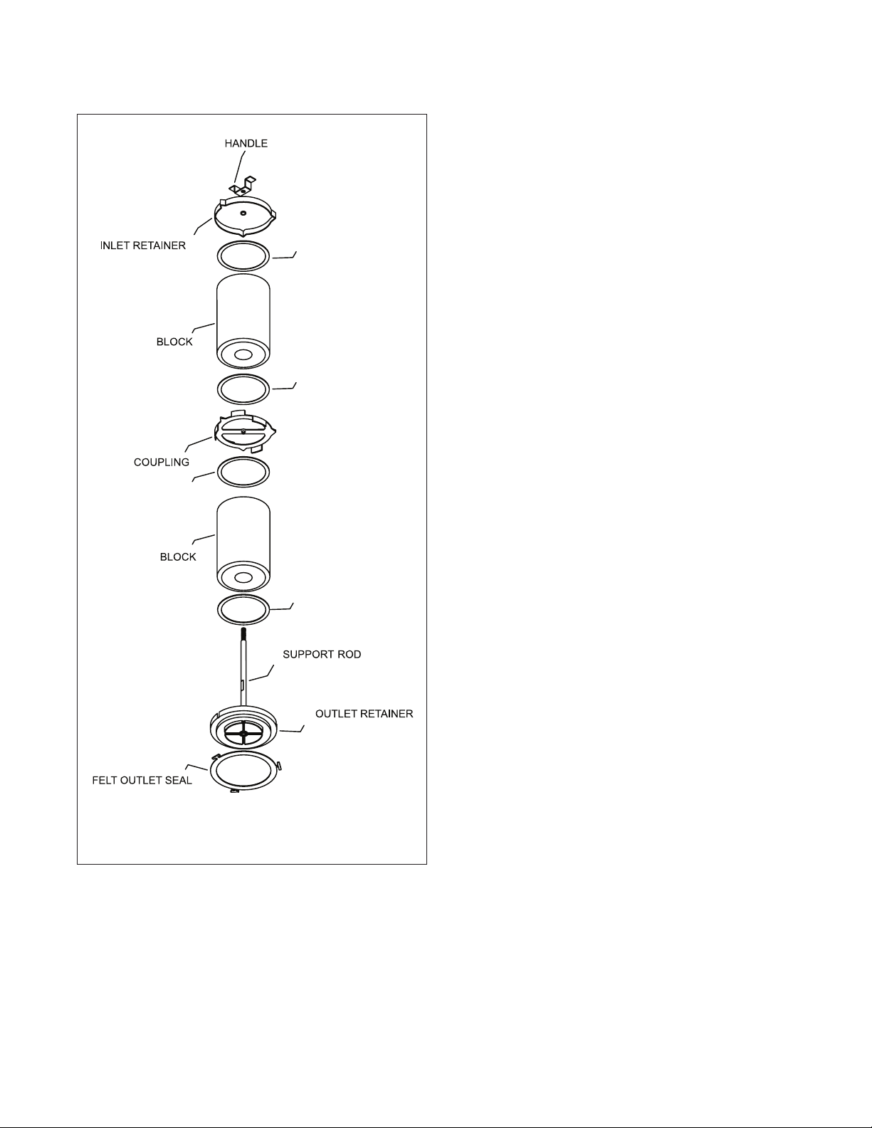
STAS Exploded View
with STAS Series Take-Apart Shells
1. Pump down the system and the STAS shell completely.
2. Remove the cover bolts, cover, and examine the cover
gasket. If the gasket surface is damaged as indicated by
material adhering to the end of the shell the old gasket
must be discarded.
3. Withdraw the internal assembly by pulling on handle.
4. Disassemble internal assembly by unscrewing handle
while holding inlet retainer.
FELT OR GASKET
FELT OR GASKET
FELT OR GASKET
5. Removecontaminatedlter-drierblockorsuctionlter.
For multiple block or core units remove coupling.
6. Clean all internal parts thoroughly, giving particular care
and attention to the outlet screen.
NOTE: The ring seal is secured to outlet retainer and should
not be replaced unless it has been severely contaminated as
a result of a severe burnout.
7. Removeblockorlterfromitspackagingandreassemble
as rapidly as possible to minimize moisture contamination.
8. Install the new core in the outlet retainer taking care
to place the end of the block with the tapered inside
diameter against the outlet retainer. With multiple block
or core units place coupling between each block or core.
Positiontheinletretaineroverthenalblockorcore,and
screwthehandlermlyinplace.Carefullyinserttheas-
sembled unit into the shell assembly.
9. Lightlycoattheexistingcovergasketintheangecover
with refrigeration grade oil if determined in step 2 to be
suitable for reuse, or lightly coat a new gasket on both
surfacesandcarefullyplaceinthegrooveoftheange
cover.
10. Push the cover against the shell assembly taking care to
locate the compression spring against the inlet retainer
without hanging-up on the handle. Install a cover bolt in
the shell. Using the slotted hole with the installed bolt,
install the cover placing a cover bolt in the diagonally opposite bolt hole to hold the cover snugly against the shell
edge.
11. Install the remaining cover bolts snugly.
12. Torque all cover bolts evenly in a criss-cross pattern to
a torque of 30 ft. lbs. Maximum. [25 ft. lbs. maximum
for the S-V suction line series which have stainless steel
bolts.]
13. Test for leakage.
14. Start the compressor and put the system in operation.
After system operation has stabilized check the moisture-
indicatortoverifythatasufcientamountofrefrigerantis
available.
NOTE:Onsuctionlinelterservicerecordthepressuredrop
acrosstheSTASonthespeciallabelsuppliedwiththelter
core and apply to the side of the shell assembly.
WARNING: DO NOT USE SUCTION FILTERS ON LIQUID
LINE APPLICATIONS.
Page 3
Compressor Motor Burnout Clean-Up Procedure Suction Line Filter-Drier Method
1. Determine the extent of the burnout. For mild burnouts
where contamination has not spread through the system,
it may be economical to save the refrigerant. Normally
it is not economical to save the refrigerant charge if the
system used less than 25 pounds of refrigerant.
A severe burnout exists if the oil is discolored, an acid
odor is present and contamination products are found in
the high and low side. With this condition caution should
be exercised to avoid breathing the acid vapors and avoid
contact with the skin of contaminated liquid. Dispose of
the contaminated refrigerant in a caustic solution.
2. Thoroughly clean and replace all system controls such as
thermal expansion valves, solenoids, check valves, re-
versingvalves,etc.Removeallstrainersandlter-driers.
3. Install replacement compressor and make a complete
electrical check.
4. Make sure the suction line adjacent to compressor is
clean. Install an Emerson STAS suction line shell com-
pletewithnewlter-drierblocks.Installanewoversized
Emersonliquidlinelter-drier.
5. Pressurize and leak-test the system according to unit
manufacturer’s recommendations.
6. Triple evacuate to a least 50 microns. Break the vacuum
with clean, dry refrigerant at 0 psig.
7. Charge the system to equipment manufacturer’s recommendations.
8. Start the compressor and put the system in operation.
Record the pressure drop across the STAS suction line
shell on the enclosed label and apply to the side of the
shell.
9. Replacethesuctionlinelter-drierblocksifthepressure
drop becomes excessive.
10.Observethesystemduringtherstfourhours.Repeat
step 9 as often as required until no further change in
pressure drop is observed.
11. After the system has been in operation for 48 hours,
check the condition of the oil with the Acid Alert test kit.
If the oil test indicates an acid condition, replace both the
liquidandsuctionlinelter-drier.
12. Check the system again after approximately two weeks
of operation. If the oil is still discolored, replace the liquid
andsuctionlinelter-drier.
13. Clean-up is complete when the oil is clean and odor free,
and is determined to be acceptable with the Acid Alert
test kit.
14.Replacethesuctionlinelter-drierblockswithsuction
linelterstominimizesuctionlinepressuredrop,butstill
providing compressor protection.
For detailed burnout clean-up procedure and recommendations, consult the RSES Service Manual Section 91.
NOTE: Allow the liquid-line lter-drier to remain in the
system for continued compressor protection.
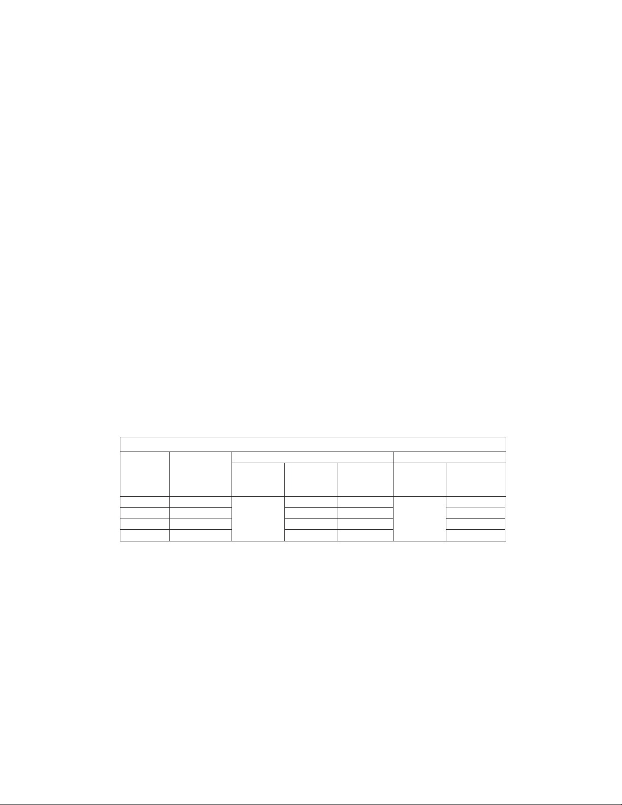
STAS Series Specications
Filter-Drier Service Suction Filter Service
STAS Required Desiccant
Shell # of Blocks Filter-Drier Volume Filter Area Suction Filter Area
or Cores Blocks Cu. In. Sq. In. Filter Sq. In.
STAS-48 1 48 69 105
D-48
STAS-96 2 96 138 F-48 210
H-48
STAS-144 3 144 207 F-48R 315
W-48
STAS-192 4 192 276 420
Page 4

 Loading...