

Emerson SW350, SR330, SW375 Owner's Manual
Part No. F40BP72530002 Form No. BP7253-2
READ AND SAVE THESE INSTRUCTIONS
SW350, SR330 & SW375
Ceiling Fan/Light
Wall Control, Remote Control &
Receiver Owner's Manual
For use only with Emerson Ceiling Fan Models: F2100 2, F2200 2, F2300 1,
CF1 1, CF2300 1, CF2400 1, CF2454 2, CF2500 1, CF2600 2, CF2650 0,
CF2675 1, CF3500 0, CF3900 1, CF4500 4, CF4600 0 and CF4800 3.
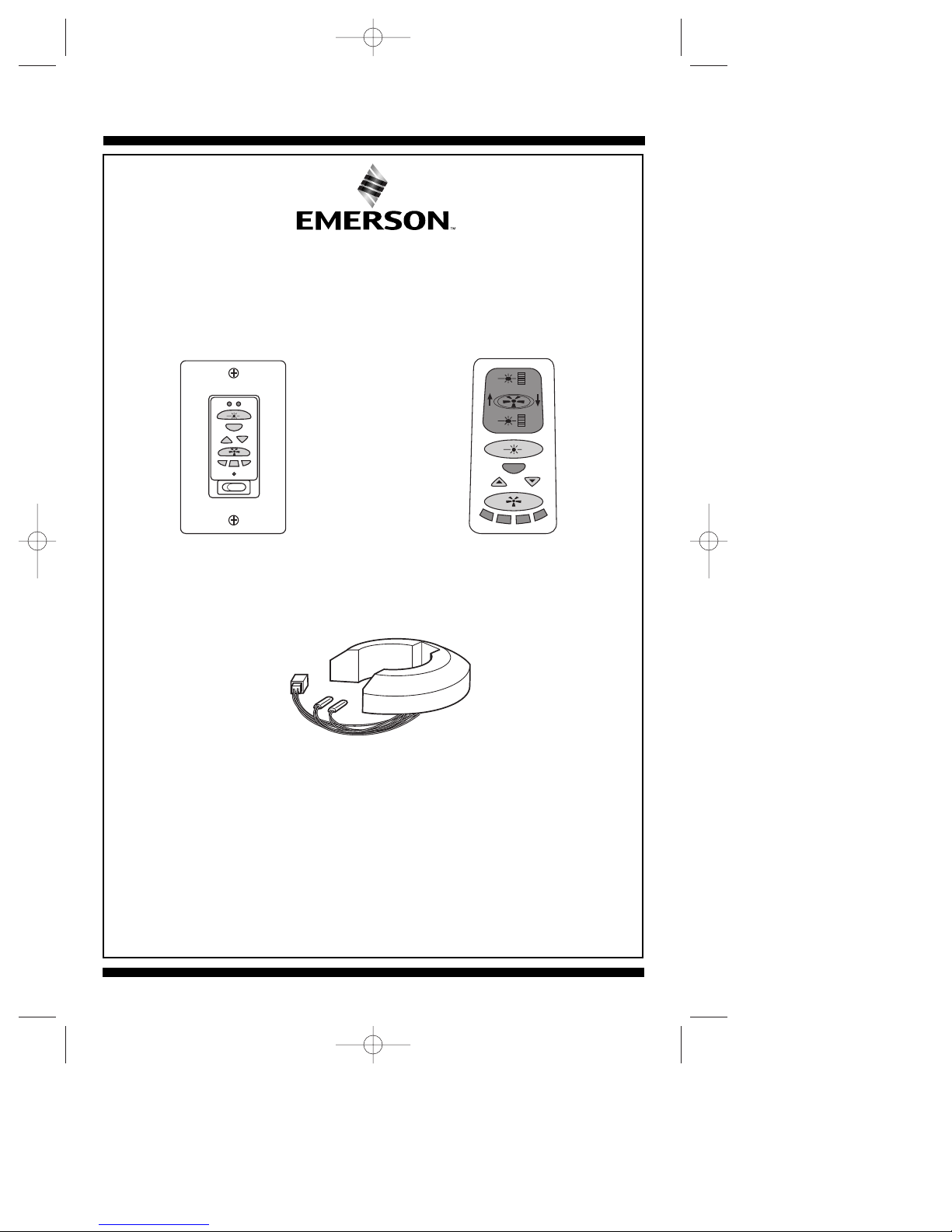
Model
SW350
Wall Control
Model
SR330
Remote Control
Model
SW375
Receiver
NOTE: The SW350 and SR330 controls
must be used with a SW375 receiver.
BP7253-2 4/28/06 11:58 AM Page 1
Up Light
Up Down
Lights
S
e
l
t
e
c
Fan
y
F
t
i
l
r
o
u
w
c
e
S
Sleep
Off On
Fan High
Air
UP
A
i
r
f
l
o
w
Air
Fan Low
DN
Down Light
Lights
S
t
e
l
c
e
Fan
r
e
t
n
i
W
S
y
t
l
e
uri
e
p
c
S
e
2
Safety Instructions
WARNING: To avoid fire, shock, and serious personal injury, follow all instructions
carefully.
1. Read your Owner's Manual carefully before installing the Remote Control, Wall
Control, or Receiver. Retain Owner's Manual for future reference.
2. Before servicing or cleaning the ceiling fan, switch power off at service panel and lock
service panel to prevent power from being switched on accidentally. When the service
disconnecting means cannot be locked, securely fasten a warning device such as a
tag, to the service panel.
ADDITIONAL SAFETY INSTRUCTIONS FOR INSTALLATION
1. To avoid possible electrical shock, be sure electricity is turned off at the main fuse or
circuit breaker box before wiring.
2. Make certain no bare wires are exposed outside the wire connectors.
3. All wiring must conform to National and Local Electrical Codes.
4. Follow the recommended instructions for the proper method of wiring your new
Remote Control, Wall Control, or Receiver. If you feel you do not have enough
electrical wiring knowledge or experience, have your Remote Control, Wall Control, or
Receiver installed by a licensed electrician. Any electrical work not described in this
manual should be performed by a licensed electrician.
WARNING
!
DATE CODE:
The date code of this fan may be found on the box, stamped in ink on a white label.
You should record this data above and keep it in a safe place for future use.
INSTRUCTION T
O THE USER (if device contains a digital device)
This equipment has been tested and found to comply with the limits for a class B digital
device, pursuant to part 15 of the FCC Rules. These limits are designed to provide reasonable
protection against harmful interference in a residential installation. This equipment generates,
uses and can radiate radio frequency energy and if not installed and used in accordance with
the instructions, may cause harmful interference to radio communications. However, there is
no guarantee that interference will not occur in a particular installation. If this equipment does
cause harmful interference to radio or television reception, which can be determined by
turning the equipment off and on, the user is encouraged to try to correct the interference by
one or more of the following measures:
• Reorient or relocate the receiving antenna.
• Increase the separation between the equipment and receiver.
• Connect the equipment into an outlet on a circuit different from that to which the receiver
is connected.
• Consult the dealer or an experienced radio/TV technician for help.
This equipment has been certified to comply with the limits for a class B computing device,
pursuant to FCC Rules. In order to maintain compliance with FCC regulations, shielded cables
must be used with this equipment. Operation with non-approved equipment or unshielded
cables is likely to result in interference to radio and TV reception. The user is cautioned that
changes and modifications made to the equipment without the approval of manufacturer could
void the user’s authority to operate this equipment.
This Class B digital apparatus meets all requirements of the Canadian
Interference-Causing Equipment Regulations.
BP7253-2 4/28/06 11:58 AM Page 2
3
General
Installation to Operate the
Ceiling Fan, Downlight
and Uplight
Your Emerson Ceiling Fan/Light Control
consists of either a hand-held transmitter
with wall caddy and/or a wall control as
well as a receiver which is mounted under
the fan ceiling cover. The wall control and
remote control are designed to control
your ceiling fan speed, airflow direction,
and light intensity.
IMPORTANT
It is important that you also follow the
instructions found in the Owner's
Manual supplied with your Ceiling Fan.
Pay particular attention to the Safety
Instructions and WARNING notes.
NOTE 1: On the CF4600 Series Ceiling
Fan, install the fan blades and switch
cup assembly in accordance with the
instructions in the ceiling fan owner’s
manual, then proceed with steps 1
through 10 below.
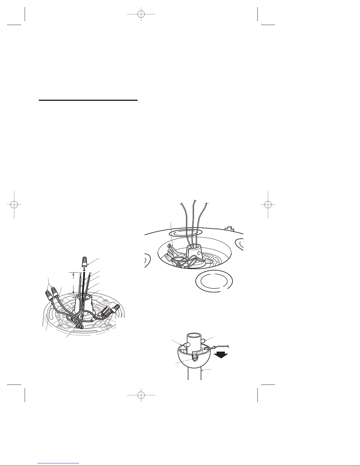
1. Remove the wire connectors from the
red and brown wires. Cut the white,
blue and black wires about 3" above
the motor coupling (Figure 1). Strip
insulation 1/2" from end of white, blue,
red and brown wires. Install a wire
connector on the black wire; this wire
will not be used.
Figure 1
NOTE 2: On Model CF1, CF2400, and
CF2800 Series Ceiling Fans, the red
and brown wires from the motor are
connected to red and brown wires from
the reversing switch. Remove the wire
connectors and separate these wires.
Using wire connectors, cap the red and
brown wires from the reversing switch;
these wires will not be used.
NOTE 3: If your ceiling fan does not
have a built-in uplight, these yellow
wires will not be present.
2. Remove the wire connector (Figure 1)
from the yellow wires (See NOTE 3).
Separate the yellow wires, and cap the
yellow wire coming from the motor
coupling.
NOTE 4: On early Model CF2400 Series
Ceiling Fans, cut the orange wire
midway between the motor coupling
and the housing (Figure 2). Cap the
orange wire from the motor coupling
using a wire connector. The orange
wire from the housing will get
connected to the uplight yellow wire in
Step 6.
3. Loosen the setscrew in the hanger ball,
slide the ball down the hanger pipe,
and remove the clevis pin. Then slide
the hanger ball off the hanger pipe
(Figure 3). Retain all parts.
DOWNROD
CLEVIS PIN
SETSCREW
HANGER
BALL
Figure 3
Figure 2
BP7253-2 4/28/06 11:58 AM Page 3
REMOVE WIRE
CONNECTORS
FROM RED AND
BROWN WIRES
(See NOTE 1)
BROWN
3"
WIRE
RED WIRE
YELLOW WIRE FROM MOTOR
COUPLING (See NOTE 3)
CAP BLACK WIRE
USING A WIRE
CONNECTOR
BLACK WIRE
WHITE WIRE
BLUE WIRE
MOTOR COUPLING
YELLOW WIRE
FROM UPLIGHT
(See NOTE 3)
ORANGE WIRE
(See NOTE 3)
REMOVE
WIRE
CONNECTOR
7. Fold the wires of the wiring harnesses
into the slot in the motor coupling, slide
the hanger pipe down the wires and
seat the hanger pipe in the motor
coupling.
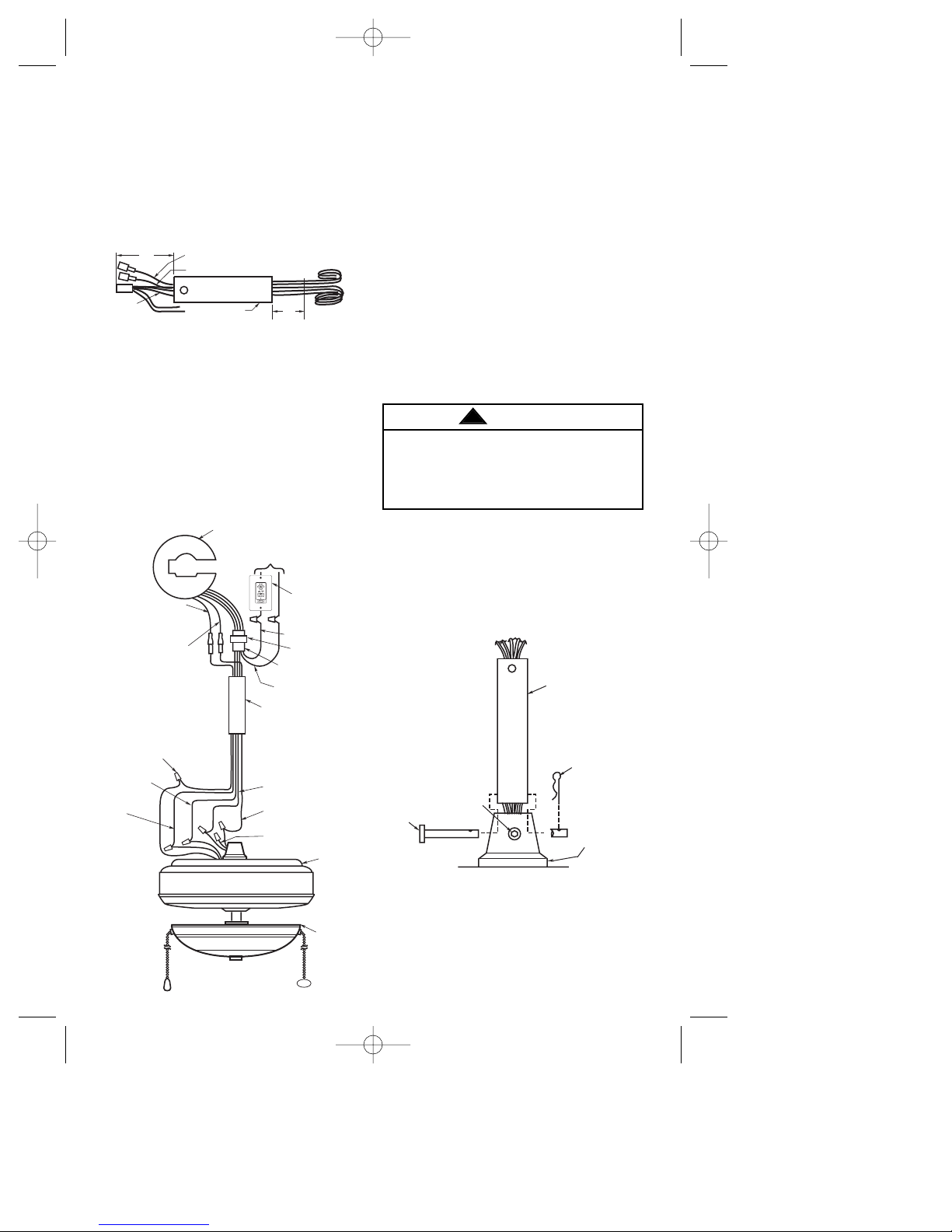
8. Align the clevis pin holes in the hanger
pipe with the holes in the motor
coupling. Install the clevis pin and
secure with the hairpin clip. The clevis
pin must go through the holes in the
motor coupling and the holes in the
hanger pipe (Figure 6). Push the
straight leg of the hairpin clip through
the hole near the end of the clevis pin
until the curved portion of the hairpin
clip snaps around the clevis pin. The
hairpin clip must be properly installed to
prevent the clevis pin from working
loose.
9. Install the setscrew (supplied in loose
parts bag supplied with ceiling fan) in
the motor coupling and tighten using
the 5/32" setscrew wrench (supplied
with ceiling fan) (Figure 6). A loose
setscrew could cause the fan to
wobble.
10. Screw the two threaded studs (select
the proper length stud as described in
the Ceiling Fan Owner’s Manual) into
the threaded holes in top of the motor.
(Figure 7). (Early motors have two
threaded brackets.) Coil the wires and
4
4. Push the wiring harness connector
(supplied with the SW375 receiver) and
the connectors on the blue wire
(supplied with the control) and yellow
wire (supplied with fans containing
built-in Uplights) through the hanger
pipe until they extend about 4" out of
the pipe (Figure 4).
5. Cut the harness wires approximately 3"
from the end of the pipe. Strip
insulation 1/2" from end of wires.
6. Using wiring connectors supplied,
connect the white, red, yellow, blue, and
brown wires of the wiring harness to the
white, red, yellow (orange wire for early
CF2400 Models), blue, and brown wires
of the ceiling fan (Figure 5). Wires must
be connected color-to-color.
It is critical that the clevis pin in the
motor coupling is properly installed and
the setscrew securely tightened. Failure
to verify that the pin is properly installed
could result in the fan falling.
WARNING
!
Figure 6
Figure 4
BLUE WIRE TO
BLUE WIRE
Off On
Up Down
Lights
Fan
Sleep
FAN BLADES REMOVED
FOR CLARITY
HANGER
PIPE
WHITE WIRE
BLACK WIRE
WIRING HARNESS
CONNECTOR
YELLOW WIRE
TO YELLOW
WIRE (Built-in
Up Light Only)
BLUE WIRE TO
BLUE WIRE
SW375 RECEIVER
TO
120V SUPPLY
BROWN WIRE
TO BROWN
WIRE
YELLOW WIRE
TO YELLOW WIRE*
(Built-in Up Light Only)
SW350
WALL CONTROL
OR
ON/OFF WALL
SWITCH
RECEIVER
CONNECTOR
BLACK WIRE
(NOT USED)
RED WIRE TO
RED WIRE
WHITE WIRE TO
WHITE WIRE
LIGHT
FIXTURE
FAN
HOUSING
* ON SOME CF2400 MODELS,
THE WIRE FROM MOTOR
MAY BE ORANGE
Figure 5
BP7253-2 4/28/06 11:58 AM Page 4
YELLOW LEAD (Built-in Up Light Only)
(See NOTE 3)
4"
BLUE WIRE
CUT HERE
WIRING
HARNESS
DOWNROD
3"
HANGER PIPE
CLEVIS
PIN
SETSCREW
HAIRPIN
CLIP
MOTOR
COUPLING
 Loading...