

Emerson SP3201, SP2203, SP2202, SP3202, SP4202 Installation Manual
...
Installation Guide
U
Regen
200V, 400V, 575V, 690V
Part Number: 0471-0029-02
Issue: 2
www.controltechniques.com

General Information
The manufacturer accepts no liability for any consequences resulting from inappropriate, negligent or incorrect
installation or adjustment of the optional operating parameters of the equipment or from mismatching the variable speed
drive with the motor.
The contents of this guide are believed to be correct at the time of printing. In the interests of a commitment to a policy
of continuous development and improvement, the manufacturer reserves the right to change the specification of the
product or its performance, or the contents of the guide, without notice.
All rights reserved. No parts of this guide may be reproduced or transmitted in any form or by any means, electrical or
mechanical including photocopying, recording or by an information storage or retrieval system, without permission in
writing from the publisher.
Drive software version
This product is supplied with the latest version of software. If this product is to be used in a new or existing system with
other drives, there may be some differences between their software and the software in this product. These differences
may cause this product to function differently. This may also apply to drives returned from a Control Techniques Service
Centre.
The software version of the drive can be checked by looking at Pr 11.29 (or Pr 0.50) and Pr 11.34. The software version
takes the form of zz.yy.xx, where Pr 11.29 displays zz.yy and Pr 11.34 displays xx, i.e. for software version 01.01.00,
Pr 11.29 would display 1.01 and Pr 11.34 would display 0.
If there is any doubt, contact a Control Techniques Drive Centre.
Environmental statement
Control Techniques is committed to minimising the environmental impacts of its manufacturing operations and of its
products throughout their life cycle. To this end, we operate an Environmental Management System (EMS) which is
certified to the International Standard ISO 14001. Further information on the EMS, our Environmental Policy and other
relevant information is available on request, or can be found at www.greendrives.com.
The electronic variable-speed drives manufactured by Control Techniques have the potential to save energy and
(through increased machine/process efficiency) reduce raw material consumption and scrap throughout their long
working lifetime. In typical applications, these positive environmental effects far outweigh the negative impacts of product
manufacture and end-of-life disposal.
Nevertheless, when the products eventually reach the end of their useful life, they can very easily be dismantled into their
major component parts for efficient recycling. Many parts snap together and can be separated without the use of tools,
while other parts are secured with conventional screws. Virtually all parts of the product are suitable for recycling.
Product packaging is of good quality and can be re-used. Large products are packed in wooden crates, while smaller
products come in strong cardboard cartons which themselves have a high recycled fibre content. If not re-used, these
containers can be recycled. Polythene, used on the protective film and bags for wrapping product, can be recycled in the
same way. Control Techniques' packaging strategy favours easily-recyclable materials of low environmental impact, and
regular reviews identify opportunities for improvement.
When preparing to recycle or dispose of any product or packaging, please observe local legislation and best practice.
Copyright © February 2007 Control Techniques Drives Limited
Issue Number: 2
Software: 01.07.01 onwards
How to use this guide
System design
Programming
and
commissioning
This user guide provides complete information for installing and operating a Unidrive SP from start to finish.
The information is in logical order, taking the reader from receiving the drive through to fine tuning the performance.
NOTE
There are specific safety warnings throughout this guide, located in the relevant sections. In addition, Chapter 1 Safety
Information contains general safety information. It is essential that the warnings are observed and the information
considered when working with or designing a system using the drive.
This guide should be read in-line with the relevant User Guide also, which contains additional information which may be
required whilst designing and commissioning a regen system.
This map of the user guide helps to find the right sections for the task you wish to complete:
1 Safety information
2 Introduction
3 Product information
4 System design
5 Mechanical Installation
6 Electrical installation
7 Getting started
8 Optimisation
9 Parameters
Familiarisation System design
commissioning
Programming
and
Troubleshooting
10 Technical data
11 Component sizing calculations
12 Diagnostics

Contents
1 Safety Information .................................6
1.1 Warnings, Cautions and Notes .............................6
1.2 Electrical safety - general warning ........................6
1.3 System design and safety of personnel ................6
1.4 Environmental limits ..............................................6
1.5 Compliance with regulations .................................6
1.6 Special note on SECURE DISABLE/ENABLE
function in regen operation ....................................6
1.7 Adjusting parameters ............................................6
2 Introduction ............................................7
2.1 Regen operation ....................................................7
2.2 Advantages of Unidrive SP operating in regen
mode .....................................................................7
2.3 Principles of operation ...........................................7
2.4 Power flow .............................................................8
2.5 Synchronisation .....................................................8
2.6 Current trimming ...................................................8
2.7 Regen system configurations ................................8
2.8 Regen drive system types .....................................9
3 Product Information ............................12
3.1 Model number .....................................................12
3.2 Nameplate description ........................................12
3.3 Ratings ................................................................13
3.4 Drive features ......................................................17
3.5 Unidrive SPMC half controlled thyristor rectifier ..19
3.6 Unidrive SPMC/U technical data .........................20
3.7 Output Sharing Chokes (for motoring drives
only) ....................................................................22
3.8 Options ................................................................23
3.9 Items supplied with the drive ...............................25
3.10 Regen components .............................................25
4 System design .....................................30
4.1 Introduction .........................................................30
4.2 Power connections ..............................................30
4.3 Non standard applications ...................................40
4.4 Cable length restrictions ......................................40
4.5 Cable types and lengths ......................................42
4.6 Exceeding maximum cable length ......................42
5 Mechanical Installation .......................45
5.1 Safety information ...............................................45
5.2 Planning the installation ......................................45
5.3 Regen component dimensions ............................46
5.4 External EMC filter .............................................55
5.5 Enclosure ............................................................62
5.6 Cubicle design and drive ambient temperature ...64
6 Electrical Installation .......................... 65
6.1 Power connections ............................................. 66
6.2 AC supplies ........................................................ 74
6.3 Cable and fuse ratings ....................................... 75
6.4 EMC (Electromagnetic compatibility) ................. 77
6.5 External EMC filter ............................................. 78
6.6 Control connections ........................................... 83
7 Getting started .................................... 86
7.1 Regen parameter settings .................................. 86
7.2 Regen drive sequencing .................................... 86
7.3 Regen drive commissioning ............................... 87
7.4 Motoring drive commissioning ............................ 88
8 Optimisation ........................................ 89
8.1 Power feed-forward compensation (Pr 3.10) ..... 89
8.2 Current loop gains .............................................. 89
8.3 Voltage controller gain (Pr 3.06) ........................ 90
8.4 Power factor correction (Pr 4.08) ....................... 91
8.5 Current trimming ................................................ 91
9 Parameters .......................................... 92
9.1 Parameter ranges and variable maximums: ...... 92
9.2 Menu 0: Basic parameters ................................. 93
9.3 Menu 3: Regen sequencer ................................. 94
9.4 Menu 4: Current control ................................... 100
9.5 Menu 5: Regen control ..................................... 107
9.6 Menu 6: Clock .................................................. 111
9.7 Menu 7: Analogue I/O ...................................... 119
9.8 Menu 8: Digital I/O ........................................... 132
9.9 Menu 9: Programmable logic, motorised pot
and binary sum ................................................. 138
9.10 Menu 10: Status and trips ................................ 146
9.11 Menu 11: General drive set-up ......................... 154
9.12 Menu 12: Threshold detectors and variable
selectors ........................................................... 165
9.13 Menu 14: User PID controller ........................... 172
9.14 Menus 15, 16 and 17: Solutions Module set-up 178
9.15 Menu 18: Application menu 1 ........................... 179
9.16 Menu 19: Application menu 2 ........................... 180
9.17 Menu 20: Application menu 3 ........................... 181
9.18 Menu 22: Additional menu 0 set-up ................. 182
10 Technical data ................................... 183
10.1 Drive ................................................................. 183
10.2 Supply requirements ........................................ 191
10.3 Protection ......................................................... 192
10.4 Component data ............................................... 196
10.5 Optional external EMC filters ........................... 199
11 Component sizing ............................. 203
11.1 Sizing of MCB for switching frequency filter ..... 203
11.2 Resistor sizing for multiple drive systems ........ 204
11.3 Thermal / magnetic overload protection for soft
start circuit ........................................................ 204
4 Unidrive SP Regen Installation Guide
www.controltechniques.com Issue Number: 2

12 Diagnostics ........................................206
12.1 Trip indications ..................................................206
12.2 Alarm indications ...............................................215
12.3 Status indications ..............................................215
12.4 Displaying the trip history ..................................215
Unid rive SP Regen Insta llation G uide 5
Issue Number: 2 www.controltechniques.com

Safety
Information
Introduction
Product
information
System
design
Mechanical
installation
Electrical
installation
1 Safety Information
1.1 Warnings, Cautions and Notes
A Warning contains information which is essential for
avoiding a safety hazard.
WARNING
A Caution contains information which is necessary for
avoiding a risk of damage to the product or other equipment.
CAUTION
NOTE
A Note contains information which helps to ensure correct operation of
the product.
1.2 Electrical safety - general warning
The voltages used in the drive can cause severe electrical shock and/or
burns, and could be lethal. Extreme care is necessary at all times when
working with or adjacent to the drive.
Specific warnings are given at the relevant places in this guide.
1.3 System design and safety of
The drive is intended as a component for professional incorporation into
complete equipment or a system. If installed incorrectly, the drive may
present a safety hazard.
The drive uses high voltages and currents, carries a high level of stored
electrical energy, and is used to control equipment which can cause
injury.
Close attention is required to the electrical installation and the system
design to avoid hazards either in normal operation or in the event of
equipment malfunction. System design, installation, commissioning and
maintenance must be carried out by personnel who have the necessary
training and experience. They must read this safety information and this
guide carefully.
The STOP and SECURE DISABLE functions of the drive do not isolate
dangerous voltages from the output of the drive or from any external
option unit. The supply must be disconnected by an approved electrical
isolation device before gaining access to the electrical connections.
None of the drive functions must be used to ensure safety of
personnel, i.e. they must not be used for safety-related functions.
Careful consideration must be given to the functions of the drive which
might result in a hazard, either through their intended behaviour or
through incorrect operation due to a fault. In any application where a
malfunction of the drive or its control system could lead to or allow
damage, loss or injury, a risk analysis must be carried out, and where
necessary, further measures taken to reduce the risk - for example, an
over-speed protection device in case of failure of the speed control, or a
fail-safe mechanical brake in case of loss of motor braking.
personnel
Getting
started
of fuses or other protection, and protective earth (ground) connections.
This guide contains instruction for achieving compliance with specific
EMC standards.
Within the European Union, all machinery in which this product is used
must comply with the following directives:
Optimisation Parameters
98/37/EC: Safety of machinery.
89/336/EEC: Electromagnetic Compatibility.
Technical
data
Component
sizing
Diagnostics
1.6 Special note on SECURE DISABLE/
ENABLE function in regen operation
In regen operation the enable input of the Regen drive stage has no
safety functions. It only enables the active rectifier operation. It does not
disable any operation of the motoring drive(s) and it does not prevent the
regen stage from producing DC power.
The enable input of the motoring drive stage can be used for safety
functions if required. Consult the Unidrive SP User Guide for information
on SECURE DISABLE.
1.7 Adjusting parameters
Some parameters have a profound effect on the operation of the drive.
They must not be altered without careful consideration of the impact on
the controlled system. Measures must be taken to prevent unwanted
changes due to error or tampering.
1.4 Environmental limits
Instructions in this guide regarding transport, storage, installation and
use of the drive must be complied with, including the specified
environmental limits. Drives must not be subjected to excessive physical
force.
1.5 Compliance with regulations
The installer is responsible for complying with all relevant regulations,
such as national wiring regulations, accident prevention regulations and
electromagnetic compatibility (EMC) regulations. Particular attention
must be given to the cross-sectional areas of conductors, the selection
6 Unidrive SP Regen Installation Guide
www.controltechniques.com Issue Number: 2

Safety
Information
Introduction
Product
information
System
design
Mechanical
installation
Electrical
installation
2 Introduction
The following installation guide should be read in conjunction with the
Unidrive SP User Guide.
Any Unidrive SP drive can be configured as an AC Regenerative Unit
(hereafter referred to as a Regen drive).
This guide covers the following:
• Principles and advantages of operation in regen mode
• Safety information
• EMC information
• Detailed information on additional components required
• System design
• Special considerations
• Installation
• Commissioning and optimisation of the completed system
At least two Unidrive SP drives are required to form a complete
regenerative system - one connected to the supply and the second one
connected to the motor. A Unidrive SP in regen mode converts the AC
mains supply to a controlled DC voltage, which is then fed into another
drive(s) to control a motor(s).
NOTE
The motoring drive(s) in a regen configuration could be another drive
other than a Unidrive SP, e.g. Unidrive classic or Commander SK etc.
NOTE
The following regen components are also required in addition to the
Unidrive SP drives.
1. Regen inductor
2. Switching frequency filter inductor
3. Switching frequency filter capacitor
4. Softstart resistor
5. Varistors
6. MCBs
7. Overload relays
Getting
started
Optimisation Parameters
Technical
data
Component
sizing
Diagnostics
• Transient operation is possible between 40 and 72Hz down to the
above supply voltage levels for approximately 1 second.
• The Regen and motoring drives are identical (when using Unidrive
SP).
• Power feed-forward term available, using analogue I/O set-up
• A fast transient response is possible using the power feed forward
term.
2.3 Principles of operation
The input stage of a non-regenerative AC drive is usually an
uncontrolled diode rectifier, therefore power cannot be fed back onto the
AC mains supply. By replacing the diode input rectifier with a voltage
source PWM input converter (Unidrive SP), AC supply power flow can
be bi-directional with full control over the input current waveform and
power factor. Currents can now be controlled to give near unity power
factor and a low level of line frequency harmonics.
In the case of a Unidrive SP operating in regenerative mode, the IGBT
stage is used as a sinusoidal rectifier converting the AC supply to a
controlled DC voltage.
Furthermore, by maintaining the DC bus voltage above the peak supply
voltage the load motor can be operated at a higher speed without field
weakening. Alternatively, the higher output voltage available can be
exploited by using a motor with a rated voltage higher than the AC mains
supply, thus reducing the current for a given power.
Regen inductors must be used to ensure a minimum source impedance,
these being selected and specified later in the guide.
The difference between the PWM line voltage and the supply voltage
occurs across the regen inductors at the Regen drive. This voltage has a
high frequency component, which is blocked by the regen inductor, and
a sinusoidal component at line frequency. As a result currents flowing in
these inductors are sinusoidal with a small high frequency ripple
component.
2.1 Regen operation
For use as a regenerative front end for four quadrant operation.
Regen operation allows bi-directional power flow to and from the AC
supply. This provides far greater efficiency levels in applications which
would otherwise dissipate large amounts of energy in the form of heat in
a braking resistor.
The harmonic content of the input current is negligible due to the
sinusoidal nature of the waveform when compared to a conventional
bridge rectifier or thyristor front end.
2.2 Advantages of Unidrive SP operating in regen mode
The main advantages of an AC Regen system are:
• Energy saving
• The input current waveform is sinusoidal
• The input current has a near unity power factor
• Power factor correction can be implemented using Pr 4.08
• The output voltage for the motor can be higher than the available AC
mains supply.
• The Regen drive will synchronise to any frequency between 30 and
100Hz, provided the supply voltage is within the supply requirements
(operating frequency range of 48Hz to 65Hz)
• Under conditions of AC mains instability, a Unidrive SP Regen
system can continue to operate down to approximately 75Vac (200V
product) 150Vac (400V product) 225Vac (575V and 690V product)
supply voltage without any effect on the DC bus voltage and hence
on the operation of the motoring drives (increased current will be
taken from the AC supply during this condition to compensate up to
the current limit of the Regen drive)
Unid rive SP Regen Insta llation G uide 7
Issue Number: 2 www.controltechniques.com
Safety
Information
Introduction
Product
information
System
design
Mechanical
installation
Electrical
installation
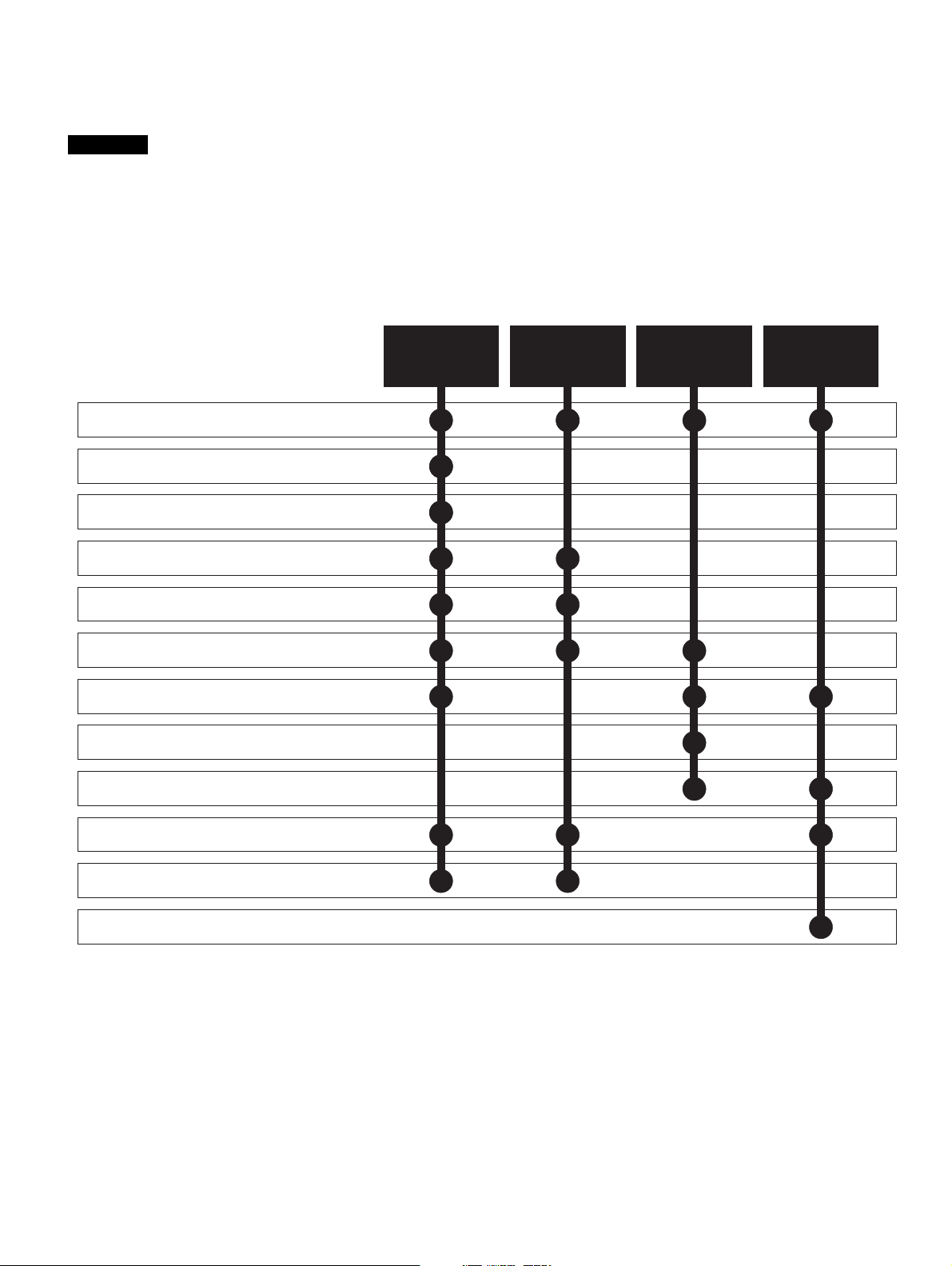
2.4 Power flow
The following phasor diagram illustrates the relationship between the
supply voltage and the Regen drive voltage. The angle between the two
voltage vectors is approximately 5° at full load, this results in a near unity
power factor of 0.996.
Figure 2-1
AC
U
V
W
+DC
-DC
DC
VAC
JLIrω
V
s
V
r
I
r
Supply
jLIrω
V
V
s
r
I
r
Power flow
from supply
V
Supply voltage
s
V Voltage at line terminals of Regen drive
r
j LI Voltage across Regen inductor
ω
r
I Current at line terminals of Regen drive
r
jLIrω
V
r
Power flow
back to supply
I
r
V
s
The direction of the power flow can be changed relative to the supply
voltage, by making small changes to the Regen drives output voltage
and phase.
2.5 Synchronisation
The synchronisation of the Regen drive to the supply does not require
additional hardware. The space vector modulator within the Regen drive
represents the angle and magnitude of the AC supply at all times. This
however is not the case when the AC supply is first connected or when
the Regen drive is disabled.
Unless some form of synchronisation is carried out the current
controllers will start with values of zero resulting in zero volts being
applied to the inverter output terminals. The phase locked loop (PLL)
would also start with zero and so would not lock onto the supply.
To overcome these problems the following information must be obtained
before the Regen drive attempts to start:
1. The mains supply voltage vector magnitude
2. The angle of the supply voltage vector
3. The frequency of the supply
These values are obtained by carrying out a synchronisation on enable
• The first stage of the pre-start tests is to measure the initial DC Bus
voltage, which is assumed to be equal to the peak line-to-line
voltage of the supply.
• The second stage of the pre-start test is to apply two short pulses of
zero volts at the converter input. These pulses must be short enough
so that the peak current is less than the over current trip level of the
converter. The time between the pulses must also be long enough
so that the current built up in the input inductors during the first pulse
has decayed to a low level before the second pulse is applied.
These are used to calculate the instantaneous angle of the supply
voltage vector during the first test pulse. The second test pulse is
Getting
started
Optimisation Parameters
Te ch n ic al
data
Component
sizing
Diagnostics
then applied at time Td later to allow the supply frequency to be
calculated.
At this stage the supply inductance is also calculated
• Once the synchronization is complete the phase locked loop (PLL) is
set-up. At this point the whole control system could be started and
should operate without any large transients.
• To improve the robustness of the start-up phase a further short test
pulse voltage vector, with the same magnitude and phase as the
estimated supply voltage vector is applied. This is to detect
measurement errors that could have occurred because of supply
distortion present during the pre-start tests.
2.6 Current trimming
A current feedback trimming routine runs before the drive is enabled to
minimise offsets in the current feedback. This feature can be user
configured, for more details refer to section 8.5 Current trimming on
page 91.
2.7 Regen system configurations
The Regen drive has been designed to provide a regulated DC supply to
other motoring drives. The Regen drive gives bi-directional power flow
with sinusoidal currents and a near unity power factor.
Following are the possible configurations for Unidrive SP Regen:
• Single Regen, single or multiple motoring (Figure 4-1 on page 32)
• Single Regen, multiple motoring using a Unidrive SPMC (Figure 42 on page 34)
• Single Regen, multiple motoring using an external charging resistor
(Figure 4-3 on page 36)
• Multiple Regen, multiple motoring using a Unidrive SPMC (Figure 44 on page 38)
Refer to Table 3-2 on page 14, for the Regen drive ratings.
The sizing of a regen system must take into account the following
factors:
• Line voltage
• Motor rated current, rated voltage and power factor
• Maximum load power and overload conditions
In general, when designing a regen system, equal Regen and motoring
drive rated currents will work correctly. However, care must be taken to
ensure that under worst case supply conditions the Regen drive is able
to supply or absorb all the required power. In multi-drive configurations,
the Regen drive must be of a sufficient size to supply the net peak power
demanded by the combined load of all the motoring drives and total
system losses.
If the Regen drive is unable to supply the full power required by the
motoring drive, the DC bus voltage will drop and in severe cases may
lose synchronisation with the mains and trip. If the Regen drive is unable
to regenerate the full power from the motoring drive on the DC bus, then
the Regen and motoring drive(s) will trip on over-voltage.
8 Unidrive SP Regen Installation Guide
www.controltechniques.com Issue Number: 2
Safety
Information
Introduction
Product
information
System
design
Mechanical
installation
Electrical
installation
Getting
started
Optimisation Parameters
Technical
data
Component
sizing
Diagnostics
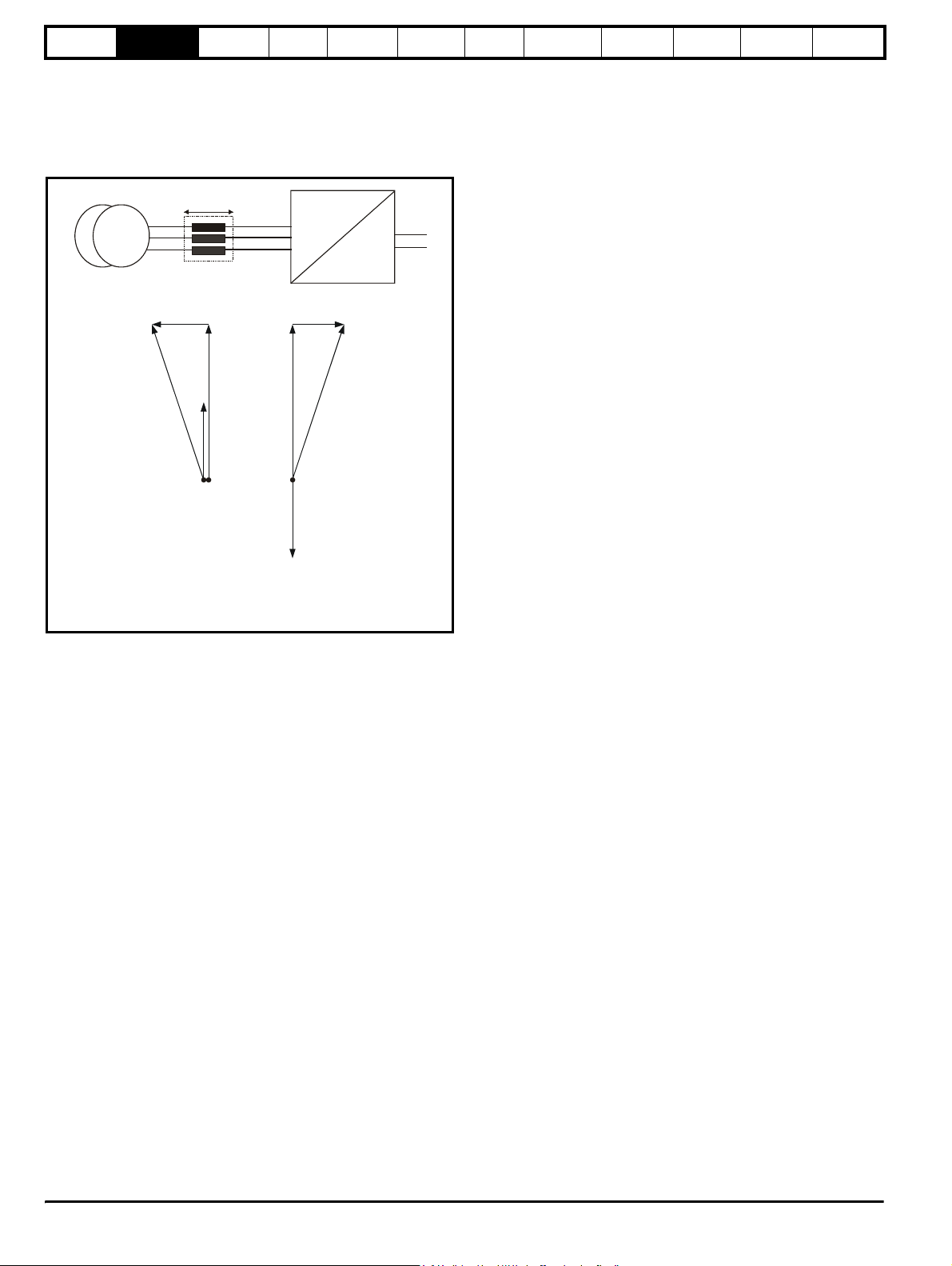
2.8 Regen drive system types
2.8.1 Single Regen, single motoring system
Figure 2-2 shows a typical layout for a standard regen system consisting of a single Regen drive and single motoring drive. In this configuration the
Regen drive is supplying the motoring drive and passing the regenerative energy back to the mains supply.
NOTE
The power up connections to L1, L2, L3 of the Regen drive are only made during power-up. Once both drives are powered up, this is switched out
and the main regen supply switched in. The auxiliary on the charging circuit to the Regen drive’s L1, L2, L3 connections for power up must be closed
(charging supply removed) before the Regen drive can be enabled.
Figure 2-2 Single Regen, single motoring system
Regen
inductor
L1
L2
Additional
circuitry
L3
U
Regen drive
U
AC supply
V
connection
W
L1
+DC
-DC
L2 L3
Common
DC bus
connections
U
Motoring drive
+DC
-DC
Motor
Connection
U
V
W
Power up only
NOTE
For the above single Regen, single motoring configuration; the Regen drive must be of the same frame size or larger.
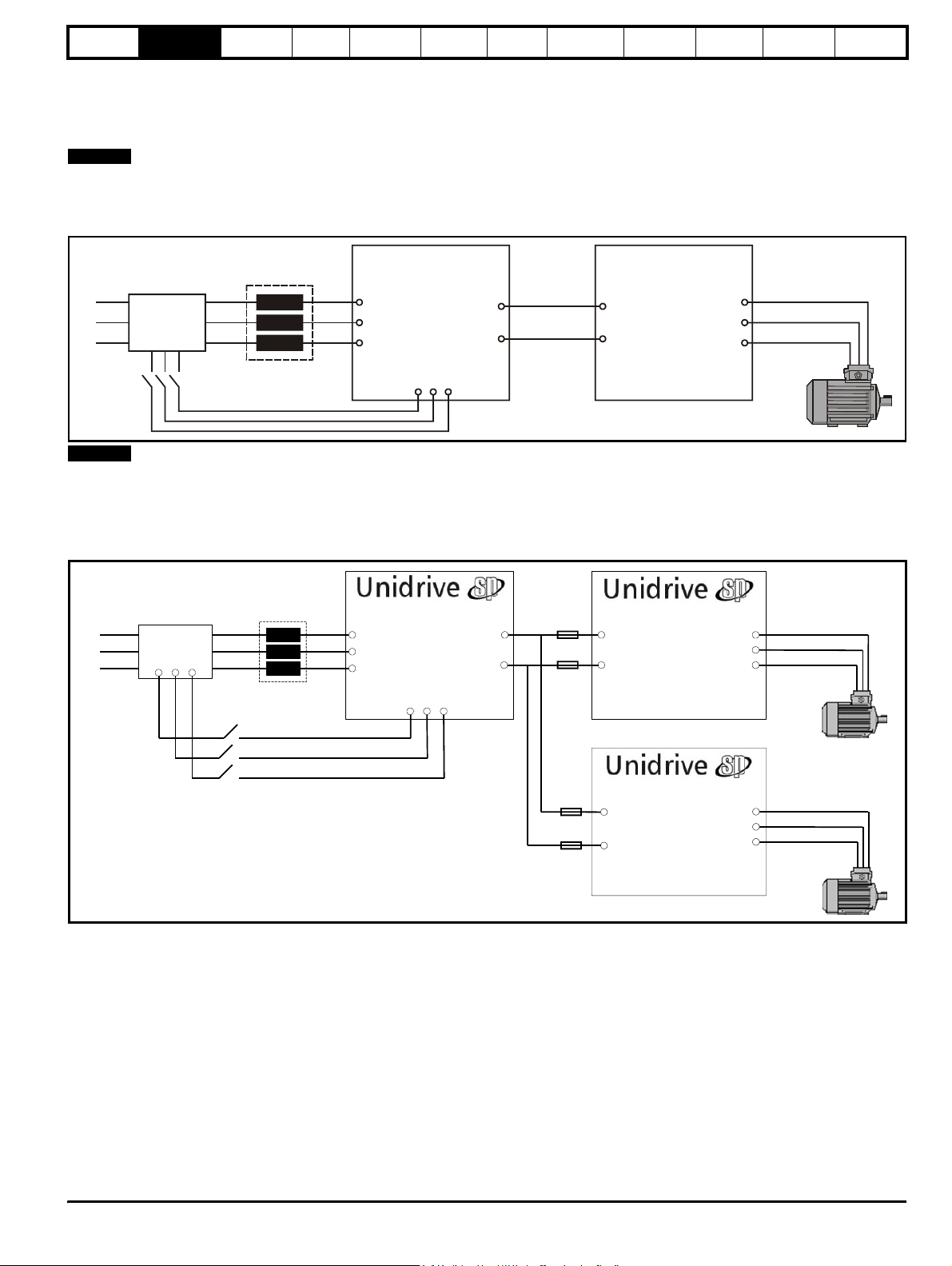
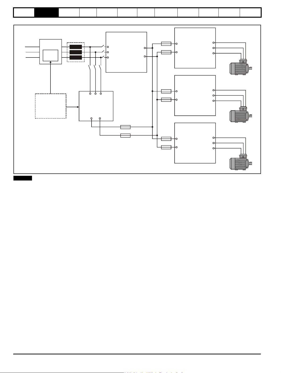
2.8.2 Single Regen, multiple motoring system
Figure 2-4 shows the layout for a regen system consisting of a single Regen drive with multiple motoring drives. In this configuration the Regen drive
is sized to the total power of all motoring drives.
Figure 2-3 Single Regen, multiple motoring system
Regen
Inductor
L1
L2
L3
Additional
Circuitry
Regen Drive
U
AC Supply
V
Connection
W
L1
+DC
-DC
L2 L3
DC Bus
Connections
Motoring Drive
+DC
-DC
Connection
Motor
U
V
W
Power up only
Motoring Drive
+DC
Connection
-DC
Motor
U
V
W
It is also possible to have a single Regen drive powering multiple motoring drives as shown with the power up connections also being provided via the
Regen drives L1, L2, L3 inputs and using the Regen drives own internal softstart.
In this arrangement the total capacitance of the motoring drives must not exceed the capacitance of the Regen drive, in cases where this does please
contact Technical Support.
Unid rive SP Regen Insta llation G uide 9
Issue Number: 2 www.controltechniques.com
Safety
Information
Introduction
Product
information
System
design
Mechanical
installation
Figure 2-4 Single Regen, multiple motoring system
Electrical
installation
Getting
started
Optimisation Parameters
Te ch n ic al
data
Component
sizing
Diagnostics
Regen
Additional
L1
L2
L3
circuitry
External
charging
circuit
inductor
U
Regen drive
U
AC supply
V
connection
W
+DC
-DC
U
Motoring drive 1
+DC
-DC
connection
Motor
U
V
W
U
Motoring drive 2
Charging circuit can
consist of either
Unidrive SPMC
solution or external
charging circuit as
detailed in Chapter 4
System Design
L1 L2 L3
Unidrive
SPMC
+DC -DC
Common DC Bus
+DC
connection
-DC
connections
Motor
U
V
W
U
Motoring drive 3
+DC
connection
-DC
Motor
U
V
W
NOTE
For a single Regen and multiple motoring drive arrangement optional charging circuits can be used for the increased inrush current generated by the
additional capacitance of the multiple motoring drives. The charging circuit can consist of either a Unidrive SPMC rectifier module or an external
charging resistor as detailed in Chapter 4 System design
10 Unidrive SP Regen Installation Guide
www.controltechniques.com Issue Number: 2
Safety
Information
Introduction
Product
information
System
design
Mechanical
installation
Electrical
installation
Getting
started
Optimisation Parameters
Technical
data
Component
sizing
Diagnostics
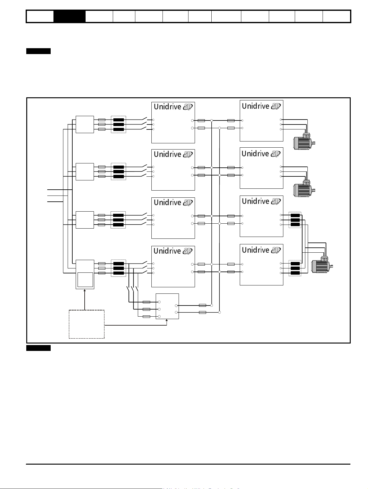
2.8.3 Multiple Regen, multiple motoring system
Figure 2-5 shows a multiple regen drive system with multiple motoring drives. For this configuration the regen drives are sized to the total power
requirement of all motoring drives.
NOTE
For the multiple regen and multiple motoring drives arrangement there are two possible options for the required start-up circuit. This can either consist
of a Unidrive SPMC rectifier module (for example an SPMC 1402 is capable of charging a maximum DC Bus capacitance of 66mF) or an external
charging resistor as detailed in Chapter 4 System design on page 30.
Special care should be taken when designing a multiple regen and multiple motoring drive system ensuring that all the required fusing is in place on
both the common DC Bus connections and the AC supply to all regen drives.
Figure 2-5 Multiple Regen, multiple motoring system
DC Bus
Additional
Circuitry
Regen Drive
U
V
W
+DC
-DC
Connections
Motoring Drive
Motor
Connection
U
V
W
+DC
-DC
Regen Drive
Additional
Circuitry
L1
L2
L3
Additional
Circuitry
Additional
Circuitry
External
charging
circuit
Charging circuit can
consist of either
Unidrive SPMC
solution or external
charging circuit
(Unidrive SPMC
recommended)
U
V
W
Regen Drive
U
V
W
Regen Drive
U
V
W
SPMC
L1
L2
L3
+DC
-DC
+DC
-DC
+DC
-DC
+DC
-DC
Motoring DriveMotoring Drive
+DC
-DC
Motor
Connection
U
V
W
Motoring DriveMotoring DriveMotoring DriveMotoring Drive
Motor
Connection
U
V
W
+DC
-DC
Motoring Drive
Motor
Connection
U
V
W
+DC
-DC
NOTE
All drives paralleled must be of the same frame size, and a derating also
applies as specified in Chapter 3 Product Information on page 12
Unidr ive SP Re gen Inst allatio n Guide 11
Issue Number: 2 www.controltechniques.com
Safety
/
date code
Information
Introduction
Product
information
System
design
Mechanical
installation
Electrical
installation
Getting
started
Optimisation Parameters
3 Product Information
3.1 Model number
The way in which the model numbers for the Unidrive SP range are formed is illustrated below.
Technical
data
Component
sizing
Diagnostics
Unidrive SP product line
SP:
Solutions platform
complete inverter drive
Power module power stages
SPMA:
for custom drive systems AC input
SPMD:
Power module power stages
for custom drive systems DC input
SP frame size
Voltage rating
0:
Voltage independent
2:
200V to 240V
4:
380V to 480V
5:
500V to 575V
6:
500V to 690V
Configuration
Wall mount
0:
Wall mount, no dynamic brake control
2:
Stand alone, no dynamic brake control
3:
Current rating step
SPX
1 4 0 1
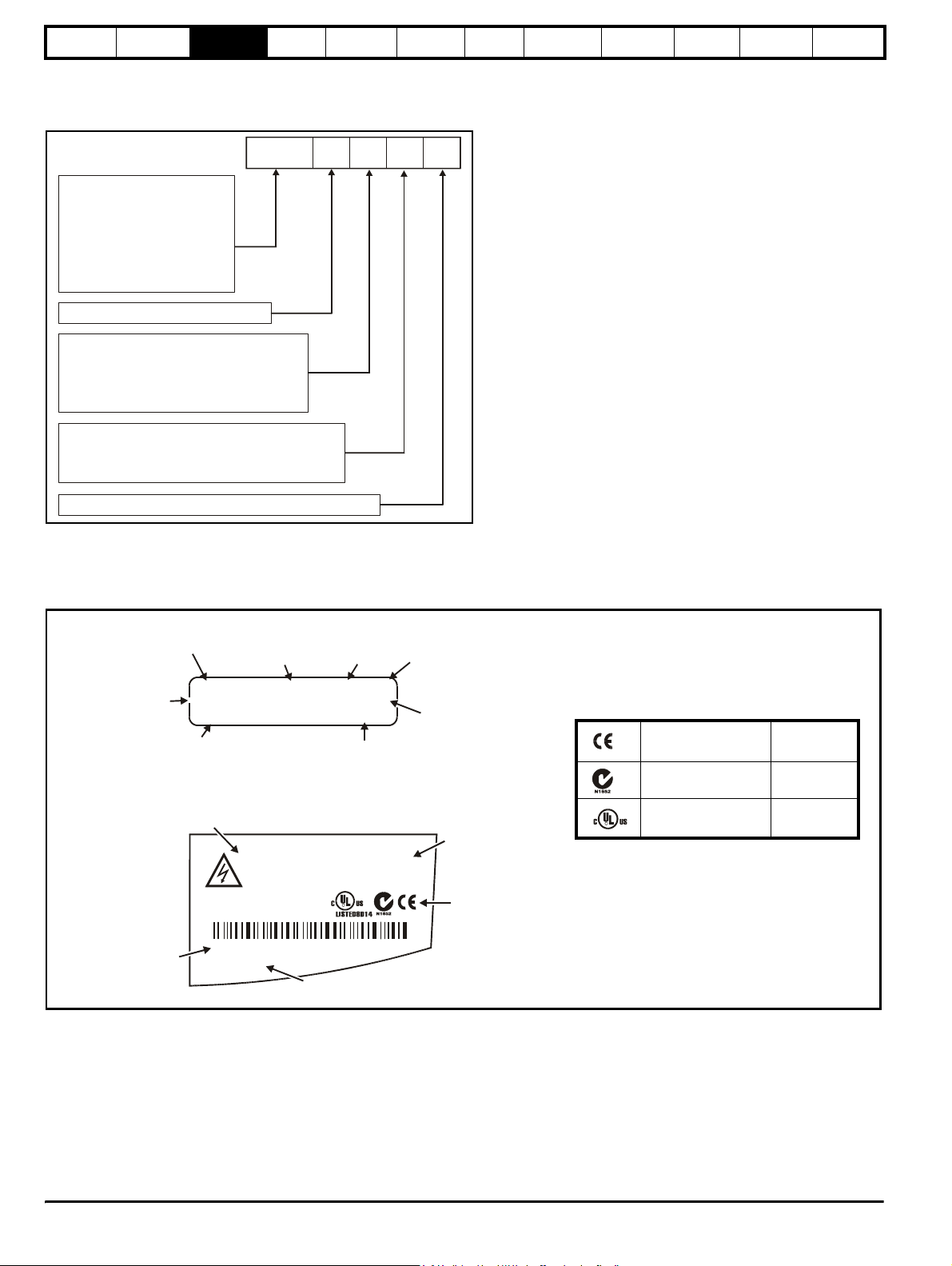
3.2 Nameplate description
See Figure 3-2 on page 17 for location of rating labels.
Figure 3-1 Typical drive rating labels
Rating label
Input voltage
rating
Model
Output voltage
range
Approvals label
I/P 200-240V 50-60Hz 3ph 6.6A
SP1201
O/P 0-240V 4.3 / 5.2A
Model
Please read manual before connecting.
Input
frequency
S.No:
3000005001
SP 1,5 TL
Heavy Duty / Normal Duty
rating output current
SP1201 0.75 / 1.1kW
Electric Shock Risk: Wait 10 min between
disconnecting supply & removing covers
SP 1,5 TL
IND.
CONT.
EQ.
No. of
phases
R
Typical input
current for
Normal Duty
rating
Serial
number
Heavy Duty
Normal Duty
power rating
Approvals
Key to approvals
CE approval Europe
C Tick approval Australia
UL / cUL approval
R
USA &
Canada
Serial
number
3000005001
STDL25
Made In U.K
Ser No:
Customer and
12 Unidrive SP Regen Installation Guide
www.controltechniques.com Issue Number: 2
Safety
Information
Introduction
Product
information
System
design
Mechanical
installation
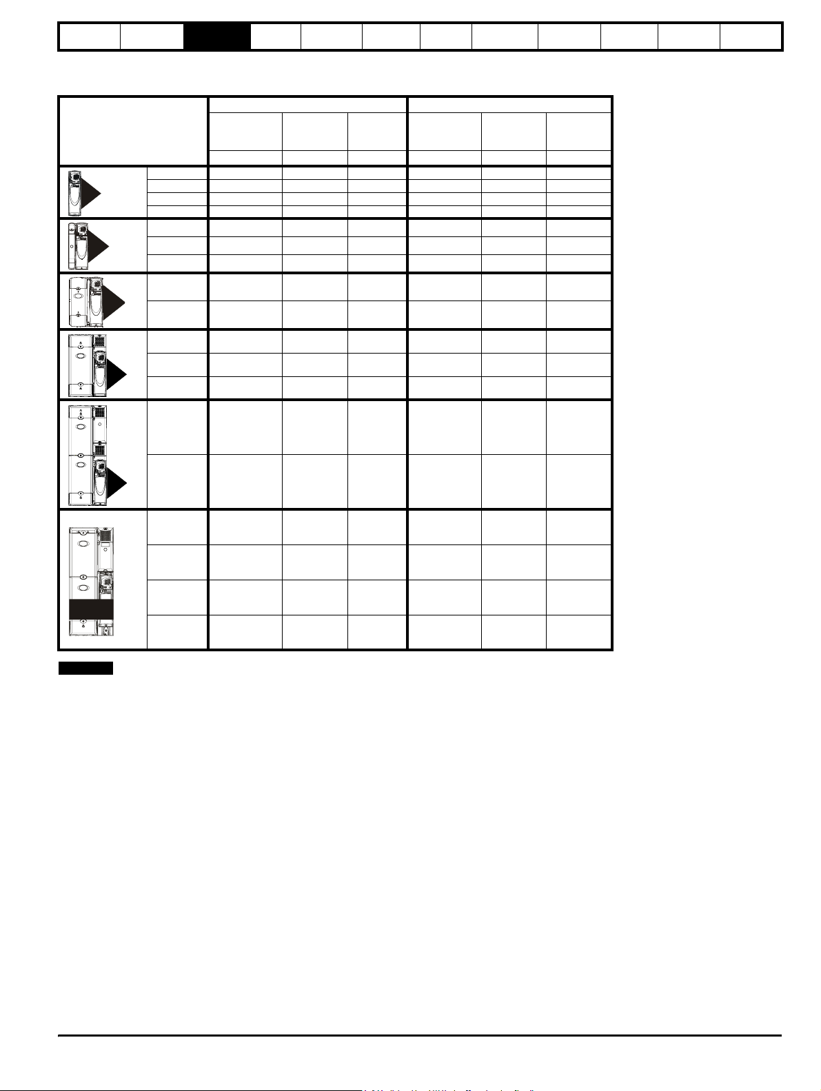
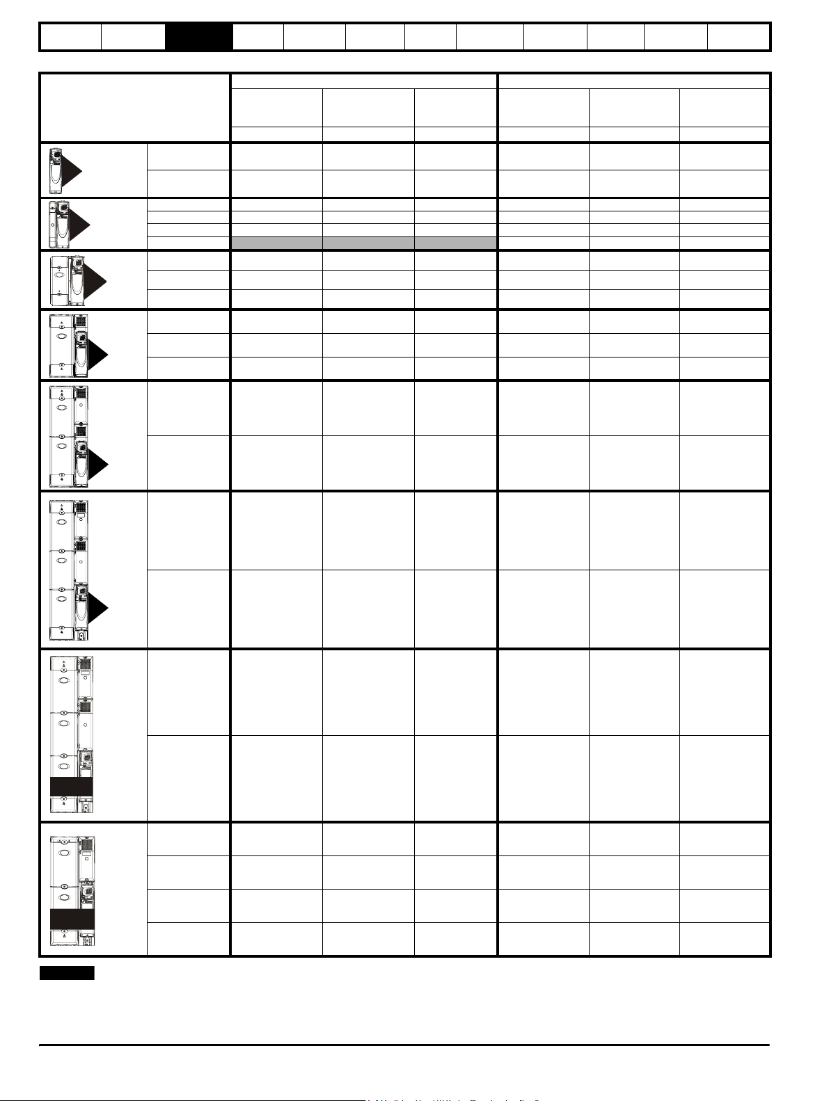
3.3 Ratings
Table 3-1 200V Drive ratings (200V to 240V ±10%)
Normal Duty Heavy Duty
Model
1201 5.2 1.1 1.5 4.3 0.75 1.0
1
2
3
4
1202 6.8 1.5 2.0 5.8 1.1 1.5
1203 9.6 2.2 3.0 7.5 1.5 2.0
1204 11 3.0 3.0 10.6 2.2 3.0
2201 15.5 4.0 5.0 12.6 3.0 3.0
2202 22 5.5 7.5 17 4.0 5.0
2203 28 7.5 10 25 5.5 7.5
3201 42 11 15 31 7.5 10
3202 54 15 20 42 11 15
4201 68 18.5 25 56 15 20
4202 80 22 30 68 18.5 25
4203 104 30 40 80 22 30
5201 130 37 50 105 30 40
Maximum
continuous
output current
AkWhpAkWhp
Nominal
power
at 220V
Electrical
installation
Motor
power
at 230V
Getting
started
Maximum
continuous
output current
Optimisation Parameters
Nominal
power
at 220V
Motor
power
at 230V
Technical
data
Component
sizing
Diagnostics
55
5202 154 45 60 130 37 50
1201 192 55 175 156 45 60
1202 248 75 100 192 55 75
1203 312 90 125 250 75 100
SPMD
1204 350 110 150 290 90 125
NOTE
The above current ratings are given for max 40°C (104°F), and 3.0 kHz
switching. Derating is required for higher switching frequencies, ambient
temperature >40°C (104°F) and high altitude. For further information,
refer to both the Unidrive SP and SPM User Guides.
Unidr ive SP Re gen Inst allatio n Guide 13
Issue Number: 2 www.controltechniques.com
Safety
Information
Introduction
Product
information
System
design
Mechanical
installation
Table 3-2 400V drive ratings (380V to 480V ±10%)
Model
1405 8.8 4.0 5.0 7.6 3.0 5.0
1
2
3
1406 11 5.5 7.5 9.5 4.0 5.0
2401 15.3 7.5 10 13 5.5 10
2402 21 11 15 16.5 7.5 10
2403 29 15 20 25 11 20
2404
3401 35 18.5 25 32 15 25
3402 43 22 30 40 18.5 30
3403 56 30 40 46 22 30
4401 68 37 50 60 30 50
Maximum
continuous
input current
AkWhpAkWhp
Electrical
installation
Normal Duty Heavy Duty
Typical motor
power
at 400V
Getting
started
Typ i cal m o to r
power
at 460V
Optimisation Parameters
Maximum
continuous
input current
29 15 20
Technical
data
Typical motor
power
at 400V
Component
sizing
Diagnostics
Typical motor
power
at 460V
4
55
56
4402 83 45 60 74 37 60
4403 104 55 75 96 45 75
5401 138 75 100 124 55 100
5402 168 90 125 156 75 125
6401 202 110 150 180 90 150
6402 236 132 200 210 110 150
1401 205 110 150 180 90 150
SPMA
1402 236 132 200 210 110 150
1401 205 110 150 180 90 150
1402 246 132 200 210 110 150
1403 290 160 250 246 132 200
SPMD
1404 350 200 300 290 160 250
NOTE
The SPMD1404 can deliver 350A continuously only if the ambient is 35°C or lower and it is docked to the SPMC. Under all other circumstances the current rating is 335A.
The above current ratings are given for max 40°C (104°F), and 3.0 kHz switching. Derating is required for higher switching frequencies, ambient
temperature >40°C (104°F) and high altitude. For further information, refer to both the Unidrive SP and SPM User Guides.
14 Unidrive SP Regen Installation Guide
www.controltechniques.com Issue Number: 2
Safety
Information
Introduction
Product
information
System
design
Mechanical
installation
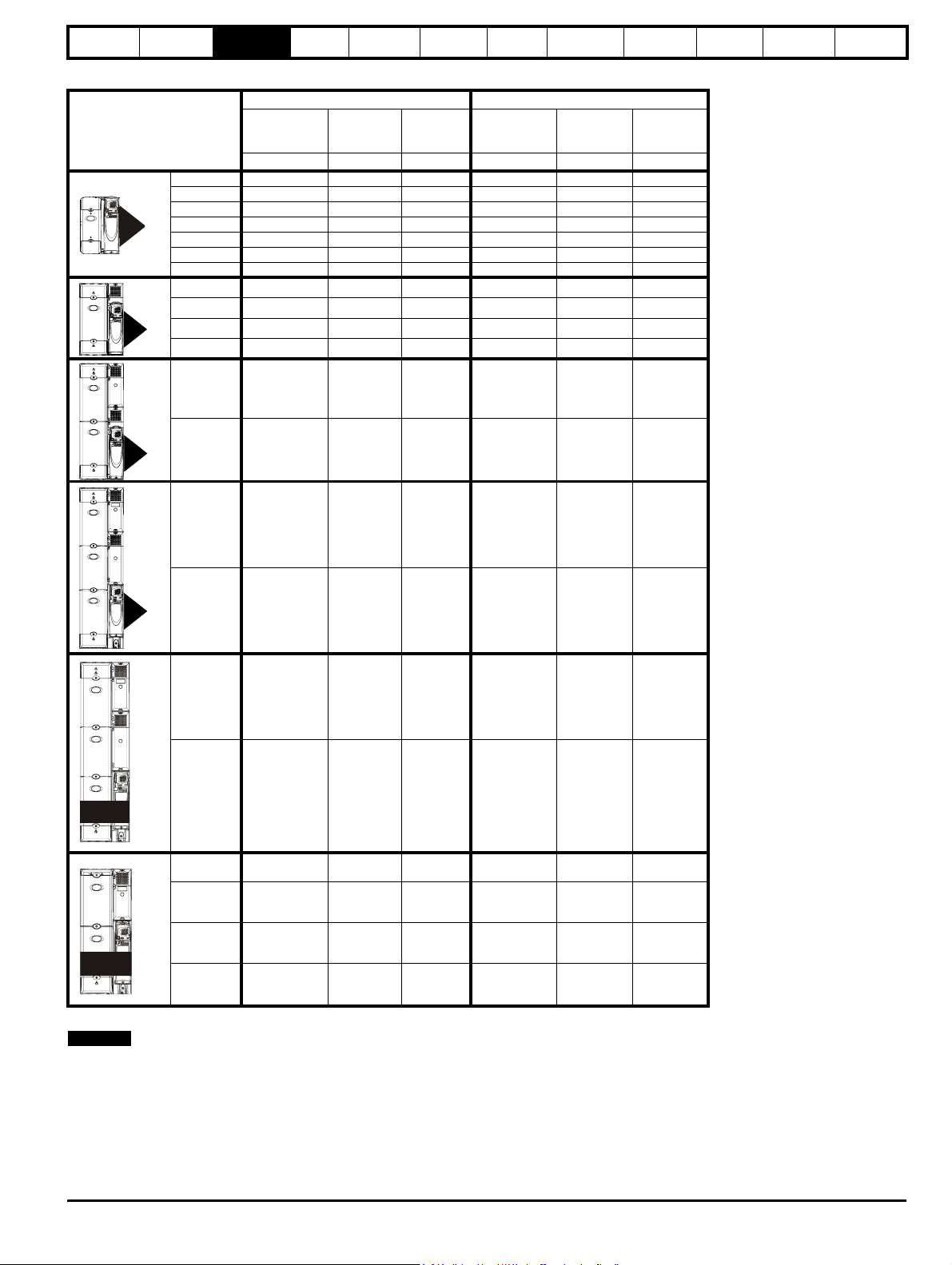
Table 3-3 575V Drive ratings (500V to 575V ±10%)
Normal Duty Heavy Duty
3
4
Model
Maximum
continuous
output current
AkWhpAkWhp
3501 5.4 3.0 3.0 4.1 2.2 2.0
3502 6.1 4.0 5.0 5.4 3.0 3.0
3503 8.4 5.5 7.5 6.1 4.0 5.0
3504 11 7.5 10 9.5 5.5 7.5
3505 16 11 15 12 7.5 10
3506 22 15 20 18 11 15
3507 27 18.5 25 22 15 20
4603 36 22 30 27 18.5 25
4604 43 30 40 36 22 30
4605 52 37 50 43 30 40
4606 62 45 60 52 37 50
5601 84 55 75 63 45 60
Nominal
power
at 575V
Electrical
installation
Motor
power
at 575V
Getting
started
Maximum
continuous
output current
Optimisation Parameters
Nominal
power
at 575V
Motor
power
at 575V
Technical
data
Component
sizing
Diagnostics
SPMA
55
56
5602 99 75 100 85 55 75
6601 125 90 125 100 75 100
6602 144 110 150 125 90 125
1601 125 90 125 100 75 100
1602 144 110 150 125 90 125
1601 125 110 150 100 90 125
1602 144 132 175 125 110 150
1603 168 160 200 144 132 175
SPMD
1604 192 185 250 168 160 200
The power ratings above for model size 4 and larger are for the 690V drives when used on a 500V to 575V supply.
NOTE
The above current ratings are given for max 40°C (104°F), and 3.0 kHz switching. Derating is required for higher switching frequencies, ambient
temperature >40°C (104°F) and high altitude. For further information, refer to both the Unidrive SP and SPM User Guides.
Unidr ive SP Re gen Inst allatio n Guide 15
Issue Number: 2 www.controltechniques.com

Safety
Information
Introduction
Product
information
System
design
Table 3-4 690V Drive ratings (690V ±10%)
Maximum
continuous
output current
AkWhpAkWhp
4
Model
4601 22 18.5 25 19 15 20
4602 27 22 30 22 18.5 25
4603 36 30 40 27 22 30
4604 43 37 50 36 30 40
4605 52 45 60 43 37 50
4606 62 55 75 52 45 60
5601 84 75 100 63 55 75
Mechanical
installation
Normal Duty Heavy Duty
Nominal
power
at 690V
Electrical
installation
Motor
power
at 690V
Getting
started
Maximum
continuous
output current
Optimisation Parameters
Nominal
power
at 690V
Motor
power
at 690V
Technical
data
Component
sizing
Diagnostics
SPMA
55
56
5602 99 90 125 85 75 100
6601 125 110 150 100 90 125
6602 144 132 175 125 110 150
1601 125 110 150 100 90 125
1602 144 132 175 125 110 150
1601 125 110 150 100 90 125
1602 144 132 175 125 110 150
1603 168 160 200 144 132 175
SPMD
1604 192 185 250 168 160 200
NOTE
The above current ratings are given for max 40°C (104°F), and 3.0 kHz switching. Derating is required for higher switching frequencies, ambient
temperature >40°C (104°F) and high altitude. For further information, refer to both the Unidrive SP and SPM User Guides.
16 Unidrive SP Regen Installation Guide
www.controltechniques.com Issue Number: 2
Safety
A
±
r
A
Information
Introduction
Product
information
System
design
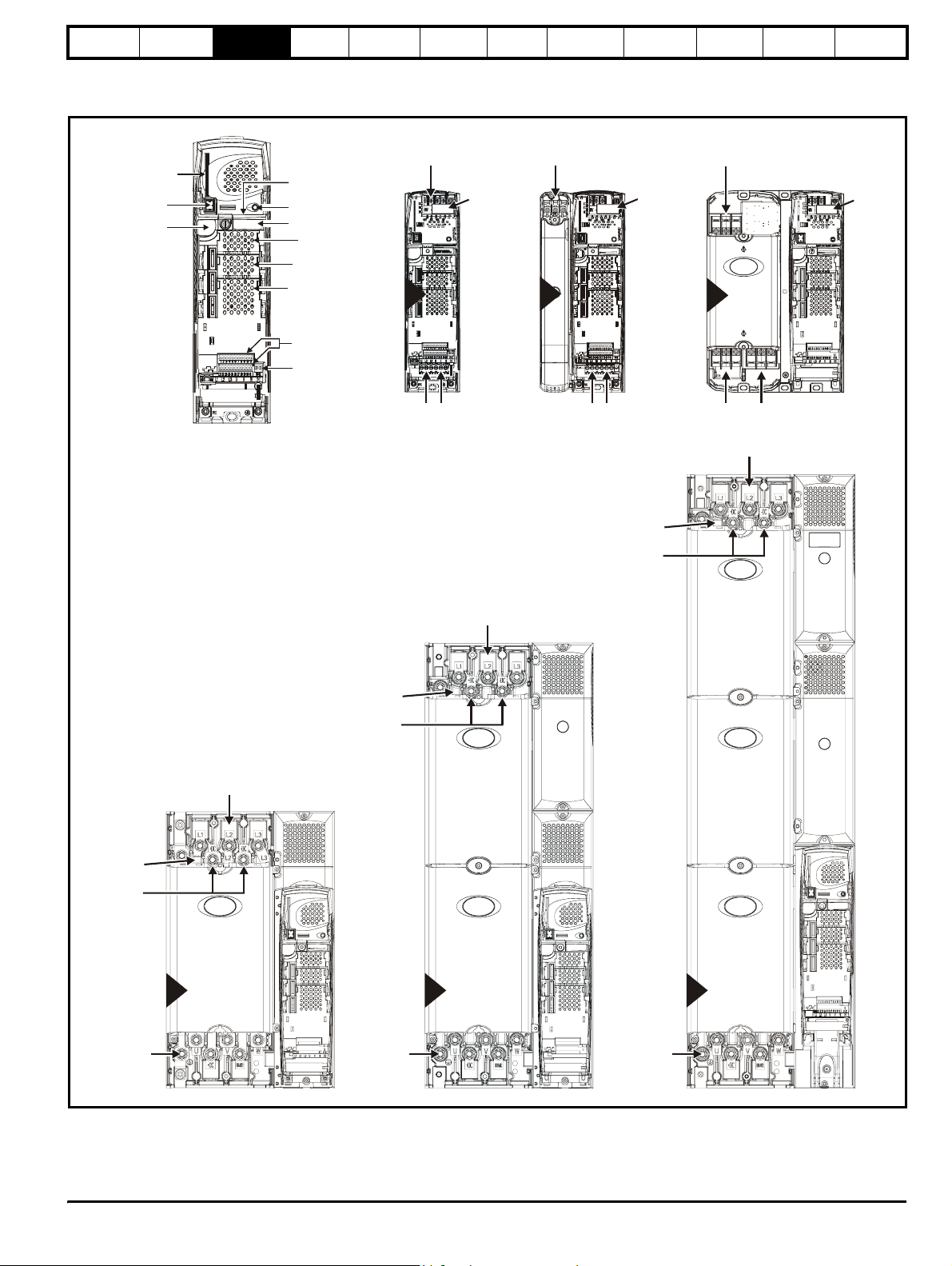
3.4 Drive features
Figure 3-2 Features of the drive sizes 1 to 6
SMARTCARD
slot
Keypad
connection
Serial port
connector
Approvals label
Status LED
Rating label
Solutions Module
slot 1
Solutions Module
slot 2
Solutions Module
slot 3
Mechanical
installation
±
Electrical
installation
DC Bus output
(High current)
1
EMC
capacitor
must be
removed
Getting
started
Optimisation Parameters
DC Bus output
(High current)
2
EMC
capacitor
must be
removed
Technical
data
±
DC Bus output
(High current)
3
3
Component
sizing
Diagnostics
EMC
capacito
must be
removed
Charging input
(L1, L2, L3)
Control terminals
Relay terminals
EMC capacitor
±
DC Bus output
(High current)
Charging input
(L1, L2, L3)
must be
removed
AC supply
(U, V, W)
Charging input
(L1, L2, L3)
Charging input
(L1, L2, L3)
AC supply
(U, V, W)
EMC capacitor
must be
removed
±
DC Bus output
(High current)
Charging input
(L1, L2, L3)
(U, V, W)
Charging input
(L1, L2, L3)
C supply
EMC capacitor
must be
removed
±
DC Bus output
(High current)
AC supply
(U, V, W)
4
AC supply
(U, V, W)
5
C supply
(U, V, W)
6
Unidr ive SP Re gen Inst allatio n Guide 17
Issue Number: 2 www.controltechniques.com
Safety
y
Information
Introduction
Product
information
System
design
Mechanical
installation
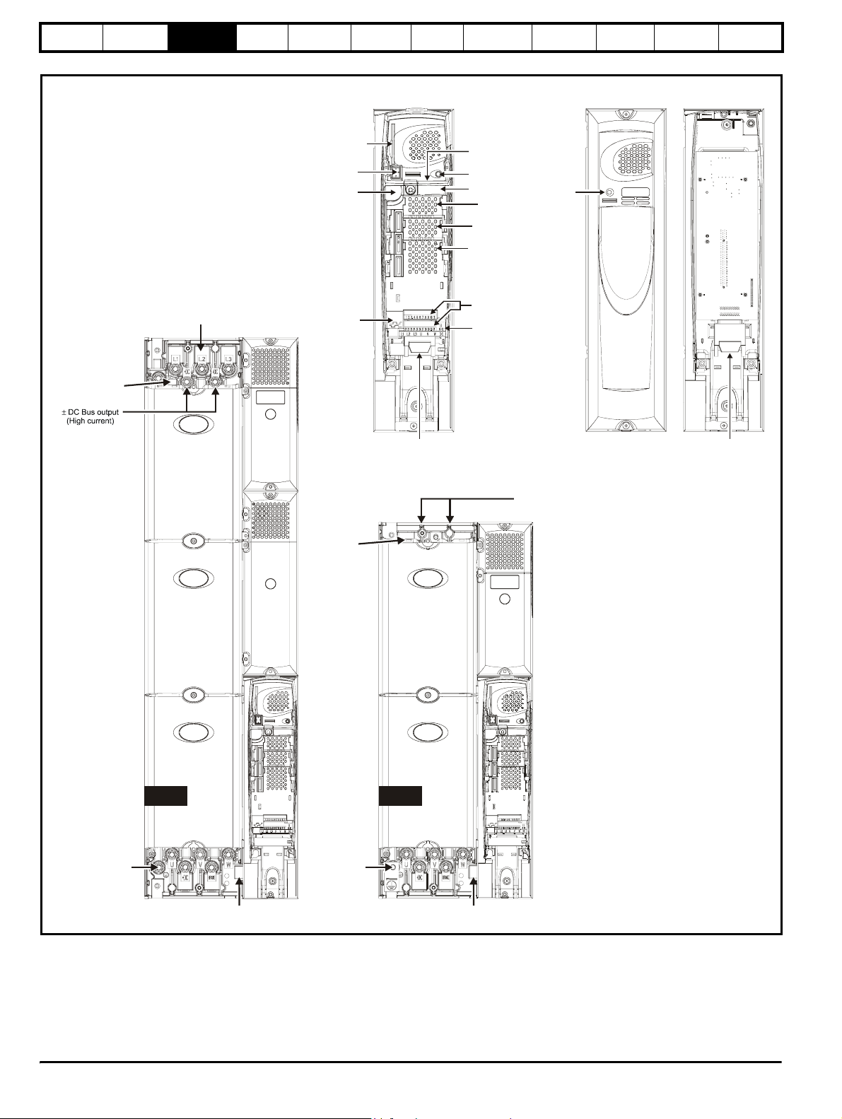
Figure 3-3 Features of the drive sizes SPMA and SPMD
SMARTCARD
slot
Keypad
connection
Serial port
connector
Electrical
installation
Getting
started
Optimisation Parameters
Technical
data
Master interface Slave interface
Cover Base
Approvals label B
Status LED
Rating label
Solutions Module
slot 1
Solutions Module
slot 2
Solutions Module
slot 3
Stat us
LED
Component
sizing
Diagnostics
EMC capacitor
must be removed
Charging input
(L1, L2, L3)
Encoder
connection
EMC capacitor
must be removed
Output connections
to slave
Control terminals
Relay terminals
±
(high current)
DC Bus output
Input from Master /
Output to slave
SPMA SPMD
AC supply
(U, V, W)
Heatsink fan
supply connections
AC supply
(U, V, W)
Heatsink fan
suppl
connections
18 Unidrive SP Regen Installation Guide
www.controltechniques.com Issue Number: 2
Safety
Information
Introduction
Product
information
System
design
Mechanical
installation
Electrical
installation
Getting
started
Optimisation Parameters
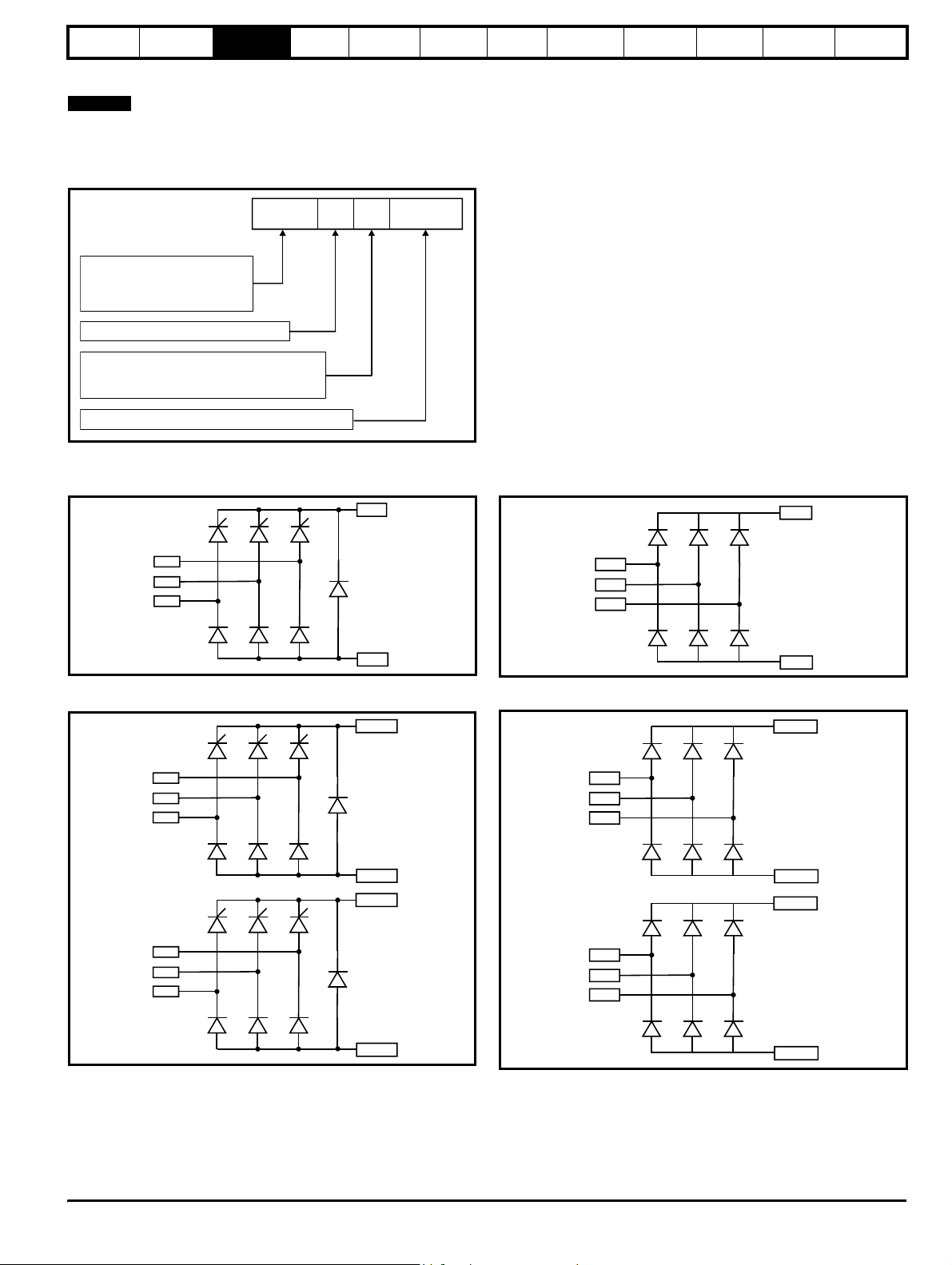
3.5 Unidrive SPMC half controlled thyristor rectifier
NOTE
For the 200V modules where an external charging circuit is required the
SPMU1401, SPMU1402 and SPMU2402 can be used as detailed
following:
Figure 3-4 Rectifier (SPMC and SPMU)
SPMC 1 402
Unidrive SPM product line
Controlled rectifier
SPMC:
SPMU:
Uncontrolled rectifier
Number of rectifier stages
Vol tag e rat i ng
4: 380V to 480V
6: 500V to 690V
Current rating step
The Unidrive SPMC is a controlled thyristor rectifier and the SPMU is an uncontrolled rectifier.
SPMC1402 and 1601
Figure 3-5 Single half controlled thyristor
+DC
SPMU1401, 1402 and 1601
Figure 3-7 Single diode rectifier
Technical
data
Component
sizing
+DC
Diagnostics
L1
L2
L3
SPMC2402 and 2601
Figure 3-6 Dual half controlled thyristor
L1A
L2A
L3A
L1B
L2B
L3B
-DC
+DC (A)
-DC (A)
+DC (B)
L1
L2
L3
-DC
SPMU2402 and 2601
Figure 3-8 Dual diode rectifier
+DC (A)
L1A
L2A
L3A
-DC (A)
+DC (B)
L1B
L2B
L3B
-DC(B)
-DC (B)
The Unidrive SPMC is a half controlled thyristor bridge is used as a front end to the SPMD inverter module or as a stand alone rectifier for several
smaller drives. Soft-start is built in.
The Unidrive SPMU is used as a front end to the SPMD inverter module or as a stand alone rectifier for several smaller drives. Softstart must be
supplied externally using a resistor and contactor or SPMC.
An external 24V, 3A power supply is required in addition to the AC supply to allow the rectifier to operate. Control wiring is required between the
rectifier and motoring drive(s) so that if the rectifier indicates a fault the motoring drive(s) will be disabled.
Unidr ive SP Re gen Inst allatio n Guide 19
Issue Number: 2 www.controltechniques.com

Safety
Information
Introduction
Product
information
System
design
Mechanical
installation
Electrical
installation
Getting
started
Optimisation Parameters
Technical
data
Component
sizing
Diagnostics
The 24V supply must be protected using a 4A slow-blow fuse, one for each supply pole.
Control connections to the Unidrive SPMC/U should be made with 0.5mm2 cable.
The status relay contacts are rated for switching non-inductive loads at 250Vac 6A non-inductive, up to 4Adc if the voltage is limited to 40V or up to
400mA dc if the voltage is limited to 250Vdc. Protection from overcurrent must be provided.
Figure 3-9 SPMC/U rating label
Input voltage, frequency,
no. of phases and current
Approvals
Serial
number
STDN39
Customer and
date code
Status1 Status0
Status
LEDs
I/P 380-480V 50-60Hz 3ph 204A
O/P 513-648V 552A
Output voltage
and current
Model:
SPMC = Controlled
SPMU = Uncontrolled
SPMC1402
Number of
rectifier
stages
Ser No: 3000005001
Voltage
rating:
4 - 400V
6 - 690V
Indicates
sub-rating
within frame
size
3.6 Unidrive SPMC/U technical data
Table 3-5 Unidrive SPMC / U input current, fuse and cable ratings
Semi-conductor fuse
in series with HRC fuse
HRC IEC
class gG UL
class J
Semi-
conductor
IEC class aR
mm
Model
Typical input
current
A
Maximum
input current
A
Typical DC
current
Adc
SPMC1402 339 344 379 540 400 2 x 120 2 x 4/0 2 x 120 2 x 4/0
SPMC2402 2 x 308 2 x 312 2 x 345 450 400 2 x 120 2 x 4/0 2 x 120 2 x 4/0
SPMU1401 207 210 222 250 315 2 x 70 2 x 2/0 2 x 70 2 x 2/0
SPMU1402 339 344 379 540 400 2 x 120 2 x 4/0 2 x 120 2 x 4/0
SPMU2402 2 x 339 609 2 x 379 450 400 2 x 120 2 x 4/0 2 x 120 2 x 4/0
SPMC1601 192 195 209 250 250 2 x 70 2 x 2/0 2 x 120 2 x 4/0
SPMC2601 2 x 170 2 x 173 2 x 185 250 250 2 x 70 2 x 2/0 2 x 120 2 x 4/0
SPMU1601 192 195 209 250 250 2 x 70 2 x 2/0 2 x 120 2 x 4/0
SPMU2601 2 x 170 2 x 173 2 x 185 250 250 2 x 70 2 x 2/0 2 x 120 2 x 4/0
Cable sizes
AC input DC output
2
AWG
mm
2
AWG
The user must provide a means of preventing live parts from
being touched. A cover around the electrical connections at
the top of the inverter and the bottom of the rectifier where the
WARNING
cables enter is required.
Input fuses as specified must be provided.
WARNING
The Unidrive SPMC/U depends on the drive for protection.
Status outputs must be linked to the drive enable regen
drive(s) and circuit to ensure that when the rectifier indicates
WARNING
a fault the motoring drive(s) are disabled.
20 Unidrive SP Regen Installation Guide
www.controltechniques.com Issue Number: 2
Safety
Information
Introduction
Product
information
System
design
Mechanical
installation
Electrical
installation
Getting
started
Optimisation Parameters
Technical
data
Component
sizing
Diagnostics
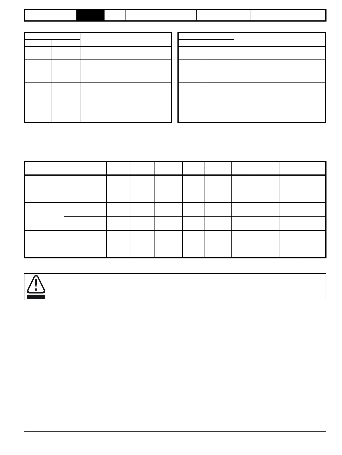
Table 3-6 Key to Unidrive SPMC (rectifier) LEDs Table 3-7 Key to Unidrive SPMU (rectifier) LEDs
Status Output
1: Left LED
OFF OFF
0: Right LED
Definition
Mains loss or 24V supply to the rectifier has
been lost
Status Output
1: Left LED
0: Right LED
Definition
OFF OFF 24V supply to the rectifier has been lost
Any of the following:
OFF ON Phase loss OFF ON
• Internal fault
• Check that rectifier is an SPMU. This
could indicate that unit is an SPMC
Any of the following:
Any of the following:
• Rectifier heatsink over temperature
• Rectifier PCB over temperature
• Status input wire break
ON OFF
• Snubber overheating due to excessive
cable charging current or supply notching
• Rectifier heatsink over temperature
• Rectifier PCB over temperature
ON OFF
• Status input wire break
ON ON System healthy ON ON System healthy
The half controlled thyristor rectifier can be used as an external charging module for a regen system consisting of multiple drives. The required
softstart function is built into the SPMC module as standard. An external 24V, 3A power supply is required in addition to the AC supply for the SPMC
to allow the rectifier to operate. Control wiring is required between the rectifier and drive(s) so that if the rectifier indicates a fault all drive(s) will be
disabled.
Table 3-8 SPM rectifier charging data
Model
AC line current
(100% Normal Duty Motor Current)
DC link current
(100% Normal Duty Motor Current)
Maximum
DC bus
capacitance on
a supply <25kA
Maximum
DC bus
capacitance on
a supply <25kA
Max capacitance
(mF)
When used with
line reactor
Max capacitance
(mF)
When used with
line reactor
SPMU
1401
207 339 677 339 677 192 385 192 385
222 379 758 379 758 209 418 209 418
44 66 132 66 132 29.3 59 29.3 59
INL401 INL402 2 x INL402 INL402 2 x INL402 INL602 2 x INL602 INL602 2 x INL602
44 66 66 66 66 29.3 29.3 29.3 29.3
INL401 INL402 INL412 INL402 INL412 INL602 INL612 INL602 INL612
SPMU
1402
SPMU
2402
SPMC
1402
SPMC
2402
SPMU
1601
SPMU
2601
SPMC
1601
SPMC
2601
Also refer to the Unidrive SPM User Guide for further detailed information on the Unidrive SPMC mechanical and electrical installation.
• The user must provide a means of preventing live parts from being touched. A cover around the electrical connections at the top of
the inverter and the bottom of the rectifier where the cables enter is required.
WARNING
• Fusing as specified must be provided.
Unidr ive SP Re gen Inst allatio n Guide 21
Issue Number: 2 www.controltechniques.com
Safety
Information
Introduction
Product
information
System
design
Mechanical
installation
Electrical
installation
Getting
started
Optimisation Parameters
Technical
data
Component
sizing
Diagnostics
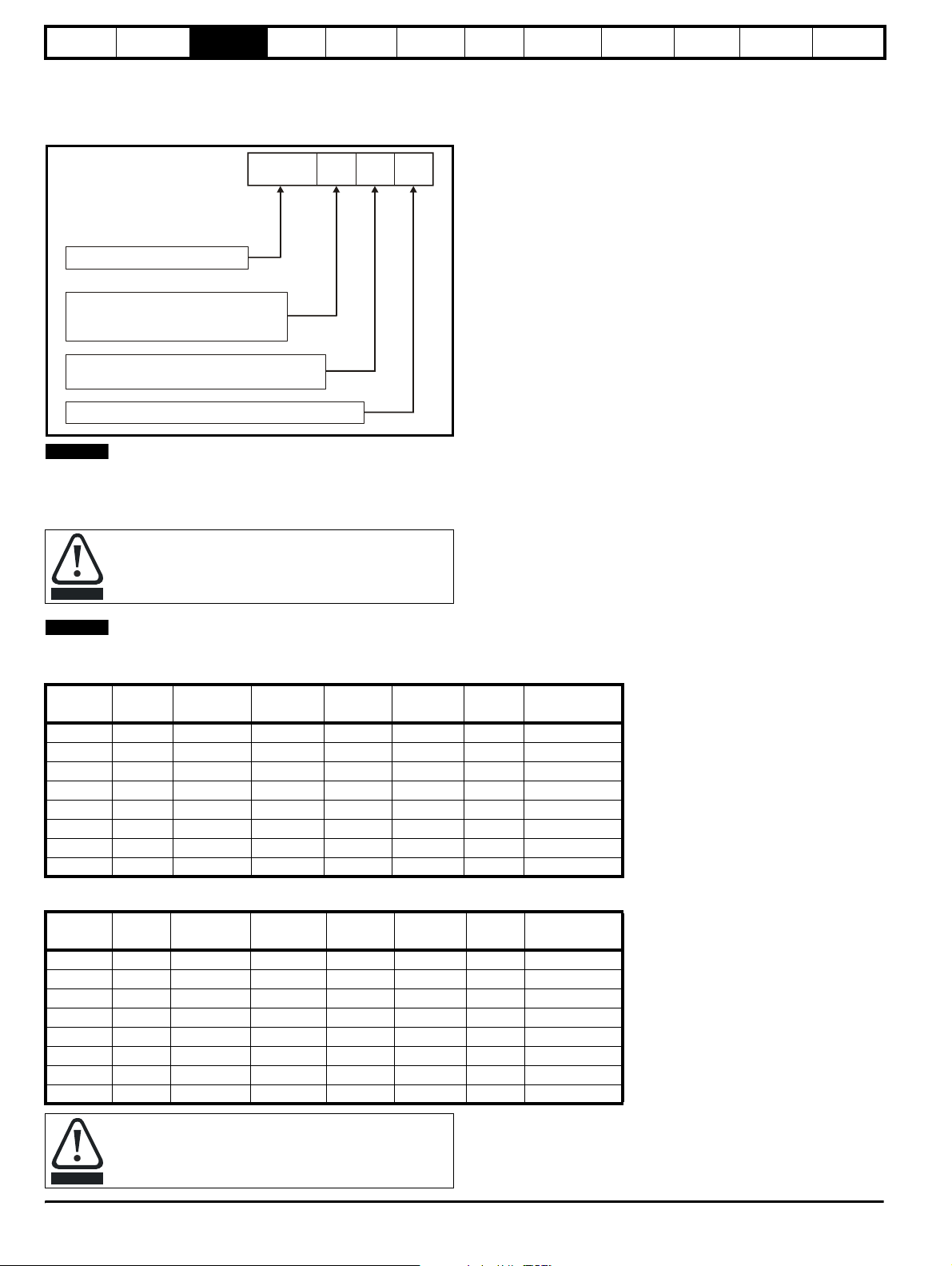
3.7 Output Sharing Chokes (for motoring drives only)
The following section covers the output sharing chokes which are currently available for Unidrive SP. These being used for the motoring drives in a
regen system only (between drive and motor).
Figure 3-10 Output sharing choke identification
OTL:
Output sharing choke
Voltage rating
4: 380V to 480V
6: 500V to 690V
0: Single
1: Dual
Current rating step
NOTE
OTL
4 0 1
For the 200V SPMx modules used in parallel configurations and where output sharing chokes are required the 400V OTL output sharing chokes
should be used.
The following tables detail the output chokes required for the various configurations of paralleled SPMA and SPMD power modules.
When connecting either SPMA or SPMD drives in parallel
they must be de-rated by 5%
CAUTION
NOTE
In order to achieve the best possible current sharing between paralleled Unidrive SPM modules, sharing chokes must be fitted.
Table 3-9 400 / 600V output sharing choke ratings
Model
CurrentAInductanceµHWidth (W)mmDepth (D)mmHeight (H)mmWeight
kg
Part No.
OTL401 221 40.1 240 220 210 20 4401-0197-00
OTL402 267 34 242 220 205 20 4401-0198-00
OTL403 313 28.5 242 220 205 25 4401-0199-00
OTL404 378 23.9 242 220 205 25 4401-0200-00
OTL601 135 103.9 242 170 203 20 4401-0201-00
OTL602 156 81.8 242 170 203 20 4401-0202-00
OTL603 181 70.1 242 200 203 20 4401-0203-00
OTL604 207 59.2 242 200 203 20 4401-0204-00
Table 3-10 400 / 600V centre tapped output sharing choke ratings
Model
CurrentAInductanceµHWidth (W)mmDepth (D)mmHeight (H)mmWeight
kg
Part No.
OTL411 389.5 42.8 300 150 160 8 4401-0188-00
OTL412 470.3 36.7 300 150 160 8 4401-0189-00
OTL413 551 31.1 300 150 160 8 4401-0192-00
OTL414 665 26.6 300 150 160 9 4401-0186-00
OTL611 237.5 110.4 300 150 160 8 4401-0193-00
OTL612 273.6 88.4 300 150 160 8 4401-0194-00
OTL613 319.2 76.7 300 150 160 8 4401-0195-00
OTL614 364.8 65.7 300 150 160 8 4401-0196-00
The OTLX1X centre tapped output sharing chokes can only
be used when two Unidrive SPM drives are paralleled
together. For all other combinations the OTLX0X output
CAUTION
sharing choke must be used.
22 Unidrive SP Regen Installation Guide
www.controltechniques.com Issue Number: 2

Safety
Information
Introduction
Product
information
System
design
Mechanical
installation
3.8 Options
Figure 3-11 Options available for Unidrive SP Regen
SMARTCARD*
Electrical
installation
Getting
started
Keypad
Optimisation Parameters
Technical
Automation Fieldbus
data
Component
sizing
Diagnostics
External
footprint /
bookcase
CT Comms
cable
EMC filter
* A SMARTCARD is provided with the Unidrive SP as standard. Only one SMARTCARD can be fitted at any one time.
NOTE
Position feedback modules will still function with a drive configured in regen mode, however, this would only be required where the Regen drive is to
be used to provide additional Solutions Module slots for the motoring drive.
Unidr ive SP Re gen Inst allatio n Guide 23
Issue Number: 2 www.controltechniques.com
Safety
Information
Introduction
Product
information
System
design
Mechanical
installation
Electrical
installation
Getting
started
Optimisation Parameters
Technical
data
Component
sizing
Diagnostics
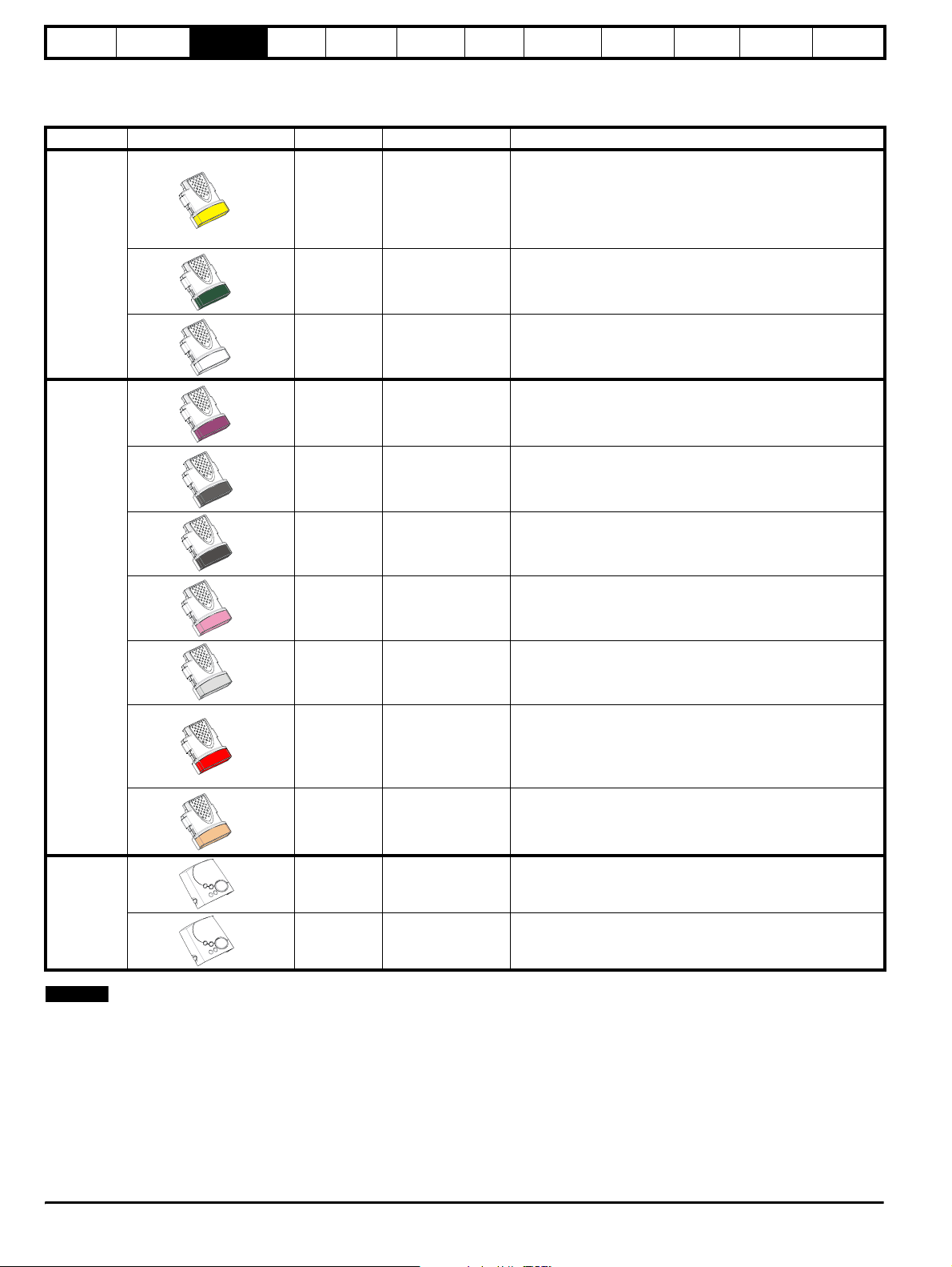
All Unidrive SP Solutions Modules are colour-coded in order to make identification easy. The following table shows the colour-code key and gives
further details on their function.
Table 3-11 Solutions Module identification
Type Solutions Module Colour Name Further Details
Extended I/O interface
Increases the I/O capability by adding the following to the
Yellow SM-I/O Plus
existing I/O in the drive:
• digital inputs x 3
• analogue output (voltage) x 1
• digital I/O x 3 • relay x 2
• analogue inputs (voltage) x 2
Automation
Fieldbus
Dark Green SM-Applications
White SM-Applications Lite
Purple SM-PROFIBUS-DP
Medium Grey SM-DeviceNet
Dark Grey SM-INTERBUS
Pink SM-CAN
Light Grey SM-CANopen
Red SM-SERCOS
Beige SM-Ethernet
Applications Processor (with CTNet)
nd
2
processor for running pre-defined and /or customer created
application software with CTNet support
Applications Processor
nd
2
processor for running pre-defined and /or customer created
application software
Profibus option
PROFIBUS DP adapter for communications with the Unidrive
SP.
DeviceNet option
Devicenet adapter for communications with the Unidrive SP
Interbus option
Interbus adapter for communications with the Unidrive SP
CAN option
CAN adapter for communications with the Unidrive SP
CANopen option
CANopen adapter for communications with the Unidrive SP
SERCOS option
Class B compliant. Torque velocity and position control modes
supported with data rates (bit/sec): 2MB, 4MB, 8MB and 16MB.
Minimum 250µsec network cycle time. Two digital high speed
probe inputs 1µsec for position capture
Ethernet option
10 base-T / 100 base-T; Supports web pages, SMTP mail and
multiple protocols: DHCP IP addressing; Standard RJ45
connection
N/A SM-Keypad
LED keypad option
Keypad with a LED display
Keypad
N/A SM-Keypad Plus
NOTE
Position feedback modules will still function with a drive configured in
LCD keypad option
Keypad with an alpha-numeric LCD display with Help function
regen mode, however, this would only be required where the Regen
drive is to be used to provide additional Solutions Module slots for the
motoring drive.
24 Unidrive SP Regen Installation Guide
www.controltechniques.com Issue Number: 2
Safety
Information
Introduction
Product
information
System
design
Mechanical
installation
Electrical
installation
Getting
started
Optimisation Parameters
Technical
data
Component
sizing
Diagnostics
3.9 Items supplied with the drive
The drive is supplied with a copy of the Unidrive SP Short Form Guide, a
SMARTCARD, the safety booklet, the certificate of quality, an accessory
kit box (see the Unidrive SP User Guide for details) and a CD ROM
containing the following user guides:
• Unidrive SP User Guide (English, French, German, Italian, Spanish)
• Unidrive SP Advanced User Guide
• Unidrive SP Regen Installation Guide
• Solutions Module User Guides
• Unidrive SPM User Guide
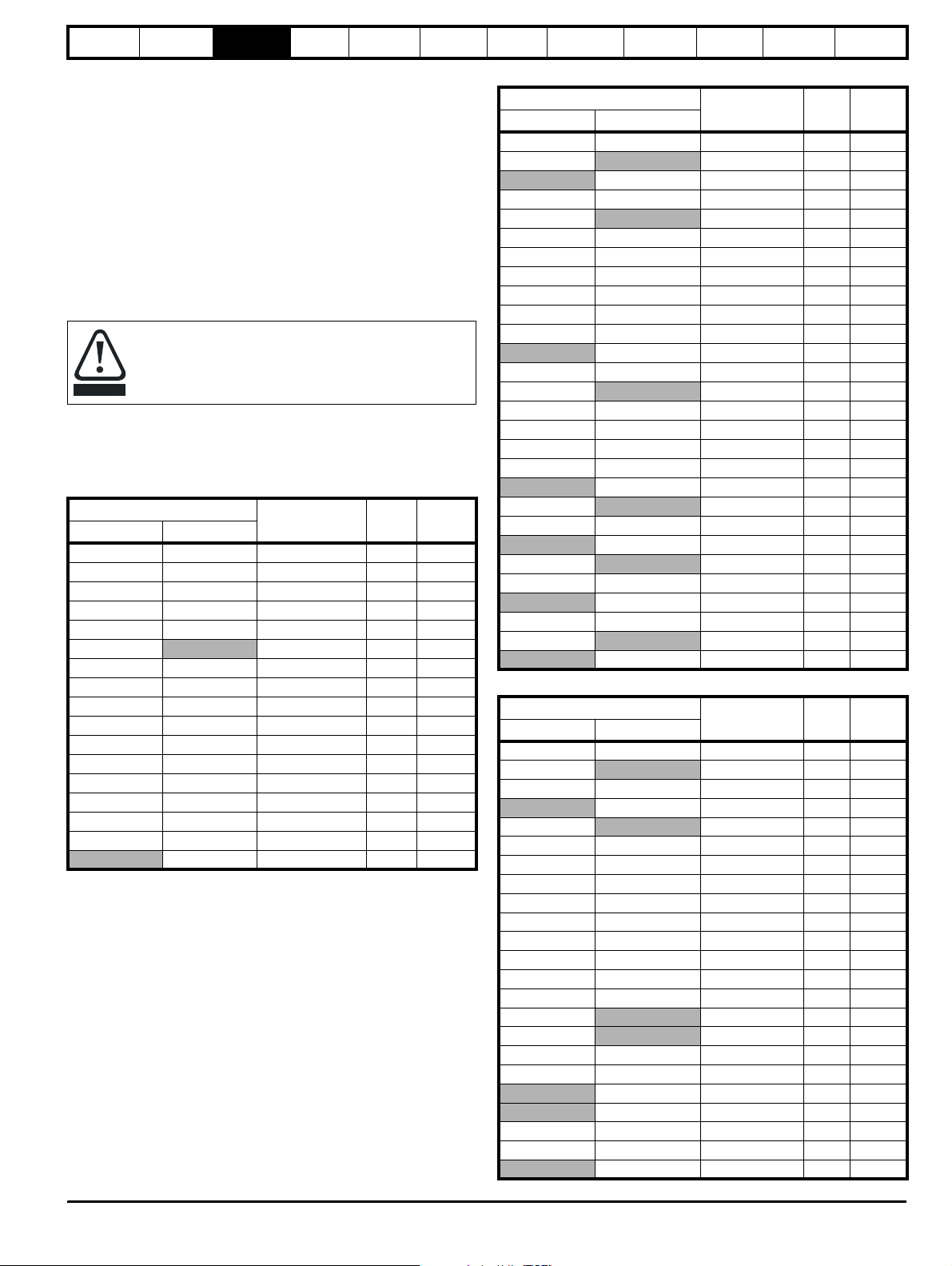
3.10 Regen components
3.10.1 Regen inductor
The following regen inductors are special parts being
designed for very high levels of harmonic voltage and having
a high saturation current with good linearity below saturation.
CAUTION
The regen inductor supports the difference between the PWM voltage
from the Unidrive SP Regen drive and sinusoidal voltage from the
supply.
Table 3-12 200V (200V to 240V ± 10%) Regen Inductors
Heavy Duty Normal Duty
SPMD1201 SP5202 4401-0321 0.22 156.0
SPMD1202 SPMD1201 4401-0322 0.18 192.0
SPMD1203 SPMD1202 4401-0323 0.14 250.0
SPMD1204 SPMD1203 4401-0324 0.11 312.0
Under no circumstances must a part be used other than
those listed.
Drive
Part number mH Arms
SP1203 SP1203 4401-0310 3.50 9.6
SP1204 SP1204 4401-0311 2.70 11.0
SP2201 SP2201 4401-0312 2.20 15.5
SP2202 SP2202 4401-0313 1.60 22.0
SP2203 SP2203 4401-0314 1.10 31.0
SP3201
4401-0314 1.10 31.0
SP3202 SP3201 4401-0315 0.81 42.0
SP4201 SP3202 4401-0316 0.60 56.0
SP4202 SP4201 4401-0317 0.50 68.0
SP4203 SP4202 4401-0318 0.40 80.0
SP5201 SP4203 4401-0319 0.32 105.0
SP5202 SP5201 4401-0320 0.26 130.0
SPMD1204 4401-0325 0.10 350.0
Table 3-13 400V (380V to 480V ± 10%) Regen Inductor
Drive
Heavy Duty Normal Duty
Part number mH Arms
SP1405 SP1405 4401-0001 6.30 9.5
SP1406
4401-0001 6.30 9.5
SP1406 4401-0002 5.00 12.0
SP2401 SP2401 4401-0003 3.75 16.0
SP2402
4401-0003 3.75 16.0
SP2403 SP2402 4401-0004 2.40 25.0
SP2404 SP2403 4401-0005 1.76 34.0
SP3401 SP2404 4401-0005 1.76 34.0
SP3402 SP3401 4401-0006 1.50 40.0
SP3403 SP3402 4401-0007 1.30 46.0
SP4401 SP3403 4401-0008 1.00 60.0
SP4401 4401-0009 0.78 70.0
SP4402 SP4402 4401-0010 0.63 96.0
SP4403
4401-0010 0.63 96.0
SP5401 SP4403 4401-0011 0.48 124.0
SP5402 SP5401 4401-0012 0.38 156.0
SP6401 SP5402 4401-0013 0.33 180.0
SP6402 SP6401 4401-0014 0.30 200.0
SP6402 4401-0015 0.20 300.0
SPMA1401
4401-0013 0.33 180.0
SPMA1402 SPMA1401 4401-0014 0.30 200.0
SPMA1402 4401-0015 0.20 300.0
SPMD1401
4401-0013 0.33 180.0
SPMD1402 SPMD1401 4401-0014 0.30 200.0
SPMD1402 4401-0015 0.20 300.0
SPMD1403 SPMD1403 4401-0015 0.20 300.0
SPMD1404
4401-0015 0.20 300.0
SPMD1404 4401-0205-00 0.16 350.0
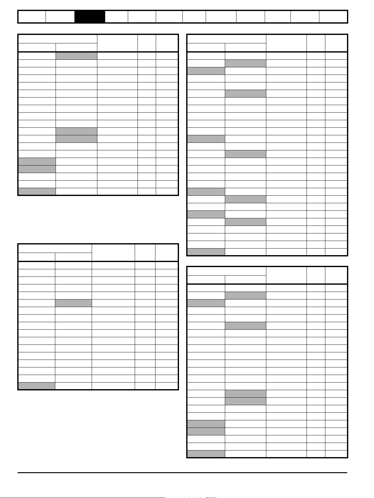
Table 3-14 575V (500V to 575V ± 10%) Regen Inductor
Drive
Heavy Duty Normal Duty
Part number mH Arms
SP3505 SP3505 4401-0210 5.30 19.0
SP3506
4401-0211 4.60 22.0
SP3507 SP3506 4401-0212 3.80 27.0
SP3507 4401-0212 3.80 27.0
SP4601
4401-0211 4.60 22.0
SP4602 SP4601 4401-0212 3.80 27.0
SP4603 SP4602 4401-0212 3.80 27.0
SP4604 SP4603 4401-0213 2.80 36.0
SP4605 SP4604 4401-0214 2.40 43.0
SP4606 SP4605 4401-0215 1.90 52.0
SP5601 SP4606 4401-0216 1.60 63.0
SP5602 SP5601 4401-0217 1.20 85.0
SP6601 SP5602 4401-0218 1.00 100.0
SP6602 SP6601 4401-0219 0.80 125.0
SPMA1601
SPMD1601
4401-0218 1.00 100.0
4401-0218 1.00 100.0
SPMA1602 SPMA1601 4401-0219 0.80 125.0
SPMD1602 SPMD1601 4401-0219 0.80 125.0
SPMA1602 4401-0220 0.70 144.0
SPMD1602 4401-0220 0.70 144.0
SPMD1603 SP6602 4401-0220 0.70 144.0
SPMD1604 SPMD1603 4401-0221 0.60 168.0
SPMD1604 4401-0222 0.53 192.0
Unidr ive SP Re gen Inst allatio n Guide 25
Issue Number: 2 www.controltechniques.com
Safety
Information
Introduction
Product
information
System
design
Mechanical
installation
Electrical
installation
Getting
started
Optimisation Parameters
Technical
data
Component
sizing
Diagnostics
Table 3-15 690V (690V ± 10%) Regen Inductor
Drive
Heavy Duty Normal Duty
SP4601
Part number mH Arms
4401-0210 5.30 19.0
SP4602 SP4601 4401-0211 4.60 22.0
SP4603 SP4602 4401-0212 3.80 27.0
SP4604 SP4603 4401-0213 2.80 36.0
SP4605 SP4604 4401-0214 2.40 43.0
SP4606 SP4605 4401-0215 1.90 52.0
SP5601 SP4606 4401-0216 1.60 63.0
SP5602 SP5601 4401-0217 1.20 85.0
SP6601 SP5602 4401-0218 1.00 100.0
SP6602 SP6601 4401-0219 0.80 125.0
SPMA1601
SPMD1601
4401-0218 1.00 100.0
4401-0218 1.00 100.0
SPMA1602 SPMA1601 4401-0219 0.80 125.0
SPMD1602 SPMD1601 4401-0219 0.80 125.0
SPMA1602 4401-0220 0.70 144.0
SPMD1602 4401-0220 0.70 144.0
SPMD1603 SP6602 4401-0220 0.70 144.0
SPMD1604 SPMD1603 4401-0221 0.60 168.0
SPMD1604 4401-0222 0.53 192.0
3.10.2 Switching frequency filter
These components are used to form the filter, preventing switching
frequency harmonic currents getting back onto the supply. If the filter is
not fitted, the presence of currents in the kHz region could cause supply
problems or disturbance to other equipment.
Table 3-16 200V (200V to 240V ± 10%) SFF Inductors
Drive
Heavy Duty Normal Duty
SP1203 SP1203 4401-1310 0.88 9.6
SP1204 SP1204 4401-1311 1.50 11.0
SP2201 SP2201 4401-1312 1.10 15.5
SP2202 SP2202 4401-1313 0.70 22.0
SP2203 SP2203 4401-1314 0.50 31.0
SP3201
SP3202 SP3201 4401-1315 0.40 42.0
SP4201 SP3202 4401-1316 0.30 56.0
SP4202 SP4201 4401-1317 0.25 68.0
SP4203 SP4202 4401-1318 0.20 80.0
SP5201 SP4203 4401-1319 0.16 105.0
SP5202 SP5201 4401-1320 0.13 130.0
SPMD1201 SP5202 4401-1321 0.11 156.0
SPMD1202 SPMD1201 4401-1322 0.088 192.0
SPMD1203 SPMD1202 4401-1323 0.068 250.0
SPMD1204 SPMD1203 4401-1324 0.055 312.0
SPMD1204 4401-1325 0.048 350.0
Part number mH Arms
4401-1314 0.50 31.0
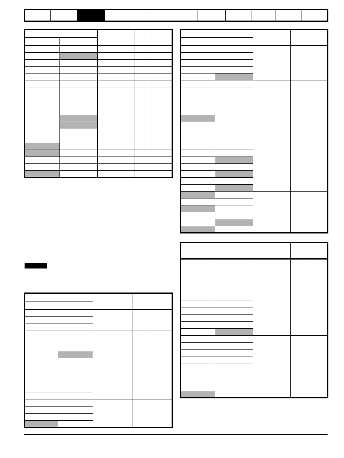
Table 3-17 400V (380V to 480V ± 10%) SFF Inductor
Drive
Heavy Duty Normal Duty
Part number mH Arms
SP1405 SP1405 4401-0162 3.16 9.5
SP1406
4401-0162 3.16 9.5
SP1406 4401-0163 2.50 12.0
SP2401 SP2401 4401-0164 1.875 16.0
SP2402 SP2402 4401-0165 1.20 25.0
SP2403
4401-0165 1.20 25.0
SP2404 SP2403 4401-0166 0.88 34.0
SP3401 SP2404 4401-0166 0.88 34.0
SP3402 SP3401 4401-0167 0.75 40.0
SP3403 SP3402 4401-0168 0.65 46.0
SP4401 SP3403 4401-0169 0.50 60.0
SP4401 4401-0170 0.39 70.0
SP4402 SP4402 4401-0171 0.315 96.0
SP4403
4401-0171 0.315 96.0
SP5401 SP4403 4401-0172 0.24 124.0
SP5402 SP5401 4401-0173 0.19 156.0
SP6401 SP5402 4401-0174 0.165 180.0
SP6402 SP6401 4401-0175 0.135 220.0
SP6402 4401-0176 0.10 300.0
SPMA1401
4401-0174 0.165 180.0
SPMA1402 SPMA1401 4401-0175 0.135 220.0
SPMA1402 4401-0176 0.10 300.0
SPMD1401
4401-0174 0.165 180.0
SPMD1402 SPMD1401 4401-0175 0.135 220.0
SPMD1403 SPMD1402 4401-0176 0.10 300.0
SPMD1404 SPMD1403 4401-0176 0.10 300.0
SPMD1404 4401-1205 0.08 350.0
Table 3-18 575V (500V to 575V ± 10%) SFF Inductor
Drive
Heavy Duty Normal Duty
Part number mH Arms
SP3505 SP3505 4401-1211 1.40 22.0
SP3506
4401-1211 1.40 22.0
SP3506 4401-1213 1.40 36.0
SP3507 SP3507 4401-1213 1.40 36.0
SP4601 SP4601 4401-1211 1.40 22.0
SP4602
4401-1211 1.40 22.0
SP4603 SP4602 4401-1213 1.40 36.0
SP4604 SP4603 4401-1214 1.20 43.0
SP4605 SP4604 4401-1215 1.00 52.0
SP4606 SP4605 4401-1216 0.80 63.0
SP5601 SP4606 4401-1217 0.60 85.0
SP5602 SP5601 4401-1218 0.50 100.0
SP6601 SP5602 4401-1219 0.40 125.0
SP6602 SP6601 4401-1220 0.35 144.0
SPMA1601
SPMD1601
4401-1219 0.40 125.0
4401-1219 0.40 125.0
SPMA1602 SPMA1601 4401-1220 0.35 144.0
SPMD1602 SPMD1601 4401-1220 0.35 144.0
SPMA1602 4401-1221 0.30 168.0
SPMD1602 4401-1221 0.30 168.0
SPMD1603 SP6602 4401-1221 0.30 168.0
SPMD1604 SPMD1603 4401-1222 0.26 192.0
SPMD1604 4401-1223 0.21 192.0
26 Unidrive SP Regen Installation Guide
www.controltechniques.com Issue Number: 2
Safety
Information
Introduction
Product
information
System
design
Mechanical
installation
Electrical
installation
Table 3-19 690V (690V ± 10%) SFF Inductor
Drive
Heavy Duty Normal Duty
Part number mH Arms
SP4601 SP4601 4401-1211 1.40 22.0
SP4602
4401-1211 1.40 22.0
SP4603 SP4602 4401-1213 1.40 36.0
SP4604 SP4603 4401-1213 1.40 36.0
SP4605 SP4604 4401-1214 1.20 43.0
SP4606 SP4605 4401-1215 1.00 52.0
SP5601 SP4606 4401-1216 0.80 63.0
SP5602 SP5601 4401-1217 0.60 85.0
SP6601 SP5602 4401-1218 0.50 100.0
SP6602 SP6601 4401-1219 0.40 125.0
SPMA1601
SPMD1601
4401-1218 0.50 100.0
4401-1218 0.50 100.0
SPMA1602 SPMA1601 4401-1219 0.40 125.0
SPMD1602 SPMD1601 4401-1219 0.40 125.0
SPMA1602 4401-1220 0.35 144.0
SPMD1602 4401-1220 0.35 144.0
SPMD1603 SP6602 4401-1220 0.35 144.0
SPMD1604 SPMD1603 4401-1221 0.30 168.0
SPMD1604 4401-1222 0.26 192.0
The inductors are standard three phase inductors (rated at Unidrive SP
Regen drive rated current). They carry only 50/60Hz current with a
negligible amount of high frequency current. The above switching
frequency filter inductors are calculated at 4% of the regen drives rating
using the following formula. A tolerance can be applied to the calculated
value in the range of, -10% to +30%.
L switching frequency filter mH = VLL / √3 x 1 / Irated x 0.04 x 1 / (2 x pi
x f).
Where:
VLL = Supply voltage line-to-line
f = Supply frequency
Irated = Drive rated current
NOTE
This calculation also gives the correct inductance value for a 480V, 60Hz
supply.
Table 3-20 200V (200V to 240V ± 10%) SFF Capacitors
Drive
Heavy Duty Normal Duty
Part number uF Arms
SP1203 SP1203
1664-1074 7 1.7SP1204 SP1204
SP2201 SP2201
SP2202 SP2202
SP2203 SP2203
SP3201 SP3201
1664-2174 16.6 4.3
SP3202
SP4201 SP3202
1665-8324 32 11SP4202 SP4201
SP4203 SP4202
SP5201 SP4203
1664-2644 64 17SP5202 SP5201
SPMD1201 SP5202
SPMD1202 SPMD1201
SPMD1203 SPMD1202
SPMD1204 SPMD1203
2 x 1664-2644 2 x 64 2 x 17
SPMD1204
Getting
started
Optimisation Parameters
Technical
data
Component
sizing
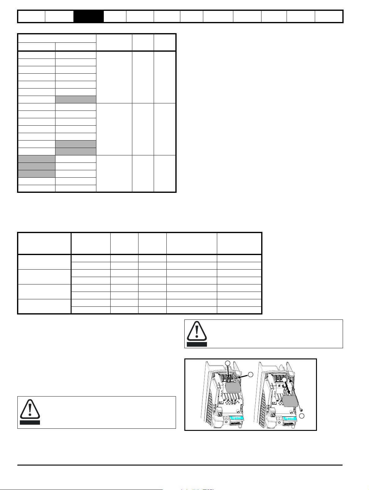
Table 3-21 400V (380V to 480V ± 10%) SFF Capacitors
Drive
Heavy Duty Normal Duty
Part number uF Arms
SP1405 SP1405
SP1406 SP1406
SP2401 SP2401
1610-7804 8 4.3
SP2402 SP2402
SP2403
SP2404 SP2403
SP3401 SP2404
SP3402 SP3401
SP3403 SP3402
1665-8324 32 11
SP4401 SP3403
SP4401
SP4402 SP4402
SP4403 SP4403
SP5401 SP5401
SP5402 SP5402
SP6401 SP6401
SP6402
1665-8484 48 17
SPMA1401 SPMA1401
SPMA1402
SPMD1401 SPMD1401
SPMD1402
SP6402
SPMA1402 SPMA1402
SPMD1402
1665-8774 77 26
SPMD1403 SPMD1403
SPMD1404
SPMD1404 2 x 1665-8394 2 x 39 2 x 13
Table 3-22 575V (500V to 575V ± 10%) SFF Capacitors
Drive
Heavy Duty Normal Duty
Part number uF Arms
SP3505 SP3505
SP3506 SP3506
SP3507 SP3507
SP4601 SP4601
SP4602 SP4602
SP4603 SP4603
1666-8113 11.2 5
SP4604 SP4604
SP4605 SP4605
SP4606 SP4606
SP5601 SP5601
SP5602
SP6601 SP5602
SP6602 SP6601
SPMA1601 SP6602
SPMA1602 SPMA1601
1666-8223 22.5 10
SPMD1601 SPMA1602
SPMD1602 SPMD1601
SPMD1603 SPMD1602
SPMD1604 SPMD1603
SPMD1604
2 x 1666-8233
2 x
22.5
Diagnostics
2 x 10
Unidr ive SP Re gen Inst allatio n Guide 27
Issue Number: 2 www.controltechniques.com
Safety
Information
Introduction
Product
information
System
design
Mechanical
installation
Electrical
installation
Getting
started
Optimisation Parameters
Technical
data
Component
sizing
Diagnostics
Table 3-23 690V (690V ± 10%) SFF Capacitors
Drive
Heavy Duty Normal Duty
Part number uF Arms
SP4601 SP4601
SP4602 SP4602
SP4603 SP4603
SP4604 SP4604
1668-7833 8.3 4.3
SP4605 SP4605
SP4606 SP4606
SP5601
SP5602 SP5601
SP6601 SP5602
SP6602 SP6601
SPMA1601 SPMA1601
1668-8163 16.6 8.6
SPMA1602 SPMD1601
SPMD1601
SPMD1602
SP6602
SPMA1602
SPMD1602
2 x 1668-8163 2 x 16.6 2 x 8.6
SPMD1603 SPMD1603
SPMD1604 SPMD1604
3.10.3 Varistors
AC line voltage transients can typically be caused by the switching of large items of plant or by lightning strikes on another part of the supply system.
If these transients are not suppressed they can cause damage to the insulation of the regen input inductors, or to the Regen drive electronics.
The following varistors should therefore be fitted as shown in section 4.2 Power connections .
Tab le 3-24 Va ris t or d a ta
Drive rating
200V
(200V to 240V±10%)
400V
(380V to 480V±10%)
575V
(500V to 575V±10%)
690V
(690V±10%)
Varisto r
voltage rating
V
RMS
Energy
rating
J
550 620 3 Line to line 2482-3291
680 760 3 Line to ground 2482-3211
550 620 3 Line to line 2482-3291
680 760 3 Line to ground 2482-3211
680 760 3 Line to line 2482-3211
1000 1200 3 Line to ground 2482-3218
385 550 6 2 in series line to line 2482-3262
1000 1200 3 Line to ground 2482-3218
Quantity
per
system
Configuration CT part number
3.10.4 EMC filters
In order to provide customers with a degree of flexibility, external EMC
filters have been sourced from two manufacturers, Schaffner and Epcos,
as detailed in both the Unidrive SP, and SPM User Guides.
For currents exceeding 300A up to 2500A, suitable filters are also
available from both Epcos and Schaffner as detailed.
• Epcos B84143-B250-5xx (range up to 2500A)
• Schaffner FN3359-300-99 (range up to 2400A)
These filters may not give strict conformity with EN6000-6-4 but in
conjunction with EMC installation guidelines they will reduce emissions
to sufficiently low levels to minimise the risk of disturbance.
When a EMC filter is used, the switching frequency filter
detailed must also be used. Failure to observe this may result
in the EMC filter becoming ineffective and being damaged.
CAUTION
Refer to section 6.4 EMC (Electromagnetic compatibility) on
page 77.
CAUTION
Figure 3-12 Removal of internal EMC filter (size 1 to 3)
Loosen / remove screws as shown (1) and (2).
Remove filter (3), and ensure the screws are replaced and re-tightened (4).
The internal EMC filter must be removed from the drive.
1
2
3
4
28 Unidrive SP Regen Installation Guide
www.controltechniques.com Issue Number: 2
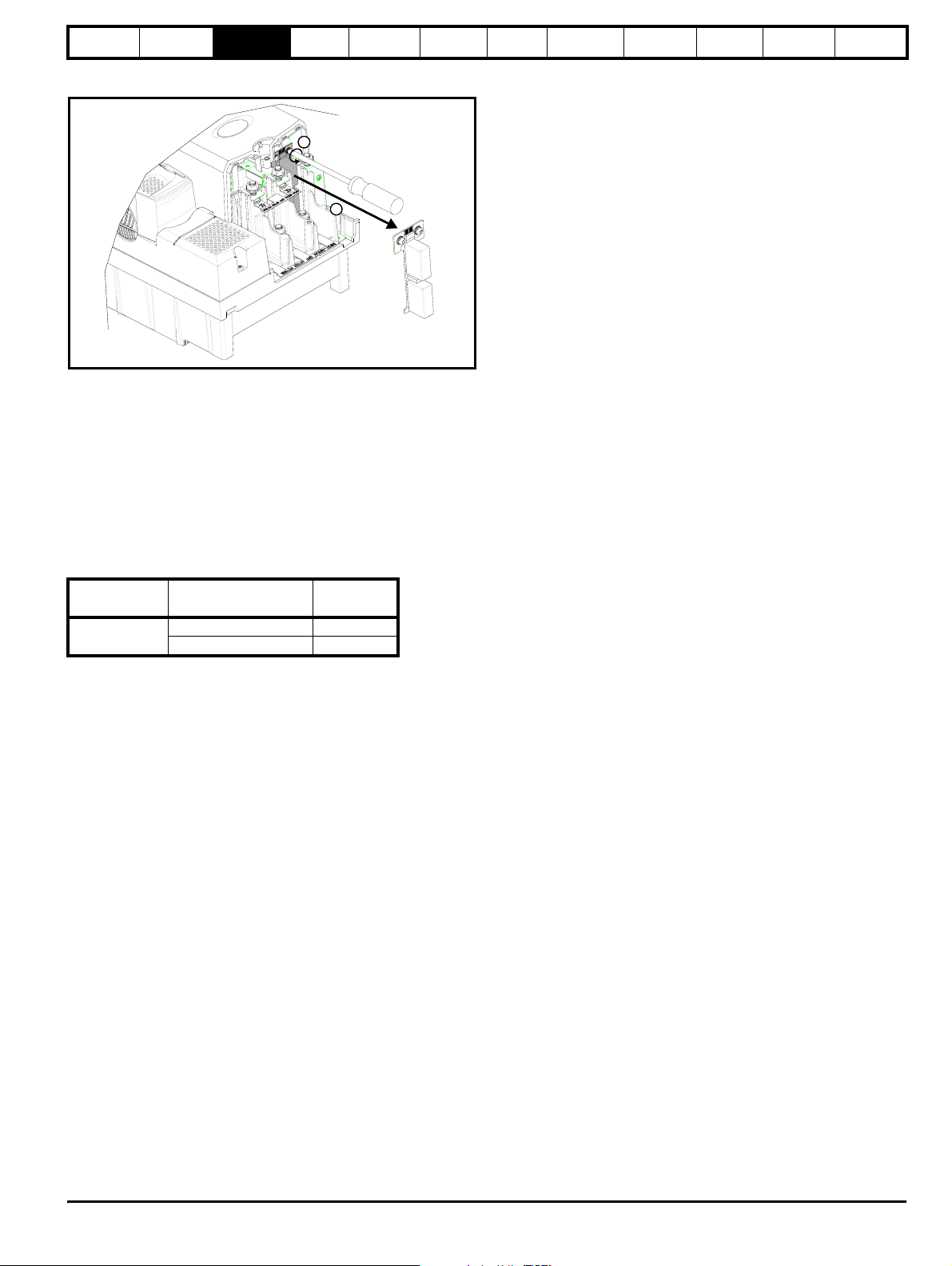
Safety
Information
Introduction
Product
information
System
design
Mechanical
installation
Electrical
installation
Figure 3-13 Removal of internal EMC filter (size 4 to 6 and the
SPMA/SPMD)
1
2
Loosen screws (1). Remove EMC filter in the direction shown (2).
3.10.5 External charging resistor
The following external charging resistors are available from Control
Techniques and can be used with a regen system consisting of multiple
regen, multiple motoring or single regen, multiple motoring drives. For
correct sizing of the charging resistor required, refer to section
11. 2 Resistor sizing for multiple drive systems on page 204. Also, see
section 10.4.2 Softstart resistor - type TG series on page 197 for further
technical data and thermal protection information on the following
resistors.
Table 3-25 External charging resistors
Drive
All sizes
External charging
resistor part no.
1270-3157 150
1270-2483 48
Ω
Getting
started
Optimisation Parameters
Technical
data
Component
sizing
Diagnostics
Unidr ive SP Re gen Inst allatio n Guide 29
Issue Number: 2 www.controltechniques.com

Safety
Information
Introduction
Product
information
System
design
Mechanical
installation
Electrical
installation
4 System design
4.1 Introduction
The sizing of a regen system must take into account the following
factors:
1. Line voltage variation
2. Motor rated current, rated voltage and power factor
3. Maximum required power and overload requirements
4. Heavy Duty / Normal Duty Regen drive ratings
In general, when designing a regen system, equal Regen and motoring
drive rated currents will work correctly. However, care must be taken to
ensure that under worst case supply conditions the Regen drive is able
to supply / absorb all the required power including total system losses.
If the Regen drive is unable to supply the full power required by the
motoring drive(s), the DC bus voltage will drop, and in severe cases may
lose synchronisation with the AC supply and trip. If the Regen drive is
unable to regenerate the full power from the motoring drive(s) into the
DC bus, then the Regen drive and motoring drive(s) will trip on overvoltage.
4.1.1 Single Regen, single motoring drive
The following calculations can be carried out for either a single Regen
drive, motoring drive system or single Regen drive, multiple motoring
drive system.
Example
In the case of a 23A (Normal Duty), SP2403 operating in regen mode
from a 400V supply, and a SP2403 driving a 400V rated, 0.85 pf motor:
The rated power of the Regen drive is:
3 Rated current× Supply voltage×
= 1.73 x 23 x 400
= 15.9kW
The motoring drive can supply power:
3 Rated current× Motor voltage Power factor××
= 1.73 x 23 x 400 x 0.85
= 13.5kW
Drive losses
2 x Unidrive SP 2403 = 626W
When the motoring drive is supplying rated current to the motor, the
Regen drive needs to provide 13.5kW, plus drive losses = 14.126kW.
The Regen drive can supply 15.9kW at rated current, which is ample, in
this case.
Conversely, in some cases, a Regen drive of the same rating as the
motoring drive, may not be able to supply enough power, as the
following example shows:
Example
In the case of a 96A (Heavy Duty), SP4403 operating in regen mode,
and a SP4403 driving a 75kW, 400V, 0.95pf motor:
If the motoring drive is supplying 175% maximum current, and the
Regen drive has its 380V supply at the lower limits of -10% (342Vac),
then, with a regen current limit of 150%:
Getting
started
Optimisation Parameters
Technical
data
Component
sizing
Diagnostics
requirement to 112.352kW. However, this Regen drive is only capable of
supplying approximately 85.1kW and therefore a drive of a larger rating
is required.
4.1.2 Multiple motoring drives
In multi-drive configurations, the Regen drive must be of a sufficient size
to supply the net peak power demanded by the combined load of all
motoring drives plus the combined losses, including its own losses.
Due to the effects of increased DC bus capacitance, there is a limit to the
number of motoring drives that can be supplied from a Regen drive. This
is true irrespective of the balance of power between the motoring drives
and the Regen drive.
The previous calculations can be used for the sizing of multiple motoring
drives also.
4.2 Power connections
The following section covers the power connections required for
Unidrive SP regen systems.
• For single Regen, single motoring systems, AC supply connections
are made to L1, L2 and L3 drive terminals and the drive’s internal
soft start circuit is used for power-up.
• The single Regen, multiple motoring and multiple regen, multiple
motoring systems require an external charging circuit due to the
extra capacitance from the additional drives. No AC connections are
made to the Regen drive’s L1, L2 and L3 terminals. The external
charging circuit can consist of either the SPMC solution or an
external charging resistor as shown in the following.
• For the regen brake resistor replacement system, the motoring
drive’s internal soft start is used for power-up with no AC
connections to L1, L2, L3 on the Regen drive.
For control circuit connections refer to section 6.6 Control
connections on page 83.
NOTE
If the regen system is not a standard configuration or changes are
required to the following systems and set ups, contact the supplier of the
drive.
The Regen drive maximum available power is:
3 150% Rated current×× Supply voltage×
= 1.73 x 1.5 x 96 x 342
= 85.1kW
The motoring drives maximum. power is:
3 175% Rated current× Motor voltage×× Power factor×
= 1.73 x 1.75 x 96 x 400 x 0.95
= 110.4kW
Drive losses
2 x Unidrive SP 4403 = 1.952kW
The Regen drive is also required to supply the Regen and motoring drive
losses in this example 1.952kW which brings the total power
30 Unidrive SP Regen Installation Guide
www.controltechniques.com Issue Number: 2
 Loading...