

Emerson SOUTHTOWNE CF4900BS00, SOUTHTOWNE CF4900ORB00, SOUTHTOWNE CF4900VS00 Owner's Manual
Part No. F40BP74850000 Form No. BP7485
Revision: 131201 U.L. Model No.: CF4900
READ AND SAVE THESE INSTRUCTIONS
SOUTHTOWNE
™
54” Ceiling Fan Owner's Manual
CF4900BS00
Brushed Steel
CF4900VS00
Vintage Steel
Model Numbers
CF4900ORB00
Oil Rubbed Bronze
Net Weight: ??.? Lbs.
Questions, problems, missing parts: Before returning to the store call
Emerson Electric Customer Service
8 a.m. - 6 p.m., Eastern, Monday-Friday
1-800-654-3545
www.emersonfans.com
BP7485 Southtowne CF4900 12/4/13 10:15 AM Page 1
2
Safety Instructions
TO REDUCE THE RISK OF FIRE, ELECTRICAL SHOCK,
OR INJURY TO PERSONS, OBSERVE THE
FOLLOWING:
a. Use this unit only in a manner intended by the
manufacturer. If you have questions, contact the
manufacturer.
b. Before servicing or cleaning unit, switch power off
at service panel and lock service panel
disconnecting means to prevent power from being
switched on accidentally. When the service
disconnecting means cannot be locked, securely
fasten a warning device, such as a tag, to the
service panel.
WARNING
!
Additional Safety Instructions for Installation
1. To avoid possible shock, be sure electricity is turned
off at the fuse box before wiring, and do not operate
fan without blades.
2. All wiring must be in accordance with the National
Electrical Code “ANSI/NFPA 70-2014” and Local
Electrical Codes. Use the National Electrical Code if
Local Codes do not exist. The ceiling fan must be
grounded as a precaution against possible electrical
shock. Electrical installation should be made or
approved by a licensed electrician.
3. The outlet box and joist must be securely mounted
and capable of reliably supporting at least 50 pounds.
Use only U.L. outlet boxes listed as “Acceptable for
Fan Support of 22.7 kg. (50 lbs.) or less”, and use the
mounting screws provided with the outlet box. Most
outlet boxes commonly used for support of light
fixtures are not acceptable for fan support and may
need to be replaced. Consult a qualified electrician if
in doubt.
4. The downrod furnished with the fan provides the
minimum recommended floor to fan blade clearance
for an 8 foot ceiling.
5. The fan must be mounted with the fan blades at least
7 feet from the floor to prevent accidental contact with
the fan blades.
6. Follow the recommended instructions for the proper
method of wiring your ceiling fan. If you do not know
enough about electrical wiring, have your fan installed
by a licensed electrician.
WARNING: To reduce the risk of electrical shock, this
fan must be installed with an isolating wall control/
switch.
NOTE: This fan is suitable for use with solid-state speed
controls.
WARNING: This product is designed to use only those
parts supplied with this product and/or any accessories
designated specifically for use this product by Emerson
Electric Co. Substitution of parts or accessories not
designated for use with this product by Emerson could
result in personal injury or property damage.
WARNING: To reduce the risk of personal injury, do not
bend the blade flange when installing the blade flanges,
balancing the blades or cleaning the fan. Do not insert
foreign objects in between rotating fan blades.
WARNING: To avoid fire, shock or injury, do not use an
Emerson or any other brand of control not specifically
approved for this fan.
NOTE: All setscrews must be checked and re-tightened
where necessary before installation.
NOTE: This fan is suitable for use in wet locations when
installed in a GFCI protected branch circuit.
1. Read your owner’s manual carefully and keep it for
future reference.
2. Be careful of the fan and blades when cleaning,
painting, or working near the fan. Always turn off the
power to the ceiling fan before servicing.
3. Do not put anything into the fan blades while they are
turning.
4. Do not operate reversing switch until fan blades have
come to a complete stop.
DATE CODE:
The date code of this fan may be found on the box, stamped in ink on a white label. You should record
this data above and keep it in a safe place for future use.
U.L. Model No.: CF4900
READ AND SAVE THESE INSTRUCTIONS
Table of Contents
Section Page
Safety Instructions . . . . . . . . . . . . . . . . . . . . . . . . . . . . . . . .2
1. Unpacking Instructions . . . . . . . . . . . . . . . . . . . . . . . . .3-4
2. Electrical Requirements . . . . . . . . . . . . . . . . . . . . . . . . . .4
3. Ceiling Fan Assembly . . . . . . . . . . . . . . . . . . . . . . . . . .5-7
4. How to Hang Your Ceiling Fan . . . . . . . . . . . . . . . . . . .8-9
5. How to Wire Your Ceiling Fan . . . . . . . . . . . . . . . . . .10-12
6. Light Kit Assembly . . . . . . . . . . . . . . . . . . . . . . . . . . .13-14
7. No Light Cover Assembly . . . . . . . . . . . . . . . . . . . . .15-16
Section Page
8. Wall Control Procedures . . . . . . . . . . . . . . . . . . . . . .16-22
9. Maintenance . . . . . . . . . . . . . . . . . . . . . . . . . . . . . . . . . .23
10. Accessories . . . . . . . . . . . . . . . . . . . . . . . . . . . . . . . . . .23
11. Repair Parts . . . . . . . . . . . . . . . . . . . . . . . . . . . . . . .24-25
12. Trouble Shooting . . . . . . . . . . . . . . . . . . . . . . . . . . . . . .26
13. Remote Control Trouble Shooting . . . . . . . . . . . . . . . .26
Ceiling Fan Limited Warranty . . . . . . . . . . . . . . . . . . . . . . .27
BP7485 Southtowne CF4900 12/4/13 10:15 AM Page 2
1. Unpacking Instructions
3
emersonfans.com
Please contact 1-800-654-3545 for further assistance
U.L. Model No.: CF4900
This product is designed to use only those parts
supplied with this product and/or any accessories
designated specifically for use with this product by
Emerson Electric Co. Substitution of parts or
accessories not designated for use with this product
by Emerson Electric Co. could result in personal injury
or property damage.
WARNING
!
Do not install or use fan if any part is damaged or
missing. Call Toll-Free:
1-800-654-3545
WARNING
!
1.1
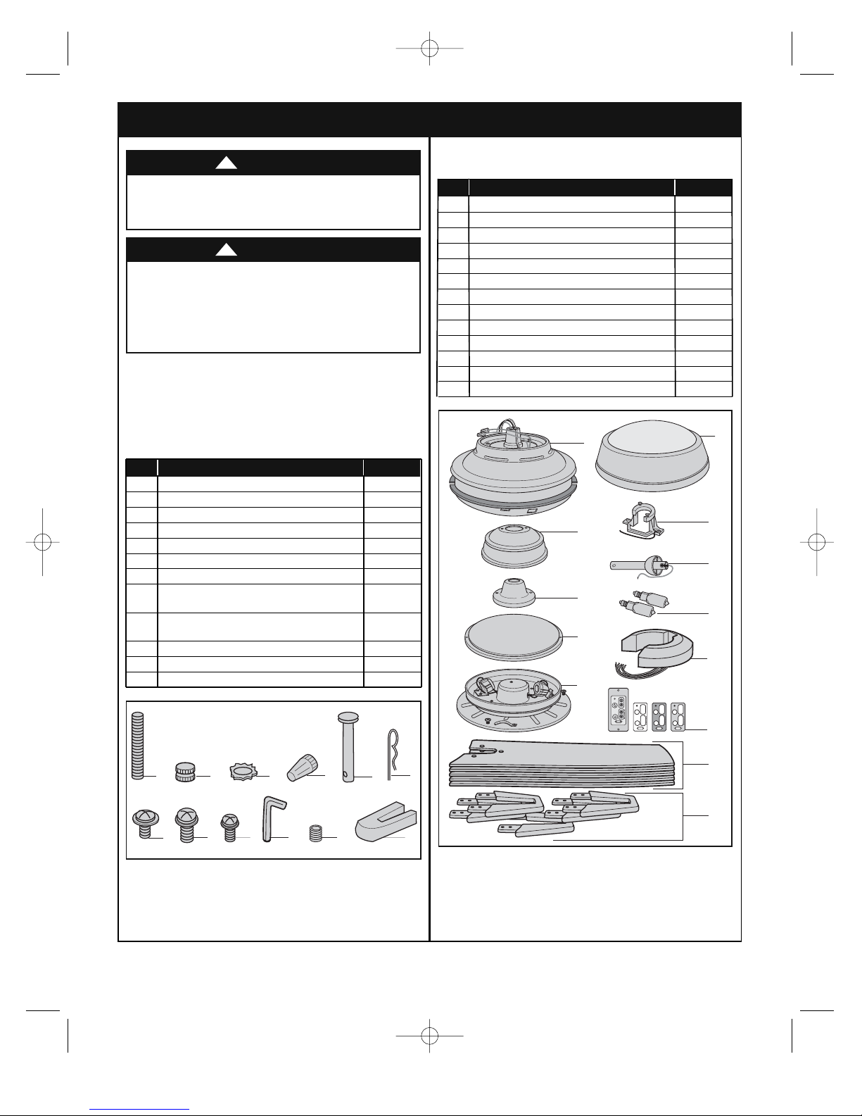
Check to see that you have received the following parts:
NOTE: If you are uncertain of part description, refer
to exploded view illustration.
1.2
Remove the fan motor assembly from the protective
plastic bag.
HARDWARE CONTENTS
PACKAGE CONTENTS
NOTE: Place the parts from the loose parts bags in
a small container to keep them from being lost.
If any parts are missing, contact your local
retailer or catalog outlet for replacement before
proceeding.
Part Description Quantity
1 Threaded Studs, #8-32 x 1-1/4” 4
2 Knurled Knobs, #8-32 4
3 Lockwashers, External Tooth #8 4
4 Wire Connectors, 12 ga. 5
5 Clevis Pin 1
6 Hairpin Clip 1
7 #10-32 x 1/4” Washer Head Blade Screws 15
8 1/4-20 x 3/8” Pan Head Screws
with Lockwashers 21
9 1/4-20 x 3/8” Oval Head Screw
with Lockwasher (spare) 1
10 Setscrew Wrench 1
11 Setscrew 1
12 Blade Balance Kit 1
Part Description Quantity
A Fan Motor Assembly 1
B Ceiling Cover 1
C Coupler Cover 1
D No Light Cover 1
E Light Kit Assembly 1
F Glass Assembly 1
G Fan Blades 5
H Fan Blades Flanges 5
I Hanger Bracket 1
J Hanger Ball/4.5” Downrod Assembly 1
K 50-Watt Halogen Bulbs 2
L RCK55 Receiver 1
M SW605 Wall Control, 6-Speed LED 1
BP7485 Southtowne CF4900 12/4/13 10:15 AM Page 3
1
2
3
4
6
5
A
B
C
D
E
OFF ON
F
I
J
K
L
M
G
9
7
8
10
11
12
H
Before assembling your ceiling fan, refer to section on
proper method of wiring your fan (page 10). If you feel
you do not have enough wiring knowledge or
experience, have your fan installed by a licensed
electrician.
WARNING
!
This Manual Is Designed to Make it as Easy as Possible for You to Assemble,
Install, Operate and Maintain Your Ceiling Fan
Tools Needed for Assembly
One Phillips head screwdriver One stepladder
One 1/4” blade screwdriver One wire stripper
Materials
Wiring outlet box and box connectors must be of type
required by the local code. The minimum wire would be
a 3-conductor (2-wire with ground) of following size:
Installed Wire Length
Wire Size A.W.G.
Up to 50 ft. 14
50-100 ft. 12
1.3
Remove and discard the cardboard shipping retainer
securing the motor hub in the motor housing assembly.
1.4
Place the fan assembly into the upper foam pad with the
bottom of the motor facing up.
The upper foam pad serves as a holder for the fan
during assembly.
4
U.L. Model No.: CF4900
2. Electrical Requirements
Your new ceiling fan will require a grounded electrical
supply line of 120 volts AC, 60 Hz, 15 amp circuit.
To reduce the risk of fire, electric shock, or personal
injury, mount fan to outlet box marked “Acceptable for
Fan Support of 22.7 kg. (50 lbs.) or less”, and use
screws supplied with outlet box. Most outlet boxes
commonly used for support of light fixtures are not
acceptable for fan support and may need to be
replaced. Consult a qualified electrician if in doubt.
WARNING
!
Turning off wall switch is not sufficient. To avoid
possible electrical shock, be sure electricity is turned
off at the main fuse box before wiring. All wiring must
be in accordance with National and Local codes and
the ceiling fan must be properly grounded as a
precaution against possible electrical shock.
WARNING
!
To avoid fire or shock, follow all wiring instructions
carefully.
Any electrical work not described in these
instructions should be done or approved by a licensed
electrician.
WARNING
!
The outlet box must be securely anchored and capable
of withstanding a load of at least 50 pounds.
If your fan is to replace an existing ceiling light fixture,
turn electricity off at the main fuse box at this time and
remove the existing light fixture.
1. Unpacking Instructions (continued)
BP7485 Southtowne CF4900 12/4/13 10:15 AM Page 4
FAN MOTOR
ASSEMBLY
CARDBOARD
SHIPPING
RETAINER (2)
3. Ceiling Fan Assembly
5
emersonfans.com
Please contact 1-800-654-3545 for further assistance
U.L. Model No.: CF4900
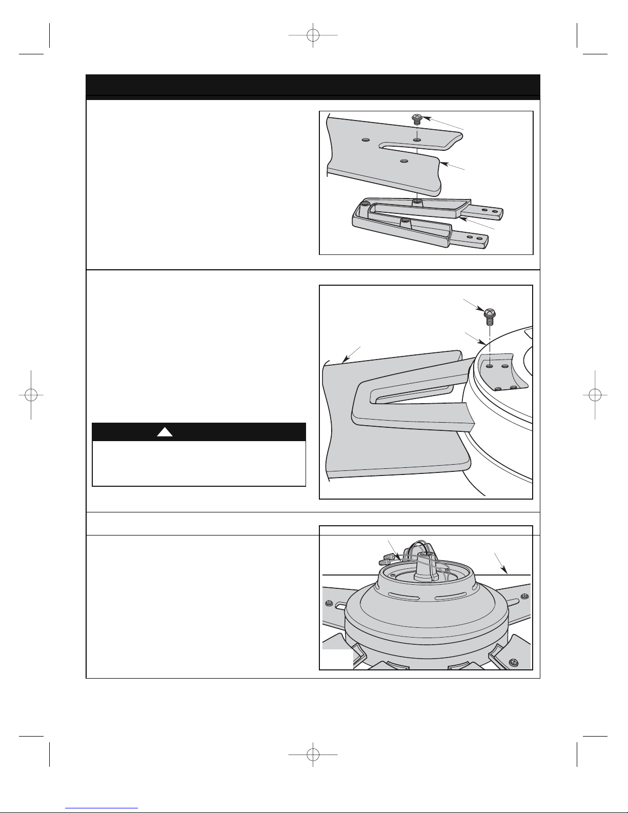
3.1
Position the fan blade on top of the blade flange by
aligning the three raised bosses into the blade mounting
holes.
Install the three #10-32 x 1/4” Washer Head Blade
Screws into the mounting holes of the fan blade
assembly and tighten securely (Figure 1). I
Complete the installation of the remaining four blades
per the above instructions.
Figure 1
3.2
Slide the fan blade assembly through the blade slot in
the fan motor housing assembly (Figure 2).
Mount the fan blade assembly to fan motor housing
assembly using four #10-32 x 5/8” oval head blade
screws (Figure 2).
NOTE: Take care not to scratch fan motor housing
assembly when installing blade assemblies.
Complete the installation of the remaining four blade
assemblies per the above instructions.
Figure 2
To reduce the risk of personal injury, do not bend the
blade flange when installing the blade flanges,
balancing the blades or cleaning the fan. Do not insert
foreign objects in between rotating fan blades.
WARNING
!
3.3
Turn the partially assembled ceiling fan right side up for
final installation. Place the fan carefully onto the top of
the styrofoam as not to bend the ceiling fan blades
(Figure 3).
Figure 3
BP7485 Southtowne CF4900 12/4/13 10:15 AM Page 5
#10-32 x 14" WASHER
HEAD BLADE SCREWS
(3 per blade assembly)
#10-32 x 5/8" OVAL HEAD BLADE SCREW (4)
MOTOR HOUSING ASSEMBLY
FAN BLADE ASSEMBLY
FAN BLADE (5)
FAN BLADE
FLANGE (5)
CEILING FAN
(partially assembled)
STYROFOAM
6
U.L. Model No.: CF4900
3. Ceiling Fan Assembly (continued)
Figure 4
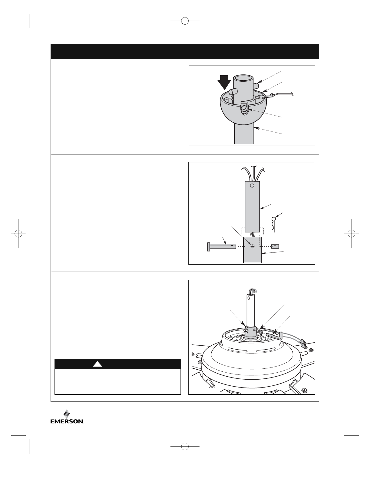
3.4
Remove the hanger ball by loosening the setscrew in
the hanger ball until the ball falls freely down the
downrod (Figure 4).
Remove the pin from the downrod, then remove the
hanger ball. Retain the pin and hanger ball for
reinstallation in Step 3.10.
Figure 5
It is critical that the clevis pin in the motor coupling is
properly installed and the setscrews securely
tightened. Failure to verify that the pin and setscrews
are properly installed could result in the fan falling.
WARNING
!
3.5
Separate, untwist and unkink the three 80” motor leads.
Route the motor lead wires through the downrod.
Align the clevis pin holes in the downrod with the holes
in the motor coupling. Install the clevis pin and secure
with the hairpin clip (Figure 5).
The clevis pin must go through the holes in the motor
coupling and the holes in the downrod. Be sure to push
the straight leg of the hairpin clip through the hole near
the end of the clevis pin until the curved portion of the
hairpin clip snaps around the clevis pin.
The hairpin clip must be properly installed to prevent the
clevis pin from working loose. Pull on the downrod to
make sure the clevis pin is properly installed.
Figure 6
3.6
Insert the setscrew (supplied in loose parts bag) into the
motor coupler hole until it rest against the downrod.
Securely tighten the setscrew using the 5/32" setscrew
wrench (provided).
Pull up on the downrod to make sure the setscrew is
firmly installed against the motor coupler (Figure 6).
NOTE: The setscrew must be properly installed as
described above, or fan wobble could result.
BP7485 Southtowne CF4900 12/4/13 10:15 AM Page 6
PIN
HANGER BALL
SETSCREW (2)
SETSCREW
CLEVIS PIN
CLEVIS PIN
MOTOR
COUPLING
SETSCREW
DOWNROD
DOWNROD
DOWNROD
HAIRPIN
CLIP
MOTOR
COUPLING
HAIRPIN
CLIP
MOTOR
COUPLING
SETSCREW (1)
5/32"
SETSCREW
WRENCH
7
emersonfans.com
Please contact 1-800-654-3545 for further assistance
U.L. Model No.: CF4900
3. Ceiling Fan Assembly (continued)
Figure 8
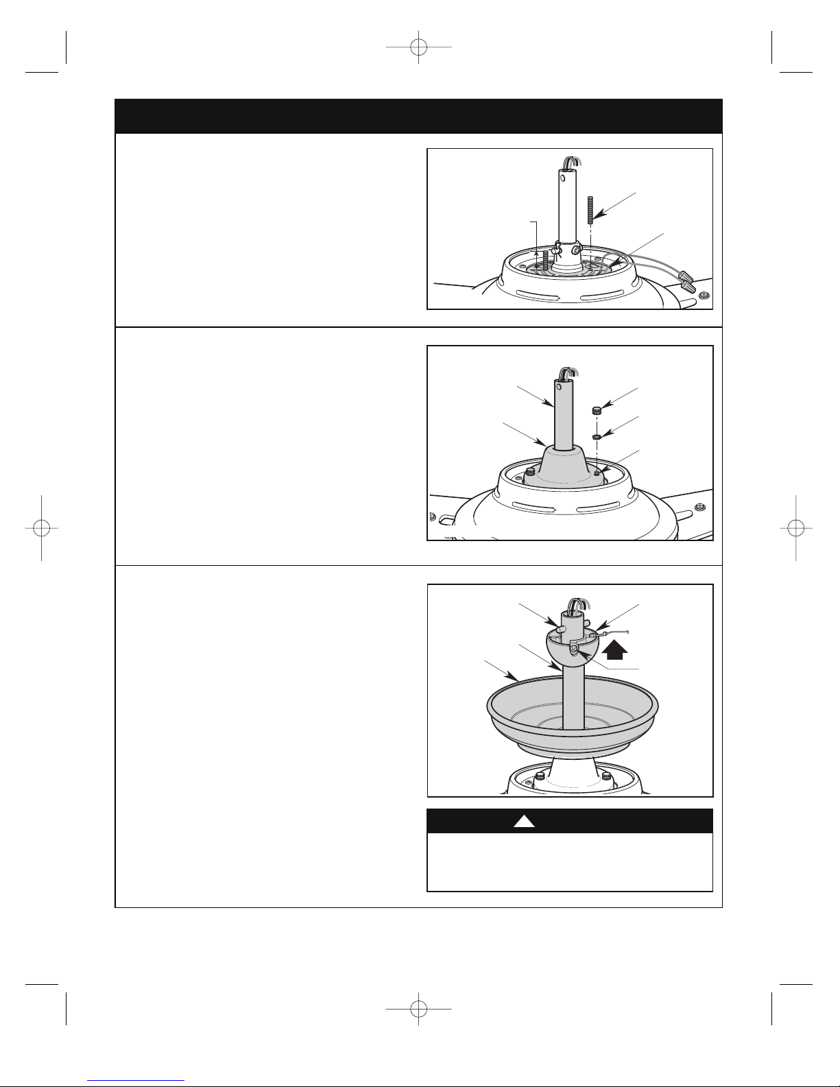
3.8
NOTE: Make sure the red and brown leads are
capped with wire connectors. During installation of
coupler cover, be sure the red, brown and yellow
wires and wire connectors are completely inside
motor coupler cover and not pinched between the
motor coupler cover and motor.
Slide the motor coupler cover over the downrod and
rotate the cover until the threaded studs protrude
(Figure 8).
Install the two #8 external tooth lockwashers and #8-32
knurled knobs (supplied) to secure the motor coupler
cover (Figure 8).
Figure 7
3.7
Screw two #8-32 x 1-1/4” threaded studs (provided) into
the motor (Figure 7).
Leave approximately 7/8” of the stud extending above
the motor.
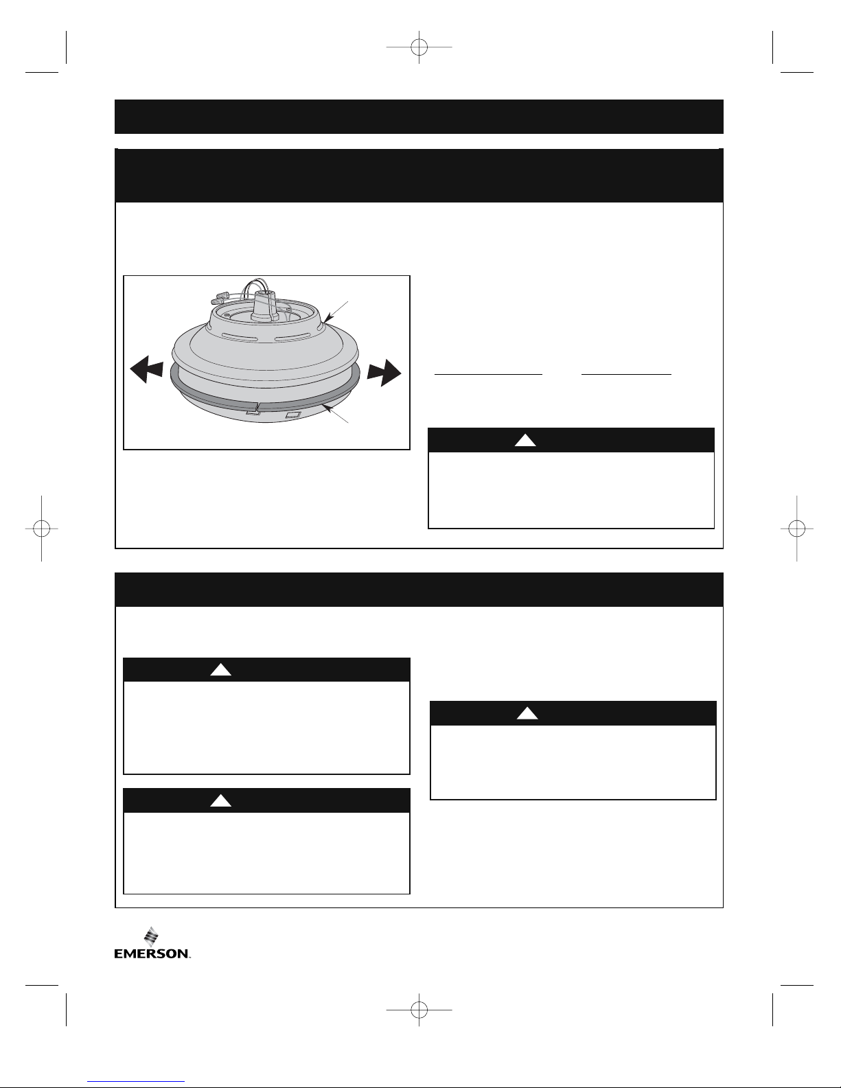
3.9
Pass the 80-inch long motor leads through the opening
in the ceiling cover. Be sure the cover is oriented
correctly (Figure 9).
3.10
Reinstall the hanger ball (Figure 9) on the downrod as
follows. Route the motor leads through the downrod.
Position the pin through the two holes in the downrod
and align the ball so the pin is captured in the groove in
the top of the hanger ball. Pull the hanger ball up tight
against the pin and securely tighten the setscrew in the
hanger ball. A loose setscrew could create fan wobble.
3.11
The fan comes with blue, black and white leads that are
80-inches long. Before installing the fan, measure up
approximately 6 to 9-inches above top of hanger
ball/downrod assembly. Cut off excess leads and strip
back insulation 1/2-inch from end of leads.
It is critical that the pin in the hanger ball is properly
installed and the setscrew securely tightened. Failure
to verify that the pin and setscrew are properly
installed could result in the fan falling.
WARNING
!
Figure 9
BP7485 Southtowne CF4900 12/4/13 10:15 AM Page 7
7/8"
#8-32 x 1-1/4"
THREADED
STUD (2)
MOTOR
DOWNROD
MOTOR
COUPLER
COVER
DOWNROD
CEILING
COVER
PIN
#8-32 KNURLED
KNOB (2)
#8 EXTERNAL
TOOTH
LOCKWASHER (2)
#8-32 x 1-1/4"
THREADED
STUD (2)
HANGER BALL
SETSCREW
8
U.L. Model No.: CF4900
The outlet box and joist must be securely mounted and
capable of supporting at least 50 lbs. Use only a U.L.
outlet box listed as “Acceptable for Fan Support of
22.7 kg. (50 lbs.) or less”.
WARNING
!
To reduce the risk of fire, electric shock, or personal
injury, mount fan to outlet box marked “Acceptable for
Fan Support of 22.7 kg. (50 lbs.) or less”, and use
screws supplied with outlet box. Most outlet boxes
commonly used for support of light fixtures are not
acceptable for fan support and may need to be
replaced. Consult a qualified electrician if in doubt.
WARNING
!
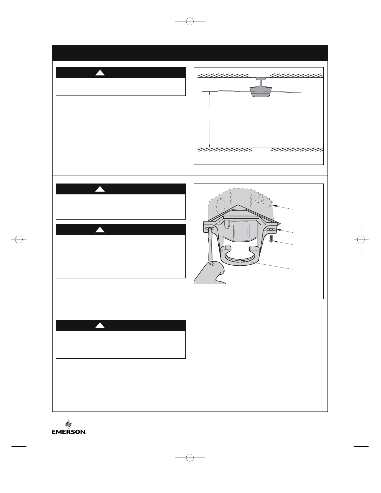
Figure 10
4. How to Hang Your Ceiling Fan
The fan must be hung with at least 7' of clearance from
floor to blades (Figure 10).
WARNING
!
4.1
Securely attach the hanger bracket to the outlet box
using the two screws supplied with the outlet box.
(Figure 11.)
Hanger bracket must seat firmly against outlet box. If
the outlet box is recessed, remove wall board until
bracket contacts box. If bracket and/or outlet box are
not securely attached, the fan could wobble or fall.
WARNING
!
Figure 11
BP7485 Southtowne CF4900 12/4/13 10:15 AM Page 8
AT LEAST
7'
CEILING
FLOOR
OUTLET
BOX
HANGER
BRACKET
TWO SCREWS
SUPPLIED WITH
OUTLET BOX
TAB
9
emersonfans.com
Please contact 1-800-654-3545 for further assistance
U.L. Model No.: CF4900
4. How to Hang Your Ceiling Fan (continued)
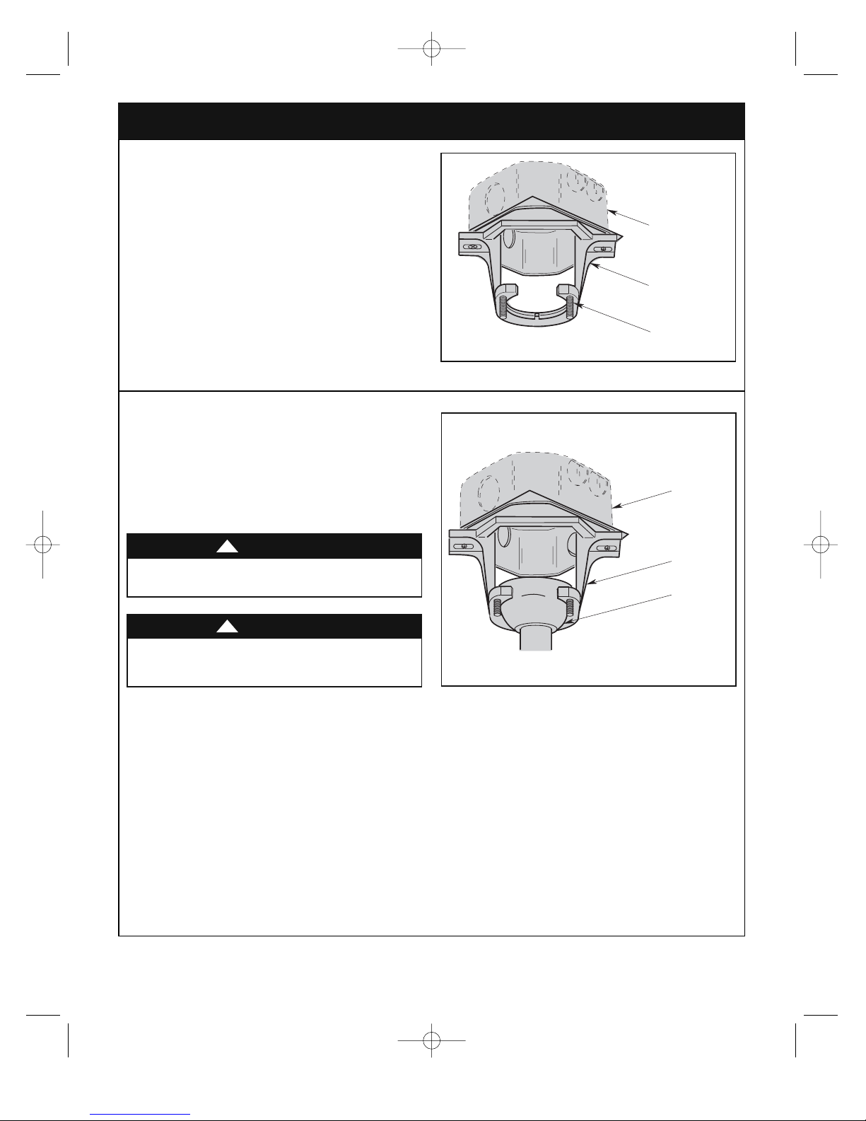
4.2
Screw the two 1-1/4” threaded studs (supplied) into the
tapped holes in the hanger bracket (Figure 12).
Figure 12
To avoid possible fire or shock, do not pinch wires
between the hanger ball/downrod assembly and
hanger bracket.
WARNING
!
Failure to seat tab in groove could cause damage to
electrical wires and possible shock or fire hazard.
WARNING
!
Figure 13
4.3
Carefully lift the fan and seat the hanger ball/
downrod assembly on the hanger bracket that was just
attached to the outlet box (Figure 13).
Be sure the groove in the ball is lined up with tab on the
hanger bracket (Figure 12).
BP7485 Southtowne CF4900 12/4/13 10:15 AM Page 9
OUTLET BOX
HANGER BRACKET
1-1/4" THREADED
STUDS (2)
NOTE: CEILING COVER, SUPPLY
WIRES AND FAN WIRES OMITTED
FOR CLARITY.
OUTLET
BOX
HANGER
BRACKET
HANGER BALL/
DOWNROD
ASSEMBLY
 Loading...