

Emerson SolaHD SDUMBUSCARD, SolaHD SDUPNETCARD, SolaHD SDUECATCARD Instruction Manual

Uninterruptible Power Systems
Instruction Manual
SDU AC - A SERIES COMM CARDS
Active Card
Passive Card

ii | Contents
CONTENTS
1.0 Introduction 1
1.1 Active Cards (Example: SDUENETIPCARD) . . . . . . . . . . . . . . . . . . . . . . . . . . . . . . . . . . . . 1
1.1.1 SDUENETIPCARD . . . . . . . . . . . . . . . . . . . . . . . . . . . . . . . . . . . . . . . . . . . . . . . . . 1
1.1.2 Other Industrial Protocols . . . . . . . . . . . . . . . . . . . . . . . . . . . . . . . . . . . . . . . . . . . . . 1
1.2 Passive Card (SDUCFRELAYCARD) . . . . . . . . . . . . . . . . . . . . . . . . . . . . . . . . . . . . . . . . 1
2.0 Installation 2
3.0 System Features and General Description 4
3.1 Identiction . . . . . . . . . . . . . . . . . . . . . . . . . . . . . . . . . . . . . . . . . . . . . . . . 9
4.0 Interface and Mechanical Description 12
4.1 SDU COMM CARD Interface To UPS . . . . . . . . . . . . . . . . . . . . . . . . . . . . . . . . . . . . . . . 12
4.2 SDU COMM CARD Interface To End-User Network . . . . . . . . . . . . . . . . . . . . . . . . . . . . . . . . 13
4.2.1 SDUENETIPCARD Connectors for Network Interface . . . . . . . . . . . . . . . . . . . . . . . . . . . . . . . . 13
4.2.2 SDUCFRELAYCARD Interface . . . . . . . . . . . . . . . . . . . . . . . . . . . . . . . . . . . . . . . . . . . 13
5.0 Specications 15
6.0 Data Exchange 16
6.1 Network Data Access . . . . . . . . . . . . . . . . . . . . . . . . . . . . . . . . . . . . . . . . . . . . . . 16
6.2 Process Data Exchange . . . . . . . . . . . . . . . . . . . . . . . . . . . . . . . . . . . . . . . . . . . . . 18
6.3 Web Server . . . . . . . . . . . . . . . . . . . . . . . . . . . . . . . . . . . . . . . . . . . . . . . . . . . 19
7.0 Operating and Storage Temperature 20
8.0 Warranty 20

SDU AC A SERIES COMM CARDS INSTRUCTION MANUAL | iii
FIGURES
Figure 1: Installing Communication Card to UPS . . . . . . . . . . . . . . . . . . . . . . . . . . . . . . . . . . . 2
Figure 2: Installing Communication Card to UPS; Special Instruction . . . . . . . . . . . . . . . . . . . . . . . . . 3
Figure 3: SDUENETIPCARD Construction . . . . . . . . . . . . . . . . . . . . . . . . . . . . . . . . . . . . . . 4
Figure 4 : Front View - SDUENETIPCARD Details . . . . . . . . . . . . . . . . . . . . . . . . . . . . . . . . . . . 5
Figure 5: Front View - SDUECATCARD Details . . . . . . . . . . . . . . . . . . . . . . . . . . . . . . . . . . . . 6
Figure 6: Front View - SDUMBUSCARD Details . . . . . . . . . . . . . . . . . . . . . . . . . . . . . . . . . . . . 7
Figure 7: Front View - SDUPNETCARD Details . . . . . . . . . . . . . . . . . . . . . . . . . . . . . . . . . . . . 8
Figure 8 : SDUCFRELAYCARD Front Face and Designations . . . . . . . . . . . . . . . . . . . . . . . . . . . . . . 10
Figure 9 : SDUCFRELAYCARD Application Block Diagram . . . . . . . . . . . . . . . . . . . . . . . . . . . . . . . 11
Figure 10 : SDU COMM CARD Interface to UPS. . . . . . . . . . . . . . . . . . . . . . . . . . . . . . . . . . . . 12
Figure 11 : RJ45 Connector For Ethernet Style Card . . . . . . . . . . . . . . . . . . . . . . . . . . . . . . . . . 13
Figure 12 : SDUCFRELAYCARD Front Face . . . . . . . . . . . . . . . . . . . . . . . . . . . . . . . . . . . . . . 13
Figure 13 : SDUCFRELAYCARD PIN Standby Circuit. . . . . . . . . . . . . . . . . . . . . . . . . . . . . . . . . . 14
Figure 14 : Web Server Window Example . . . . . . . . . . . . . . . . . . . . . . . . . . . . . . . . . . . . . . 19
TABLES
Table 1: LED Status for SDUENETIPCARD . . . . . . . . . . . . . . . . . . . . . . . . . . . . . . . . . . . . . . 5
Table 2: LED Status for SDUECATCARD . . . . . . . . . . . . . . . . . . . . . . . . . . . . . . . . . . . . . . . 6
Table 3: Ethernet Interface (RJ45 Connectors) for SDUECATCARD . . . . . . . . . . . . . . . . . . . . . . . . . . . 6
Table 4: LED Status for SDUMBUSCARD . . . . . . . . . . . . . . . . . . . . . . . . . . . . . . . . . . . . . . . 7
Table 5: LED Status for SDUPNETCARD . . . . . . . . . . . . . . . . . . . . . . . . . . . . . . . . . . . . . . . 8
Table 6: Ethernet Interface (RJ45 Connectors) for SDUPNETCARD . . . . . . . . . . . . . . . . . . . . . . . . . . 8
Table 7: Network Identications . . . . . . . . . . . . . . . . . . . . . . . . . . . . . . . . . . . . . . . . . . 9
Table 8 : SDUCFRELAYCARD Relay Logic and LED State. . . . . . . . . . . . . . . . . . . . . . . . . . . . . . . . 11
Table 9 : SDUCFRELAYCARD PIN Conguration . . . . . . . . . . . . . . . . . . . . . . . . . . . . . . . . . . . 14
Table 10 : Variables Exchange on the Network. . . . . . . . . . . . . . . . . . . . . . . . . . . . . . . . . . . . 16

While every precaution has been taken to ensure accuracy and completeness in this manual, Appleton Grp LLC d/b/a Appleton Group
assumes no responsibility, and disclaims all liability for damages resulting from use of this information or for any errors or omissions.
The SolaHD and Emerson logos are registered in the U.S. Patent and Trademark Oce. All other product or service names are the
property of their registered owners.
©2018 Appleton Grp LLC d/b/a Appleton Group. All rights reserved. Specications are subject to change without notice.
EtherNet/IP™ is a registered trademark of ODVA™ www.odva.org
Aunque se han tomado todas las precauciones para asegurar la exactitud y acuciosidad de este manual, SolaHD no asume
responsabilidad alguna, y rechaza toda responsabilidad por daños que pudieran resultar debido al uso de esta información o por
cualquier error u omisión.
©2018 SolaHD. Todos los derechos reservados en el mundo entero. Las especicaciones pueden cambiar sin previo aviso.
EtherNet/IP™ is a registered trademark of ODVA™ www.odva.org
El nombre y el logotipo de ®SolaHD son marcas registradas de Appleton Grp LLC d/b/a Appleton Group. Todos los nombre
mencionados son marcas comerciales o registradas de sus respectivos titulares.
Bien que toutes les précautions aient été prises an d’assurer que les renseignements du présent manuel sont complets et exacts, Sola/
Hevi-Duty n’assume aucune responsabilité, et décline toute responsabilité pour des dommages découlant de l’utilisation de cette
information ou de toute erreur ou omission.
©2018 SolaHD Tous droits réservés mondialement. Les caractéristiques techniques sont sujettes à modication sans préavis.
Le nom et le logo ®SolaHD sont des marques déposées de Appleton Grp LLC d/b/a Appleton Group. Tous les noms évoqués sont des
marques de commerce ou des marques déposées de leurs propriétaires respectifs.
EtherNet/IP™ is a registered trademark of ODVA™ www.odva.org

SDU AC A SERIES COMM CARDS INSTRUCTION MANUAL | 1
1.0 Introduction
The new SDU AC - A Series UPS has added capability to communicate to systems or networks through modular COMM CARDS.
1.1 Active Cards
Plug-in modules that provides the SDU AC - A Series UPS network exibility and a modular solution. It is especially suitable for both
general purpose and for high-end applications with large I/O data transfer, fast network cycles and synchronization demands. Utilizing
a common Ethernet module that allows your chosen Ethernet protocol in a specic communications module to be chosen for your
application.
1.1.1 SDUENETIPCARD
The COMM CARD for EtherNet/IP™ is a complete module which enables your products to communicate on an EtherNet/IP™
network. The module supports fast communication speeds, making it suitable also for high-end industrial devices. EtherNet/IP™
SDUENETIPCARD has been tested and approved for conformance by the ODVA. More information about EtherNet/IP™ and the ODVA
can be obtained from the following website: www.odva.org.
1.1.2 Other Industrial Protocols
Modules to supports fast Industrial Internet communication speeds with other networks are being developed.
Contact your SolaHD representative for availability.
SDUMBUSCARD - Modbus TCP 2-port, COMM CARD which enables your products to communicate on an Modbus TCP network.
SDUPNETCARD - Pronet IRT 2-port, COMM CARD which enables your products to communicate on an Pronet network
SDUECATCARD - EtherCAT 2-port, COMM CARD which enables your products to communicate on an EtherCAT network
1.2 Passive Card
The SDUCFRELAYCARD supports digital I/O processing applications and is equipped with LED diagnostics. The SDUCFRELAYCARD is a
communication module used to control two 1-form-c SPDT relays (N.O.). Each relay contact side, N.O., C and N.C., is connected to three
pins of a 8 pin push-in connector. An optional external momentary switch can be connected to the remaining two interface pins 7-8 for
remote standby mode operation.
The CF Relay Card is a SELV circuit acts as an interface between the UPS and the end user system.2.0 Installation

1
1
2
TORX 8
0.25Nm
1
2
3
2 | 2.0 Installation
2.0 Installation
Only qualied personnel should install or service the card. Electrical safety precautions must be followed when installing or servicing
the SDUCFRELAYCARD. To prevent risk of electric shock, turn OFF and lock out all power sources to the UPS before making electrical
connections.
Remove the SDUCOMMCVR (COMM PORT COVER) from the UPS then slide through the slot the SDUCFRELAY CARD
For proper COMM CARD installation instructions, please refer to the SolaHD YouTube video: https://youtu.be/1wYElxdjL50
SDU COMM CARD
1
Card hook
1) When securing the module into the SDU, ensure that the card module is properly aligned into the CompactFlash socket inside the UPS prior to applying any force.
The card hook should be aligned with the PCB.
2
2) Turn the screws in a clockwise direction until ush. DO NOT OVER TORQUE. Recommended screw tightening torque is 0.25 N.m (0.18 lbf.ft).
CompactFlash
3) As the screws tighten, a fastening mechanism will lock on the PCB.
Figure1: Installing Communication Card to UPS
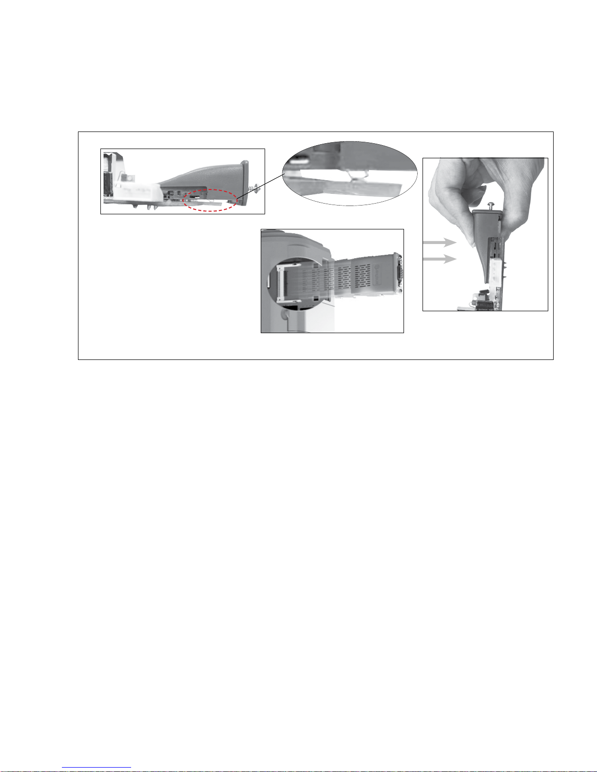
Note:
DO NOT force a COMM CARD into the COMM
PORT of your UPS. When inserting a COMM CARD,
remember to rst properly position and align
the card to the compact ash connector on the
PCB in the COMM PORT. Gradually insert while
compressing the ground spring pin on the bottom
of the card to the PCB in the port. Insert the COMM
CARD into the compact ash connector until it is
properly seated to the connector and PCB when
ush with the front surface of the UPS. After the
card is properly seated & positioned, tighten down
the card screws to properly secure the card.
SDU AC A SERIES COMM CARDS INSTRUCTION MANUAL | 3
Ground PIN
Figure 2: Installing Communication Card to UPS; Special Instruction

4 | 3.0 System Features and General Description
3.0 System Features and General Description
50-pin CompactFlash connector
Network Processor
Robust plastic housing
On-board DC/DC converter, opto
couplers and physical layer
Status LEDs x2
Tightening screws x2
Network specic connector
Integrated shield connections
(underside)
Figure 3: SDUENETIPCARD Construction
 Loading...