

Uninterruptible Power Systems
Instruction Manual
SDU AC - A SERIES COMM CARDS
Active Card
Passive Card

ii | Contents
CONTENTS
1.0 Introduction 1
1.1 Active Cards (Example: SDUENETIPCARD) . . . . . . . . . . . . . . . . . . . . . . . . . . . . . . . . . . . . 1
1.1.1 SDUENETIPCARD . . . . . . . . . . . . . . . . . . . . . . . . . . . . . . . . . . . . . . . . . . . . . . . . . 1
1.1.2 Other Industrial Protocols . . . . . . . . . . . . . . . . . . . . . . . . . . . . . . . . . . . . . . . . . . . . . 1
1.2 Passive Card (SDUCFRELAYCARD) . . . . . . . . . . . . . . . . . . . . . . . . . . . . . . . . . . . . . . . . 1
2.0 Installation 2
3.0 System Features and General Description 4
3.1 Identiction . . . . . . . . . . . . . . . . . . . . . . . . . . . . . . . . . . . . . . . . . . . . . . . . 9
4.0 Interface and Mechanical Description 12
4.1 SDU COMM CARD Interface To UPS . . . . . . . . . . . . . . . . . . . . . . . . . . . . . . . . . . . . . . . 12
4.2 SDU COMM CARD Interface To End-User Network . . . . . . . . . . . . . . . . . . . . . . . . . . . . . . . . 13
4.2.1 SDUENETIPCARD Connectors for Network Interface . . . . . . . . . . . . . . . . . . . . . . . . . . . . . . . . 13
4.2.2 SDUCFRELAYCARD Interface . . . . . . . . . . . . . . . . . . . . . . . . . . . . . . . . . . . . . . . . . . . 13
5.0 Specications 15
6.0 Data Exchange 16
6.1 Network Data Access . . . . . . . . . . . . . . . . . . . . . . . . . . . . . . . . . . . . . . . . . . . . . . 16
6.2 Process Data Exchange . . . . . . . . . . . . . . . . . . . . . . . . . . . . . . . . . . . . . . . . . . . . . 18
6.3 Web Server . . . . . . . . . . . . . . . . . . . . . . . . . . . . . . . . . . . . . . . . . . . . . . . . . . . 19
7.0 Operating and Storage Temperature 20
8.0 Warranty 20

SDU AC A SERIES COMM CARDS INSTRUCTION MANUAL | iii
FIGURES
Figure 1: Installing Communication Card to UPS . . . . . . . . . . . . . . . . . . . . . . . . . . . . . . . . . . . 2
Figure 2: Installing Communication Card to UPS; Special Instruction . . . . . . . . . . . . . . . . . . . . . . . . . 3
Figure 3: SDUENETIPCARD Construction . . . . . . . . . . . . . . . . . . . . . . . . . . . . . . . . . . . . . . 4
Figure 4 : Front View - SDUENETIPCARD Details . . . . . . . . . . . . . . . . . . . . . . . . . . . . . . . . . . . 5
Figure 5: Front View - SDUECATCARD Details . . . . . . . . . . . . . . . . . . . . . . . . . . . . . . . . . . . . 6
Figure 6: Front View - SDUMBUSCARD Details . . . . . . . . . . . . . . . . . . . . . . . . . . . . . . . . . . . . 7
Figure 7: Front View - SDUPNETCARD Details . . . . . . . . . . . . . . . . . . . . . . . . . . . . . . . . . . . . 8
Figure 8 : SDUCFRELAYCARD Front Face and Designations . . . . . . . . . . . . . . . . . . . . . . . . . . . . . . 10
Figure 9 : SDUCFRELAYCARD Application Block Diagram . . . . . . . . . . . . . . . . . . . . . . . . . . . . . . . 11
Figure 10 : SDU COMM CARD Interface to UPS. . . . . . . . . . . . . . . . . . . . . . . . . . . . . . . . . . . . 12
Figure 11 : RJ45 Connector For Ethernet Style Card . . . . . . . . . . . . . . . . . . . . . . . . . . . . . . . . . 13
Figure 12 : SDUCFRELAYCARD Front Face . . . . . . . . . . . . . . . . . . . . . . . . . . . . . . . . . . . . . . 13
Figure 13 : SDUCFRELAYCARD PIN Standby Circuit. . . . . . . . . . . . . . . . . . . . . . . . . . . . . . . . . . 14
Figure 14 : Web Server Window Example . . . . . . . . . . . . . . . . . . . . . . . . . . . . . . . . . . . . . . 19
TABLES
Table 1: LED Status for SDUENETIPCARD . . . . . . . . . . . . . . . . . . . . . . . . . . . . . . . . . . . . . . 5
Table 2: LED Status for SDUECATCARD . . . . . . . . . . . . . . . . . . . . . . . . . . . . . . . . . . . . . . . 6
Table 3: Ethernet Interface (RJ45 Connectors) for SDUECATCARD . . . . . . . . . . . . . . . . . . . . . . . . . . . 6
Table 4: LED Status for SDUMBUSCARD . . . . . . . . . . . . . . . . . . . . . . . . . . . . . . . . . . . . . . . 7
Table 5: LED Status for SDUPNETCARD . . . . . . . . . . . . . . . . . . . . . . . . . . . . . . . . . . . . . . . 8
Table 6: Ethernet Interface (RJ45 Connectors) for SDUPNETCARD . . . . . . . . . . . . . . . . . . . . . . . . . . 8
Table 7: Network Identications . . . . . . . . . . . . . . . . . . . . . . . . . . . . . . . . . . . . . . . . . . 9
Table 8 : SDUCFRELAYCARD Relay Logic and LED State. . . . . . . . . . . . . . . . . . . . . . . . . . . . . . . . 11
Table 9 : SDUCFRELAYCARD PIN Conguration . . . . . . . . . . . . . . . . . . . . . . . . . . . . . . . . . . . 14
Table 10 : Variables Exchange on the Network. . . . . . . . . . . . . . . . . . . . . . . . . . . . . . . . . . . . 16

While every precaution has been taken to ensure accuracy and completeness in this manual, Appleton Grp LLC d/b/a Appleton Group
assumes no responsibility, and disclaims all liability for damages resulting from use of this information or for any errors or omissions.
The SolaHD and Emerson logos are registered in the U.S. Patent and Trademark Oce. All other product or service names are the
property of their registered owners.
©2018 Appleton Grp LLC d/b/a Appleton Group. All rights reserved. Specications are subject to change without notice.
EtherNet/IP™ is a registered trademark of ODVA™ www.odva.org
Aunque se han tomado todas las precauciones para asegurar la exactitud y acuciosidad de este manual, SolaHD no asume
responsabilidad alguna, y rechaza toda responsabilidad por daños que pudieran resultar debido al uso de esta información o por
cualquier error u omisión.
©2018 SolaHD. Todos los derechos reservados en el mundo entero. Las especicaciones pueden cambiar sin previo aviso.
EtherNet/IP™ is a registered trademark of ODVA™ www.odva.org
El nombre y el logotipo de ®SolaHD son marcas registradas de Appleton Grp LLC d/b/a Appleton Group. Todos los nombre
mencionados son marcas comerciales o registradas de sus respectivos titulares.
Bien que toutes les précautions aient été prises an d’assurer que les renseignements du présent manuel sont complets et exacts, Sola/
Hevi-Duty n’assume aucune responsabilité, et décline toute responsabilité pour des dommages découlant de l’utilisation de cette
information ou de toute erreur ou omission.
©2018 SolaHD Tous droits réservés mondialement. Les caractéristiques techniques sont sujettes à modication sans préavis.
Le nom et le logo ®SolaHD sont des marques déposées de Appleton Grp LLC d/b/a Appleton Group. Tous les noms évoqués sont des
marques de commerce ou des marques déposées de leurs propriétaires respectifs.
EtherNet/IP™ is a registered trademark of ODVA™ www.odva.org

SDU AC A SERIES COMM CARDS INSTRUCTION MANUAL | 1
1.0 Introduction
The new SDU AC - A Series UPS has added capability to communicate to systems or networks through modular COMM CARDS.
1.1 Active Cards
Plug-in modules that provides the SDU AC - A Series UPS network exibility and a modular solution. It is especially suitable for both
general purpose and for high-end applications with large I/O data transfer, fast network cycles and synchronization demands. Utilizing
a common Ethernet module that allows your chosen Ethernet protocol in a specic communications module to be chosen for your
application.
1.1.1 SDUENETIPCARD
The COMM CARD for EtherNet/IP™ is a complete module which enables your products to communicate on an EtherNet/IP™
network. The module supports fast communication speeds, making it suitable also for high-end industrial devices. EtherNet/IP™
SDUENETIPCARD has been tested and approved for conformance by the ODVA. More information about EtherNet/IP™ and the ODVA
can be obtained from the following website: www.odva.org.
1.1.2 Other Industrial Protocols
Modules to supports fast Industrial Internet communication speeds with other networks are being developed.
Contact your SolaHD representative for availability.
SDUMBUSCARD - Modbus TCP 2-port, COMM CARD which enables your products to communicate on an Modbus TCP network.
SDUPNETCARD - Pronet IRT 2-port, COMM CARD which enables your products to communicate on an Pronet network
SDUECATCARD - EtherCAT 2-port, COMM CARD which enables your products to communicate on an EtherCAT network
1.2 Passive Card
The SDUCFRELAYCARD supports digital I/O processing applications and is equipped with LED diagnostics. The SDUCFRELAYCARD is a
communication module used to control two 1-form-c SPDT relays (N.O.). Each relay contact side, N.O., C and N.C., is connected to three
pins of a 8 pin push-in connector. An optional external momentary switch can be connected to the remaining two interface pins 7-8 for
remote standby mode operation.
The CF Relay Card is a SELV circuit acts as an interface between the UPS and the end user system.2.0 Installation

1
1
2
TORX 8
0.25Nm
1
2
3
2 | 2.0 Installation
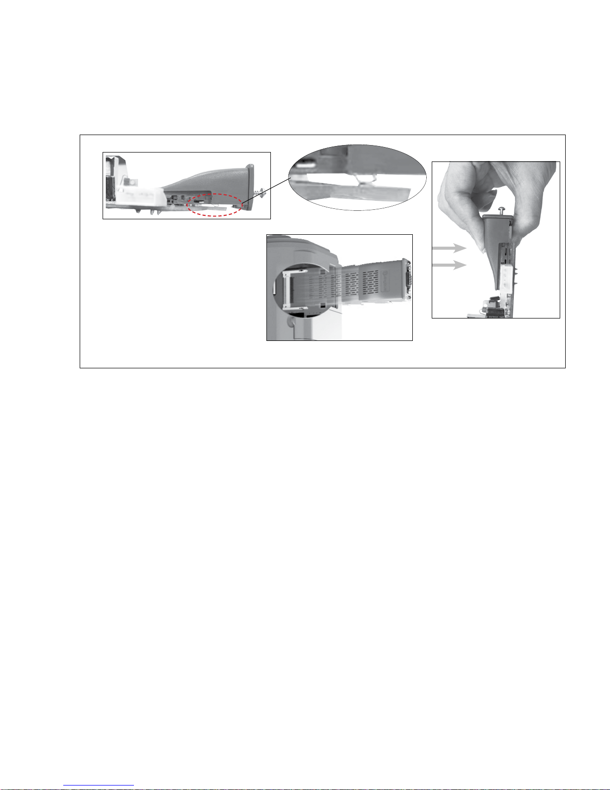
2.0 Installation
Only qualied personnel should install or service the card. Electrical safety precautions must be followed when installing or servicing
the SDUCFRELAYCARD. To prevent risk of electric shock, turn OFF and lock out all power sources to the UPS before making electrical
connections.
Remove the SDUCOMMCVR (COMM PORT COVER) from the UPS then slide through the slot the SDUCFRELAY CARD
For proper COMM CARD installation instructions, please refer to the SolaHD YouTube video: https://youtu.be/1wYElxdjL50
SDU COMM CARD
1
Card hook
1) When securing the module into the SDU, ensure that the card module is properly aligned into the CompactFlash socket inside the UPS prior to applying any force.
The card hook should be aligned with the PCB.
2
2) Turn the screws in a clockwise direction until ush. DO NOT OVER TORQUE. Recommended screw tightening torque is 0.25 N.m (0.18 lbf.ft).
CompactFlash
3) As the screws tighten, a fastening mechanism will lock on the PCB.
Figure1: Installing Communication Card to UPS
Note:
DO NOT force a COMM CARD into the COMM
PORT of your UPS. When inserting a COMM CARD,
remember to rst properly position and align
the card to the compact ash connector on the
PCB in the COMM PORT. Gradually insert while
compressing the ground spring pin on the bottom
of the card to the PCB in the port. Insert the COMM
CARD into the compact ash connector until it is
properly seated to the connector and PCB when
ush with the front surface of the UPS. After the
card is properly seated & positioned, tighten down
the card screws to properly secure the card.
SDU AC A SERIES COMM CARDS INSTRUCTION MANUAL | 3
Ground PIN
Figure 2: Installing Communication Card to UPS; Special Instruction

4 | 3.0 System Features and General Description
3.0 System Features and General Description
50-pin CompactFlash connector
Network Processor
Robust plastic housing
On-board DC/DC converter, opto
couplers and physical layer
Status LEDs x2
Tightening screws x2
Network specic connector
Integrated shield connections
(underside)
Figure 3: SDUENETIPCARD Construction

# Item Connector
SDU AC A SERIES COMM CARDS INSTRUCTION MANUAL | 5
1 Network Status LED
2 Model Status LED
3 Link/Activity LED (port 1)
4 Link/Activity LED (port 2)
Test sequences are performed on the Network and Module Status LEDs during startup.
Ethernet,
RJ45
1 2
NS MS
Figure 4 : Front View - SDUENETIPCARD Details
3
4
LED State Description
Network Status LED
O No power or no IP address
Green Online, one or more connections established (CIP Class 1 or 3)
Green, ashing Online, no connections established
Red Duplicate IP address, FATAL error
Red, ashing One or more connections timed out (CIP Class 1 or 3)
Module Status LED
O No power
Green Controlled by a Scanner in Run state
Green, ashing Not congured, or Scanner in Idle state
Red Major fault (EXCEPTION-state, FATAL error etc.)
Red, ashing Recoverable fault(s). Module is congured, but stored parameters dier from currently used parameters.
LINK/Activity LED 3/4
O No link, no activity
Green Link (100 Mbit/s) established
Green, ickering Activity (100 Mbit/s)
Yellow Link (10 Mbit/s) established
Yellow, ickering Activity (10 Mbit/s)
Table 1. LED Status for SDUENETIPCARD

6 | 3.0 System Features and General Description
# Item
1 RUN LED
2 ERROR LED
3 EtherCAT (IN port)
4 EtherCAT (OUT port)
5 Link/Activity (IN port)
6 Link/Activity (OUT port)
Figure 5 : Front View - SDUECATCARD Details
LED State Indication Description
RUN LED
O INIT EtherCAT device in ‘INIT’-state (or no power)
Green OPERATIONAL EtherCAT device in ‘OPERATIONAL’-state
Green, blinking PRE-OPERATIONAL EtherCAT device in ‘PRE-OPERATIONAL’-state
Green, single ash SAFE-OPERATIONAL EtherCAT device in ‘SAFE-OPERATIONAL’-state
Flickering BOOT The EtherCAT device is in ‘BOOT’ state
Red (Fatal Event)
ERR LED
O No error No error (or no power)
Red, blinking Invalid conguration
Red, single ash Unsolicited state change Slave device application has changed the EtherCAT state autonomously.
Red, double ash Sync Manager watchdog timeout Watchdog Functionality.
If RUN and ERR turn red, this indicates a fatal event, forcing the bus interface
to a physically passive state. Contact HMS technical support
State change received from master is not possible due to invalid register or
object settings.
Red Application controller failure
If RUN and ERR turn red, this indicates a fatal event, forcing the bus interface
to a physically passive state.
Flickering Booting error detected E.g. due to rmware download failure.
LINK/Activity LED
O No link Link not sensed (or no power)
Green Link sensed, no activity Link sensed, no trac detected
Green, ickering Link sensed, activity Link sensed, trac detected
Table 2. LED Status for SDUECATCARD
Pin # Signal Notes
1 Tx+ -
2 Tx- -
3 Rx+ -
4 -
Normally left unused; to ensure signal integrity, these pins
are tied together and terminated to PE via a lter circuit in
5 -
the module.
6 Rx- -
7 -
Normally left unused; to ensure signal integrity, these pins
are tied together and terminated to PE via a lter circuit in
8 -
Table 3. Ethernet Interface (RJ45 Connectors) for SDUECATCARD
the module.

SDU AC A SERIES COMM CARDS INSTRUCTION MANUAL | 7
# Item Connector
1 Network Status LED
2 Module Status LED
3 Link/Activity LED (port 1)
4 Link/Activity LED (port 2)
Test sequences are performed on the Network and Module Status LEDs during startup.
LED State Description
Network Status LED
O No IP address or in state EXCEPTION
Green At least one Modbus message received
Green, ashing Waiting for rst Modbus message
Red IP address conict detected, FATAL ERROR
Red, ashing
Module Status LED
O No power
Green Normal operation
Red Major fault, FATAL
Red, ashing Minor fault
Alternating red/green Firmware update from le system in progress
LINK/Activity LED 3/4
O No link, no activity
Green Link (100 Mbit/s) established
Green, ickering Activity (100 Mbit/s)
Yellow Link (10 Mbit/s) established
Yellow, ickering Activity (10 Mbit/s)
Ethernet, 45
Figure 6: Front View - SDUMBUSCARD Details
Connection timeout. No Modbus message has been received within the congured “process active
timeout” time
Table 4. LED Status for SDUMBUSCARD

8 | 3.0 System Features and General Description
# Item
1 Network Status LED
2 Module Status LED
3 Link/Activity LED (port 1)
4 Link/Activity LED (port 2)
Test sequences are performed on the Network and Module Status LEDs during startup.
Figure 7: Front View - SDUPNETCARD Details
LED State Description Comments
Network Status LED
O Oine
Green Online (RUN)
Green, 1 ash Online (STOP)
Green, blinking Blink Used by engineering tools to identify the node on the network
Red Fatal event
Red, 1 ash Station Name error Station Name not set
Red, 2 ashes IP address error IP address not set
Red, 3 ashes Conguration error Expected Identication diers from Real Identication
Module Status LED
O Not Initialized No power OR Module in SETUP or NW_INIT state.
Green Normal Operation Module has shifted from the NW_INIT state.
Green, 1 ash Diagnostic Event(s) Diagnostic event(s) present
Red
Alternating Red/Green Firmware update
LINK/Activity LED
O No Link No link, no communication present
Green Link Ethernet link established, no communication present
Green, ickering Activity Ethernet link established, communication present
Exception error Device in state EXCEPTION.
Fatal event
No power
No connection with IO Controller
Connection with IO Controller established
IO Controller in RUN state
Connection with IO Controller established
IO Controller in STOP state or IO data bad
IRT synchronization not nished
Major internal error (this indication is combined with a red module
status LED)
Major internal error (this indication is combined with a red net- work
status LED)
Do NOT power o the module. Turning the module o during this phase
could cause permanent damage.
Pin # Signal
1, 2, 4, 5
3 RD6 RD+
7 TD8 TD+
Housing Cable Shield
The Ethernet interface operates at 100 Mbit, full duplex, as required by PROFINET
Connected to chassis ground
over serial RC circuit
Table 6. Ethernet Interface (RJ45 Connectors) for SDUPNETCARD
Table 5. LED Status for SDUPNETCARD

SDU AC A SERIES COMM CARDS INSTRUCTION MANUAL | 9
3.1 Identication
Each Protocol has dierent parameters for identifying the SDU on the network. The following section will specify how the SDU will be
identied on each network. It is organized by the instance attribute number of the corresponding Host object. The SDU must respond
to requests with highlighted values. For default value it will suce for response with error response- indicated by Respond with Error.
For Respond with Error, it is not required to specify type.
Attr # Name Datatype Response Response Value
EtherNet/IP - SDUENETIPCARD (object 0xF8)
1 Vendor ID (from ODVA ) UINT16 1181
2 Device Type UINT16 Respond with Error
3 Product Code UINT16 2
4 Software Revision Struct of {UIN8 , UINT8} 1.03
5 Serial Number UINT32 Respond with Error
6 Product Name Array of CHAR SDU Industrial UPS
EtherCAT - SDUECATCARD (object 0xF5)
1 Vendor ID (from ETG* ) UINT32 0x00000906
2 Product Code UINT32 1F4
3 Major Rev UINT16 1
4 Minor Rev UINT16 03
5 Serial Number UINT32 Respond with Error
6 MFG Device Name Array of CHAR (max 64 ) SDU Industrial UPS
PROFINET - SDUPNETCARD (object 0xF6)
1 Device ID** UINT16 1F4
2 Vendor ID (from PNO*)** UINT16 Respond with Error
3 Station Type** Array of CHAR SDU Industrial UPS
8 I&M Order** Array of CHAR SDU Industrial UPS
9 I&M Serial Number Array of CHAR Respond with Error
19 System Description Array of CHAR SDU Industrial UPS
Modbus Host (object 0xFA)
1 Vendor Name Array of CHAR SOLA HD
2 Product Code*** Array of CHAR SDU Industrial UPS
3 Major Minor Rev*** Array of CHAR 1.03
4 Vendor URL Array of CHAR www.solaHD.com
5 Product Name Array of CHAR SDU Industrial UPS
6 Model Name Array of CHAR SDU Industrial UPS
7 User Application Name Array of CHAR Respond with Error
* PNO = PROFINET User Organization
** Entries must match the information located in the GSDML device File
*** Used IPCONFIG tool.
Table 7. Network Identications

10 | 3.0 System Features and General Description
(8Pin) PUSH-IN Type
Figure 8: SDUCFRELAYCARD Front Face and Designations
The SDUCFRELAYCARD contains the following:
1. Switching logic thrugh PINS 1-6, as a signal for the UPS condition relays.
2. Non-polarized ports, PINS 7-8 enable remote signaling and allow the UPS to go on STANDBY mode during BACK-UP MODE only.
When in STANDBY MODE, the UPS begins a 3 minute counter (maximum or set by user in UPSMON) that starts once STANDBY
MODE is activated by a momentary normally open switch or signal (minimum 1 second) before UPS will enter STANDBY mode.
3. A Bi-Color LED to represent UPS condition.

SDU AC A SERIES COMM CARDS INSTRUCTION MANUAL | 11
Condition
AC Failure BAT Low STANDBY Pin 1-2 Pin 2-3 Pin 4-5 Pin 5-6
No Fault GREEN GREEN x x
AC Fault UPS is on Back-Up Mode T RED GREEN x x
on Back-Up Mode - Battery is Low T T RED RED x x
Standby/Inverter is OFF T OFF OFF x x
Signal State (T-True)
LED Status Relay Logic
AC OK
Battery
Status
Connector Relay Pins (x-closed)
Table 8. SDUCFRELAYCARD Relay Logic and LED State
Figure 9: SDUCFRELAYCARD Application Block Diagram

12 | 4.0 Interface and Mechanical Description
4.0 Interface and Mechanical Description
4.1 SDU COMM CARD Interface TO UPS
The UPS COMM PORT is designed with a 50-pin compact ash connector as application connector. The UPS oers a host connector,
that is designed to simplify the mounting and to meet the demands for a secure and stable connection of the communication
modules.
NOTICE:
UPS should be turned OFF (powered down) when COMM CARD modules are installed or removed. Failure to observe this
practice may cause damage to the UPS or to the COMM CARD.
Figure 10: SDU COMM CARD Interface to UPS

SDU AC A SERIES COMM CARDS INSTRUCTION MANUAL | 13
4.2 SDU COMM CARD Interface to UPSk
4.2.1 The SDUENETIPCARD uses 2-port high speed RJ45 connectors for network interface.
Figure 11: RJ45 Connector For Ethernet Style Card
4.2.2 SDUCFRELAYCARD Interface
The SDUCFRELAYCARD has a 1x8 Push-In style connector. Push the plastic pin and insert the wire into the hole then release to lock it in
place. Each terminal position can accommodate 0.2 – 1.5 mm2 (AWG 24 – AWG 16) wire. The maximum force that should be applied on
the connector mechanism is 40 N (9lbs.).
The CF-RELAY-CARD is design for Safety Extra Low Voltage (SELV) circuit applications only.
Figure 12: SDUCFRELAYCARD Front Face
Pin 1 (BLUE)

14 | 4.0 Interface and Mechanical Description
PIN CONFIGURATION
Pin # Designation Description Comment
1 (BLUE) N.O. Normally Open
3 N.C. Normally Closed
4 N.O. Normally Open
6 N.C. Normally Closed
AC Failure2 C COM
Battery Low5 C COM
7 BLANK Input
(triggered by external N.O.
8 BLANK Output
Standby
momentary switch)
Table 9. SDUCFRELAYCARD PIN Conguration
PINS 1-6: Relays Switch
An SPDT relay is used as switching relay on the Relay Interface. This should be able to break 30VRMS, 42.4VPEAK or 60VDC @ 1A. The
maximum current on the relay contact side is 1A limited by the allowable trace width.
The STANDBY input is shown by the schematic. The TX signal going to UPS is normally HIGH unless UPS goes to BACK-UP Mode and the
STANDBY switch is pressed (minimum of 2 seconds). It requires a momentary, N.O. type switch to be connected on PINS 7 and 8. Upon
pressing the external switch (or simulating closure of pins 7 and 8 for a minimum of 2 seconds, the UPS will go into in STANDBY MODE
in approximately 3 minutes. ONLY in STANDBY MODE will the UPS auto recover once AC is restored.
Figure 13: SDUCFRELAYCARD PIN Standby Circuit

SDU AC A SERIES COMM CARDS INSTRUCTION MANUAL | 15
5.0 Specications
Catalog Number
Description
Nominal Voltage +3.3 V ±5 %
Standby signal Active low via normally open momentary switch
Frequency 50/60 Hz
LED Diagnostics Refer to diagram
Relay Logic Signals Refer to diagram —
Relay Contact Ratings 60V peak, 1A —
Passive Card (SDUCFRELAYCARD)
(SDUENETIPCARD, SDUMBUSCARD,
SDUPNETCARD, SDUECATCARD)
Input
Output
NS = Network Status, MS=Module Status
Active Cards
Refer to diagram
Case/Enclosure Material
H x W x D, in. (mm) 0.91 x 2.0 x 2.2 (23 x 50 x 55) approximate
Net Weight, oz. (g) 1.0 (28.4) approximate
Immunity/Emissions
Approvals
Temperature °F (°C)
Vibration
Shock
Humidity 1% to 90% RH, noncondensing; IEC 68-2-2, 68-2-3
Warranty 2 Years
MTBF (bellcore) 1,968,800 Hours
Emission EN 61000-6-4 EN55016-2-3 Radiated emission EN55022 Conducted emission
Immunity EN 61000-6-2 EN61000-4-2 Electrostatic discharge, EN61000-4-3 Radiated immunity.
EN61000-4-4 Fast transients/burst, EN61000-4-6 Conducted immunity
EN/IEC 60950-1 ; UL/CSA 60950-1 Pollution Degree 3 ; UL 508 Pollution Degree 3 CSA 107.1;
Operating: -40 to +158 (-40 to +70) Convection cooling; no forced air required.
Operating: IEC60068-2-6, Sine Wave: 10Hz to 500Hz @19.6m/S², displacement of 0.35mm,
Non-Operating: IEC60068-2-6, Random : 5hz to 500Hz (2.09Grms); 20 min per axis for all X,Y,Z direction.
Operating: IEC60068-2-27, Half Sine Wave: 10G for a duration of 11ms, shock for 1 direction (X axis).
Non-Operating: IEC60068-2-27, Half Sine Wave : 50G for duration of 11ms, 3 shocks for each 3 directions.
Housing: LCP(Liquid Crystal Polymer)
Color: Natural, Thermoplastic,UL 94 V-0
Weight & Dimensions
EMC
EU ROHS2,China ROHS2
Storage: -40 to +185 (-40 to +85)
60 min per axis for all X, Y, Z direction.
General Protection/
Safety
Approvals apply for ActiveCards. Contact Technical support for Passive Cards.
Protected against Continuous short -circuit, Continuous overload, Continuous open circuit. Galvanic Isolation:
Protection class 1 (IEC536), degree of protection IP20 (IEC 529) Safe low voltage: SELV (acc. EN60950); ROHS
I/P to O/P: 3KVac, I/P to GND: 1.5KVac, O/P to GND: 0.5KVac

16 | 6.0 Data Exchange
6.0 Data Exchange
6.1 Network Data Access
Access to SDU variables is provided by six monitoring instances, and one instance for control.
Table10 lists instance name, data type, and access rights. The instance numbers and access means are unique to each network type
ADI Inst # DataType Name Get/Set Process Data Exchange
101 CHAR Company 01(Get access)
102 CHAR UPS Model 01(Get access)
103 CHAR FW Ver. 01(Get access)
104 CHAR Rating 01(Get access)
105 UINT 8 Load Level(%)
106 UINT 8 Batt. Level(%)
107 UINT 16 Input Vol.(V )
108 UINT 16 Output Vol.(V )
109 UINT 8 Input Freq(Hz)
110 UINT 8 Output Freq(Hz)
111 UINT 8 UPS Status-1
112 UINT 8 UPS Status-2
113 UINT 8 Model Num.
114 UINT 8 PRE-SD min Time
115 UINT 8 PRE-SD sec Time
116 UINT 16 PRE-On min Time
117 UINT 8 UPS FW Ver.
118 UINT 8 Command
(UINT: Unassigned INTeger)
Table 10. Variables Exchange On The Network
09(Get access)
(Write Process Data)
09(Get access)
(Write Process Data)
09(Get access)
(Write Process Data)
09(Get access)
(Write Process Data)
09(Get access)
(Write Process Data)
09(Get access)
(Write Process Data)
09(Get access)
(Write Process Data)
09(Get access)
(Write Process Data)
09(Get access)
(Write Process Data)
09(Get access)
(Write Process Data)
09(Get access)
(Write Process Data)
09(Get access)
(Write Process Data)
09(Get access)
(Write Process Data)
11H(Get access)
(Read Process Data)
BYTE0
BYTE1
BYTE2,3
BYTE4,5
BYTE6
BYTE7
BYTE8
BYTE9
BYTE10
BYTE11
BYTE12
BYTE13,14
BYTE15

SDU AC A SERIES COMM CARDS INSTRUCTION MANUAL | 17
ADI Inst:102 UPS Model:
SDU850A
SDU850A-5
SDU500A
SDU500A-5
ADI Inst:104 Rating:
SDU850A: “120Vac 60Hz 7.1A”
SDU850A-5: “230Vac 50Hz 3.7A”
SDU500A: “120Vac 60Hz 4.2A”
SDU500A-5: “230Vac 50Hz 2.2A”
ADI Inst:105 Load level
Example: Byte=60 the load level is 60%
ADI Inst:106 Battery level
Example: Byte=60 the battery level is 60%
ADI Inst:107 Input voltage
Example: Byte=120 the input voltage is =120V
ADI Inst:108 Output voltage
Example: Byte=120 the output voltage is =120V
ADI Inst:109 Input frequency
Example: Byte=60 the input frequency is 60Hz
ADI Inst:110 Output frequency
Example: Byte=60 the output frequency is 60Hz
ADI Inst:111 UPS Status-1:
bit 0 is line fail (1 = INV, 0 = LINE)
bit 1 is low battery (1 = BAT LOW, 0 = NORMAL)
bit 2 reserved
bit 3 reserved
bit 4 reserved
bit 5 LOAD STATUS(1 = OVER LOAD, 0 = NORMAL)
bit 6 reserved
bit 7 SD MODE DISPLAY
ADI Inst :112 UPS Status-2:
bit 0 reserved
bit 1 BAT STATUS(1 = BAD, 0 = NORAML)
bit 2 TEST MODE (1 = TEST, 0, NORMAL)
bit 3 Buzzer Silence on/o (1= Silence)
Buzzer silence o = Alarm Enabled
Buzzer silence on = Alarm Disabled
bit 4 PRE-SD COUNT MODE (1 = ACTIVE)
bit 5 SCHEDULE COUNT MODE (1 = ACTIVE)
bit 6 DISBLE NO LOAD SHUTDOWN (1 = ACTIVE)
bit 7 reserved
ADI Inst: 113 UPS model number
32H =500VA 120V
39H =500VA 230V
52H =850VA 120V
59H =850VA 230V
ADI Inst: 114 PRE-SD min Time
UPS echo PRE-SD count down time----min
ADI Inst: 115 PRE-SD sec Time
UPS echo PRE-SD count down time----sec

18 | 6.0 Data Exchange
ADI Inst :116 PRE-On min Time
UPS echo schedule count time
ADI Inst :117 UPS FW Ver.
ADI Inst :108 Command (8Byte)(only read):
Receive data 3 : UPS self test
Receive data 4 N M 186 188 A B : SETUP Schedule ON/OFF Time(7byte)
N IS Schedule On Time HIGH BYTE MIN (0-255)
M IS Schedule On Time LOW BYTE MIN (0-255)
A IS Schedule O Time MIN (0-60)
B IS Schedule O Time SEC (0-59)
EX: Schedule On 1Day Schedule O 5min
4 5 160 186 188 5 0
UPS get command 5min UPS Shutdown 1440min UPS Restart
Receive data 5(Only for USB) : Buzzer silence on/o
Receive data “B”(Only for M40) : Buzzer silence o
Receive data “b”(Only for M40) : Buzzer silence on
Buzzer silence o = Alarm Enabled
Buzzer silence on = Alarm Disabled
Receive data “G” : ENABLE NO LOAD SHUT DOWN FUNCTION
Receive data “g” : DISABLE NO LOAD SHUT DOWN FUNCTION
Receive data 185 188 A B : UPS at Battery Mode PRE-SD COUNT
A IS Schedule O Time MIN (0-60)
B IS Schedule O Time SEC (0-59)
ADI Inst # = Instance number of the Host Application Data Object
DataType = Data type ( e.g. UINT8)
Name = Variable Name, available on some networks
Get/SET = is the value GET-able from the network
Process Data Exchange = variable able to be mapped to process data exchange
Range Min = minimum value for SET access. For range checking of inputs
Range Max = maximum value for SET access. For range checking of inputs
Update Rate = Approximate period of application update, for this value (may be asynchronous)
6.2 Process Data Exchange
The following lists the instances that are to mapped to process data exchange.
Input (16 Bytes):
BYTE0 Load Level(%)
Example: Byte0=60 the load level is 60%
BYTE1 Battery Level(%)
Example: Byte1=60 the battery level is 60%
BYTE2,3 Input voltage
Example: Byte2,3 =120 the input voltage is 120V
BYTE4,5 Output voltage
Example: Byte4,5=120 the output voltage is 120V
BYTE6 Input frequency
Example: Byte6=60 the input frequency is 60Hz
BYTE7 Output frequency
Example: Byte7=60 the output frequency is 60Hz

SDU AC A SERIES COMM CARDS INSTRUCTION MANUAL | 19
BYTE8 bit 0 is line fail (1 = INV, 0 = LINE)
bit 1 is low battery (1 = BAT LOW, 0 = NORMAL)
bit 2 reserved
bit 3 AVR (1 = AVR, 0 = NO AVR)
bit 4 AVR MODE (1 = BOOST, 0 = BUCK)
bit 5 LOAD STATUS(1 = OVER LOAD, 0 = NORMAL)
bit 6 reserved
bit 7 SD MODE DISPLAY
BYTE9 bit 0 reserved
bit 1 BAT STATUS(1 = BAD, 0 = NORAML)
bit 2 TEST MODE (1 = TEST, 0, NORMAL)
bit 3 Buzzer silence on/o (1=SILENCE)
Buzzer silence o = Alarm Enabled
Buzzer silence on = Alarm Disabled
bit 4 PRE-SD COUNT MODE (1 = ACTIVE)
bit 5 SCHEDULE COUNT MODE (1 = ACTIVE)
bit 6 DISBLE NO LOAD SHUTDOWN (1 = ACTIVE)
bit 7 reserved
BYTE10 UPS model number
32H =500VA 120V
39H =500VA 230V
52H =850VA 120V
59H =850VA 230V
BYTE11 UPS PRE-SD COUNT TIME MIN
BYTE12 UPS PRE-SD COUNT TIME SEC
BYTE13,14 UPS PRE-ON COUNT TIME
BYTE15 UPS FIRMWARE Ver
Output (8 Bytes):
The command Instance is mapped to output message structure is the same as outlined in the command instance chapter.
6.3 Web Server
SDU device has a web server that can be accessed via most browsers that can be used to both monitor and congure the UPS.
Instructions:
To use the web server, enter the IP address in your URL bar.
Figure 14. Web Server Window Example

20 | 7.0 Operating and Storage Temperature
7.0 Operating and Storage Temperature
Storage Conditions
Store the COMM CARD covered and upright in a cool, dry location.
The COMM CARDs can be operated and stored at -40 to +70 °C ( -40 to +158 °F).
Humidity is 5-95 % non-condensing
8.0 Warranty
Warranty Information
Please see “Terms and Conditions of Sale”.
Visit the Technical Support section of our Web site at: www.solahd.com
While every precaution has been taken to ensure accuracy and completeness in this manual, Appleton Grp LLC d/b/a Appleton Group
assumes no responsibility, and disclaims all liability for damages resulting from use of this information or for any errors or omissions.
The SolaHD and Emerson logos are registered in the U.S. Patent and Trademark Oce. All other product or service names are the
property of their registered owners.
©2018 Appleton Grp LLC d/b/a Appleton Group. All rights reserved. Specications are subject to change without notice.
EtherNet/IP™ is a registered trademark of ODVA™ www.odva.org
Aunque se han tomado todas las precauciones para asegurar la exactitud y acuciosidad de este manual, SolaHD no asume
responsabilidad alguna, y rechaza toda responsabilidad por daños que pudieran resultar debido al uso de esta información o por
cualquier error u omisión.
©2018 SolaHD. Todos los derechos reservados en el mundo entero. Las especicaciones pueden cambiar sin previo aviso.
EtherNet/IP™ is a registered trademark of ODVA™ www.odva.org
El nombre y el logotipo de ®SolaHD son marcas registradas de Appleton Grp LLC d/b/a Appleton Group. Todos los nombre
mencionados son marcas comerciales o registradas de sus respectivos titulares.
Bien que toutes les précautions aient été prises an d’assurer que les renseignements du présent manuel sont complets et exacts, Sola/
Hevi-Duty n’assume aucune responsabilité, et décline toute responsabilité pour des dommages découlant de l’utilisation de cette
information ou de toute erreur ou omission.
©2018 SolaHD Tous droits réservés mondialement. Les caractéristiques techniques sont sujettes à modication sans préavis.
Le nom et le logo ®SolaHD sont des marques déposées de Appleton Grp LLC d/b/a Appleton Group. Tous les noms évoqués sont des
marques de commerce ou des marques déposées de leurs propriétaires respectifs.
EtherNet/IP™ is a registered trademark of ODVA™ www.odva.org

SolaHD is our premium line of power
conversion and power quality solutions
products under Appleton Group, a business
unit of Emerson.
Emerson brings integrated manufacturing
solutions to diverse industries worldwide.
Our comprehensive product line, extensive
experience, world-class engineering and
global presence enable us to implement
solutions that give our customers the
competitive edge.
For over 150 years, our electrical product
brands have been providing a rich tradition
of long-term, practical, high quality
solutions with applications ranging from
the construction and safe operation of
petrochemical and process plants to
providing quality power that precisely
controls automotive robotic production.
Engineers, distributors, contractors,
electricians and site maintenance
professionals around the world trust
Emerson brands to make electrical
installations safer, more productive and more
reliable.
Appleton Group is organized into three
focused businesses that provide distributors
and end-users expert knowledge and
excellent service.
Electrical Construction Materials
This group is made up of the Appleton and
O-Z/Gedney brands. They manufacture
a broad range of electrical products
including conduit and cable ttings, plugs
and receptacles, enclosures and controls,
conduit bodies and industrial and hazardous
lighting. Whether the application is hazardous
location, industrial or commercial, the
electrical construction materials group has
the products to meet your needs.
Power Quality Solutions
The SolaHD brand oers the broadest
power quality line, including uninterruptible
power supplies, power conditioners, voltage
regulators, shielded transformers, surge
protection devices and power supplies.
Heating Cable Systems
This group is made up of the EasyHeat
and Nelson brands. They oer a broad
range of electrical heating cable products
for residential, commercial and industrial
applications.
Asia/Pacic
+ 65.6556.1100
Australia
+ 61.3.9721.0348
Canada
+ 1.888.765.2226
China
+ 86.21.3338.7000
Europe
+ 33.3.22.54.13.90
Mexico/Latin America
+ 52.55.5809.5049
Middle East/Africa/India
+ 971.4.811.8100
United States
+ 1.800.621.1506
Appleton Grp LLC
9377 W. Higgins Road
Rosemont, IL 60018
1.800.377.4384
solahd.com
While every precaution has been taken to ensure the accuracy and completeness of this literature, SolaHD Corporation assumes no responsibility and disclaims
all liability for damages resulting from use of this information or for any errors or omissions.
© 2018 SolaHD Corporation. All rights reserved throughout the world. Specications subject to change without notice.
® SolaHD is a registered trademark of SolaHD Corporation. All names referred to are trademarks or registered trademarks of their respective owners.
Appleton Grp LLC d/b/a Appleton Group. e Appleton, O-Z/Gedney, SolaHD, EasyHeat, Nelson and Emerson logos are registered in the U.S. Patent and Trademark Oce.
EasyHeat, Inc. is a wholly owned subsidiary of Appleton Grp LLC. All other product or service names are the property of their registered owners. © 2018, Appleton Grp LLC. All rights reserved.
P/N: A272-291 Rev. 2 02/2018
 Loading...