

Page 1
S M M C - 3 M A N U A L
Page 2

TABLE OF CONTENTS
GENERAL INFORMATION...........................................................................................................3
Pre-Programmed Configuration ............................................................................................................................ 3
WARNINGS....................................................................................................................................4
INSTALLATION..............................................................................................................................4
Pre-Programmed Connections.............................................................................................................................. 5
SYSTEM CHECK...........................................................................................................................6
OPERATION...................................................................................................................................7
Mode 1 – Independent ........................................................................................................................................... 7
Mode 2 – Priority .................................................................................................................................................... 7
Zone Assignment ................................................................................................................................................... 8
Manual Operation................................................................................................................................................... 8
Programming Instructions...................................................................................................................................... 9
TROUBLESHOOTING GUIDE ...................................................................................................12
SMMC-3 Control panel (access cover removed) ............................................................................................... 13
SPECIFICATIONS .......................................................................................................................14
Sensor Extension Wire Specifications ................................................................................................................ 14
LIMITED WARRANTY AND LIABILITY.....................................................................................15
Page 3
GE NER AL INFOR M ATION
Manual Override
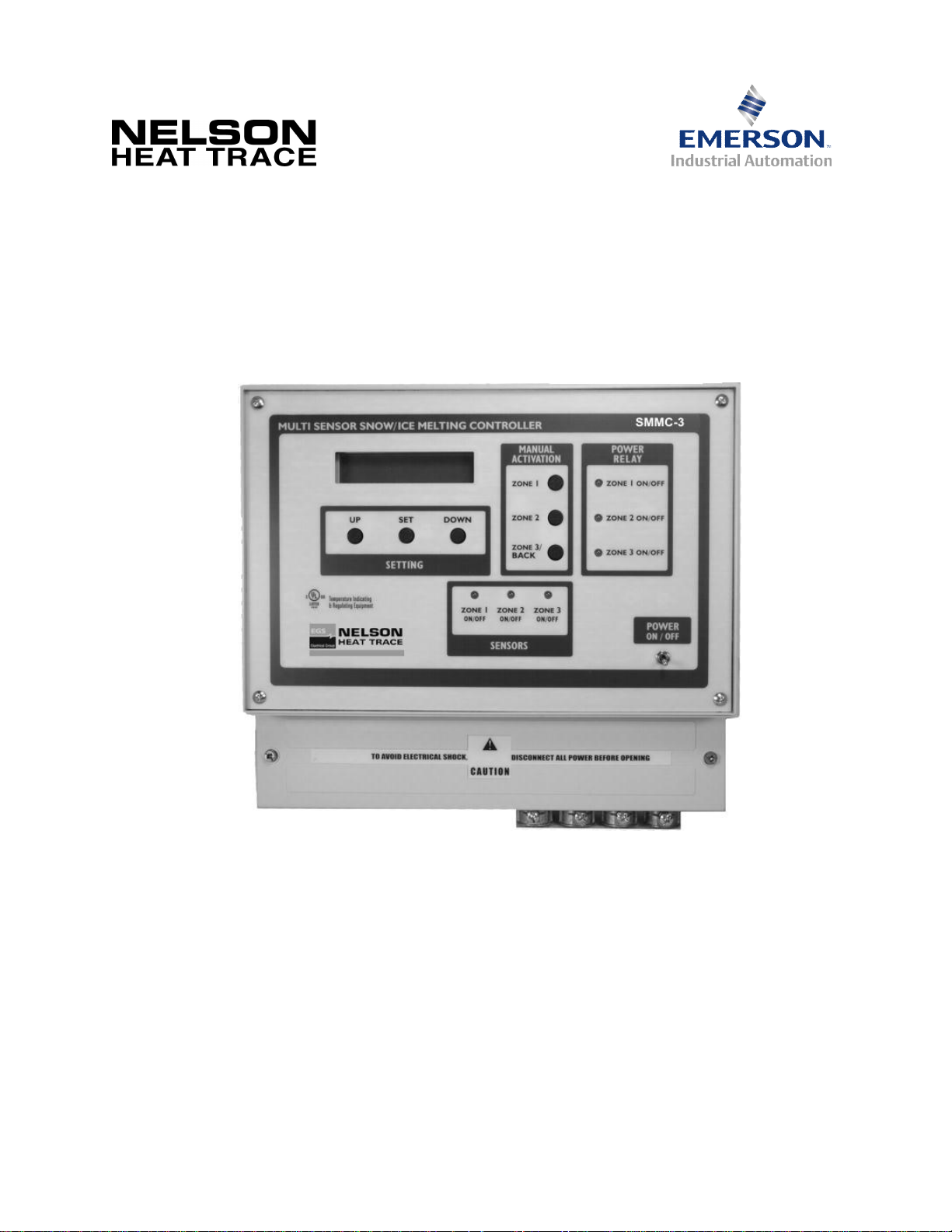
The SMMC-3 Control Panel manages snow and ice melting equipment for sidewalks, driveways, gutters, downspouts,
etc. Suitable for controlling all types of heating cable systems, the SMMC-3 can monitor snow and ice accumulation in
three separate zones. The SMMC-3 programming allows each zone to be controlled independently or on a priority mode
basis. In the priority mode, one zone can be given priority and the other zones cannot be energized until the melting/deicing in that zone is complete. This can reduce the loading on the system by ensuring that multiple zones are not
energized simultaneously. The SMMC-3’s program allows customization of the key elements necessary for intelligent
and efficient snow melting control.
The SMMC-3 can access information from three different types of moisture sensors – surface (SMPS-1), aerial (SMAS-
1) and gutter (SMGS-1) and one temperature sensor (SMTS-1). The surface, aerial and gutter sensors detect moisture
from snow, ice, sleet, etc. and send appropriate signals to the SMMC-3. Similarly, the temperature sensor sends
temperature data back to the SMMC-3. Independent temperature and moisture information is processed by the SMMC-3
to ensure that heating equipment will only be energized when precipitation occurs during freezing conditions. For each of
the SMMC-3 control zones, up to two individual moisture sensors can be connected. However, for each zone only one of
these may be a surface sensor. Each SMMC-3 must have a temperature sensor, SMTS-1, in order to function. A SMTS1 is included with each SMMC-3.
The SMMC-3 is housed in an enclosure suitable for commercial/industrial applications (NEMA 12) and features an LCD
display, programming and associated indicator lights for operation of each zone.
The SMMC-3 is powered by 120VAC; control relays provide a 120VAC output to operate external contactors.
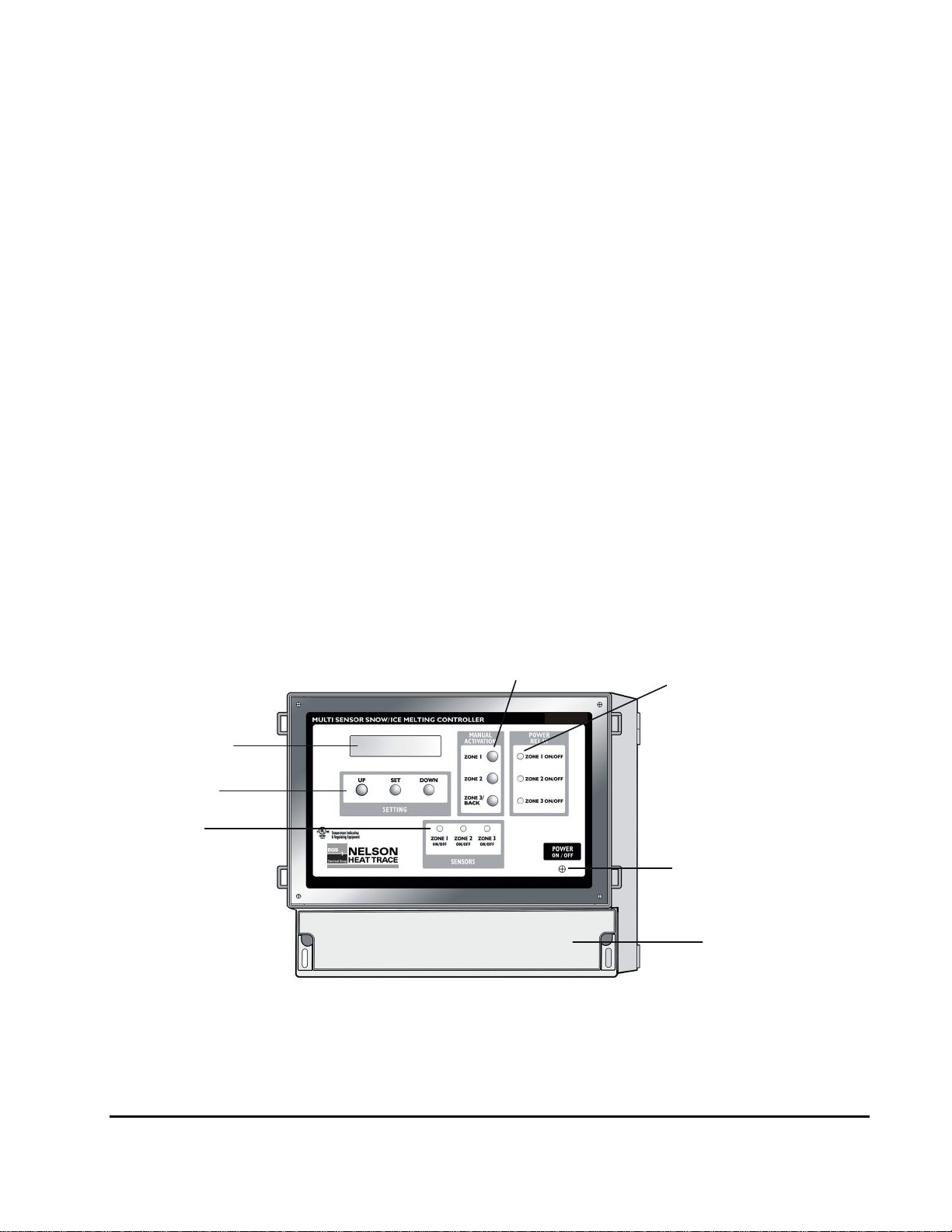
See Fig. 1 & 2.
PRE-PROGRAMMED CONFIGURATION
The SMMC-3 Control Panel is delivered preprogrammed for a single zone system, for use with either an aerial (SMAS-1)
or gutter (SMGS-1) sensor. (Note that the SMMC-3 does not distinguish between the gutter and aerial sensors). The deenergize temperature (the SMMC-3 will not energize the heating equipment when the ambient temperature is warmer
than this) is pre-set to 37°F (3°C), and relay hold time (the length of time that the heating equipment will stay energized
after it no longer senses the presence of ice/snow in the zone) is 3.0 hours. If the snow/ice melting system has been
designed to operate in this manner, then no programming is required: simply wire as per the following instructions.
Output Relay
Status Lights
(on when ZONE
heating is energized)
Fig.1
Control PanelSMMC-3
Buttons
SMMC-3
LCD
Programming
Buttons
Sensor Status
Lights
(on when ZONE
sensor is energized)
PO. Box 726 n TULSA, OK 74101 n TEL 918-627-5530 n FAX 918-641-7336 n www.nelsonheaters.com
ON/OFF
Access Cover
Switch
GA-2318, R1
Sheet 3 of 15
May 2008
Page 4
Installation & Operat ing Instructions
120 VAC, to contactor coils
power contactors(s)
C
-3
Fig.3
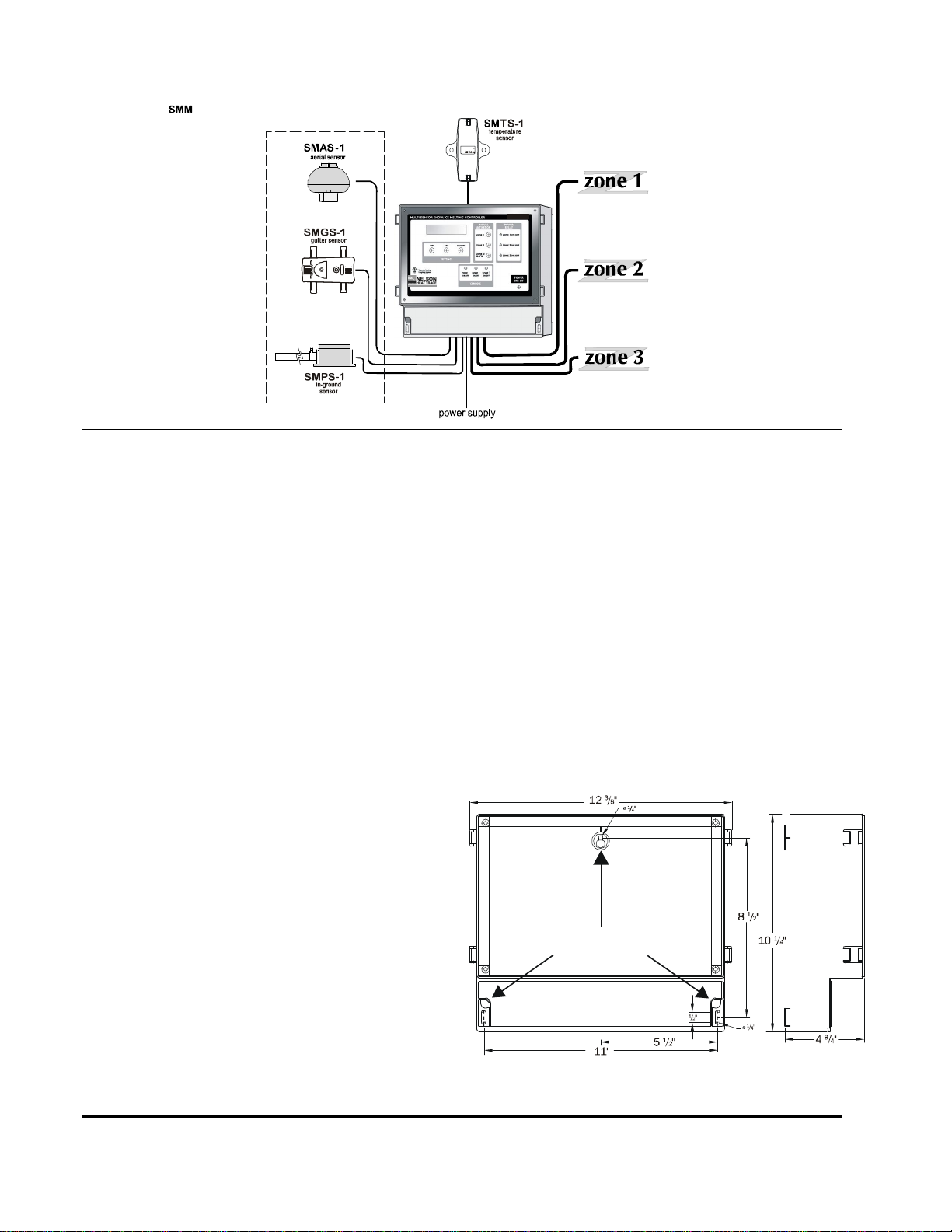
Mou n ting: m ou nts to wall via thr ee #10 screw s
mounting screw
Fi g.2
Sa mple Application Il lustrati on
snow/ice
sensor
options
maximum 2 sensors
per zone
WARN ING S
1. A qualified electrician must install the SMMC-3.
2. If after carefully reading these instructions you still
have questions regarding installation operation or
maintenance of this product, call the numbers listed
for assistance.
3. Prior to installation, check the SMMC-3 Control
Panel for possible shipping damage. Do not install a
damaged SMMC-3 Control Panel.
4. All heating equipment, controls & associated
systems must be installed in compliance with the
latest editions of all applicable electrical codes and
ordinances.
5. The SMMC-3 has been designed to accept only
Nelson moisture and temperature sensor inputs.
The risk of fire or electric shock exists if the SMMC3 is connected to any device other than a Nelson
sensor.
INSTA LL ATION
1. Mount the SMMC-3 securely to the wall with three
#10 screws, mount in an upright position in an indoor
location, in an area that is dry and not subject to
temperature extremes. See Fig. 3 for mounting
details.
2. Four ½” connectors have been installed on the
SMMC-3 Control Panel box to facilitate connection of
electrical conduit for input power supply wiring, and
contactor output wiring.
3. Remove the lower front access cover to begin
connecting wiring. On the back of the access cover is
a wiring guide label.
4. Connection to the SMMC-3 is done through terminal
blocks. Fish the wire being connected through the
adjacent knock-out, and pull out approximately 12” of
wire. The top half of the terminal block is removable
for easy wiring; gently pull up on the top half to
remove. After connecting the wire to the top half
gently set it back into the base while carefully pulling
back excess wire through the knock-out.
PO. Box 726 n TULSA, OK 74101 n TEL 918-627-5530 n FAX 918-641-7336 n www.nelsonheaters.com
GA-2318, R1
Sheet 4 of 15
May 2008
*
*maximum 1 SMPS-1 sensor per zone
SMMC-3
power contactors(s)
power contactors(s)
120 VAC, 450 VA
6. Do not connect heating equipment directly to the
SMMC-3 Control Panel. The SMMC-3 control relays
provide an output to operate external contactors. Each
output provides a maximum current output of 1.25A.
The risk of fire or electric shock exists if the heating
equipment is directly connected to the SMMC-3 Control
Panel.
7. These instructions must be saved and made available
to owners or users of this product and/or transferred to
future owners.
8. Secure the SMMC-3 in an accessible location. The
SMMC-3 Control Panel is not suitable for installation
environments subject to condensing moisture or those
exposed to temperature extremes.
9. Avoid shock or vibration.
locations
Page 5

5. The SMMC-3 terminal blocks serve 5 distinct connection sectors (see Fig 4), they are:
1. SMTS-1 – temperature sensor.
2. SMAS-1 aerial sensors / SMGS-1 gutter sensors (one each per zone).
3. SMPS-1 in-ground sensors (one each per zone).
4. Output to power contactors (one each per zone).
5. Control power input.
Connection to each sensor is described below:
6. The SMTS-1 is connected to the left-most terminal block, identified as TEMP. SENSOR. The SMMC-3 will not
function if the SMTS-1 wire color codes are not properly matched at the terminal block. See Fig. 4
7. The SMAS-1 or the SMGS-1 may be connected to any one of the 3 terminal blocks, identified as A/G. SENS. The
Zone number at the terminal block correlates to a snow-melting zone, ensure that the sensor is connected to the
proper zone terminal. The SMMC-3 will not function properly if the SMAS-1 / SMGS-1 wire color codes are not
properly matched at the terminal block. See Fig. 4
8. The SMPS-1 may be connected to any one of the 3 terminal blocks identified as PAV. SENS. The zone number at
the terminal block correlates to a snow-melting zone; ensure that the sensor is connected to the proper zone
terminal. The SMMC-3 will not function properly if the SMPS-1 wire color codes are not properly matched at the
terminal block. See Fig. 4
9. The outputs to the power contactors may be connected to any one of the 3 terminal blocks in the – OUTPUT TO
POWER CONTACTORS – segment, ZONE #1, 2 OR 3.
The Zone number at the terminal block correlates to a snow-melting zone; ensure that the output being connected
matches the sensor inputs connected. The output wire must be connected with the polarity as noted, ensure voltage
and amperages are suitable for the contactor being used. The SMMC-3 will not function properly if the output
connections are improperly made. See Fig. 4
10. The power supply is connected to the right-most terminal block, identified as POWER SUPPLY. The power supply
wires must be connected with the polarity as noted, ensure supply voltage is correct and noted ampacity is
available. The SMMC-3 will not function if the power supply connections are improperly made. See Fig. 4
11. At this point a quick check on the power supply wiring can be made. Energize the supply circuit for the SMMC-3
Control Panel, and turn on the SMMC-3 via the toggle switch, the LCD should illuminate at this point. Reattach the
front access cover; connection of the SMMC-3 is complete.
12. Each of the SMAS-1, SMGS-1 or SMPS-1 sensors connected to the SMMC-3 must be activated by programming
the SMMC-3; to do so, follow the steps in the programming section of this instruction.
PRE-PROGRAMMED CONNECTIONS
1. Remove lower access panel on the SMMC-3.
2. Connect the temperature sensor lead to the temperature sensor terminal block.
3. Connect the aerial or gutter sensor lead to the Zone 1 sensor terminal block.
4. Connect the control wire from the contactor coil to the Zone 1 output terminal block, 120VAC only. DO NOT
CONNECT OUTPUT DIRECTLY TO THE LOAD. THIS WILL DAMAGE THE SMMC-3 AND CAN RESULT IN
RISK OF INJURY OR FIRE.
5. Connect 120VAC to the power supply terminal block, verify polarity.
6. Turn on the power to the SMMC-3 using the toggle switch on the front panel.
7. System is now operational.
PO. Box 726 n TULSA, OK 74101 n TEL 918-627-5530 n FAX 918-641-7336 n www.nelsonheaters.com
GA-2318, R1
Sheet 5 of 15
May 2008
Page 6

Fig. 4 SMMC-3 Control Panel (Typical Connections)
L2
Sup
Connection Box
SMTS-1 SMAS-1/SMGS-1 SMPS-1 Contactor Output
SMAS-1 or SMGS-1
Sensor Wire
To Heater
Cables
SYSTEM CHEC K
Before you energize the controller, confirm :
· All the sensors, relay coils and the power supply
are connected to the proper terminal blocks.
· Only approved cable was used to extend the
sensors.
· The polarity of the 120 VAC power supply is
appropriate.
· You have connected the output terminals to a
relay or contactor coil, NOT DIRECTLY TO THE
HEATER LOAD.
After energizing the controller, you should see:
· The display lit and reading the temperature in
the area of the SMTS-1.
· The Small green LED’s next to the connected
terminal blocks are lit (no LED for the SMTS-1
block).
Control
Wiring
SMMC-3
Power
Input
L1
Heater Power
Contactor/
To cycle system and check sensor operation:
1. Submerge the SMTS-1 in a quart (litre) of water
and crushed ice.
2. After 20 minutes, confirm the display reads 32°F
(0°C).
3. Put a drop of water on each sensor surface*, the
Power Relay light(s) on the front panel will light
up and the associated output relay will energize.
4. Dry off the sensor surface; the relay output will
de-energize and the relay light will turn off after
the pre-set hold time.
* To confirm SMPS-1 operation, the slab
temperature must be below 59°F (15°C).
ply
PO. Box 726 n TULSA, OK 74101 n TEL 918-627-5530 n FAX 918-641-7336 n www.nelsonheaters.com
GA-2318, R1
Sheet 6 of 15
May 2008
Page 7

OP ERAT IO N
The SMMC-3 is a programmable controller, capable of controlling three separate snow/ice melting zones. A control relay
for each zone is included in the SMMC-3 to operate a contactor for each zone to energize the snow/ice melting
equipment. There are two operating mode selections possible with the SMMC-3:
MODE 1 – INDEPENDENT
In this mode each snow/ice melting zone is controlled independently. Mode 1 allows all 3 zones to be energized
simultaneously. This mode is best used where circuit loading is not a concern (e.g. adequate circuit ampacity is
available to operate the entire snow/ice melting load simultaneously).
MODE 2 – PRIORITY
In this mode each zone is controlled on a priority basis, with the most critical zone (always Zone 1) being melted first,
followed then by the less critical zones. Mode 2 allows only 1 of the zones to be energized at a time. This mode is best
used where circuit loading is a concern. A slight delay is provided when switching power between zones to ensure
circuits are not overloaded. Set-up in Mode 2 must be done either with Zones 1 & 2, (with Zone 3 not being used), or
Zones 1, 2 & 3. Operation is sequential, beginning with Zone 1. When Zone 1 is melted, the SMMC-3 de-energizes it
and then energizes Zone 2. However if snow/ice is detected on Zone 1, Zone 2 is de-energized and Zone 1 re-energized.
Similar logic applies for Zone 2 & 3; i.e. the lower numbered zone always takes priority.
The Priority mode available in the SMMC-3 can reduce circuit loading by splitting up a large snow melting area into
separate, smaller zones. For example, if a large area would require 90 Amps of current, this could be split into two
separate zones of, say, 50 Amps in one zone and 40 Amps in the other. Then, by programming the SMMC-3 in the
Priority Mode, only one zone will be enabled at any on time, resulting in a maximum circuit loading of 50 Amps.
Similarly, the area could be split into three zones of, say 25, 35 and 30 Amps; in this case circuit loading would be 35
Amps maximum. It should be further noted that when in Priority mode, the SMMC-3 always gives priority to Zone 1;
when Zone 1 is completely melted, then Zone 2 is enabled until melted, and then, finally Zone 3; i.e. Zone 1 always has
higher priority over Zone 2, which has higher priority over Zone 3. Further, if snow/ice is detected in a zone with higher
priority, then operation reverts to the zone with higher priority. For example, if melting has been completed in Zone 1,
and Zone 2 has been enabled, then if snow/ice is detected in Zone 1, operation in Zone 2 will be suspended, and Zone 1
will be re-enabled until melting is again complete, at which time melting in Zone 2 will recommence.
It is also important to give consideration to the assignment of zones; usually, high traffic areas will be given a high
priority, with lower traffic areas given lower priority. Zones can be easily reassigned at the terminals of the SMMC-3.
PO. Box 726 n TULSA, OK 74101 n TEL 918-627-5530 n FAX 918-641-7336 n www.nelsonheaters.com
GA-2318, R1
Sheet 7 of 15
May 2008
Page 8

ZONE ASSIGNMENT
M. Time Delay Zone 1
min.0 <2.0H> Max.10
(only sensors acti vated will sho w)
M1= Mo de 1 Ind epe nd ent
LCD Explanation
A1-A2-A3-P1-P2-P3-M1
The SMMC-3 uses the concept of a zone system to most
efficiently control snow/ice melting equipment. The term
“zone” means an area (either surface area or roof/gutter
area, or some combination of both) heated by a specific
set of snow/ice melting equipment that is controlled in a
common manner. The SMMC-3 allows for up to three
zones, and each zone can have multiple moisture sensors
for, say, roof/gutter, aerial and/or surface snow/ice
detection. If any one of the sensors detects moisture, the
heating equipment may be energized. The moisture
sensor in the zone should be generally, surrounded by the
heating equipment to ensure that the heating equipment is
only energized when there is snow/ice present in the zone.
Zones can be used to represent different areas; for
example a parking ramp area could be one zone while
roof/gutter de-icing on the same building could be another
zone. Similarly, two sidewalks on different sides of the
same building (possibly one on the north side and one on
the south side) could represent two separate zones. The
perimeter of a football stadium could be split into three
separate zones to reflect different weather conditions on
different sides of the building.
MANUAL OPERATION
The power to any one of the snow-melting zones may be
activated manually by pressing and holding the ZONE X
button until the information below appears on the LCD
screen. Manual activation will only work a long as the
ambient temperature is below the SMMC-3 shut-off
temperature. The duration of the time the zone will remain
energized (Time Delay) is pre-set to 2.0 hours; this can be
adjusted by following the programming instructions below.
The minimum and maximum settings possible are noted on
the LCD, adjustable in 0.5 hour increments.
Pressing UP increases the delay time.
Pressing DOWN decreases the delay time.
Press the SET button to accept the chosen delay time.
Once the delay time is set, the SMMC-3 returns to normal
control function, and energizes the heating equipment for
the selected zone.
To de-energize the manually activated heating
equipment, use the toggle switch on the front panel.
When operating in Mode 2 – Priority, the manual
override works as described if no snow melting zones
are energized. If any snow-melting zone is energized
the manual override only works to energize the higher
priority zone, thereby de-energizing the lower priority
zone.
It is important to note that manual operation is not
possible if the SMMC-3 has already energized the zone,
and that manual control will be overridden if the zone
moisture sensor detects precipitation.
Temperat ure
at SM TS -1 lo cation
Temperatu re
Valu e & U ni ts
°C o r ° F
Outside T=-3°C
(only sens ors act ivat ed will sho w)
A1= SMAS -1 o r S MGS-1 ZONE 1
A2= SMAS -1 o r S MGS-1 ZONE 2
A3= SMAS -1 o r S MGS-1 ZONE 3
P1= SMPS-1 ZON E 1
P2= SMPS-1 ZON E 2
P3= SMPS-1 ZON E 3
M2= Mo de 2 Pri ority
PO. Box 726 n TULSA, OK 74101 n TEL 918-627-5530 n FAX 918-641-7336 n www.nelsonheaters.com
GA-2318, R1
Sheet 8 of 15
May 2008
Page 9

PROGRAMMING INSTRUCTIONS
Level 2. Operating Mode Selection
2.Mode: 1 or 2
2. Mode No.2
<2zones> <3zones>
Level 3. Sensor Activation/De-activati on
3.Sensor Activation
1. Degree: °C or °F
<°C > <°F >
3.Sensor Activation
Yes <P.Zone3> No
2.Mode: 1 or 2
<No.1 > <No.2 >
Level 1. Temperature Unit Selection
The SMMC-3 program has been structured into 6 levels; within
each of these levels are further degrees of selection. Each
programming step is clearly described on the LCD, and easily
adjusted by the “UP”, “DOWN”, and “SET” buttons.
During programming:
· All regular operating functions of the SMMC-3 are
· If a button is not pressed for approximately 90
· Pressing the BACK button results in an exit from
Resetting to Factory Conditions
When the SMMC-3 is first energized, and during the time the initial
LCD display (SMMC Ver. X.X) screen shows push the UP and
DOWN buttons simultaneously to access the option to revert to
factory set conditions. Use the UP or DOWN button to select “yes”
or “no”; the program accepts the selection and returns to normal
operation.
To begin programming the SMMC-3 hold the SET button down for
5 seconds. The display will start in program level 1. To move to
other levels use the UP or DOWN buttons.
PROGRAM MODE
1. Degree: °C or °F
The default temperature units setting is °F.
To move to the next level use the UP or DOWN buttons.
Press the SET button to select the temperature display units.
Pressing UP selects Degrees C.
Pressing DOWN selects Degrees F.
After pressing the UP or DOWN button, the program automatically
accepts the selection and advances to the next program level.
suspended.
seconds, the program will return to normal
operation, saving programming changes made up to
the point exited.
the programming sequence, with the changes made
up to that point saved.
Pressing UP selects Mode 1 (Independent).
Pressing DOWN selects Mode 2 (Priority).
After pressing the UP button for Mode 1, the program
automatically accepts the selection and advances to the next
program level.
After pressing the DOWN button for Mode 2, the program
automatically accepts the selection and then moves to
another input screen, as shown below.
Pressing UP selects a 2 Zone system (Zone 1 & 2).
Pressing DOWN selects a 3 Zone system (Zone 1, 2 & 3).
After pressing the UP or DOWN button, the program
automatically accepts the selection and advances to the next
program level.
PROGRAM MODE
The default sensor activation setting is for an aerial (SMAS-
1), or gutter (SMGS-1) sensor, zone 1.
To move to the next level use the UP or DOWN buttons.
Press the SET button to begin the process to activate or
deactivate sensors. Each of the 3 control zones may have up
to 2 individual sensors, for a total of 6 sensors. <A/G.ZoneX>
refers to either an SMAS-1 or SMGS-1 sensor, <P.ZoneX>,
refers to an SMPS-1 in-ground sensor. The
activation/deactivation operation for all 6 sensors must be
stepped through before this operation is complete.
Yes <A/G.Zone1> No
3.Sensor Activation
Yes <A/G.Zone2> No
3.Sensor Activation
Yes <A/G.Zone3> No
PROGRAM MODE
The default mode setting is Mode 1.
To move to the next level use the UP or DOWN buttons.
Press the SET button to select the operating mode.
PO. Box 726 n TULSA, OK 74101 n TEL 918-627-5530 n FAX 918-641-7336 n www.nelsonheaters.com
Yes <P.Zone1> No
3.Sensor Activation
Yes <P.Zone2> No
3.Sensor Activation
3.Sensor Activation
GA-2318, R1
Sheet 9 of 15
May 2008
Page 10

Pressing UP activates the selected sensor.
Level 4. Ambient Off Temperature Setting
4.Ambient Off Temp.
min.34 <37°F> Max.50
Level 5. Slab Off Temperature Setting
5.Slab Off Temp.
min.41 <50°F> Max.68
Level 6. Setting the Relay Hold Time
6.Relay Hold Time Z1
min.0 <3.0H> Max.10
Outside T = 10°F
Pressing DOWN de-activates the selected sensor.
After pressing the UP or DOWN button for <P.Zone3>, the
program automatically accepts the selections and advances to the
next program level.
PROGRAM MODE
4.Ambient Off Temp.
The default ambient off temperature is 37°F (3°C).
To move to the next level use the UP or DOWN buttons.
Press the SET button to adjust the ambient off temperature, the
temperature above which the SMMC-3 will no longer energize the
heating equipment. The minimum and maximum settings possible
are noted on the LCD.
Pressing UP increases the degree setting.
Pressing DOWN decreases the degree setting.
Press the SET button to accept the chosen ambient off
temperature and advances to the next program level.
PROGRAM MODE
5.Slab Off Temp.
The default slab off temperature is 50°F (10°C).
To move to the next level use the UP or DOWN buttons.
Press the SET button to adjust the slab off temperature, the
temperature above which the SMMC-3 will de-energize the inground heating equipment. The minimum and maximum settings
possible are noted on the LCD.
Press the SET button to adjust the relay hold time for the
snow melting zones. The relay hold time is the amount of time
the snow melting zone remains energized after the moisture
sensor is dry. Each of the 3 zones is set independently, in 0.5
hour increments. The minimum and maximum settings
possible are noted on the LCD. The relay hold times for all 3
sensors must be stepped through before this operation is
complete.
min.0 <3.0H> Max.10
6.Relay Hold Time Z2
min.0 <3.0H> Max.10
6.Relay Hold Time Z3
Pressing UP increases the relay hold time.
Pressing DOWN decreases the relay hold time.
Press the SET button to accept the chosen relay hold time
and advance to the timing for the next zone.
After the hold time for Zone 3 has been set the program
automatically returns to programming Level #1 “Temperature
Unit Selection”. To exit the programming sequence and return
to normal control operation press the BACK button.
Temperature Stand-by
Whenever the ambient air temperature exceeds the ambient
off temp, the SMMC-3 goes into a “temperature stand-by”
mode, at which time all moisture sensors are de-activated. As
soon as the ambient air temperature drops below the ambient
off temp, the sensors are reactivated and operation begins as
normal.
Temperature Stand-by
Pressing UP increases the degree setting.
Pressing DOWN decreases the degree setting.
Press the SET button to accept the chosen slab off temperature
and advances to the next program level.
PROGRAM MODE
6.Relay Hold Time
The default relay hold time is 3.0 hours for all zones.
To move to the next level use the UP or DOWN buttons.
PO. Box 726 n TULSA, OK 74101 n TEL 918-627-5530 n FAX 918-641-7336 n www.nelsonheaters.com
GA-2318, R1
Sheet 10 of 15
May 2008
Page 11

Error M essages
SMTS-1 Error
The SMMC-3 will display an error message whenever a problem is
detected with the connection to the SMTS-1 or any of the SMPS1’s. Note that the connection status to a gutter (SMGS-1) or aerial
(SMAS-1) sensor is not monitored by the SMMC-3.
Manual only <M1>
Error!- SMTS-1 <cancel>
SMPS-1 Error
Error!- SMPS-1
<cancel>
The error screen will flash intermittently with the standard
operating screen. To cancel the error message press the
DOWN button when the error screen is showing.
If there is a SMTS-1 error all automatic operation of the
SMMC-3 ceases, however manual operation of each zone is
still possible.
If there is an SMPS-1 error, automatic control of the
associated zone is suspended, again manual operation is still
possible. Once the sensor problem has been fixed turn off the
power to the SMMC-3 Control Panel at the toggle switch,
reconnect the sensor wiring to the terminal block, then after a
minimum 10 seconds turn back on the power. The SMMC-3
program will recognize the sensor and begin normal
operation.
PO. Box 726 n TULSA, OK 74101 n TEL 918-627-5530 n FAX 918-641-7336 n www.nelsonheaters.com
GA-2318, R1
Sheet 11 of 15
May 2008
Page 12

TROU BLE SHOOTING GU ID E
SYMPTOMS PROBABLE CAUSE CORRECTION
System is not operating and system
light is not lit.
Display is not lit and power switch
is on.
System is not operating,
Temperature Standby on display.
Error! – SMTS-1 on display and
system not operating.
Error! – SMTS-1 on display after
corrections made.
Error! – SMPS-1 on display and
system not operating.
The aerial or gutter sensors are wet
(covered in snow), the LED above
the corresponding terminal block is
lit and the system is not heating.
The in-ground sensor is wet
(covered in snow), the sensor
surface is warm and system is not
heating.
No Power to SMMC-3 Turn on power using switch on front
panel.
Supply not energized or power
input fuse burned out.
Check power supply. If LED above
power input terminal connection is
not lit, replace fuse (4A spare fuse )
supplied with SMMC-3.
The SMMC-3 is in a standby mode,
NORMAL OPERATION
the ambient temperature outside is
above the programmed
temperature required to melt snow.
There is a communication problem
with the temperature sensor
Make sure the temperature sensor
lead wires are connected to the
terminal properly. If the sensor wire
has been extended, use 3
Conductor Instrumentation Cable,
#18AWG, unshielded, common
conductors such as twisted pair
communications wire, telephone
wire, electrical building wire and
doorbell wire is not acceptable.
Manufacturer: Belden #5301UE or
equal.
Need to clear SMTS-1 error from
SMMC-3 program.
Turn off system using the front
panel switch, wait 10 seconds and
turn on again. The SMMC-3 should
now recognize the sensor.
There is a communication problem
with the in-ground sensor.
Make sure the in-ground sensor
lead wires are connected to the
terminal properly. If the sensor wire
has been extended, use 4
Conductor Instrumentation Cable,
#18AWG, shielded, common
conductors such as twisted pair
communications wire, telephone
wire, electrical building wire and
doorbell wire is not acceptable.
Manufacturer: Belden #9418 or
equal.
Possible communication problem
with the aerial or gutter sensor. No
error message will show on the
display when this occurs.
Make sure the in-ground sensor
lead wires are connected to the
terminal properly. If the sensor wire
has been extended, use 3
Conductor Instrumentation Cable,
#18-20AWG, shielded or
unshielded, common conductors
such as twisted pair
communications wire, telephone
wire, electrical building wire and
doorbell wire is not acceptable.
Manufacturer: Belden #8770 or
equal.
The surface of the in-ground sensor
may be dirty, possibly covered with
sealant.
Clean the sensor surface to get rid
of any contaminant, use mild
detergent and carefully scrub with
steel wool.
PO. Box 726 n TULSA, OK 74101 n TEL 918-627-5530 n FAX 918-641-7336 n www.nelsonheaters.com
GA-2318, R1
Sheet 12 of 15
May 2008
Page 13

doors to sense air
SMMC-3 CONTROL PANEL (ACCESS COVER REMOVED)
SMTS-1
Zone 1 Sensor
Input SMAS-1 or
SMGS-1 (Default)
Zone 2 Sensor
Input SMAS-1 or
SMGS-1
Zone 3 Sensor
Input SMAS-1
or SMGS-1
Zone 1 Sensor
Input SMPS-1
(must be programmed
To activate)
Zone 2 Input
for SMPS-1
Zone 3 Input
for SMPS-1
Zone 1 Output
Terminal Block
Connector to
Contactor Coil
(Default)
Zone 2
Output
Fuse
“Fuse OK” LED
Zone 3
Output
120VAC Power Connection
Temperature
Sensor, SM TS-1:
this is included with
the SMMC-3 and
must be installed
out
temperature.
PO. Box 726 n TULSA, OK 74101 n TEL 918-627-5530 n FAX 918-641-7336 n www.nelsonheaters.com
Aerial Snow
Sensor, SM AS-1:
Mast mounted to
sense falling snow
(may be used as the
preprogrammed
sensor).
Gutter Sensor,
SMGS-1: secured in
the gutter to detect
moisture conditions
(may be used as the
preprogrammed
sensor).
In-Ground Sensor , SM PS-1:
installed in-ground to detect
moisture and slab temperature
(the SMMC-3 must be
programmed to recognize this
sensor, refer to the instruction
manual for details).
Wiring guide on
back of terminal
block cover
GA-2318, R1
Sheet 13 of 15
May 2008
Page 14

SP ECIFICATION S
Electrical
Power Requirements
120 VAC, 50/60 hz, 480VA
Control Relays – Outputs
120 VAC, Pilot Duty, 120VA
Power Supply – Sensors
24 VAC, Class 3, 12VA
Temperature Sensor Supply
5 VDC, Class 2, 0.5VA
SENSOR EXTENSION WIRE SPECIFICATIONS
Aerial Sensor SMAS-1
3 Conductor Instrumentation Cable, #18-20AWG, shielded or unshielded,
common conductors such as twisted pair communications wire, telephone wire,
electrical building wire and doorbell wire is not acceptable.
Manufacturer: Belden #8770 or equal
Gutter Sensor SMGS-1
3 Conductor Instrumentation Cable, #18-20AWG, shielded or unshielded,
common conductors such as twisted pair communications wire, telephone wire,
electrical building wire and doorbell wire is not acceptable.
Manufacturer: Belden #8770 or equal
Temperature Sensor SMTS-1
3 Conductor Instrumentation Cable, #18AWG, unshielded, common conductors
such as twisted pair communications wire, telephone wire, electrical building
wire and doorbell wire is not acceptable.
Manufacturer: Belden #5301UE or equal
Pavement Sensor SMPS-1
4 Conductor Instrumentation Cable, #18AWG, shielded, common conductors
such as twisted pair communications wire, telephone wire, electrical building
wire and doorbell wire is not acceptable.
Manufacturer: Belden #9418 or equal
Mechanical
NEMA 12 non-metallic enclosure
System Mem ory
Non-Volatile: no data loss
with a loss of system power
Dimensions
12.375” W x 10.25” H x 4.75” D
Certification
Environm ental Specifications
Ambient Operating Temperature Range
-4°F to 160°F / -20°C to 70°C
Storage Temperature
-4°F to 185°F / -20°C to 85°C
Relative Humidity
0 to 90% RH, non condensing
PO. Box 726 n TULSA, OK 74101 n TEL 918-627-5530 n FAX 918-641-7336 n www.nelsonheaters.com
GA-2318, R1
Sheet 14 of 15
May 2008
Page 15

LIMI TE D WARR AN TY AND LIABILITY
Nelson warrants that if there are any defects in material or workmanship in any heating cable or accessory during the first year (two
years on MI or self regulating heaters) after the date of its purchase, we will provide new products to replace any defective items, or
we will refund the purchase price paid for the accessory or cable, not including any labor or other installation costs. As an alternate,
we may elect to repair the cable or accessory at our factory with all shipping and other removal costs borne by the purchaser.
We further warrant that any services performed for the Buyer hereunder will be performed in a good and skillful manner, based on our
understanding of pertinent technical data as of the date of performance of such services. Nelson’s sole responsibility and liability in
the event of any defect, error, omission, or failure in the services rendered hereunder shall be to provide corrected services of the type
provided for herein, designed to correct such defect, error, omissions, or failure, and in no event shall the Nelson’s liability with
respect to such warranty exceed the amount received by it from the Buyer on account of such services.
Our obligation to provide corrected services, new products, refund the purchase price, or perform the repair described above is
conditioned upon (a) the installation of the accessory or cable conforming to the specifications set forth in our installation instructions
and (b) the accessory or cable not having been damaged by mechanical or electrical activities unrelated to the operation of the
accessory or cable.
A refund of your purchase price, provision of replacement products the repair of the accessory or cable or provision of
corrected services as described above shall be your sole and exclusive remedy for a breach of this warranty. THESE ARE
THE SOLE AND EXCLUSIVE WARRANTIES GIVEN BY NELSON WITH RESPECT TO THE GOODS AND SERVICES AND ARE
IN LIEU OF AND EXCLUDE ALL OTHER WARRANTIES, EXPRESS OR IMPLIED, ARISING BY OPERATION OF LAW OR
OTHERWISE, INCLUDING WITHOUT LIMITATION, MERCHANTABILITY AND FITNESS FOR A PARTICULAR PURPOSE
WHETHER OR NOT THE PURPOSE OR USE HAS BEEN DISCLOSED TO NELSON IN SPECIFICATIONS, DRAWINGS OR
OTHERWISE, AND WHETHER OR NOT NELSON'S PRODUCTS ARE SPECIFICALLY DESIGNED AND/OR MANUFACTURED
BY NELSON FOR YOUR USE OR PURPOSE.
This warranty does not extend to any losses or damages due to misuse, accident, abuse, neglect, normal wear and tear, negligence
(other than Nelson's), unauthorized modification or alteration, use beyond rate capacity, or improper installation, maintenance or
application. To the extent that you or your agents has supplied specifications, information, representation of operating conditions or
other data to Nelson in the selection or design of the Goods and the preparation of Nelson’s quotation, and in the event that actual
operating conditions or other conditions differ from those represented by you, any warranties or other provisions contained herein
which are affected by such conditions shall be null and void.
If within thirty (30) days after your discovery of any warranty defects within the warranty period, you notify Nelson thereof in writing,
Nelson shall, at its option, repair, correct or replace F.O.B. point of manufacture, or refund the purchase price for, that portion of the
Goods found by Nelson to be defective. Failure by you to give such written notice within the applicable time period shall be deemed
an absolute and unconditional waiver of your claim for such defects. Goods repaired or replaced during the warranty period shall be
covered by the foregoing warranty for the remainder of the original warranty period or ninety (90) days from the date of shipment,
whichever is longer.
This limited warranty does not cover any costs relating to the repair or replacement of any accessory or cable at the
installation site. Our accessories and cables are not easily accessible. A failed accessory or cable usually cannot be easily
repaired. Replacement of a failed accessory or cable will require that the materials under which it is installed be removed to permit
replacement of the accessory or cable. We w ill not reimburse any costs relating to the repair or replacement of any accessory
or cable at the installation site.
IN NO EVENT, REGARDLESS OF THE FORM OF THE CLAIM OR CAUSE OF ACTION (WHETHER BASED IN CONTRACT,
INFRINGEMENT, NEGLIGENCE, STRICT LIABILITY, OTHER TORT OR OTHERWISE), SHALL NELSON’S LIABILITY TO YOU
AND/OR YOUR CUSTOMERS EXCEED THE PRICE PAID BY YOU FOR THE SPECIFIC GOODS PROVIDED BY NELSON
GIVING RISE TO THE CLAIM OR CAUSE OF ACTION. YOU AGREE THAT WE SHALL NOT BE LIABLE TO YOU OR YOUR
CUSTOMERS FOR ANY INCIDENTAL, SPECIAL OR CONSEQUENTIAL OR PUNITIVE DAMAGES. No agent, employee or
representative of ours has authority to bind us to any affirmation, representation or w arranty concerning the goods sold
unless such affirmation, representation or warranty is specifically incorporated by w ritten agreement.
To obtain new products, arrange repair of existing product, or a refund under this warranty, please contact Nelson with a description
of the defect and proof of purchase at the addresses noted herein.
PO. Box 726 n TULSA, OK 74101 n TEL 918-627-5530 n FAX 918-641-7336 n www.nelsonheaters.com
ÓCopyright 2008 GA-2318, R1
Sheet 15 of 15
May 2008
 Loading...