

Page 1
00809-0200-4410, Rev BA
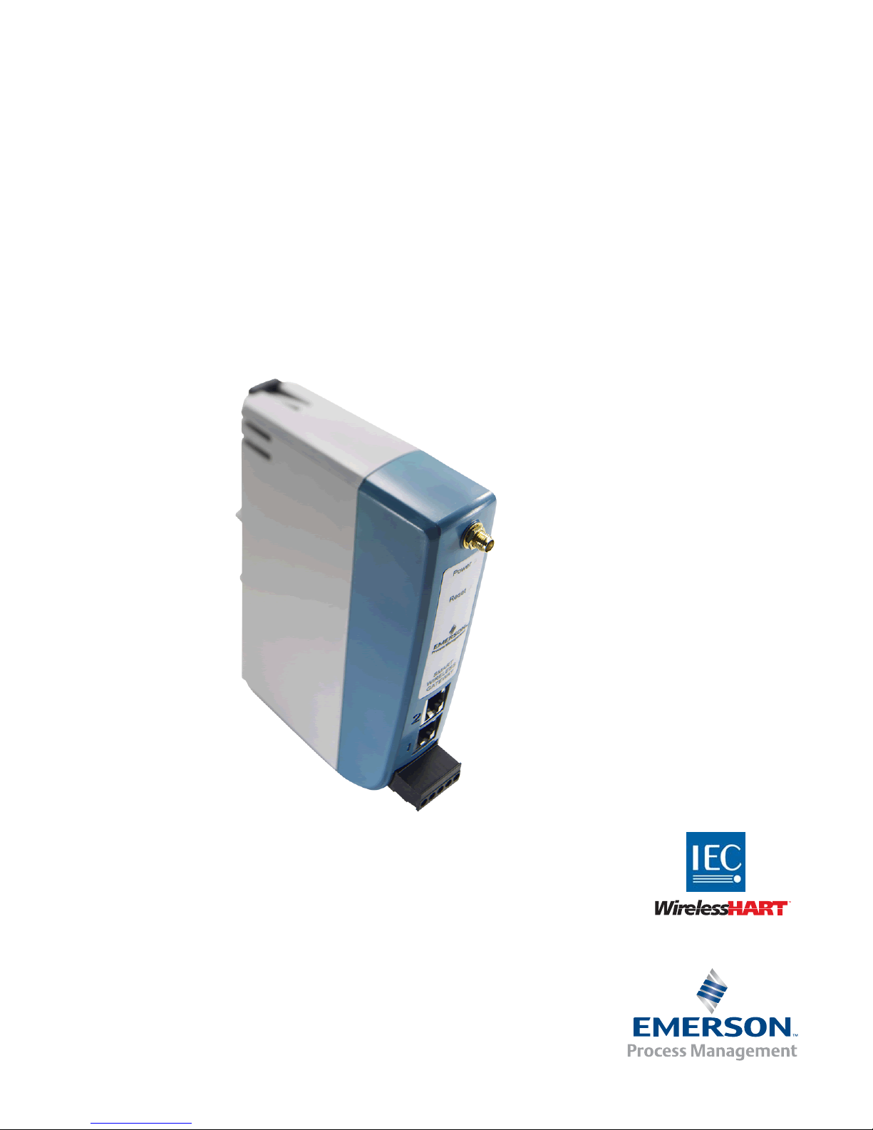
Emerson Smart Wireless Gateway 1410
Reference Manual
February 2014
Page 2

Page 3

Reference Manual
NOTICE
00809-0200-4410, Rev BA
Smart Wireless Gateway
Title Page
February 2014
Read this manual before working with the product. For personal and system safety, and for
optimum product performance, make sure you thoroughly understand the contents before
installing, using, or maintaining this product.
Within the United States, Emerson Process Management has
two toll-free assistance numbers:
Global Service Center
Software and Integration Support
1-800-833-8314 (United States)
+63-2-702-1111 (International)
Customer Central
Technical support, quoting, and order-related questions.
1-800-999-9307 (7:00 am to 7:00 pm CST)
North American Response Center
Equipment service needs.
1-800-654-7768 (24 hours—includes Canada)
Outside of the United States, contact your local Emerson Process Management
representative.
The products described in this document are NOT designed for nuclear-qualified
applications. Using non-nuclear qualified products in applications that require
nuclear-qualified hardware or products may cause inaccurate readings.
For information on Rosemount nuclear-qualified products, contact your local Emerson
Process Management Sales Representative.
PlantWeb is a registered trademark of one of the Emerson Process Management group of companies.
Modbus is a registered trademark of Schneider Automation, Inc.
All other marks are the property of their respective owners.
iii
Page 4

Page 5

Reference Manual
00809-0200-4410, Rev BA
Contents
1Section 1: Overview
2Section 2: Initial connection
Table of Contents
February 2014
1.1 Safety messages. . . . . . . . . . . . . . . . . . . . . . . . . . . . . . . . . . . . . . . . . . . . . . . . . . . . . . . .1
1.2 Introduction . . . . . . . . . . . . . . . . . . . . . . . . . . . . . . . . . . . . . . . . . . . . . . . . . . . . . . . . . . .2
1.3 Manual . . . . . . . . . . . . . . . . . . . . . . . . . . . . . . . . . . . . . . . . . . . . . . . . . . . . . . . . . . . . . . . . 2
1.4 Service support. . . . . . . . . . . . . . . . . . . . . . . . . . . . . . . . . . . . . . . . . . . . . . . . . . . . . . . . .3
1.5 Return of materials . . . . . . . . . . . . . . . . . . . . . . . . . . . . . . . . . . . . . . . . . . . . . . . . . . . . . 3
1.6 Product recycling/disposal . . . . . . . . . . . . . . . . . . . . . . . . . . . . . . . . . . . . . . . . . . . . . . . 4
2.1 Overview . . . . . . . . . . . . . . . . . . . . . . . . . . . . . . . . . . . . . . . . . . . . . . . . . . . . . . . . . . . . . .5
2.2 System requirements . . . . . . . . . . . . . . . . . . . . . . . . . . . . . . . . . . . . . . . . . . . . . . . . . . .6
2.3 Initial connection and configuration . . . . . . . . . . . . . . . . . . . . . . . . . . . . . . . . . . . . . . 6
2.3.1 Prepare PC/Laptop . . . . . . . . . . . . . . . . . . . . . . . . . . . . . . . . . . . . . . . . . . . . . . . .6
2.3.2 Connections and power. . . . . . . . . . . . . . . . . . . . . . . . . . . . . . . . . . . . . . . . . . . .7
2.3.3 Configure the gateway . . . . . . . . . . . . . . . . . . . . . . . . . . . . . . . . . . . . . . . . . . . .9
2.3.4 System backup . . . . . . . . . . . . . . . . . . . . . . . . . . . . . . . . . . . . . . . . . . . . . . . . . .14
2.3.5 Web page usage . . . . . . . . . . . . . . . . . . . . . . . . . . . . . . . . . . . . . . . . . . . . . . . . .14
2.3.6 Resetting to factory defaults . . . . . . . . . . . . . . . . . . . . . . . . . . . . . . . . . . . . . .15
3Section 3: Mounting and connection
3.1 Overview . . . . . . . . . . . . . . . . . . . . . . . . . . . . . . . . . . . . . . . . . . . . . . . . . . . . . . . . . . . . .17
3.1.1 General considerations . . . . . . . . . . . . . . . . . . . . . . . . . . . . . . . . . . . . . . . . . . .17
3.1.2 Physical description . . . . . . . . . . . . . . . . . . . . . . . . . . . . . . . . . . . . . . . . . . . . . .18
3.2 Mounting . . . . . . . . . . . . . . . . . . . . . . . . . . . . . . . . . . . . . . . . . . . . . . . . . . . . . . . . . . . . .18
3.3 Remote antenna. . . . . . . . . . . . . . . . . . . . . . . . . . . . . . . . . . . . . . . . . . . . . . . . . . . . . . .20
3.4 Connections . . . . . . . . . . . . . . . . . . . . . . . . . . . . . . . . . . . . . . . . . . . . . . . . . . . . . . . . . .22
3.4.1 Grounding . . . . . . . . . . . . . . . . . . . . . . . . . . . . . . . . . . . . . . . . . . . . . . . . . . . . . .22
3.4.2 Ethernet . . . . . . . . . . . . . . . . . . . . . . . . . . . . . . . . . . . . . . . . . . . . . . . . . . . . . . . .22
3.4.3 RS-485. . . . . . . . . . . . . . . . . . . . . . . . . . . . . . . . . . . . . . . . . . . . . . . . . . . . . . . . . .23
3.4.4 Terminating resistors . . . . . . . . . . . . . . . . . . . . . . . . . . . . . . . . . . . . . . . . . . . . .24
3.4.5 Power . . . . . . . . . . . . . . . . . . . . . . . . . . . . . . . . . . . . . . . . . . . . . . . . . . . . . . . . . .25
Tab le of Co ntents
1
Page 6

Table of Contents
February 2014
Reference Manual
00809-0200-4410, Rev BA
4Section 4: Software setup
4.1 Overview . . . . . . . . . . . . . . . . . . . . . . . . . . . . . . . . . . . . . . . . . . . . . . . . . . . . . . . . . . . . .27
4.2 System requirements . . . . . . . . . . . . . . . . . . . . . . . . . . . . . . . . . . . . . . . . . . . . . . . . . .28
4.3 Software installation . . . . . . . . . . . . . . . . . . . . . . . . . . . . . . . . . . . . . . . . . . . . . . . . . . .29
4.4 Security setup utility . . . . . . . . . . . . . . . . . . . . . . . . . . . . . . . . . . . . . . . . . . . . . . . . . . .30
4.4.1 Setup . . . . . . . . . . . . . . . . . . . . . . . . . . . . . . . . . . . . . . . . . . . . . . . . . . . . . . . . . . .31
4.5 AMS Wireless Configurator . . . . . . . . . . . . . . . . . . . . . . . . . . . . . . . . . . . . . . . . . . . . .32
4.5.1 Setup . . . . . . . . . . . . . . . . . . . . . . . . . . . . . . . . . . . . . . . . . . . . . . . . . . . . . . . . . . .32
4.6 Licensing and credits . . . . . . . . . . . . . . . . . . . . . . . . . . . . . . . . . . . . . . . . . . . . . . . . . . .34
5Section 5: Host integration
5.1 Overview . . . . . . . . . . . . . . . . . . . . . . . . . . . . . . . . . . . . . . . . . . . . . . . . . . . . . . . . . . . . .35
5.2 Network architecture . . . . . . . . . . . . . . . . . . . . . . . . . . . . . . . . . . . . . . . . . . . . . . . . . .35
5.3 Internal firewall. . . . . . . . . . . . . . . . . . . . . . . . . . . . . . . . . . . . . . . . . . . . . . . . . . . . . . . .36
5.4 Modbus . . . . . . . . . . . . . . . . . . . . . . . . . . . . . . . . . . . . . . . . . . . . . . . . . . . . . . . . . . . . . .37
5.4.1 Communication settings . . . . . . . . . . . . . . . . . . . . . . . . . . . . . . . . . . . . . . . . . .37
5.4.2 Register mapping . . . . . . . . . . . . . . . . . . . . . . . . . . . . . . . . . . . . . . . . . . . . . . . .39
5.5 EtherNet/IP
™
. . . . . . . . . . . . . . . . . . . . . . . . . . . . . . . . . . . . . . . . . . . . . . . . . . . . . . . . . .44
6Section 6: Troubleshooting
7Section 7: Glossary
AAppendix A: Product specifications
A.1 Ordering information . . . . . . . . . . . . . . . . . . . . . . . . . . . . . . . . . . . . . . . . . . . . . . . . . .55
A.2 Functional specifications . . . . . . . . . . . . . . . . . . . . . . . . . . . . . . . . . . . . . . . . . . . . . . .57
A.3 Physical specifications. . . . . . . . . . . . . . . . . . . . . . . . . . . . . . . . . . . . . . . . . . . . . . . . . .58
A.4 Communication specifications . . . . . . . . . . . . . . . . . . . . . . . . . . . . . . . . . . . . . . . . . .58
A.5 Self-organizing network specifications . . . . . . . . . . . . . . . . . . . . . . . . . . . . . . . . . . .59
A.6 System security specifications. . . . . . . . . . . . . . . . . . . . . . . . . . . . . . . . . . . . . . . . . . .59
A.7 Dimensional drawings. . . . . . . . . . . . . . . . . . . . . . . . . . . . . . . . . . . . . . . . . . . . . . . . . .60
A.8 Accessories and spare parts . . . . . . . . . . . . . . . . . . . . . . . . . . . . . . . . . . . . . . . . . . . . .62
2
Table of Contents
Page 7

Reference Manual
00809-0200-4410, Rev BA
BAppendix B: Product Certifications
Table of Contents
February 2014
B.1 Approved Manufacturing Locations . . . . . . . . . . . . . . . . . . . . . . . . . . . . . . . . . . . . . .63
B.2 Telecommunications Compliance . . . . . . . . . . . . . . . . . . . . . . . . . . . . . . . . . . . . . . .63
B.3 FCC and IC . . . . . . . . . . . . . . . . . . . . . . . . . . . . . . . . . . . . . . . . . . . . . . . . . . . . . . . . . . . .63
B.4 European Directive Information . . . . . . . . . . . . . . . . . . . . . . . . . . . . . . . . . . . . . . . . .63
B.5 Ordinary Location Certification from FM Approvals . . . . . . . . . . . . . . . . . . . . . . . .63
B.6 Hazardous Locations Certifications . . . . . . . . . . . . . . . . . . . . . . . . . . . . . . . . . . . . . .64
Tab le of Co ntents
3
Page 8

Page 9
Reference Manual
00809-0200-4410, Rev BA
Section 1 Overview
Safety messages . . . . . . . . . . . . . . . . . . . . . . . . . . . . . . . . . . . . . . . . . . . . . . . . . . . . . . . . . . . . page 1
Introduction . . . . . . . . . . . . . . . . . . . . . . . . . . . . . . . . . . . . . . . . . . . . . . . . . . . . . . . . . . . . . . . . page 2
Manual . . . . . . . . . . . . . . . . . . . . . . . . . . . . . . . . . . . . . . . . . . . . . . . . . . . . . . . . . . . . . . . . . . . . page 2
Service support . . . . . . . . . . . . . . . . . . . . . . . . . . . . . . . . . . . . . . . . . . . . . . . . . . . . . . . . . . . . . page 3
Return of materials . . . . . . . . . . . . . . . . . . . . . . . . . . . . . . . . . . . . . . . . . . . . . . . . . . . . . . . . . . page 4
Product recycling/disposal . . . . . . . . . . . . . . . . . . . . . . . . . . . . . . . . . . . . . . . . . . . . . . . . . . . page 4
1.1 Safety messages
Instructions and procedures in this manual may require special precautions to ensure the safety
of the personnel performing the operations. Information that potentially raises safety issues is
indicated by a warning symbol ( ). Please refer to these safety messages before performing an
operation preceded by this symbol.
Section 1: Overview
February 2014
Failure to follow these installation guidelines could result in death or
serious injury.
Make sure only qualified personnel perform the installation.
Explosions could result in death or serious injury.
Verify that the operating atmosphere of the device is consistent with the appropriate
hazardous locations certifications.
Electrical shock could cause death or serious injury.
Use extreme caution when making contact with the leads and terminals.
Warning - Potential Electrostatic Charging Hazard
The 1410 enclosure is engineered polymer. Use care in handling and cleaning when in
explosive environments to avoid an electrostatic discharge.
Warning - Explosion Hazard
Do not make or break any connections to the 1410 while circuits are live unless area is
known to be non-hazardous.
Overview
1
Page 10

Section 1: Overview
February 2014
1.2 Introduction
The Emerson Smart Wireless Gateway 1410 (Gateway) connects WirelessHART™ self-organizing networks with host systems and data applications. Modbus communications over RS-485 or
Ethernet provide universal integration and system interoperability. The optional OPC or
EtherNet/IP functionality from the Gateway offers a means to connect to newer systems and
applications while providing a richer set of data.
The Smart Wireless Gateway provides industry leading security, scalability, and data reliability.
Layered security ensures that the network stays protected. Additional devices can be added at
any time. There is no need to configure communication paths because the Gateway manages
the network automatically. This feature also ensures that WirelessHART field devices have the
most reliable path to send data.
What is Included?
The box containing the Gateway will contain several items essential to the complete installation
and operation of the Gateway.
Smart Wireless Gateway
Quick Installation Guide
Software pack, 2 disk set
Informational side label for IP address
Basic antenna (if no remote antenna is required)
Terminal block (black)
Reference Manual
00809-0200-4410, Rev BA
If an optional remote antenna has been ordered, it will be in a separate box containing:
Remote mount antenna
Mounting hardware
Lightning arrestor
Cable (50/25 ft. (15,2/7,62 m) in length)
Coaxial sealant tape
Right angle SMA to N-Type adapter cable
1.3 Manual
This manual will help to install, configure, operate, and maintain the Gateway.
Section 1: Overview
This section introduces the product and describes what components may be found in the box. It
also includes details for services and support as well as return and disposal of the product.
Section 2: Initial connection
This section describes how to connect to the Gateway for the first time and what settings should
be configured before placing it on a live control network. It is important to note that some
Gateways are used in stand-alone applications and do not reside on a network. In these cases, it
is still important to configure the items outlined in this section.
2
Overview
Page 11

Reference Manual
00809-0200-4410, Rev BA
Section 1: Overview
February 2014
Section 3: Mounting and connection
This section describes how to properly mount the Gateway and make electrical connections,
including electrical wiring, grounding, and host system connections. This section also describes
how to mount the optional remote antenna.
Section 4: Software setup
This section describes the installation and setup of the optional software included with the
Smart Wireless Gateway. This software will aid in secure host integration as well as wireless field
device configuration.
Section 5: Host integration
This section describes how to connect the Gateway to a host system and integrate data
gathered from the field device network. It covers network architectures, security, and data
mapping.
Section 6: Troubleshooting
This section provides troubleshooting tips as well as information to contact technical support
over the phone or through email.
Section 7: Glossary
The glossary defines terms used throughout this manual or that appear in the web interface of
the Smart Wireless Gateway.
Appendix A: Product specifications and Appendix B: Product Certifications
The appendices provide additional and more specific information on a variety of subjects
including Product Specifications and Product Certifications.
1.4 Service support
Global Service Center
Software and Integration Support
United States 1 800 833 8314
International 63 2 702 1111
Customer Central
Technical Support, quoting, and order related questions
United States1 800 999 9307 (7:00 a.m. to 7:00 p.m. CST)
Asia Pacific 65 6777 8211
Europe/Middle East/ Africa 49 8153 9390
Overview
3
Page 12

Section 1: Overview
February 2014
1.5 Return of materials
To expedite the return process outside of North America, contact your Emerson Process
Management representative.
Within the United States, call the Emerson Process Management Response Center toll-free
number 1 800 654 7768. The center, which is available 24 hours a day, will assist you with any
needed information or materials.
The center will ask for product model and serial numbers, and will provide a Return Material
Authorization (RMA) number. The center will also ask for the process material to which the
product was last exposed.
Individuals who handle products exposed to a hazardous substance can avoid injury if they
are informed of, and understand, the hazard. If the product being returned was exposed to
a hazardous substance as defined by OSHA, a copy of the required Material Safety Data
Sheet (MSDS) for each hazardous substance identified must be included with the returned
goods.
Reference Manual
00809-0200-4410, Rev BA
1.6 Product recycling/disposal
Recycling of equipment and packaging should be taken into consideration and disposed of in
accordance with local and national legislation/regulations.
4
Overview
Page 13
Reference Manual
00809-0200-4410, Rev BA
Section 2 Initial connection
Overview . . . . . . . . . . . . . . . . . . . . . . . . . . . . . . . . . . . . . . . . . . . . . . . . . . . . . . . . . . . . . . . . . . page 5
System requirements . . . . . . . . . . . . . . . . . . . . . . . . . . . . . . . . . . . . . . . . . . . . . . . . . . . . . . . . page 6
Initial connection and configuration . . . . . . . . . . . . . . . . . . . . . . . . . . . . . . . . . . . . . . . . . . . page 6
Failure to follow these installation guidelines could result in death or serious injury:
Only qualified personnel should perform the installation
Explosions could result in death or serious injury.
Verify that the operating atmosphere of the gateway is consistent with the appropriate
hazardous locations certifications
Do not make or break connections to the 1410 while circuits are live unless the area is
know to be non-hazardous
Potential electrostatic charging hazard. Enclosure is a polymer, use care when handling
or cleaning
Electrical shock could cause death or serious injury.
Use extreme caution when making contact with the leads and terminals
This device complies with Part 15 of the FCC Rules. Operation is subject to the following
conditions: This device may not cause harmful interference. This device must accept any
interference received, including interference that may cause undesired operation.
This device must be installed to ensure a minimum antenna separation distance of 20 cm
from all persons.
Section 2: Initial Connection
February 2014
2.1 Overview
This section describes how to connect to the Gateway for the first time and what settings should
be configured before placing it on a live control network. It is important to note that some
Gateways are used in stand-alone applications and do not reside on a network. In these cases, it
is still important to configure the items outlined in this section.
Before the Gateway can be permanently mounted and connected to a live control network, it
needs to be configured with an IP address. This is done by forming a private network between
the Gateway and a PC/Laptop. The following items are required to complete this section:
Gateway
PC/Laptop
Ethernet Cable
24 VDC (nominal) power supply
5Initial Connection
Page 14

Section 2: Initial Connection
February 2014
2.2 System requirements
The following requirements apply to the PC/Laptop used to configure the Gateway. Additional
requirements may apply if using the Security Setup Utility or AMS Wireless Configurator. See
Section 4: Software setup on page 27 for more information.
Web browser applications
Microsoft Internet Explorer
®
6.0 - 10.0
Ethernet
10/100 base-TX Ethernet communication protocol
2.3 Initial connection and configuration
2.3.1 Prepare PC/laptop
The PC/Laptop will need to be configured to form a private network before communicating to
the Gateway. The network settings can be found in the control panel of the PC/Laptop running a
Microsoft platform based operating system. To configure these settings:
Reference Manual
00809-0200-4410, Rev BA
1. Find and open the Control Panel. (It is generally found from the Start Menu.)
2. Open Network Connections.
3. Select Local Area Connection.
4. Right click the mouse and select Properties from the list.
5. Select Internet Protocol (TCP/IP), and choose the Properties button.
6. From the General tab, select Use the following IP address button.
7. Set the IP Address to 192.168.1.12 and press the Ta b button.
8. A Subnet mask of 255.255.255.0 should fill in automatically.
9. Click OK to close the Internet Protocol (TCP/IP) window.
10. Click Close on the Local Area Connection window.
6
Initial Connection
Page 15
Reference Manual
00809-0200-4410, Rev BA
Section 2: Initial Connection
February 2014
Internet proxies will need to be disabled through the PC/Laptop’s default internet browser.
Disable the proxies with the following procedure:
1. Find and open the default internet browser.
2. Find the To ol s menu and select Internet Options.
3. From the Connections tab, click the LAN Settings button.
4. Under Proxy Server, the boxes for Automatically Detect Settings and Use a proxy server for
your LAN should be unchecked.
5. Click OK to close the Local Area Network (LAN) Settings window.
6. Click OK to close the Internet Options window.
The PC/Laptop is now set up to form a private network and to communicate with the Gateway.
Note
Connecting to the Gateway's secondary Ethernet port will require different network settings.
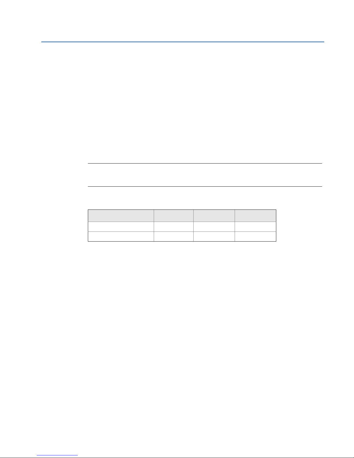
Please see Ta bl e 2 - 1 for additional network settings.
Table 2-1. Default IP Addresses
Gateway PC/laptop Subnet
Ethernet 1 192.168.1.10 192.168.1.12 255.255.255.0
Ethernet 2 192.168.2.10 192.168.2.12 255.255.255.0
2.3.2 Connections and power
Physically connect the PC/Laptop to the Gateway with an Ethernet cable by connecting one end
to the Ethernet port on the back of the PC/Laptop. Connect the other end to the Ethernet 1 port
on the Gateway. “Configure the gateway” on page 9 shows the standard terminal block
diagram. Once the Gateway and PC/Laptop are connected, wire a 24 VDC (nominal) power
supply with a capacity of at least 250 mA to the Gateway power input terminals.
Initial Connection
7
Page 16
Section 2: Initial Connection
+
-AB
24 VDC
(nominal)
Power Input
Serial
Modbus
S
Power
Reset
A
B
C
D
E
F
February 2014
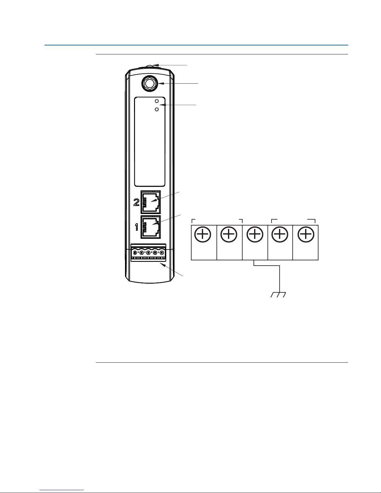
Figure 2-1. Emerson Smart Wireless Gateway 1410 Housing Diagram
Reference Manual
00809-0200-4410, Rev BA
A. DIN rail clip.
B. SMA connector.
C. Power and Reset indicator lights. During normal operation the power indicator will be green. During a reset
the reset light will turn red. The reset switch should not be enabled during normal operation.
D. Ethernet port 2. This secondary port must be enabled when ordering to access the device. When this port is
activated, the factory IP address is 192.168.2.10. See
E. Ethernet port 1. Use for standard communication to the webserver or other protocols enabled on the gateway.
The factory IP address is 192.168.1.10. See
F. Five screw terminal block.
Table 2-1.
Tab le 2 -1.
8
Initial Connection
Page 17
Reference Manual
00809-0200-4410, Rev BA
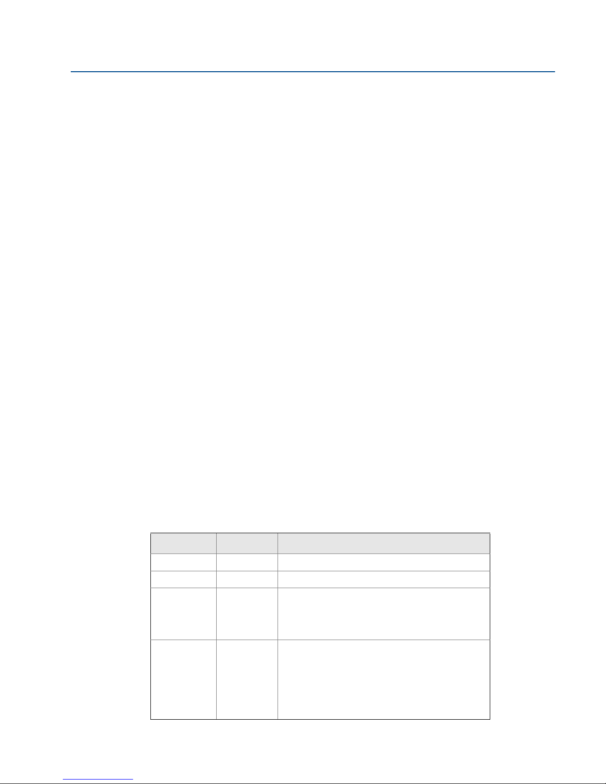
2.3.3 Configure the gateway
It is now possible to log into the Gateway for the first time and begin configuration for
placement on a live control network. The following items need to be configured:
Security Passwords
Time Settings
TCP/IP Network Settings
Use the following procedure to log in to the Gateway:
1. Open a standard web browser.
2. Enter https://192.168.1.10 in the address bar.
3. Continue though the security message.
4. Enter admin for User Name.
5. Enter default for the Password.
Section 2: Initial Connection
February 2014
The web browser will now be directed to the Gateway’s default home page. There is a navigation
menu located on the left hand side with four main areas.
Diagnostics: View status of communications, client server parameters, and more
Monitor: Screens created by the user to view data from field devices
Explorer: Basic view of values from field devices
Setup: Configure the Gateway for operations, security, and host system integration
Security passwords
There are four role based user accounts for the Gateway with varying levels of access. Ta b le 2 - 2
below describes this access.
Table 2-2. Role Based Access User Accounts
Role User name Web interface access
Executive exec Read-only access
Operator oper Read-only access
Maintenance maint Configure HART® device settings
Configure Modbus communications
Configure Modbus register mapping
Configure OPC browse tree
Configure Active Advertising
Administrator admin Includes all maintenance privileges
Initial Connection
Configure Ethernet network settings
Configure WirelessHART network settings
Set passwords
Set time settings
Set home page options
Configure custom point pages
Restart applications
9
Page 18

Section 2: Initial Connection
February 2014
Each of the initial passwords for the user accounts is default. It is recommended, for security
purposes, that these passwords are changed. The administrator password should be
appropriately noted when changed. If it is lost, do not return the Gateway to the factory, see
“Resetting to factory defaults” on page 15.
To change the User Accounts Passwords:
1. Navigate to Setup>Security>User accounts.
2. Set the new password for each role based user account, and confirm.
3. Choose Submit.
Note
It is suggested that the default security settings in Setup>Security>User Options be changed to
the local IT best practices or the “Normal” setting after initial login. Strong or custom settings
are available for more robust passwords. For more information on this screen and others please
see the User Interface Terminology Guide (00809-0600-4420).
Antivirus
Reference Manual
00809-0200-4410, Rev BA
Antivirus and other software tools are not included in the Gateway firmware. These software
tools should be installed on any machine connected to the Gateway. Emerson bundles the latest
software patches into our standard Gateway firmware updates. These software patches are not
anti-malware or antivirus tools in any sense of the word, but do provide the latest in security
protection.
Password complexity
The browser front-end of the Gateway supports many customizable password rules
(Setup>Security>User Options). All of the following rules are customizable:
Minimum overall password length
Minimum lowercase character count
Minimum uppercase character count
Minimum digit count
Minimum symbol count
Idle session timeout time
Maximum session lifetime to force a user to re-enter their password
Minimum password lifetime to prevent a user from changing their password too often
Maximum password lifetime to periodically force a user to change their password.
Password failure limit at which point the account is locked and the user must wait for a
specified period of time prior to additional attempts to enter their password
Password failure lock to lock an account after a specified number of incorrect
passwords
Require a wait period after the specified number of incorrect passwords have been
entered
Password history depth to limit reuse of passwords
10
Initial Connection
Page 19

Reference Manual
00809-0200-4410, Rev BA
Section 2: Initial Connection
February 2014
Logging
The Gateway monitors many security events automatically. A complete list of events can be
viewed from the Log Settings (Setup>Log Settings) area in the Gateway interface. The Gateway
also supports the optional use of a Syslog server. This provides significant flexibility and allows
the user to determine how log messages are handled and how long logs are kept. It is possible
for the user to configure the Syslog server to issue automated alerts for various messages.
Time settings
The Gateway is the timekeeper for the WirelessHART network, so it is imperative that the
Gateway’s time is accurate for timestamp data to be meaningful. Time settings can be found by
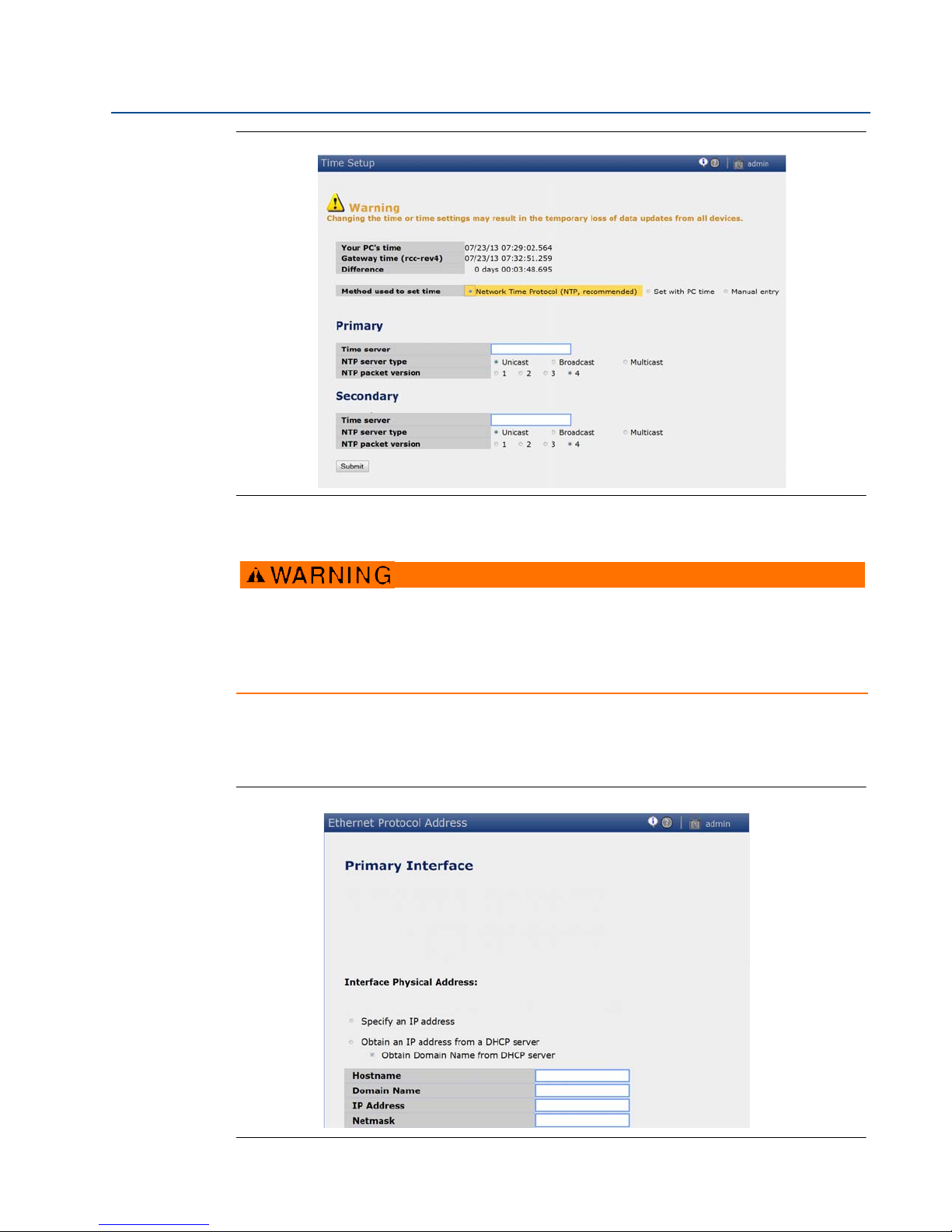
navigating to Setup>Time as shown in Figure 2-2 on page 12.
Gateway time settings and time stamps are stored internally as UTC time. The appropriate web
browser being used displays the time as per the local browser settings.
There are three ways to set the Gateway time:
1. Network Time Protocol (recommended).
This option uses a Network Time Protocol (NTP) server to slowly adjust the Gateway’s
time in order to match the time of the control network. Enter the IP address for the NTP
server and select the packet version (1, 2, 3, or 4).
2. Set with PC Time.
This option will match the Gateway’s time to that of the PC/Laptop.
3. Manual Entry.
This option allows the user to enter a specific date (MM:DD:YY) and time (HH:MM:SS).
Note
Network Time Protocol (NTP) is recommended for the best network performance because it
always adjusts time to match the network time server.
Failure to provide regular time synchronization over a long period of time (months) can cause
the Gateway network to drift off time.
Initial Connection
11
Page 20
Section 2: Initial Connection
February 2014
Figure 2-2. Setup>Time Settings
Reference Manual
00809-0200-4410, Rev BA
TCP/IP network settings
Use caution when making changes to the TCP/IP network settings. If they are lost or
entered incorrectly, the Gateway will require a factory reset (see“Resetting to factory
defaults” on page 15). Contact the network administrator for information on the proper
TCP/IP network settings to apply.
Prior to the Gateway being installed and connected to a live control network, it should be
configured with an IP address, as well as other TCP/IP network settings. This specific page can be
found in “System backup” on page 14.
Figure 2-3. Ethernet Settings
12
Initial Connection
Page 21

Reference Manual
00809-0200-4410, Rev BA
Section 2: Initial Connection
February 2014
Request the following configuration items from the network administrator:
Hostname
Domain Name
IP address
Netmask
Gateway
Obtaining an IP address from a DHCP server is not recommended, since the Gateway operation
will be dependent on the availability of the DHCP server. For maximum Gateway availability it is
best practice to specify an IP address.
To change the TCP/IP Network Settings:
1. Navigate to Setup>Ethernet protocol.
2. Select Specify an IP address (recommended).
3. Enter the following:
Hostname
Domain Name
IP Address
Netmask
Gateway
4. Choose Submit.
5. When prompted, choose Restart Apps.
6. Chose Yes to confirm restart.
7. Close the web browser.
Note
Once the IP Address of the Gateway has been changed, communications to the web interface
will be lost. Restart the web browser, then log back into the Gateway using the new IP address
and other TCP/IP network settings. The PC/Laptop TCP/IP network settings may need to be
changed. During a Restart Apps the wireless network will be temporarily lost.
Initial Connection
13
Page 22

Section 2: Initial Connection
February 2014
2.3.4 System backup
The Gateway has a System Backup and Restore feature that saves all user-configured data. It is
best practice that a System Backup be performed periodically throughout the installation and
configuration process.
1. Navigate to Setup>System Backup>Save.
2. Choose Save Configuration.
3. The Gateway collects the configuration date and when the file download pop up
appears, choose Save.
4. Enter a save location and file name.
5. Choose Save.
6. Choose Return to form.
Note
System backup contains user passwords and keys used for encrypting communication. Store
downloaded system backups in a secure location.
Reference Manual
00809-0200-4410, Rev BA
2.3.5 Web page usage
It is not recommended that users stay logged on to a single page or a large number of users on
multiple pages for long periods of time. This additional loading can slow the flow of data. The
Gateway by default logs users out who are logged on for long periods of time with no activity.
14
Initial Connection
Page 23

Reference Manual
00809-0200-4410, Rev BA
2.3.6 Resetting to factory defaults
In the event that the user name, password, or IP address of the Gateway is lost, the Gateway can
be restored to factory defaults by the procedure below.
Note
Following this procedure will cause the network to reform and all configuration parameters will
be reset to factory defaults. Once the Gateway is reset, the user is strongly recommended to
change the default password to maintain system security.
1. Turn off power to the Gateway, remove connectors, and un-mount the device from the
DIN rail.
2. Locate the Reset switch label on the back of the Gateway.
3. Break the label in the center and slide the switch up.
4. Mount and reconnect the Gateway; turn power ON on to the gateway.
5. Let the Gateway completely boot up (approximately 2 minutes). During this time the
red Reset light on the front of the unit will be ON.
Section 2: Initial Connection
February 2014
6. Turn off power to the Gateway, remove connectors and un-mount it from the rail again.
7. Return the Reset switch to lower position.
8. Mount and reconnect the Gateway; turn power ON on to the Gateway.
9. Verify the reset light is off, indicating the Reset switch is in the lower position. The
Gateway will now be programmed back to factory defaults including IP addresses. The
factory default IP addresses can be found in Table 2-1 on page 7
Initial Connection
15
Page 24

Page 25
Reference Manual
00809-0200-4410, Rev BA
Section 3: Mounting and connection
Section 3 Mounting and connection
Overview . . . . . . . . . . . . . . . . . . . . . . . . . . . . . . . . . . . . . . . . . . . . . . . . . . . . . . . . . . . . . . . . . . page 17
Mounting . . . . . . . . . . . . . . . . . . . . . . . . . . . . . . . . . . . . . . . . . . . . . . . . . . . . . . . . . . . . . . . . . . page 18
Remote antenna . . . . . . . . . . . . . . . . . . . . . . . . . . . . . . . . . . . . . . . . . . . . . . . . . . . . . . . . . . . . page 20
Connections . . . . . . . . . . . . . . . . . . . . . . . . . . . . . . . . . . . . . . . . . . . . . . . . . . . . . . . . . . . . . . . . page 22
Explosions could result in death or serious injury:
Verify that the operating atmosphere of the device is consistent with the appropriate
hazardous locations certifications.
Electrostatic discharge can damage electronics:
Use proper personal grounding before handling electronics or making contact with
leads and terminals
Electrical shock could cause death or serious injury. If the device is installed in a
high-voltage environment and a fault condition or installation error occurs, high voltage
may be present on transmitter leads and terminals.
Use extreme caution when making contact with the leads and terminals.
Failure to follow these installation guidelines could result in death or serious injury:
Make sure only qualified personnel perform the installation.
This device complies with Part 15 of the FCC Rules. Operation is subject to the following
conditions: This device may not cause harmful interference, this device must accept any
interference received, including interference that may cause undesired operation.
This device must be installed to ensure a minimum antenna separation distance of 20 cm
from all persons.
February 2014
3.1 Overview
This section describes how to properly mount the Gateway and make electrical connections,
including electrical wiring, grounding, and host system connections. This section also describes
how to mount the optional remote antenna.
3.1.1 General considerations
The unit itself is not designed for outdoor mounting without a suitable enclosure. The Gateway
should be mounted in an approved electrical enclosure or building.
The Gateway should be mounted in a location that allows convenient access to the host system
network (process control network) as well as the wireless field device network and protects the
Gateway from moisture and contamination.
Mounting and connection
17
Page 26
Section 3: Mounting and connection
February 2014
3.1.2 Physical description
The Gateway electronics is enclosed in a polymer housing. The front of the enclosure has
connections for power, Ethernet, and serial communications. The unit is designed to be
mounted on a DIN rail inside an electronic enclosure.
3.2 Mounting
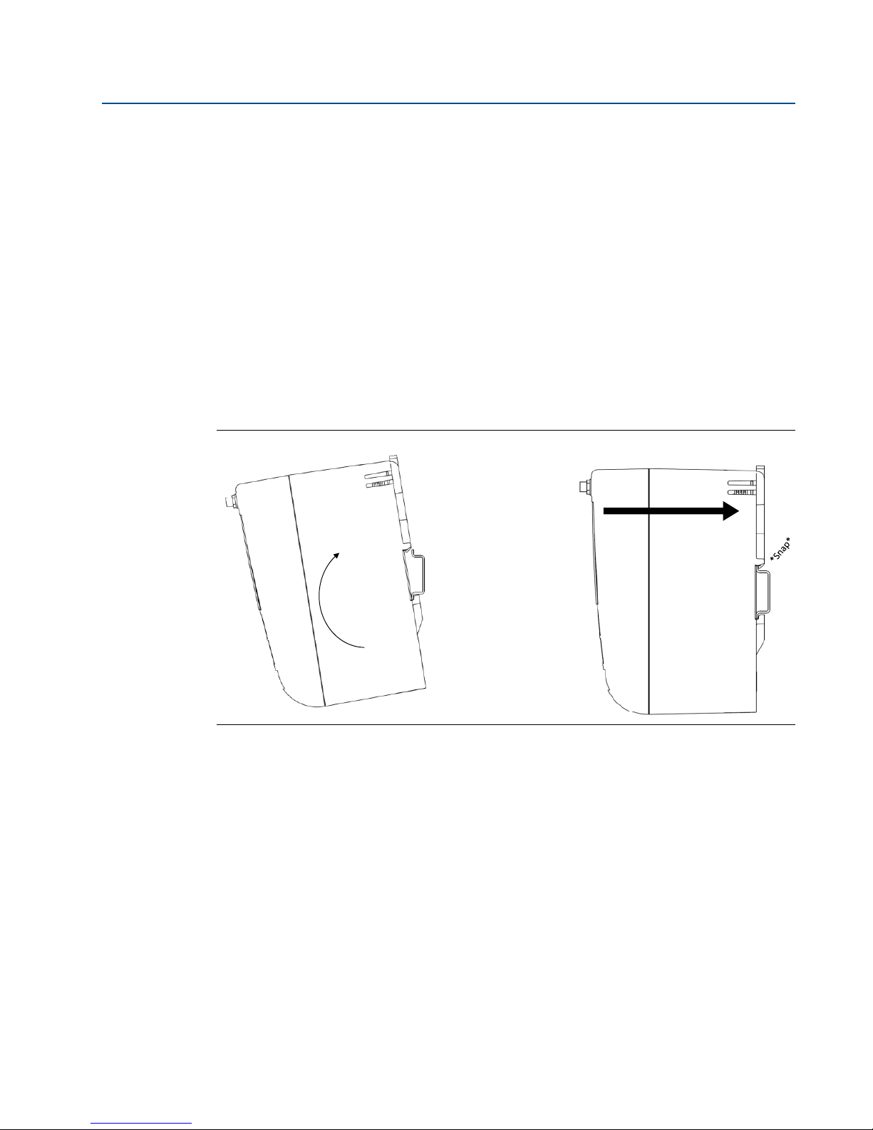
The unit can be snapped onto a DIN TS35/7.5 or TS35/15 rail system. To clip the unit onto the
DIN rail, see Figure 3-1.
1. Tilt the unit at a slight angle allowing the lower lip of the chassis to catch the bottom of
the DIN rail.
2. Apply pressure forward to snap the back of the unit securely onto the DIN rail.
Figure 3-1. Installing
Reference Manual
00809-0200-4410, Rev BA
18
Mounting and connection
Page 27
Reference Manual
NOTICE
Figure3Ͳ2Removing
00809-0200-4410, Rev BA
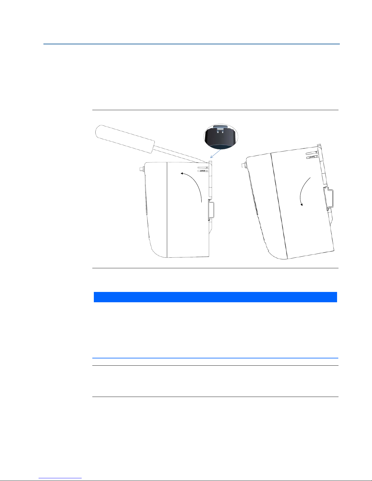
To remove the unit, see Figure 3-2.
1. Place a flat or rounded object (such as a screw driver) into the DIN clip and apply a slight
2. Once the unit is released from the DIN rail pull backwards and down to successfully
Figure 3-2. Removing
Section 3: Mounting and connection
February 2014
pressure downwards on the object.
disengage.
When mounting the unit in an electrical enclosure or other location, comply with the
appropriate local and governmental installation codes. Check to verify that the installer,
associated hardware, and installation equipment used have the proper certifications for the
specific type of installation being performed. Before installation, verify if local codes
require a permit and/or an inspection before energizing. When planning the installation,
account for routing the antenna cable within the enclosure.
Note
Do not mount the antenna within a metal enclosure. To avoid damage to sensitive RF
components do not remove protective cap from the Gateway SMA connector until ready to
install the antenna.
Mounting and connection
19
Page 28

Section 3: Mounting and connection
February 2014
3.3 Remote antenna
The small black flexible basic antenna supplied with the unit is for bench testing. In most
locations, a remote antenna is recommended for best range and performance. The remote
antenna options provide flexibility for mounting the Gateway based on wireless connectivity,
lightning protection, and current work practices.
Note
To avoid damage to sensitive RF components do not remove protective cap from the Gateway
SMA connector until ready to install the antenna.
When installing remote mount antennas for the Smart Wireless Gateway, always use
established safety procedures to avoid falling or contact with high-power electrical lines.
Install remote antenna components for the Smart Wireless Gateway in compliance with
local and national electrical codes and use best practices for lightning protection.
Before installing consult with the local area electrical inspector, electrical officer, and work
area supervisor.
The Smart Wireless Gateway remote antenna option is specifically engineered to provide
installation flexibility while optimizing wireless performance and local spectrum approvals.
To maintain wireless performance and avoid non-compliance with spectrum regulations,
do not change the length of cable or the antenna type.
If the supplied remote mount antenna kit is not installed per these instructions, Emerson
Process Management is not responsible for wireless performance or non-compliance with
spectrum regulations.
Reference Manual
00809-0200-4410, Rev BA
20
The remote antenna kit includes coaxial sealant for the cable connections, for the lightning
arrestor, and for the antenna.
Find a location where the remote antenna has optimal wireless performance. Ideally this will be
15-25 ft (4,6 - 7,6 m) above the ground or 6 ft (2 m) above obstructions or major infrastructure.
To install the remote antenna use one of the following procedures:
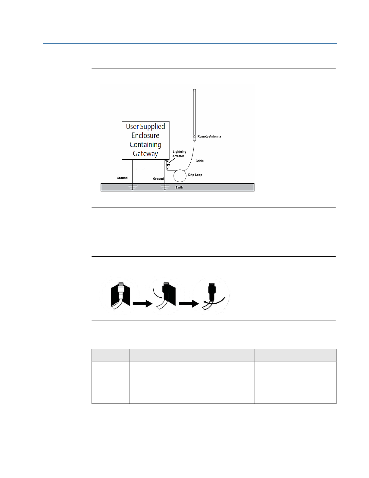
Installation of WL2/WN2 option:
1. Mount the antenna on a 1.5-2 inch pipe mast using the supplied mounting equipment.
2. Connect the lightning arrestor directly to the bottom of the user supplied enclosure.
3. Install the grounding lug, lock washer, and nut on top of the lightning arrestor.
4. Connect the antenna to the lightning arrestor using the supplied coaxial cable ensuring
the drip loop is not closer than 1 foot (0,3 m) from the lightning arrestor.
5. Use the coaxial sealant to seal each connection between the Gateway, lightning
arrestor, cable, and antenna.
6. Ensure that the mounting mast, lightning arrestor, and Gateway are grounded
according to local/national electrical code.
Mounting and connection
Page 29
Reference Manual
00809-0200-4410, Rev BA
Any spare lengths of coaxial cable should be placed in 1 foot (0,3 m) coils.
Figure 3-3. Installation of WL2/WN2 Option
Section 3: Mounting and connection
February 2014
Note: Weather proofing is required!
The remote mount antenna kit includes coaxial sealant for the cable connections for the
lightning arrestor, antenna, and Gateway. The coaxial sealant must be applied to guarantee
performance of the wireless field network. Please see Figure 3-4 for details on how to apply
weather proofing.
Figure 3-4. Applying coaxial sealant to cable connections
Table 3-1. Remote Antenna Kit Options
Kit option Antenna Cable 1 Lightning arrestor
WL2
WN2
1
/2 Wavelength Dipole
Omni-Directional
+6 dB Gain
1
/2 Wavelength Dipole
Omni-Directional
+8 dB Gain
50 ft. (15,2 m) LMR-400 Head mount, jack to plug
Gas discharge tube
0.5 dB insertion loss
25 ft. (7,6 m) LMR-400 Head mount, jack to plug
Gas discharge tube
0.5 dB insertion loss
Mounting and connection
21
Page 30

Section 3: Mounting and connection
February 2014
3.4 Connections
3.4.1 Grounding
The DIN rail should always be grounded in accordance with national and local electrical codes.
The most effective grounding method is a direct connection to earth ground with minimal
impedance. Grounding to the Gateway is accomplished through the DIN rail clip on the back of
the Gateway.
3.4.2 Ethernet
The Gateway is equipped with two 10/100 base-TX Ethernet communications ports (see Figure
3-5 on page 23). These connections can be used to access the Gateway’s web interface and to
communicate Modbus TCP, OPC, and EtherNet/IP protocols.
The primary Ethernet port (Ethernet 1) is used to connect to the host system or other
application systems. The secondary Ethernet port (Ethernet 2) can be used as a back up
connection or a maintenance port for local access to the Gateway.
Reference Manual
00809-0200-4410, Rev BA
Note
Unless dual Ethernet ports were specified at the time of order, the secondary Ethernet port
(Ethernet 2) will not be active.
22
Mounting and connection
Page 31
Reference Manual
00809-0200-4410, Rev BA
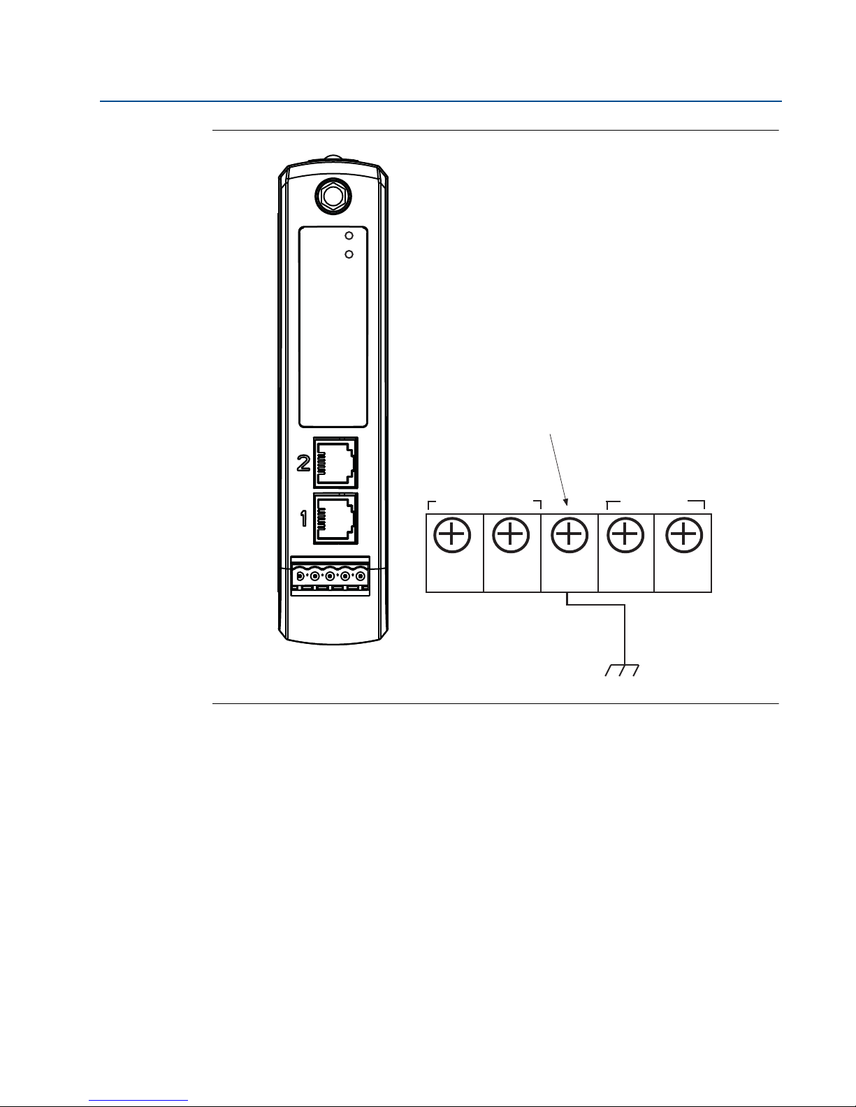
Figure 3-5. Emerson Smart Wireless Gateway 1410 Terminal Block Diagram
Section 3: Mounting and connection
February 2014
Power
Reset
A
A. 5 screw terminal block.
Ethernet connections should use Cat5e shielded cable to connect to an Ethernet hub, switch, or
router. The maximum cable length should not exceed 328 ft. (100 m).
3.4.3 RS-485
The Gateway can be ordered with an optional RS-485 (serial) connection (Figure 3-6 on
page 24). Modbus terminals are labeled A and B on the wiring diagram. This connection is used
to communicate Modbus RTU on an RS-485 data bus.
24 VDC
(nominal)
Power Input
+
-AB
Serial
Modbus
S
Use 18 AWG single twisted shielded pair wiring to connect the Gateway to the RS-485 data bus.
The total bus length should not exceed 4000 ft. (1220 m). Connect the Tx - (negative, receive)
wire to terminal A and the Rx + (positive, transmit) wire to terminal B. The wiring shield should
be trimmed close and insulated from touching the Gateway enclosure or other terminations.
If the existing data bus uses a 4 wire Full Duplex configuration, see Figure 3-6 to convert to a
2-wire Half Duplex configuration.
Mounting and connection
23
Page 32
Section 3: Mounting and connection
T
ON
K40
1
2
3
470Ω Pull-down Resistor
120Ω Terminating Resistor
470Ω Pull-up Resistor
DIP Switches*
February 2014
Figure 3-6. Convert from Full to Half Duplex
Tx
Rx
x
Rx
3.4.4 Terminating resistors
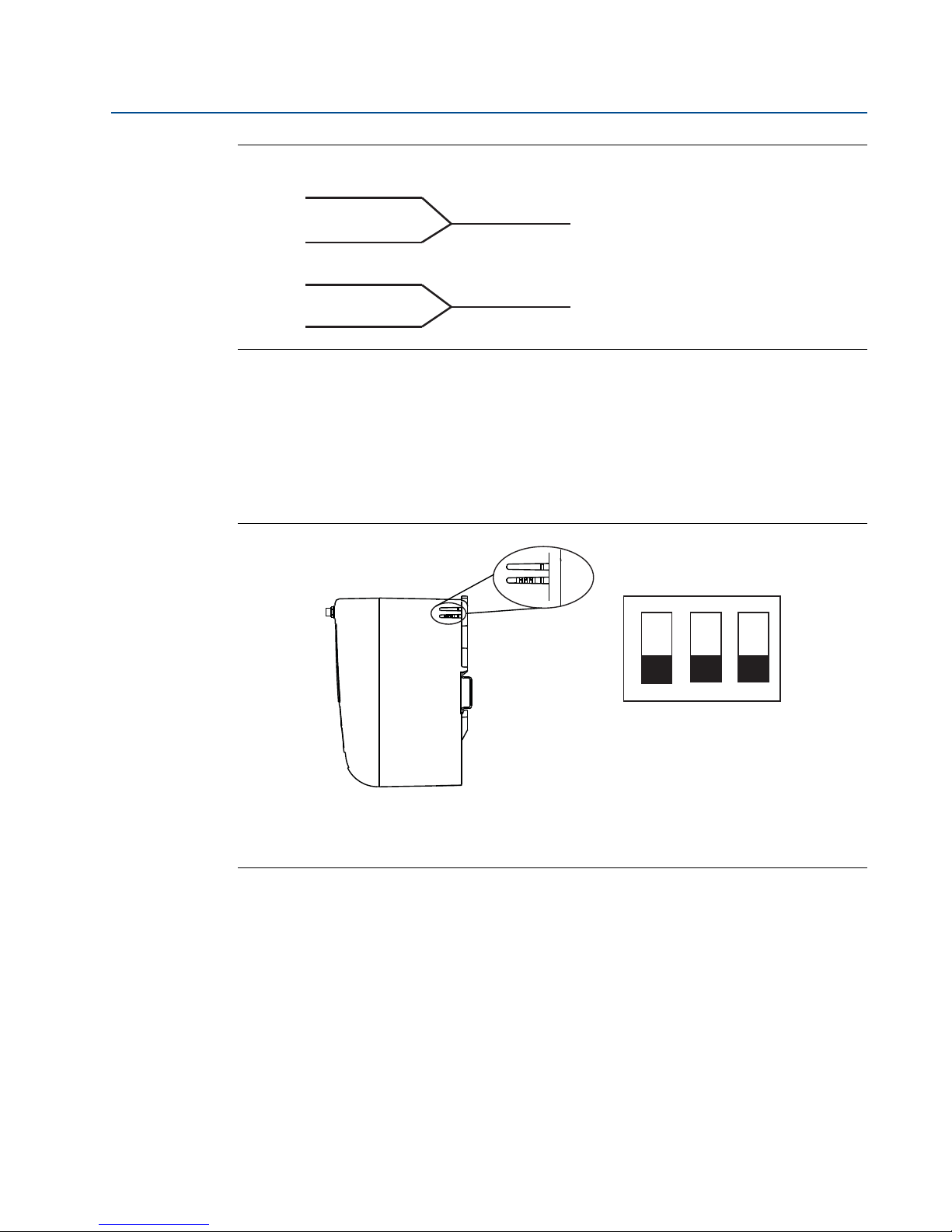
Three DIP switches are provided to enable various terminating resistors to the RS-485 data bus.
The switches are found inside the electronics housing, located behind an access slot on the
upper right side. The switches number bottom to top 1 through 3 and the upward position is
ON.
(A)
(B)
Reference Manual
00809-0200-4410, Rev BA
Figure 3-7. RS-485 Resistor DIP Switches
*Use a sharp non metal tool to switch between resistor options
Switches 1 and 3 are connected to pull-up and pull down resistors. Switch 1 is for the Tx (A) line
and Switch 3 is for the Rx (B) line. These 470 Ohm resistors are used to prevent noise from being
interpreted as valid communications during periods when no actual communications are
occurring. Only one set of pull-up and pull-down resistors should be active on the RS-485 data
bus at time.
Switch 2 is connected to a 120 Ohm terminating resistor. This resistor is used to dampen signal
reflections on long cable runs. RS-485 specifications indicate that the data bus should be
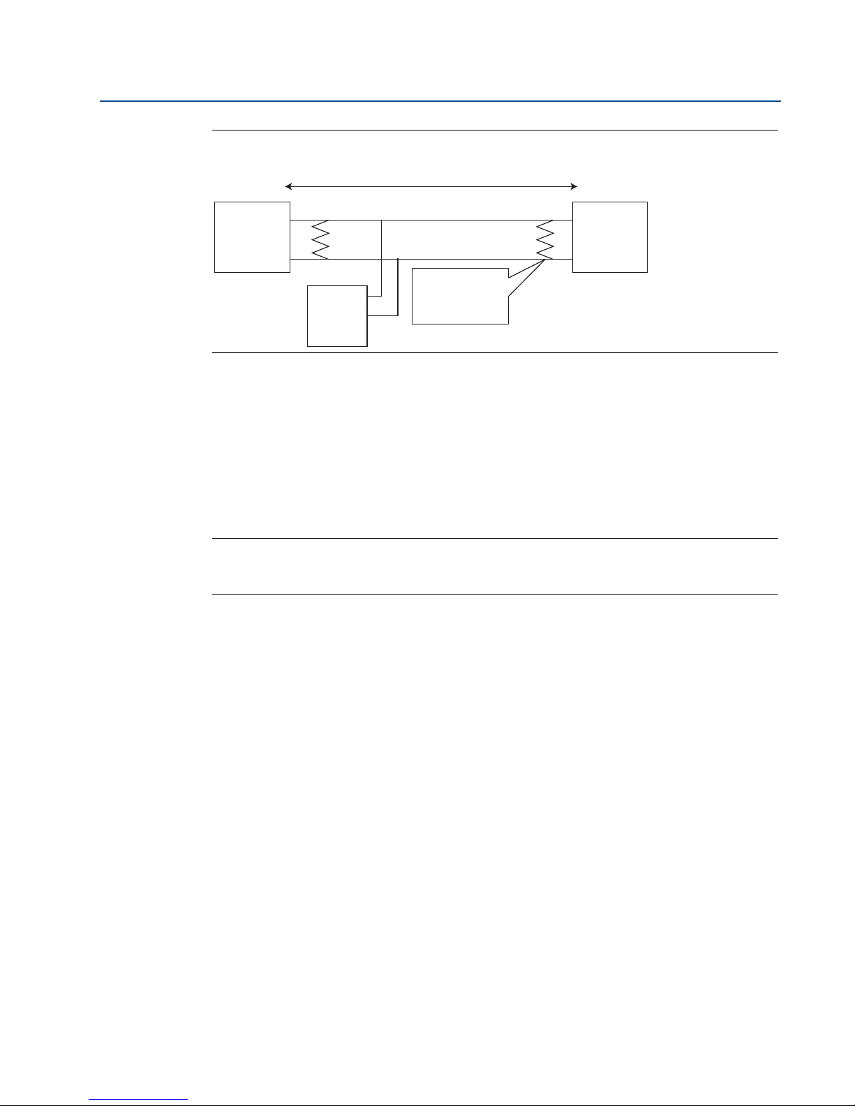
terminated at both ends (Figure 3-8). However termination should only be used with high data
rates (above 115 kbps) and long cable runs.
24
Mounting and connection
Page 33
Reference Manual
00809-0200-4410, Rev BA
Figure 3-8. Typical Half Duplex (2-wire) Network
Device 1
3.4.5 Power
The Gateway is designed to be powered by 24 VDC (nominal) Class 2 supply and requires 250
mA of current. The positive and negative connections are depicted on the diagram shown in
Figure 3-6 on page 24.
A
B
Device N
(up to 32
possible)
Up to 4000 ft. (1220 m)
Terminators required
only for high data rates
and long cable runs
Section 3: Mounting and connection
February 2014
Device 2
The wiring should include an external power shut-off switch or circuit breaker that is located
near the Gateway.
Note
Using an uninterruptible power supply (UPS) is recommended to ensure availability should there
be a loss of power.
Mounting and connection
25
Page 34

Page 35
Reference Manual
00809-0200-4410, Rev BA
Section 4 Software setup
Overview . . . . . . . . . . . . . . . . . . . . . . . . . . . . . . . . . . . . . . . . . . . . . . . . . . . . . . . . . . . . . . . . . . page 27
System requirements . . . . . . . . . . . . . . . . . . . . . . . . . . . . . . . . . . . . . . . . . . . . . . . . . . . . . . . . page 28
Software installation . . . . . . . . . . . . . . . . . . . . . . . . . . . . . . . . . . . . . . . . . . . . . . . . . . . . . . . . page 29
Security setup utility . . . . . . . . . . . . . . . . . . . . . . . . . . . . . . . . . . . . . . . . . . . . . . . . . . . . . . . . page 30
AMS Wireless Configurator . . . . . . . . . . . . . . . . . . . . . . . . . . . . . . . . . . . . . . . . . . . . . . . . . . . page 32
Licensing and credits . . . . . . . . . . . . . . . . . . . . . . . . . . . . . . . . . . . . . . . . . . . . . . . . . . . . . . . . page 34
4.1 Overview
This section discusses the installation and setup of the optional software included with the
Smart Wireless Gateway. This software is not required for the wireless field network to operate;
however, it will aid in secure host integration as well as wireless field device configuration. The
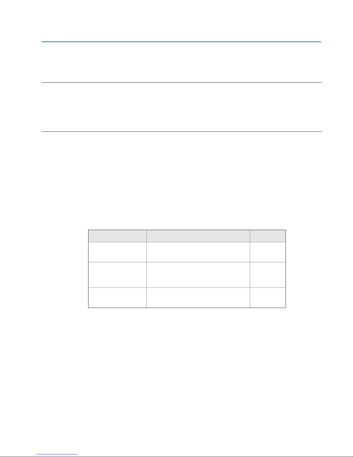
following table describes what items are installed and on which disk they can be found.
Section 4: Software Setup
February 2014
Table 4-1. Software Applications
Name Description Location
Security Setup Utility This utility allows the setup of SSL enabled
AMS Wireless
Configurator
Network
Configuration
communications between the Gateway and
host system.
This application allows complete
configuration of wireless field devices and
provides added security through drag and
drop provisioning.
This application configures AMS Wireless
Configurator to interface to a Wireless
Network or a HART Modem.
Disk 1
Disk 2
Disk 2
Additional system components may be installed depending on the current configuration of the
system.
Software setup
27
Page 36
Section 4: Software Setup
February 2014
4.2 System requirements
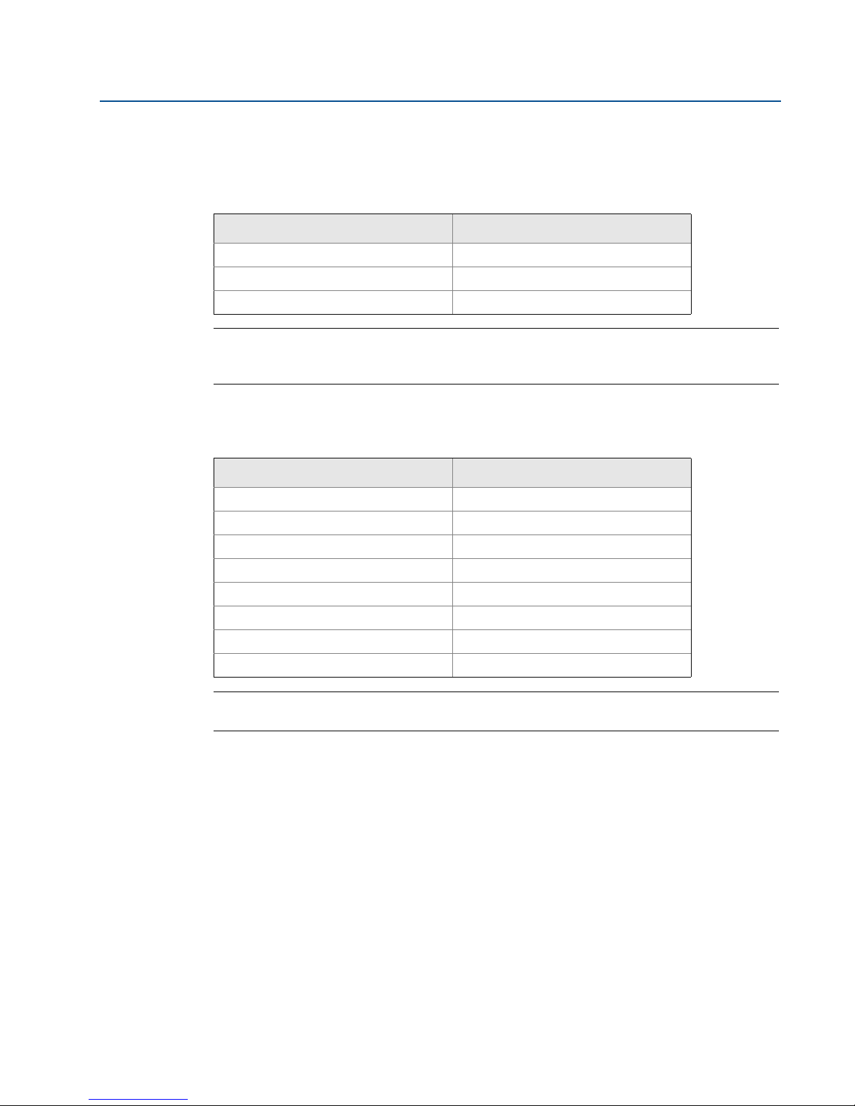
Table 4-2. PC Hardware
Minimum requirements Recommended requirements
Intel Core 2 Duo, 2.0 GHz Intel Core 2 Quad, 2.0 GHz or greater
1 GB Memory 3 GB Memory or Greater
1.5 GB free hard disk space 2 GB or more of free hard disk space
Note
Additional hard disk space is required for SNAP-ON applications. The minimum monitor
requirements are 1024 x 768 resolution and 16-bit color.
Table 4-3. Supported Operating Systems
Reference Manual
00809-0200-4410, Rev BA
Operating system Version
Windows XP Professional, Service Pack 3
Windows Server 2003 Standard, Service Pack 2
Windows Server 2003 R2 Standard, Service Pack 2
Windows Server 2008 Standard, Service Pack 2
Windows Server 2008 R2 Standard, Service Pack 1
Windows 7 Professional, Service Pack 1
Windows 7 Enterprise, Service Pack 1
Windows 8 Enterprise, Service Pack 1
Note
Only 32-bit versions of the operating systems are supported for AMS Wireless Configurator.
28
Software setup
Page 37

Reference Manual
00809-0200-4410, Rev BA
4.3 Software installation
The software can be found on the 2 disk pack, included with the Gateway. Depending on the PC
system configuration, installation may take 30-35 minutes. Installing disk one followed by disk
two is recommended. The Security Setup Utility is located on Disk 1. To install the software:
1. Exit/close all Windows programs, including any running in the background, such as
virus scan software.
2. Insert Disk 1 into the CD/DVD drive of the PC.
3. Follow the prompts.
AMS Wireless Configurator is located on Disk 2. To install the software:
1. Exit/close all Windows programs, including any running in the background, such as
virus scan software.
2. Insert Disk 2 into the CD/DVD drive of the PC.
Section 4: Software Setup
February 2014
3. Click Install from the menu when the AMS Wireless Configurator setup begins.
4. Follow the prompts.
5. Allow AMS Wireless Configurator to reboot PC.
6. Do not remove the disk from the CD/DVD drive.
7. Installation will resume automatically after login.
8. Follow the prompts.
Note
If the autorun function is disabled on the PC, or installation does not begin automatically,
double click D:\SETUP.EXE (where D is the CD/DVD drive on the PC) and click OK.
Software setup
29
Page 38
Section 4: Software Setup
February 2014
4.4 Security setup utility
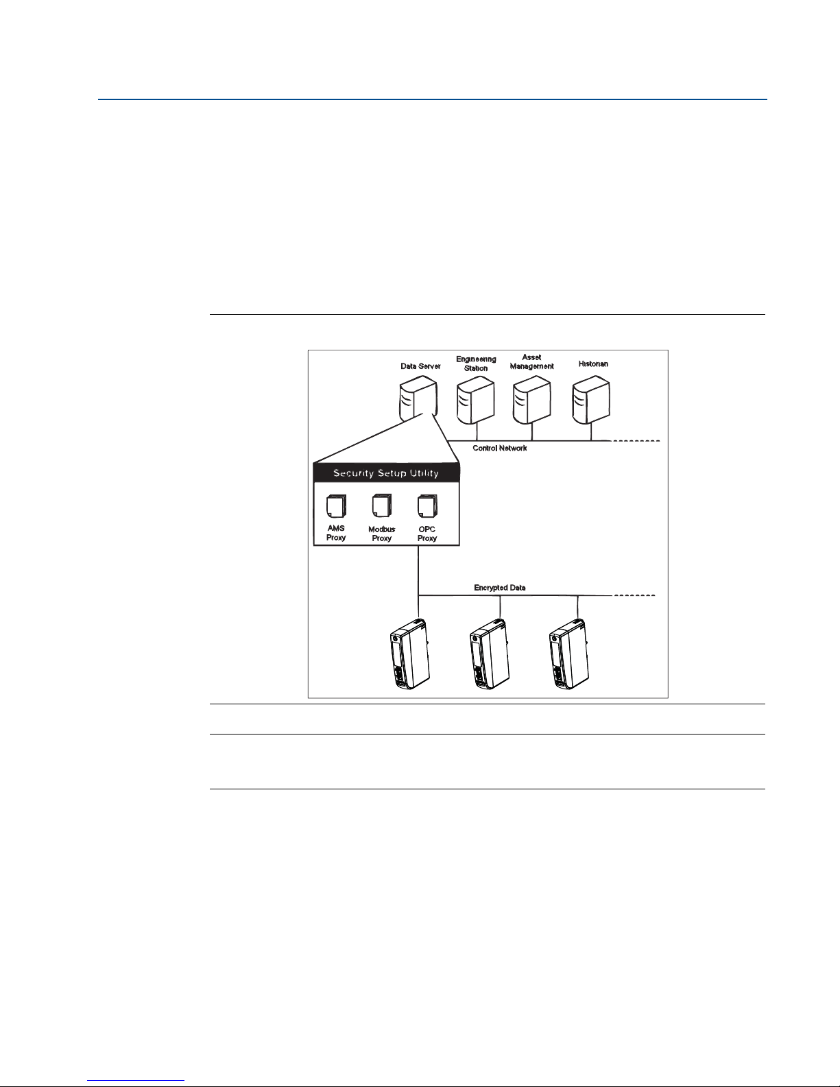
The Security Setup Utility enables secure communications between the Gateway and host
system, asset management software, data historians, or other applications. This is done by
encrypting the standard data protocols (AMS Wireless Configurator, Modbus TCP, and OPC)
used by the Gateway and making them available through various proxies within the Security
Setup Utility. These proxies can function as a data server for other applications on the control
network. The Security Setup Utility can support multiple Gateways at once and each proxy can
support multiple client application connects. Figure 4-1 shows a typical system architecture
using the Security Setup Utility.
Figure 4-1. Typical Host System Architecture Using Security Setup
Reference Manual
00809-0200-4410, Rev BA
Note
OPC communications requires the use of the Security Setup Utility regardless of whether
encryption is required.
30
Software setup
Page 39
Reference Manual
00809-0200-4410, Rev BA
4.4.1 Setup
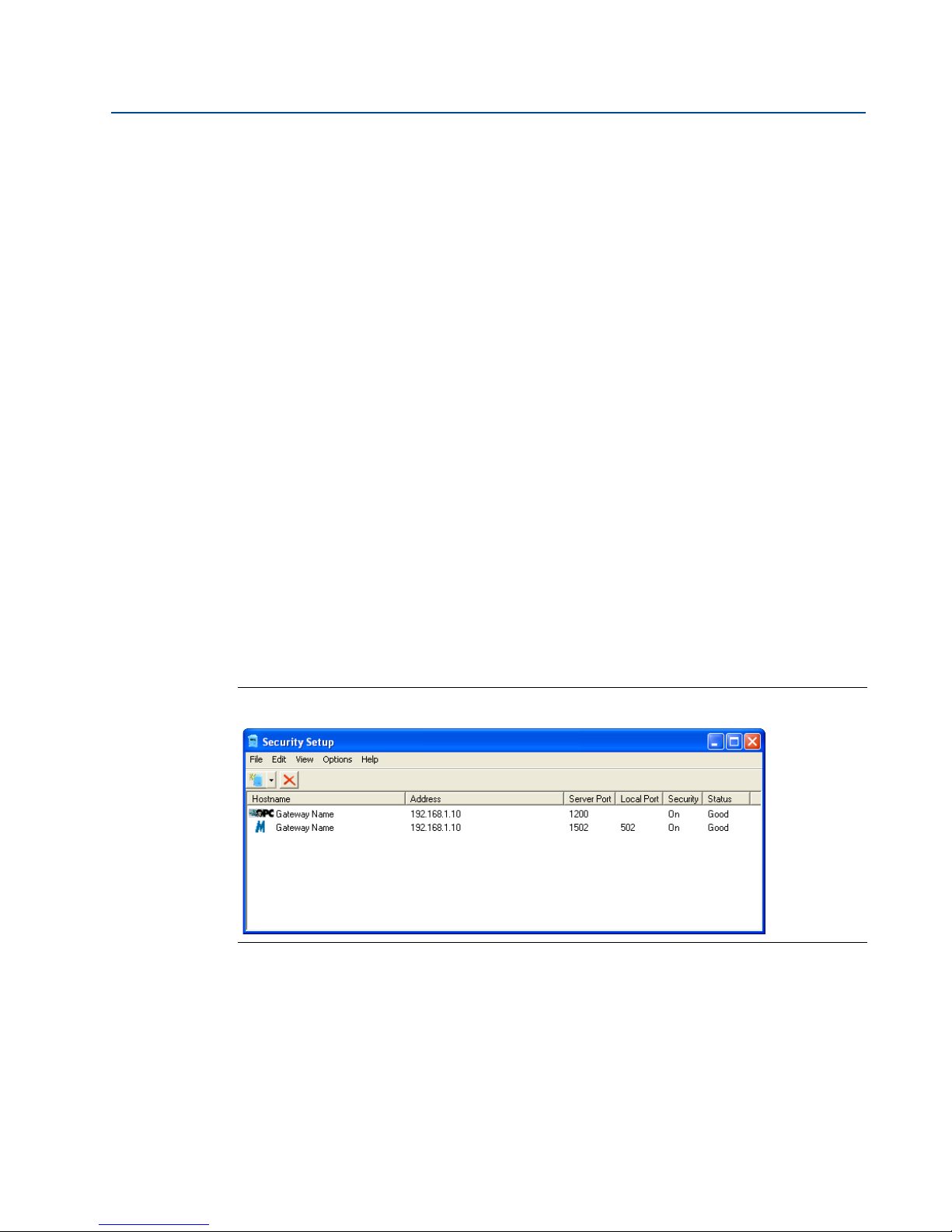
In the Security Setup Utility add a new proxy for each Gateway based on the communication
protocol that is being used. For example, add an OPC proxy for each Gateway that is
communicating OPC.
Use the following procedure to add a new proxy in the Security Setup Utility:
1. Open the Security Setup Utility.
2. Click EDIT>NEW, then select the type of new proxy to be added.
3. Right click on the new proxy entry and select Properties.
4. Enter the target Gateway’s Hostname and IP Address.
5. Click OK.
6. Click FILE>SAVE.
7. When prompted for authentication, enter the admin password for the target Gateway.
Section 4: Software Setup
February 2014
8. Click OK.
9. Repeat steps 2-8 to added additional proxies.
10. Click FILE>EXIT to close the Security Setup Utility.
During this process the Gateway will exchange security certificates (digital signatures) with the
proxy.
Figure 4-2. Security Setup Utility
Software setup
31
Page 40

Section 4: Software Setup
February 2014
4.5 AMS Wireless Configurator
AMS Wireless Configurator helps deploy and configure wireless field devices. It provides an
integrated operating environment that leverages the full capabilities of WirelessHART, including
embedded data trending, charting, and graphical display capabilities provided by enhanced
EDDL technology.
Display and modify device configuration
View device diagnostics
View process variables
Provision a wireless device using the drag-and-drop operation so it can join a Gateway’s
self-organizing network
Enhance AMS Wireless Configurator functionality with the AMS Wireless SNAP-ON
Application
Restrict access to AMS Wireless Configurator functions through the use of security
permissions
See the release notes for information specific to the current release of AMS Wireless
Configurator. To display the release notes, select START>PROGRAMS>AMS WIRELESS CONFIG-
URATOR>HELP.
Reference Manual
00809-0200-4410, Rev BA
4.5.1 Setup
AMS Wireless Configurator supports connectivity to a Wireless Network and a HART Modem.
Both of these interfaces must be configured through the Network Configuration application. To
run this application, select START>PROGRAMS>AMS DEVICE MANAGER>NETWORK
CONFIGURATION.
Note
Do not have the Security Setup Utility running at the same time as the Network Configuration
application or else a configuration error might occur.
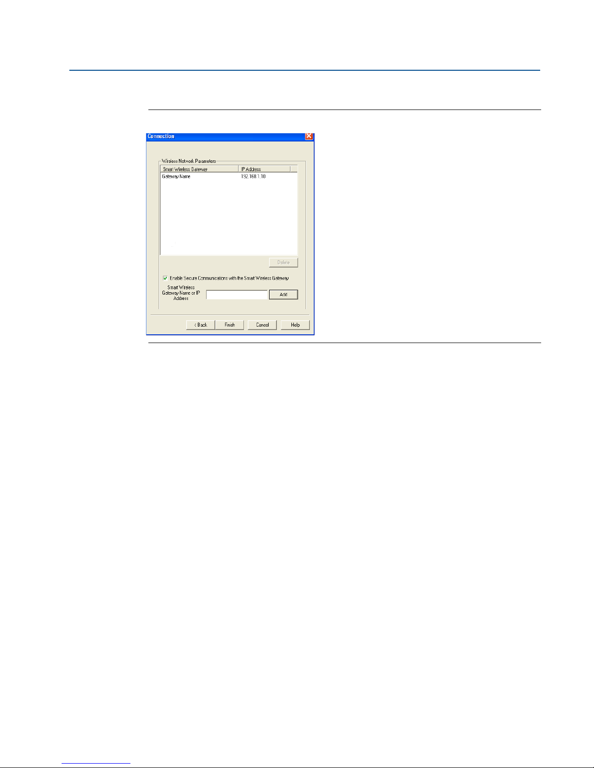
Use the following procedure to configure a wireless network for AMS Wireless Configurator:
1. Open the Network Configuration application.
2. Click Add…
3. Select Wireless Network and click Install…
4. Click Next.
5. Enter a name for the wireless network and click Next.
6. Enter the HostName or IP Address for the Gateway and click Add.
7. Repeat step 6 if multiple Gateways need to be added.
8. Check the box to Enable Secure Communications with the Smart Wireless Gateway.
9. Click Finish to close the configuration window.
10. Click Close to exit the Network Configuration application.
32
Software setup
Page 41
Reference Manual
00809-0200-4410, Rev BA
Figure 4-3. Wireless Network in the Network Configuration
Section 4: Software Setup
February 2014
Use the following procedure to configure a HART modem for AMS Wireless Configurator:
1. Open the Network Configuration application.
2. Click Add… This is shown in Figure 4-3
3. Select HART modem and click Install…
4. Click Next.
5. Enter a name for the HART modem and click Next.
6. Select the HART master type (default is that AMS Wireless Configurator will be the
Primary HART master) and click Next.
7. Select the COM port for the HART modem and click Next.
8. Check the box to Check to support Multi Drop devices.
9. Check the box to Include WirelessHART Adapter.
10. Click Finish to close the configuration window.
11. Click Close to exit the Network Configuration application.
Software setup
33
Page 42

Section 4: Software Setup
February 2014
4.6 Licensing and credits
The latest licensing agreements are included on each disk of the software pack.
This product includes software developed by the OpenSSL Project for use in the OpenSSL
Toolkit. (http://www.openssl.org/)
This product includes software written by Eric Young ([email protected])
Reference Manual
00809-0200-4410, Rev BA
34
Software setup
Page 43
Reference Manual
00809-0200-4410, Rev BA
Section 5 Host integration
Overview . . . . . . . . . . . . . . . . . . . . . . . . . . . . . . . . . . . . . . . . . . . . . . . . . . . . . . . . . . . . . . . . . . page 35
Network architecture . . . . . . . . . . . . . . . . . . . . . . . . . . . . . . . . . . . . . . . . . . . . . . . . . . . . . . . page 35
Internal firewall . . . . . . . . . . . . . . . . . . . . . . . . . . . . . . . . . . . . . . . . . . . . . . . . . . . . . . . . . . . . . page 36
Modbus . . . . . . . . . . . . . . . . . . . . . . . . . . . . . . . . . . . . . . . . . . . . . . . . . . . . . . . . . . . . . . . . . . . page 37
EtherNet/IP™ . . . . . . . . . . . . . . . . . . . . . . . . . . . . . . . . . . . . . . . . . . . . . . . . . . . . . . . . . . . . . . . page 44
5.1 Overview
This section describes how to connect the Gateway to a host system and integrate data
gathered from the field device network. It covers network architectures, security, and data
mapping.
Section 5: Host Integration
February 2014
5.2 Network architecture
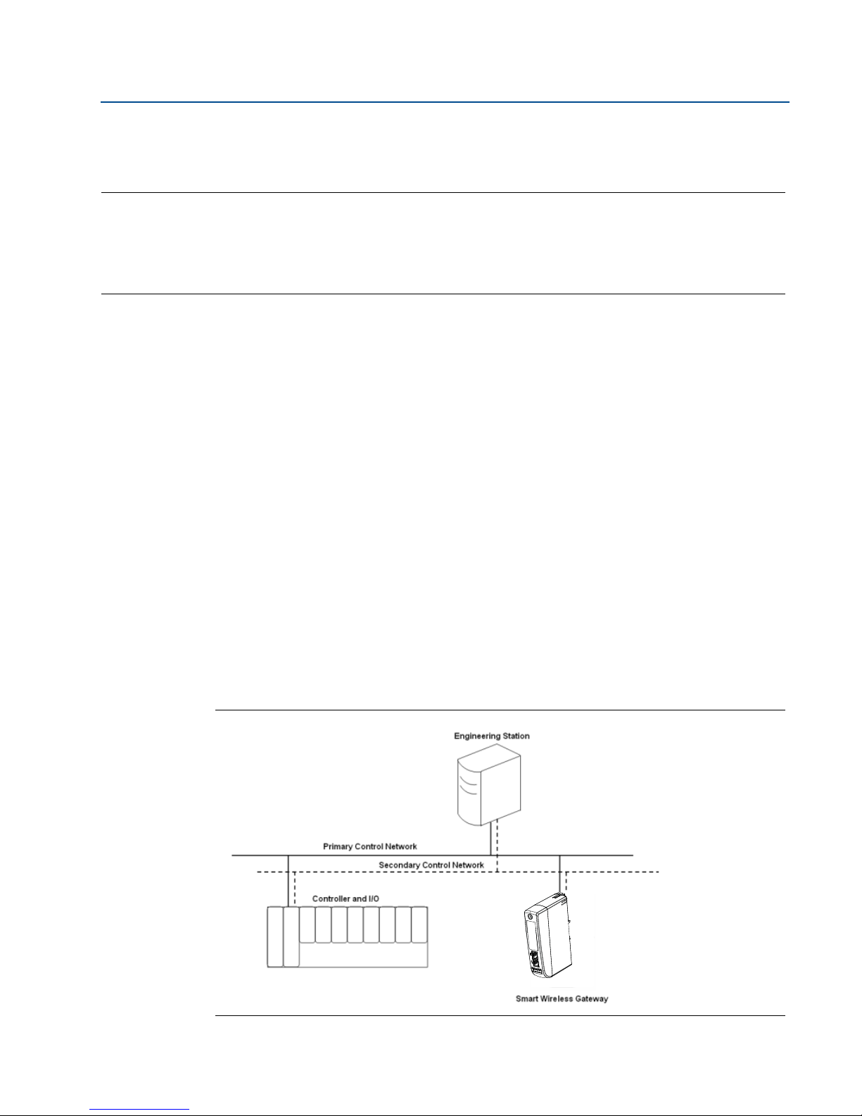
Physical connection types are important when determining the network architecture and what
protocols can be used for integration. Ethernet is the primary physical connection type and
RS485 is available an optional connection type. The following network architecture diagrams
will help when integrating data from the Gateway into the host system.
Ethernet
An Ethernet connection supports Modbus TCP, OPC, AMS Wireless Configurator, EtherNet/IP,
and HART TCP protocols. Using this connection type, the Gateway is wired directly to a control
network (see Figure 5-1) using a network switch, router, or hub. Often there are two networks
for redundancy purposes.
Figure 5-1. Ethernet Architecture
Host Integration
35
Page 44
Section 5: Host Integration
February 2014
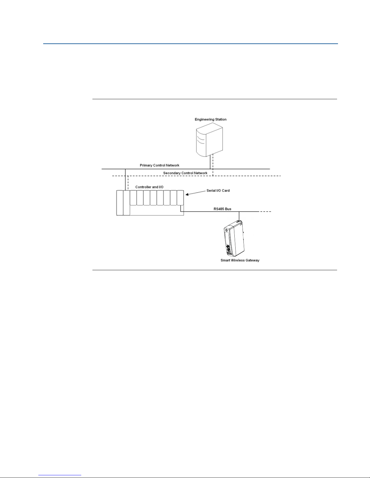
RS485 (serial)
An RS485 connection supports Modbus RTU protocol. Using this connection type, the Gateway
is wired to an RS485 bus which typically leads to a serial I/O card or Modbus I/O card (see
Figure 5-2). Up to 31 Gateways can be connected to a single I/O card in this manner.
Figure 5-2. RS485 Architecture
Reference Manual
00809-0200-4410, Rev BA
5.3 Internal firewall
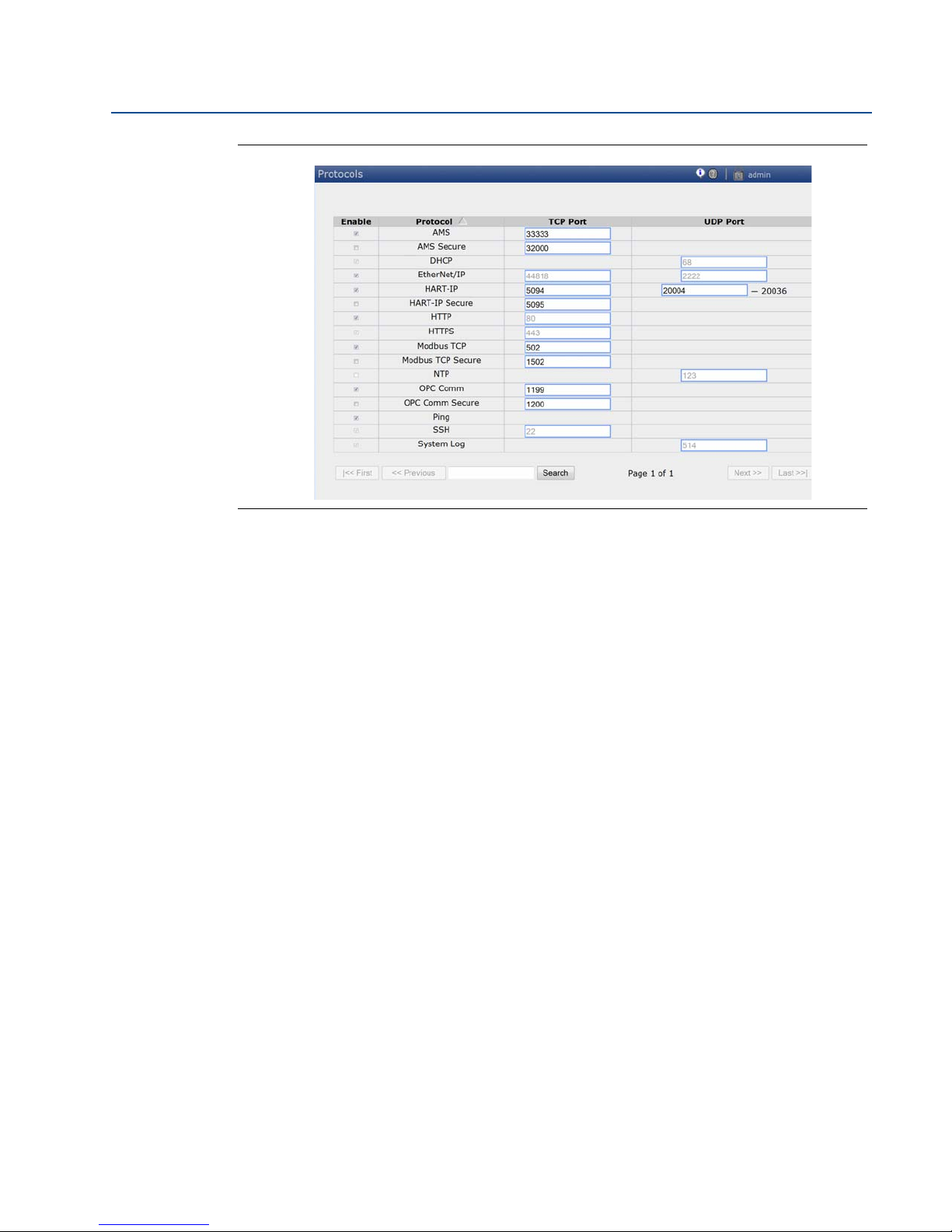
The Gateway supports an internal firewall that inspects both incoming and outgoing data
packets. TCP ports for communication protocols are user configurable, including user specified
port numbers and the ability to disable ports.
The Gateway’s internal firewall settings can be found by navigating to Setup>Security>Proto-
cols.
36
Host Integration
Page 45
Reference Manual
00809-0200-4410, Rev BA
Figure 5-3. Security Protocols page (internal firewall)
Section 5: Host Integration
February 2014
5.4 Modbus
The Gateway supports both Modbus RTU over the RS-485 serial port and Modbus TCP over
Ethernet. It functions as a sub device on the Modbus network and must be polled by a Modbus
master or client (host system).
5.4.1 Communication settings
It is import that the Modbus communication settings in the Gateway match the settings in the
Modbus master or client. Please refer to host system documentation for more information on
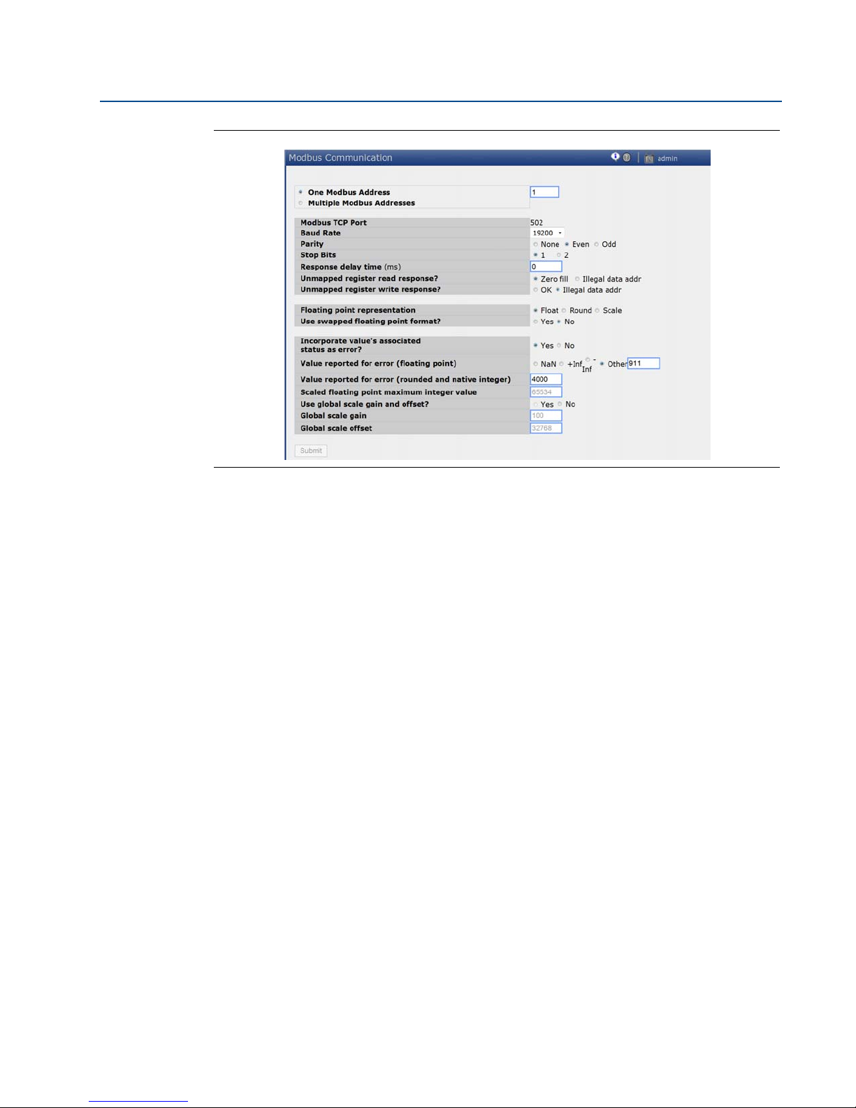
how to configure these settings. The Modbus communication settings can be found by
navigating to Setup>Modbus>Communications.
Host Integration
37
Page 46
Section 5: Host Integration
February 2014
Figure 5-4. Modbus Communications Page
Reference Manual
00809-0200-4410, Rev BA
One Modbus Address: When this option is selected, this address is used by the Gateway for
Modbus RTU communications.
Multiple Modbus Addresses: When this option is selected, a new column for address will
appear on the Modbus mapping page.
Modbus TCP Port: This is the TCP/IP port the Gateway uses for Modbus TCP (Ethernet). To
change TCP/IP port settings, see the Internal Firewall section for more details.
Baud Rate: The data rate or speed of serial communications. This setting is only required for
Modbus RTU.
Parity: This setting determines parity (none, even, or odd) to use for error checking purposes.
This setting is only required for Modbus RTU.
Stop Bits: This setting determines the number (1 or 2) of stop bits to use when ending a
message. This setting is only required for Modbus RTU.
Response delay time (ms): This setting determines how long (ms) the Gateway waits before
responding to a Modbus request. This setting is only required for Modbus RTU.
Unmapped register read response?: This is the value returned by the Gateway if the Modbus
master requests a register with no data assigned to it (empty register). It is recommended this
be set to zero fill to prevent errors.
Floating point representation: This setting determines if the Gateway uses floating point
values or integer values. There are three options for this setting.
Float: This option uses 32 bit floating point values.
Round: This option rounds the data value to the nearest whole number.
Scaled: This option uses scaled integers to offset negative values or increase decimal
point resolution. The equation for scaled integers is:
38
Host Integration
Page 47

Reference Manual
00809-0200-4410, Rev BA
Use swapped floating point format?: This setting switches which register is sent first for a
floating point value. This setting is only used for floating point values.
Incorporate value’s associated status as error?: This setting will cause the Gateway to report
a predetermined value when a communications or critical diagnostic error is received from the
wireless field device. The value is user configurable depending on which floating point
representation is chosen. See Value reported for error below.
Value reported for error (floating point): This setting determines what value is reported if the
wireless field device reports a failure or stops communicating to the Gateway. This setting is
used for floating point values. The choices are NaN (not a number), +Inf (positive infinity), -Inf
(negative infinity), or Other (user specified).
Section 5: Host Integration
February 2014
y = Ax - (B - 32768)
Where:
y = Scaled integer returned by the Gateway
A = Gain for scaled integer value
x = Measured value from wireless field device
B = Offset for scaled integer value
Value reported for error (rounded and native integer): This setting determines what value is
reported if the wireless field device reports a failure or stops communicating to the Gateway.
This setting is used for rounded or scaled integers. The choice is a user specified value between
-32768 and 65535.
Scaled floating point maximum integer value: This determines the maximum integer value
for the purpose scaling integers. 999-65534
Use global scale gain and offset?: This setting determines if a global gain and offset is applied
for scaled integers or if each value has a unique gain and offset. Unique gain and offsets are
found on the Modbus Mapping page.
Global scale gain: This value is multiplied to the data values for the purpose of scaling integers.
If global scaling is not selected, a gain value will be available for each separate data value on the
Modbus Mapping page.
Global scale offset: This value is added to the data values for the purpose of scaling integers. If
global scaling is not selected, an offset value will be available for each separate data value on the
Modbus Mapping page.
5.4.2 Register mapping
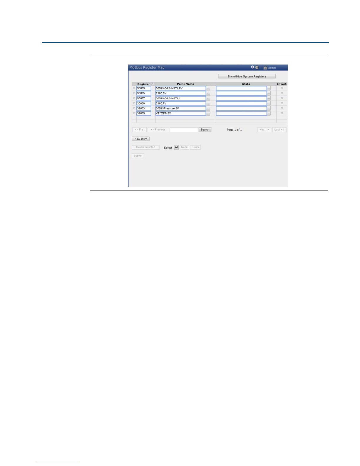
Register Mapping is the process of assigning data points from wireless field devices to Modbus
registers. These registers can then be read by a Modbus master or client. Modbus register
mapping can be found by navigating to Setup>Modbus>Mapping.
Host Integration
39
Page 48
Section 5: Host Integration
February 2014
Figure 5-5. Modbus Register Map Page
Reference Manual
00809-0200-4410, Rev BA
To add a new data point to the Modbus register map:
1. Click New entry.
2. Complete all of the table entries for the new data point (note that the entry columns
may vary based on the Modbus communications settings).
3. Repeat for each new data point.
4. Click Submit.
5. When changes have been accepted, click Return to form.
Address: This is the Modbus RTU address used by the Gateway for this data point. It is possible
to group data points assigning them the same address (i.e. all data points from the same
process unit can have the same address). This column only appears if Multiple Modbus
Addresses is selected on the Modbus Communications page.
Register: This is the Modbus register number used for this data value. Modbus registers hold
two bytes (16 bits) of information; therefore 32 bit floats and integers require two Modbus
registers. Each data point needs a unique Modbus register number, unless they are assigned
different addresses. Register numbers 0-19999 are reserved for Boolean (bit, coil, binary, etc…)
values. Register numbers 20000+ are reserved for floating point or integer values.
Point Name: This is a two part name for the data point. The first part is the HART Tag of the
wireless field device which is producing the data. The second part is the parameter of the
wireless field device.
Point Name is entered as <HART Tag.PARAMETER>. Point Name can be entered using the list of
values (…) or manually entered. The following table gives a list of standard device parameters
which may be considered for Modbus register mapping.
40
Host Integration
Page 49
Reference Manual
00809-0200-4410, Rev BA
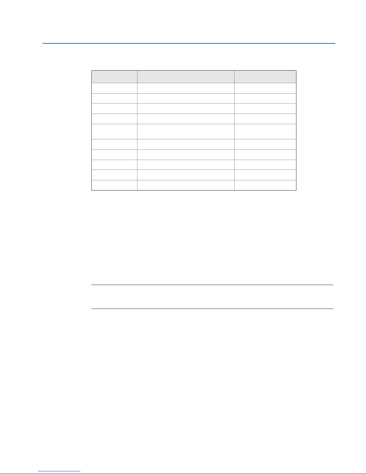
Table 5-1. Device parameters available
Parameter Description Data type
PV Primary Variable 32 bit float
SV Secondary Variable 32 bit float
TV Tertiary Variable 32 bit float
QV Quaternary Variable 32 bit float
RELIABILITY A measure of connectivity to the
Gateway
ONLINE Wireless communications status Boolean
PV_HEALTHY Health status for PV Boolean
SV_HEALTHY Health status for SV Boolean
TV_HEALTHY Health status for TV Boolean
QV_HEALTHY Health status for QV Boolean
32 bit float
Section 5: Host Integration
February 2014
PV, SV, TV, and QV (dynamic variables) will vary by device type. Please refer to the device’s
documentation for more information on what value is represented by each dynamic variable.
RELIABILITY and ONLINE relate to wireless communications. RELIABILITY is the percentage of
messages received from the wireless field device. ONLINE is a true/false indication of whether
the device is communicating on the wireless network.
**_HEALTHY parameters are a true/false indication of the health of a particular variable (** =
dynamic variable – PV, SV, etc…). These parameters incorporate critical diagnostics from the
wireless field device as well as communication status.
Note
The **_HEALTHY parameters are a great indication of the health and communications status of
the data values.
State (state value): The value of a data point which drives a Modbus output of 1. For example, if
a data point is reported as either True or False, a state value of True will report a 1 for True and 0
for False. A state of False will report a 0 for True and a 1 for False. State is only required for
register numbers 0-19999 (Boolean, bit, coil, binary, etc…).
Invert: This check box will invert the Modbus output from a 1 to a 0 or a 0 to a 1. Invert is only
used for Boolean values using register numbers 0-19999.
Gain: This value is multiplied to the data value for the purpose of scaling integers. Gain is only
required if scaled is chosen on the Modbus communications page and globe gain and offset is
not chosen.
Offset: This value is added to the data value for the purpose of scaling integers. Offset is only
required if scaled is chosen on the Modbus communications page and globe gain and offset is
not chosen.
Host Integration
41
Page 50

Section 5: Host Integration
February 2014
Predefined Modbus registers
In addition to user configurable parameters, the Gateway also supports a list of predefined
Modbus registers with diagnostics and test parameters. The following table is a list of the
predefined Modbus registers.
Reference Manual
00809-0200-4410, Rev BA
42
Host Integration
Page 51

Reference Manual
00809-0200-4410, Rev BA
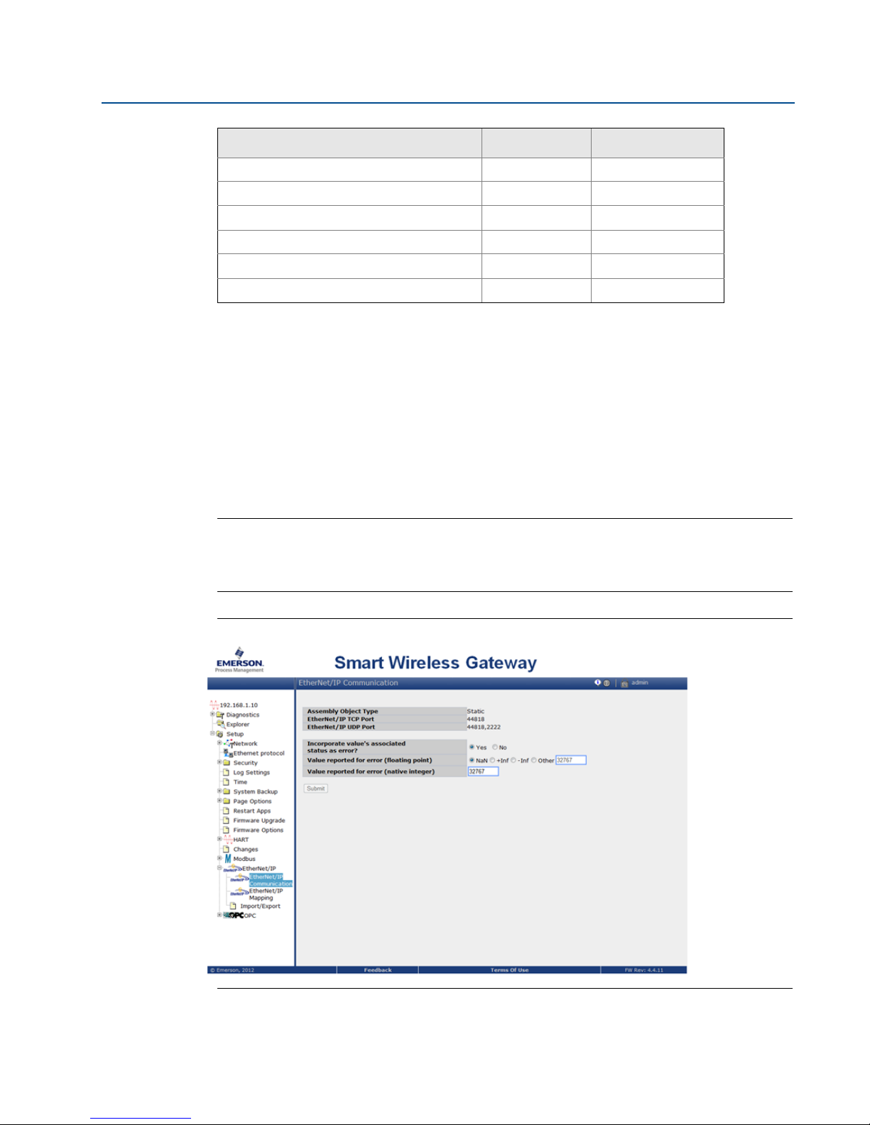
Table 5-2. Predefined Modbus Registers
Section 5: Host Integration
February 2014
Description Register Data type
Current Year (1) 49001 32 bit int
Current Month (1) 49002 32 bit int
Current Day (1) 49003 32 bit int
Current Hour (1) 49004 32 bit int
Current Minute (1) 49005 32 bit int
Current Second (1) 49006 32 bit int
Messages Received 49007 32 bit int
Corrupt Messages Received 49008 32 bit int
Messages Sent With Exception 49009 32 bit int
Messages Sent Count 49010 32 bit int
Valid Messages Ignored 49011 32 bit int
Constant Float 12345.0 49012 32 float
SYSTEM_DIAG.HART_DEVICES 49014 32 bit int
SYSTEM_DIAG.ADDITIONAL_STATUS_0 49015 8 bit unsigned int
SYSTEM_DIAG.ADDITIONAL_STATUS_1 49016 8 bit unsigned int
SYSTEM_DIAG.ADDITIONAL_STATUS_2 49017 8 bit unsigned int
SYSTEM_DIAG.ADDITIONAL_STATUS_3 49018 8 bit unsigned int
SYSTEM_DIAG.ADDITIONAL_STATUS_4 49019 8 bit unsigned int
SYSTEM_DIAG.ADDITIONAL_STATUS_5 49020 8 bit unsigned int
SYSTEM_DIAG.ADDITIONAL_STATUS_6 49021 8 bit unsigned int
SYSTEM_DIAG.ADDITIONAL_STATUS_7 49022 8 bit unsigned int
SYSTEM_DIAG.ADDITIONAL_STATUS_8 49023 8 bit unsigned int
SYSTEM_DIAG.ADDITIONAL_STATUS_9 49024 8 bit unsigned int
SYSTEM_DIAG.ADDITIONAL_STATUS_10 49025 8 bit unsigned int
SYSTEM_DIAG.ADDITIONAL_STATUS_11 49026 8 bit unsigned int
SYSTEM_DIAG.ADDITIONAL_STATUS_12 49027 8 bit unsigned int
SYSTEM_DIAG.UNREACHABLE 49028 32 bit int
SYSTEM_DIAG.UPTIME 49029 32 bit int
SYSTEM_DIAG.TEST_BOOLEAN 49031 Boolean
SYSTEM_DIAG.TEST_BYTE 49032 8 bit int
Host Integration
43
Page 52
Section 5: Host Integration
February 2014
Description Register Data type
SYSTEM_DIAG.TEST_UNSIGNED_BYTE 49033 8 bit unsigned int
SYSTEM_DIAG.TEST_SHORT 49034 16 bit int
SYSTEM_DIAG.TEST_UNSIGNED_SHORT 49035 16 bit unsigned int
SYSTEM_DIAG.TEST_INT 49036 32 bit int
SYSTEM_DIAG.TEST_UNSIGNED_INT 49038 32 bit unsigned int
SYSTEM_DIAG.TEST_FLOAT 49040 32 bit float
Reference Manual
00809-0200-4410, Rev BA
5.5 EtherNet/IP
Communication settings
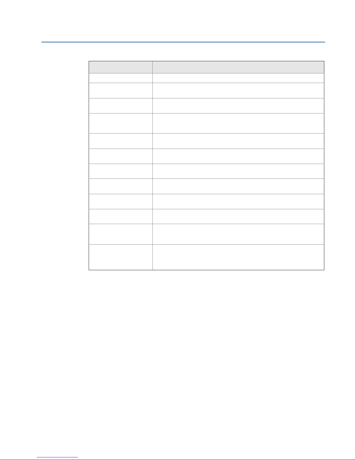
It is important that the EtherNet/IP communication settings in the Gateway match the setting in
the EtherNet/IP master or client. Refer to the host system documentation for more information
on how to configure these settings, or to the reference manual for the EtherNet/IP: technical
document 00809-0500-4420. The EtherNet/IP communication settings can be found by
navigating to Setup>EtherNet/IP>Communications.
Note
EtherNet/IP can be integrated with any approved EtherNet/IP ODVA member. Other protocols
such as HARTIP are still functional within the Gateway. Please consult the Product Data Sheet
(Doc. number 00813-0200-4420) for ordering options.
Figure 5-6. EtherNet/IP Communications Page
™
44
Host Integration
Page 53
Reference Manual
00809-0200-4410, Rev BA
Table 5-3. Setup>EtherNet/IP>EtherNet/IP Communication
Section 5: Host Integration
February 2014
Ter ms Description
Assembly Object Type EtherNet/IP use Static assembly object.
EtherNet/IP TCP Port The TCP Port used to access EtherNet/IP TCP data directly from the
Gateway.
EtherNet/IP UDP Ports The UDP Ports used to access EtherNet/IP UDP data directly from the
Incorporate value’s
associated status as
error?
Value reported for error
(floating point)
NaN Not a number is reported if the value’s associated status indicates a critical
+Inf Positive infinity is reported if the value’s associated status indicates a
-Inf Negative infinity is reported if the value’s associated status indicates a
Other User defined value is reported if the value’s associated status indicates a
Value reported for error
(native integer)
Unmapped parameter
read response
Parameter mapping Register Mapping is the process of assigning data points from wireless field
Gateway.
If the HART variable status indicates a critical failure or if there is a loss of
communications, it will be reported through the EtherNet/IP member.
Chooses what value is reported if the value’s associated status indicates a
critical failure. Only used if the Gateway is using float representation
failure.
critical failure.
critical failure.
critical failure.
User defined value is reported if the value’s associated status indicates a
critical failure. Only used if the Gateway is using integer representation.
This is the value returned by the Gateway if the EtherNet/IP master
requests a register with no data assigned to it (empty register). It is
recommended this be set to zero fill to prevent errors.
devices to EtherNet/IP registers. These registers can then be read by a
EtherNet/IP master or client. EtherNet/IP register mapping can be found
by navigating to Setup>EtherNet/IP>Mapping.
Host Integration
45
Page 54
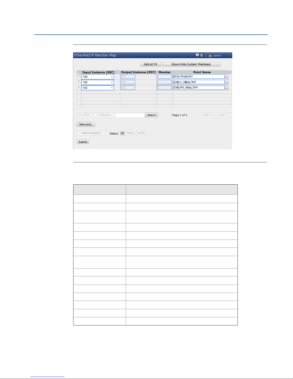
Section 5: Host Integration
February 2014
Figure 5-7. EtherNet/IP Register Map Page
Reference Manual
00809-0200-4410, Rev BA
Table 5-4. Summary of terms used for the EtherNet/IP mapping page
Ter ms Description
Input Instance EtherNet/IP Input Static Assembly Instance - 496 bytes.
Output Instance EtherNet/IP Output Static Assembly Instance - 496 bytes.
Member EtherNet/IP Instance Member in which data will get
Point Name Assigned data point in the format HARTtag.parameter.
New entry Creates a new entry in this table.
<<First Navigates to the first page of this table.
<<Previous Navigates to the previous page of this table.
Search Finds the next occurrence of the characters entered into
Next>> Navigates to the next page of this table.
Last>> Navigates to the last page of this table.
Delete Selected Removes the selected entry from this table.
Select All Selects all table entries.
Select None Deselects all table entries.
Select Errors Selects all table entries that have an error message.
Submit Accepts all changes (highlighted in yellow).
produced or consumed.
this field.
46
Host Integration
Page 55

Reference Manual
00809-0200-4410, Rev BA
To add a new data point to the EtherNet/IP register map:
1. Click New entry.
2. Complete all of the table entries for the new data point (note that the entry columns
3. Repeat for each new data point.
4. Click Submit.
5. When changes have been accepted, click Return to form.
See Table 5-1 on page 5-41 for options of parameters that can be mapped.
Section 5: Host Integration
February 2014
may vary based on the EtherNet/IP communications settings).
Host Integration
47
Page 56

Page 57
Reference Manual
00809-0200-4410, Rev BA
Section 6 Troubleshooting
This section provides basic troubleshooting tips for the Smart Wireless Field Network. To receive
technical support by phone:
Global Service Center
Software and Integration support
United States – 1 800 833 8314
International – 63 2 702 1111
Customer Central
Technical support, quoting, and order-related questions
United States – 1 800 999 9307 (7:00 am to 7:00 pm CST)
Asia Pacific – 65 6777 8211
Europe / Middle East / Africa – 49 (8153) 9390
Section 6: Troubleshooting
February 2014
Or email the wireless specialists at:
Initial connection
Web browser returns page not
found
Can not find Gateway after
changing IP address
Can not find Gateway using
Secondary Ethernet Port
Can not log into the Gateway 1. Verify the user name and password. The administrator user name is admin and the
1. Connect the Gateway and PC/Laptop
2. Verify the Gateway is properly powered, 24 VDC (nominal) and 250 mA.
3. Verify which Ethernet port is being used on the Gateway.
4. Verify the IP address for the Gateway (default primary port is 192.168.1.10, default
secondary port is 192.168.2.10 or for DeltaV Ready Gateway’s default primary port
is 10.5.255.254, default secondary port is 10.9.255.254).
5. Verify the IP address of the PC/Laptop is in the same subnet range as the Gateway
(i.e. If the Gateway IP is 155.177.0.xxx, then the PC/Lap IP address should be
155.177.0.yyy).
6. Disable internet browser proxy settings.
1. Verify the IP address of the PC/Laptop is in the same subnet range as the Gateway
(i.e. If the Gateway IP is 155.177.0.xxx, then the PC/Lap IP address should be
155.177.0.yyy). Consider resetting the gateway to factory defaults.
1. Verify which Ethernet port is being used on the Gateway.
2. Verify the IP address for the Gateway (default primary port is 192.168.1.10, default
secondary port is 192.168.2.10).
3. Verify the IP address of the PC/Laptop is in the same subnet range as the Gateway
(i.e. If the Gateway IP is 155.177.0.xxx, then the PC/Lap IP address should be
155.177.0.yyy). Verify this option was ordered with the Gateway.
default password is default. See
the Gateway.
Ta bl e 2 - 1. If unable to connect, consider resetting
Tro u bl esh o oti ng
49
Page 58
Section 6: Troubleshooting
February 2014
AMS Wireless Configurator
Reference Manual
00809-0200-4410, Rev BA
Gateway does not appear in AMS
Wireless Configurator
Wireless devices do not appear
under the Gateway
Wireless device appears with red
HART symbol
Device configuration items are
grayed out
Wireless field devices
Wireless device does not appear
on the network
1. Verify the Security Setup Utility is installed on the same PC as AMS Wireless
Configurator.
2. Setup a wireless network interface using the Network Configuration application. See
Section 4: Software setup.
3. Verify if the wireless network interface is configured for Secure Gateway
Communications.
4. Verify secure/unsecure AMS Wireless Configurator protocol settings in the Gateway.
Log on to the Gateway and navigate to SETUP > SECURITY > PROTOCOLS.
5. Restart AMS Wireless Configurator data server. Right click on AMS Wireless
Configurator server icon in the Windows system tray (lower right corner) and select
stop server.
1. Verify wireless devices are connected to the Gateway. Log on to the Gateway and
navigate to EXPLORER.
2. Right click on wireless network and select rebuild hierarchy.
1. Install latest device support files from AMS Wireless Configurator. Go to
www.emersonprocess.com > BRANDS > AMS SUITE > AMS DEVICE MANAGER >
DEVICE DESCRIPTION (DDs).
1. Verify whether current or historical information is being displayed. This setting is
displayed at the bottom of each device configuration screen. Configuration requires
the Current setting.
2. For security purposes a configuration timeout is applied to sessions that have been
idle for more than 30 minutes. Log back into AMS Wireless Configurator.
1. Verify the device has power.
2. Verify the device is within effect communications range.
3. Verify the proper Network ID has been entered into the device.
Wireless device appears in the join
failure list
Wireless device appears with
service denied
1. Re-enter the Network ID and Join Key into the device.
1. Verify the total number of devices on the network (25 max).
2. Go to SETUP > NETWORK > BANDWIDTH and click analyze bandwidth
(Note: any changes will require the network to reform)
3. Reduce the update rate for the device.
50
Tro u bl esh o oti ng
Page 59
Reference Manual
00809-0200-4410, Rev BA
Modbus communications
Section 6: Troubleshooting
February 2014
Can not communicate using
Modbus RTU
Can not communicate using
Modbus TCP
Can not communicate using
secure Modbus TCP
OPC communications
OPC application can not find a
Gateway OPC server
Gateway OPC server does not
show any Gateways
1. Verify the use of RS-485
2. Verify wiring connections. See Section 3: Mounting and connection.
3. Verify if termination or a pull up is required. See Figure 3-7.
4. Ver ify t hat Modbus s erial commu nications setting i n the Gateway matc h the M odbus
Host settings. Log on to the Gateway and navigate to SETUP > MODBUS >
COMMUNICATIONS.
5. Verify the Modbus address for the Gateway.
6. Verify Modbus register mapping in the Gateway. Log on to the Gateway and navigate
to SETUP > MODBUS > MAPPING.
1. Verify secure / unsecure Modbus protocol settings in the Gateway. Log on to the
Gateway and navigate to SETUP > SECURITY > PROTOCOLS.
2. Verify the Modbus TCP communications settings in the Gateway. Log on to the
Gateway and navigate to SETUP > MODBUS > COMMUNICATIONS.
3. Verify Modbus register mapping in the Gateway. Log on to the Gateway and navigate
to SETUP > MODBUS > MAPPING.
1. Verify the Security Setup Utility has been installed.
2. Configure a Secure Modbus Proxy for the Gateway. See Section 4: Software setup.
3. Verify secure / unsecure Modbus protocol settings in the Gateway. Log on to the
Gateway and navigate to SETUP > SECURITY > PROTOCOLS.
4. Verify the Modbus TCP communications settings in the Gateway. Log on to the
Gateway and navigate to SETUP > MODBUS > COMMUNICATIONS.
5. Verify Modbus register mapping in the Gateway. Log on to the Gateway and navigate
to SETUP > MODBUS > MAPPING.
1. Verify the Security Setup Utility has been installed on the same PC as the OPC
application.
2. Configure an OPC proxy for the Gateway. See Section 4: Software setup.
1. Configure an OPC proxy for the Gateway. See Section 4: Software setup.
Gateway OPC server does not
show any data tags
EtherNet/IP
The Gateway is not publishing the
parameters
Tro u bl esh o oti ng
1. Configure the Gateway OPC Browse Tree. Log on to the Gateway and navigate to
SETUP > OPC > OPC BROWSE TREE.
2. Verify the connection status for the OPC proxy in the Security Setup Utility.
3. Verify if the OPC proxy is configured for secure or unsecure communications.
4. Verify secure / unsecure OPC protocol settings in the Gateway. Log on to the
Gateway and navigate to SETUP > SECURITY > PROTOCOLS.
5. Verify network firewall and port settings.
Verify connection is established with EtherNet/IP. Navigate to SETUP > SECURITY >
PROTOCOLS
Reference technical document 00809-0500-4420: Installation manual to connect to an
Allen Bradley system.
51
Page 60

Page 61

Reference Manual
00809-0200-4410, Rev BA
Section 7 Glossary
This glossary defines terms used throughout this manual or that appear in the web interface of
the Smart Wireless Gateway.
Ter m Definition
Section 7: Glossary
February 2014
Access
Control List
Active
Advertising
Baud Rate Communication speed for Modbus RTU.
Burst Rate The interval in which a wireless field device transmits measurement and status data to
Certificate A digital signature used to authenticate a client/server while using encrypted
Connectivity Typically refers to a combination of communication statistics and link reliability of a
Device ID A hexidecimal number that provides unique device identification.
DHCP Dynamic Host Configuration Protocol: Used to automatically configure the TCP/IP
Domain A unique designator on the internet comprised of symbols separated by dots such as:
Gateway Refers to the Smart Wireless Gateway.
HART Tag The device’s electronic tag that the Gateway uses for all host integration mapping. Refers
Host Name A unique designator in a domain associated with the IP address of a device such as:
HTML Hyper Text Markup Language: The file format used to define pages viewed with a web
A list of all devices that are approved to join the network. Each device will also have a
unique join key. Also referred to as a white list.
An operational state of the network manager that causes the entire wireless field
network to send messages looking for new or unreachable devices to join the network.
the Gateway. Same as Update Rate.
communications.
wireless field device. May also refer to the connection between the Gateway and the Host
System.
parameters of a device.
this.domain.com
to the HART long tag (32 characters, used for HART 6 or 7 devices) or the HART message
(32 characters, only used for HART 5 wired devices connected via a WirelessHART
adapter)
device.this.domain.com. In that example the hostname is device.
browser.
HTTP Hyper Text Transfer Protocol: The protocol that defines how a web server sends and
HTTPS HTTP over an encrypted Secure Sockets Layer (SSL)
Join Failure When a wireless field device fails to join the WirelessHART network. Most join failures are
Join Key Hexadecimal security code that allows wireless field devices to join the wireless field
Latency The time from when a message leaves a wireless field device until it reaches the Gateway.
Netmask A string of 1's and 0's that mask out or hide the network portion of an IP address leaving
Network I.D. Numeric code that associates wireless field devices to the Gateway. This code must be
Glossary
receives data to and from a web browser.
due to security reasons (missing or incorrect join key, not on access control list, etc.)
network. This code must be identical in the device and the Gateway.
only the host component.
identical in the device and the gateway.
53
Page 62

Section 7: Glossary
February 2014
Reference Manual
00809-0200-4410, Rev BA
Ter m Definition
Network
Manager
Operational function within the Smart Wireless Gateway that automatically handles all
device connections and scheduling of wireless data.
NTP Network Time Protocol. Used to keep the system time synchronized with a network time
server.
Path A wireless connection between two devices in a wireless network. Also referred to as a
hop.
Path Stability A measure of connectivity between two devices in the wireless network. Calculated as
the ratio of the number of received messages over the number of expected messages.
Primary
Ethernet 1 or Fiber Optic port that is used for primary host communications.
Interface
Private
Network/LAN
A local connection between a Smart Wireless Gateway and a PC/Laptop. This network is
used for commissioning and configuration of the Gateway.
Reliability A measure of connectivity between the Gateway and a wireless field device. Calculated as
the ratio of the number of received messages over the number of expected messages.
Takes into account all paths.
RSSI Received signal strength indication (dBm) for the wireless field device.
Secondary
Ethernet 2 port that is used for backup connection or a maintenance port for local access.
Interface
Security
Setup Utility
Self-Organizi
ng Network
Service
A software application that enables secure communications between the Gateway and
host system, asset management software, data historians, or other applications.
Mesh network technology in which a network manager automatically handles all device
connections and scheduling of wireless data.
The device has been denied bandwidth and can not publish its regular updates.
Denied
TCP /IP Transmission Control Protocol / Internet Protocol. The protocol that specifies how data is
transmitted over Ethernet.
Update Rate The interval in which a wireless field device transmits measurement and status data to
the Gateway. Same as Burst Rate.
54
Wireless Field
Device(s)
Wireless Field
Network
Wireless
Plant
Network
WirelessHART field devices that are a part of the wireless field network.
WirelessHART network, consisting of Smart Wireless Gateway and multiple wireless field
devices.
Industrial WiFi network, used to integrate the Wireless Field Network into the control
network.
Glossary
Page 63
Reference Manual
00809-0200-4410, Rev BA
Appendix A: Product Specifications
February 2014
Appendix A Product specifications
Ordering information . . . . . . . . . . . . . . . . . . . . . . . . . . . . . . . . . . . . . . . . . . . . . . . . . . . . . . . . page 55
Functional specifications . . . . . . . . . . . . . . . . . . . . . . . . . . . . . . . . . . . . . . . . . . . . . . . . . . . . . page 57
Physical specifications . . . . . . . . . . . . . . . . . . . . . . . . . . . . . . . . . . . . . . . . . . . . . . . . . . . . . . . page 58
Communication specifications . . . . . . . . . . . . . . . . . . . . . . . . . . . . . . . . . . . . . . . . . . . . . . . . page 58
Self-organizing network specifications . . . . . . . . . . . . . . . . . . . . . . . . . . . . . . . . . . . . . . . . . page 59
System security specifications . . . . . . . . . . . . . . . . . . . . . . . . . . . . . . . . . . . . . . . . . . . . . . . . page 59
Dimensional drawings . . . . . . . . . . . . . . . . . . . . . . . . . . . . . . . . . . . . . . . . . . . . . . . . . . . . . . . page 61
Accessories and spare parts . . . . . . . . . . . . . . . . . . . . . . . . . . . . . . . . . . . . . . . . . . . . . . . . . . page 63
A.1 Ordering information
Table A-1. Smart Wireless Gateway Ordering Information
★ The Standard offering represents the most common options. The starred options (★) should be selected for best delivery.
__The Expanded offering is subject to additional delivery lead time.
Model Product description
1410
Wireless configuration
Standard Standard
A
Ethernet communications - physical connection
Standard Standard
(1)(2)
1
(3)(4)
2
Serial communication
Standard Standard
N
(5)
A
Smart Wireless Gateway, 2.4 GHz DSSS, WirelessHART, Webserver, AMS Ready, HART IP
25 Device Network (10.5-30 VDC)
Single Ethernet Connection
Dual Ethernet Connection
None
Modbus RTU via RS-485
★
★
★
★
★
Product specifications
55
Page 64
Appendix A: Product Specifications
February 2014
Reference Manual
00809-0200-4410, Rev BA
Table A-1. Smart Wireless Gateway Ordering Information
★ The Standard offering represents the most common options. The starred options (★) should be selected for best delivery.
__The Expanded offering is subject to additional delivery lead time.
Ethernet communication - data protocols
(6)
Standard Standard
D1
D2
D3
D4
D5
D6
E2
E3
(6)
(6)
(6)
(7)
Modbus TCP/IP
OPC
EtherNet/IP
Modbus TCP/IP, OPC
EtherNet/IP, Modbus TCP/IP
EtherNet/IP, OPC
Ovation Ready
Webserver Only
Antenna options
(8)
★
★
★
★
★
★
★
★
Standard Standard
WX2
WL2
WN2
Basic Antenna
SMA-to-N-Type Adapter Cable, and Remote Antenna Kit
(9)
SMA-to-N-Type Adapter Cable, and High-Gain Remote Antenna Kit
★
★
★
Product certifications
Standard Standard
NA
N5
N6
No Approvals
FM Division 2, Non-incendive
CSA Division 2 (Suitable for Canada and the United States)
★
★
★
Options (Include with selected model number)
Host integration
Standard Standard
H6
H9
Allen Bradley
Other
Oil and gas options
Standard Standard
G
Oil and Gas Monitor Page
Typical model number: 1410 A 2 D5 WX2 NA
(1) Single active 10/100 baseT Ethernet port with RJ45 connector.
(2) Additional ports disabled.
(3) Dual active 10/100 baseT Ethernet ports with RJ45 connectors.
(4) Multiple active ports have separate IP addresses, firewall isolation, and no packet forwarding.
(5) Convertible to RS232 via adapter, not included with Gateway.
(6) Selection of Dual Ethernet option code 2 is recommended.
(7) Requires (A) Modbus RTU via RS-485 Communication protocol.
(8) The WL2 and WN2 options require minor assembly.
(9) Not available in all countries.
(10) Support documentation included in the package.
(10)
★
★
★
56
Product specifications
Page 65

Reference Manual
12 24
30
125
250
Voltag e (VD C)
Current (mA)
Operating
Region
00809-0200-4410, Rev BA
A.2 Functional specifications
Input voltage
10.5-30 VDC Class 2 Power Supply
Current draw
Operating current draw is based on 3.0 Watt power consumption.
Appendix A: Product Specifications
February 2014
Radio frequency power output from antenna
Maximum of 10 mW (10 dBm) EIRP for WL or WX antenna types
Maximum of 40 mW (16 dBm) EIRP for WN2 high gain option
Environmental
Operating Temperature Range:
-40 to 167 °F (-40 to 75 °C)
Operating Humidity Range:
0-100% relative humidity
EMC performance
Complies with EN61326-1:2006.
Antenna options
Optional remote mount omnidirectional antenna
Antenna
2 dBi rubber dipole with SMA connector
SMA connection is female
Product specifications
57
Page 66

Appendix A: Product Specifications
February 2014
A.3 Physical specifications
Weight
0.70 lb. (0,318 kg)
Material of construction
Housing
Polymer
Rail mount
Top hat rail EN 50022 35 mm X 7.5 mm and 35 mm x 15 mm
A.4 Communication specifications
Reference Manual
00809-0200-4410, Rev BA
Isolated RS485
2-wire communication link for Modbus RTU multidrop connections
Baud rate: 57600, 38400, 19200, or 9600
Protocol: Modbus RTU
Wiring: Single twisted shielded pair, 18 AWG. Wiring distance is approximately 4000 ft. (1,524
m)
Ethernet
10/100base-TX Ethernet communication port
Proto co ls: Modbus TCP, OPC, Eth er Ne t/ IP, H ART-IP, ht tp s ( fo r Web Int er fa ce )
Wiring: Cat5e shielded cable. Wiring distance 328 ft. (100 m).
Modbus
Supports Modbus RTU and Modbus TCP with 32-bit floating point values, integers, and scaled
integers.
Modbus Registers are user-specified.
OPC
OPC server supports OPC DA v2, v3
EtherNet/IP
Supports EtherNet/IP protocol with 32 bit Floating Point values and Integers. EtherNet/IP
Assembly Input-Output instances are user configurable. EtherNet/IP specifications are managed
58
Product specifications
Page 67

Reference Manual
00809-0200-4410, Rev BA
and distributed by ODVA. For details on capabilities please see the Smart Wireless Gateway to
Allen Bradley Integration Manual (Document No. 00809-0500-4420) on rosemount.com.
Appendix A: Product Specifications
A.5 Self-organizing network specifications
Protocol
IEC 62591(WirelessHART), 2.4 - 2.5 GHz DSSS.
Maximum network size
25 wireless devices @ 2 seconds or greater
12 wireless devices @ 1 seconds
Supported device update rates
1, 2, 4, 8, 16, 32 seconds or 1 - 60 minutes or greater depending on the device
February 2014
Network size/latency
25 Devices/ less than 5 sec.
Data reliability
Greater than 99%
A.6 System security specifications
Ethernet
Secure Sockets Layer (SSL) enabled (default) TCP/IP communications
Smart Wireless Gateway access
Role-based Access Control (RBAC) including Administrator, Maintenance, Operator, and
Executive. Administrator has complete control of the Gateway and connections to host systems
and the self-organizing network.
Self-organizing network
AES-128 Encrypted WirelessHART, including individual session keys. Drag and Drop device
provisioning, including unique join keys and white listing.
Internal firewall
User Configurable TCP ports for communications protocols, including Enable/Disable and user
specified port numbers. Inspects both incoming and outgoing packets.
Product specifications
59
Page 68

Appendix A: Product Specifications
February 2014
Third party certification
Wurldtech: Achilles Level 1 certified for network resiliency
National Institute of Standards and Technology (NIST): Advanced Encryption Standard (AES)
Algorithm conforming to Federal Information Processing Standard Publication 197 (FIPS-197).
Reference Manual
00809-0200-4410, Rev BA
60
Product specifications
Page 69
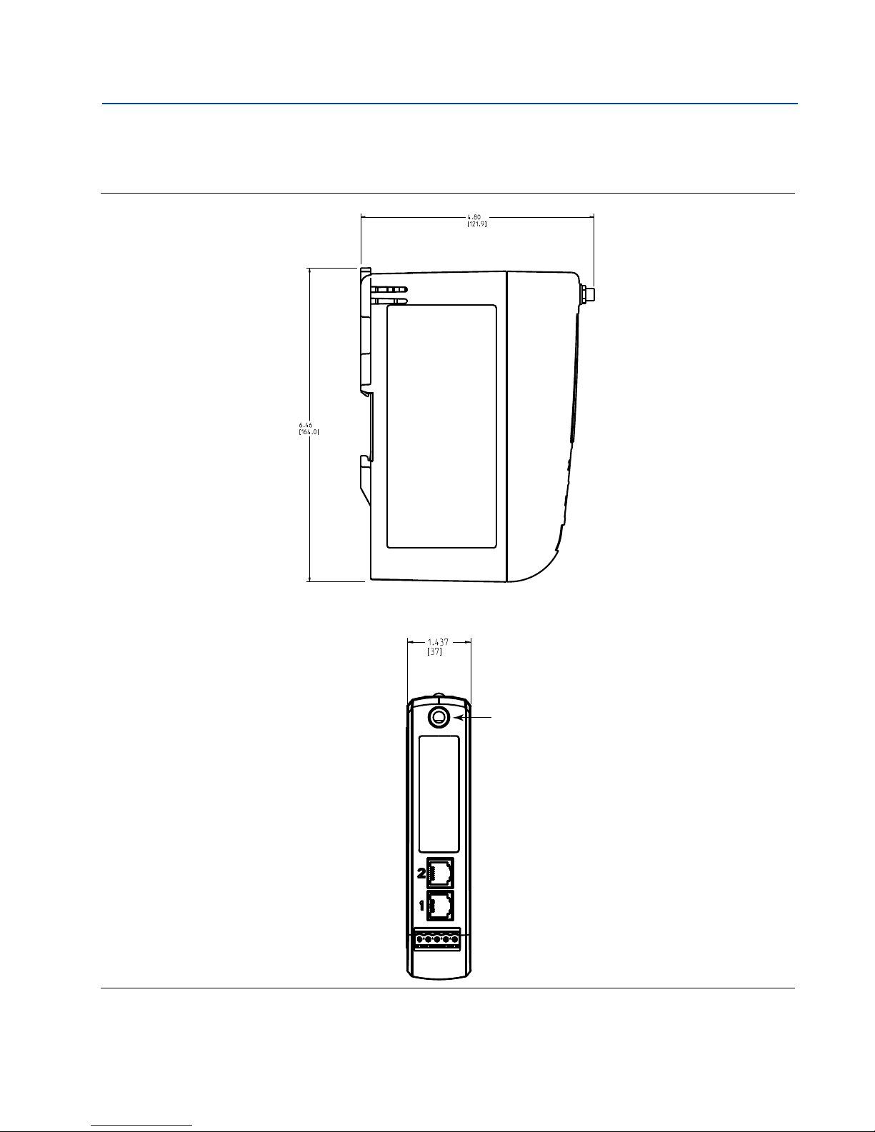
Reference Manual
RF connector on 1410
is an SMA female.
Matching RF cable to
antenna should be a
SMA male.
NOTE: Allow extra
space in front of unit
for wiring, antenna
connector and
antenna cable service
loop.
00809-0200-4410, Rev BA
A.7 Dimensional drawings
Figure A-1. Smart Wireless Gateway
Appendix A: Product Specifications
February 2014
Dimensions are in inches (millimeters).
Product specifications
61
Page 70
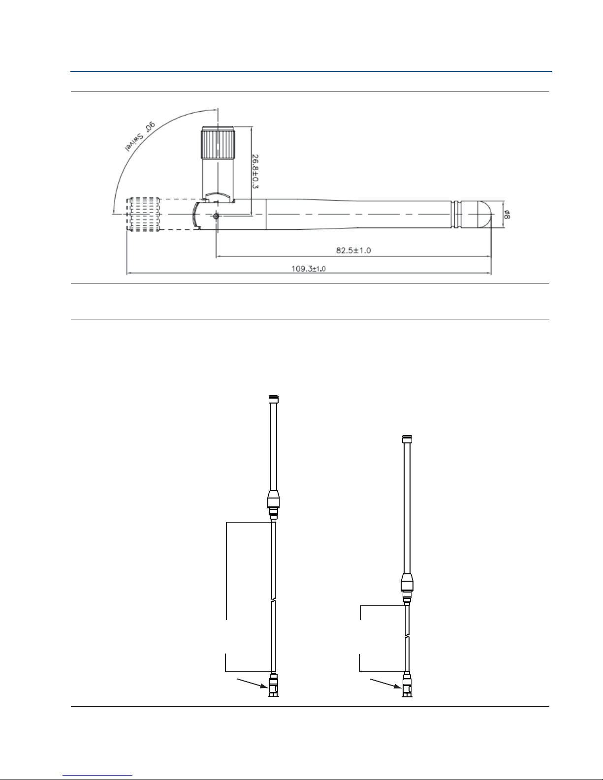
Appendix A: Product Specifications
Antenna
50 ft. (15,2 m)
cable
Lightning
Arrestor
WL2WL2
Antenna
25 ft. (7,6 m)
cable
Lightning
Arrestor
WN2WN2
February 2014
Figure A-2. WX2 Basic Antenna Dimensions
Dimensions are in millimeters.
Reference Manual
00809-0200-4410, Rev BA
Figure A-3. Remote Omni-antenna Kit
The remote omni-antenna kit includes sealant tape for remote antenna connection, SMA to N-type adapter cable, mounting
brackets for the antenna, and lightning arrester.
62
Product specifications
Page 71
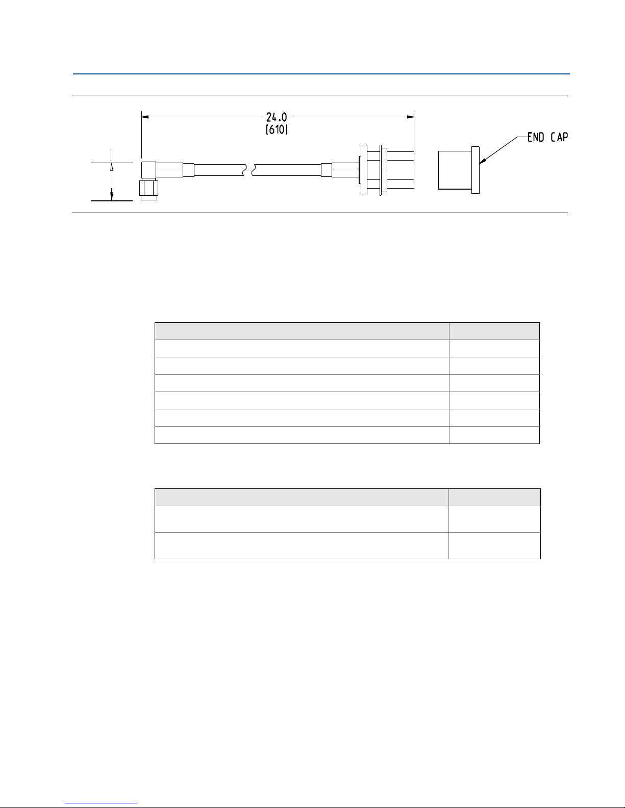
Reference Manual
.650
[16,51]
00809-0200-4410, Rev BA
Figure A-4. SMA to N-Type Adapter Cable Dimensions
Dimensions are in inches (millimeters).
A.8 Accessories and spare parts
Table A-2. Accessories
Item description Part number
Appendix A: Product Specifications
February 2014
AMS Wireless SNAP-ON™, 1 Gateway License 01420-1644-0001
AMS Wireless SNAP-ON, 5 Gateway Licenses 01420-1644-0002
AMS Wireless SNAP-ON, 10 Gateway Licenses 01420-1644-0003
AMS Wireless SNAP-ON, 5-10 Upgrade Licenses 01420-1644-0004
Serial Port HART Modem and Cables only 03095-5105-0001
USB Port HART Modem and Cables only 03095-5105-0002
Table A-3. Spare Parts
Item description
Spare Kit, WL2 Replacement
Remote Antenna, 50 ft. (15,2 m) Cable, and Lightning Arrestor
Spare Kit, WN2 Replacement
High Gain, Remote Antenna, 25 ft. (7.6 m) Cable, and Lightning Arrestor
(1) Does not include SMA to N-type adapter.
(2) Can not upgrade from integral to remote antenna.Replacement Kits must be matched to original antenna type to maintain
telecommunication approvals. I.e. WN2 cannot replace a WL2.
(1)
Part number
(2)
,
(2)
,
01420-1615-0302
01420-1615-0402
Product specifications
63
Page 72

Page 73

Reference Manual
00809-0200-4410, Rev BA
Appendix B: Product Certifications
Appendix B Product Certifications
Approved Manufacturing Locations . . . . . . . . . . . . . . . . . . . . . . . . . . . . . . . . . . . . . . . . . . . page 65
Telecommunication Compliance . . . . . . . . . . . . . . . . . . . . . . . . . . . . . . . . . . . . . . . . . . . . . . page 65
FCC and IC . . . . . . . . . . . . . . . . . . . . . . . . . . . . . . . . . . . . . . . . . . . . . . . . . . . . . . . . . . . . . . . . . page 65
European Directive Information . . . . . . . . . . . . . . . . . . . . . . . . . . . . . . . . . . . . . . . . . . . . . . . page 65
Ordinary Location Certification from FM Approvals . . . . . . . . . . . . . . . . . . . . . . . . . . . . . . page 65
Hazardous Locations Certifications . . . . . . . . . . . . . . . . . . . . . . . . . . . . . . . . . . . . . . . . . . . . page 66
B.1 Approved Manufacturing Locations
Rosemount Inc. - Chanhassen, Minnesota, USA
Emerson Process Management Asia Pacific Private Limited - Singapore
February 2014
B.2 Telecommunication Compliance
All wireless devices require certification to ensure that they adhere to regulations regarding the
use of the RF spectrum. Nearly every country requires this type of product certification.
Emerson is working with governmental agencies around the world to supply fully compliant
products and remove the risk of violating country directives or laws governing wireless device
usage.
B.3 FCC and IC
This device complies with Part 15 of the FCC Rules. Operation is subject to the following
conditions: This device may not cause harmful interference. This device must accept any
interference received, including interference that may cause undesired operation. This device
must be installed to ensure a minimum antenna separation distance of 20 cm from all persons.
B.4 European Directive Information
The EC declaration of conformity can be found on page xx. The most recent revision can be
found at www.emersonprocess.com.
B.5 Ordinary Location Certification from FM
Approvals
As standard, the transmitter has been examined and tested to determine that the design meets
basic electrical, mechanical, and fire protection requirements by FM Approvals, a nationally
recognized testing laboratory (NRTL) as accredited by the Federal Occupational Safety and
Health Administration (OSHA).
Product Certifications
65
Page 74

Appendix B: Product Certifications
February 2014
B.6 Hazardous Locations Certifications
North America
N5 FM Approvals, Nonincendive for Class I Division 2
Certificate: 3049590
Standards Used: Class 3600:2011, Class 3611:2004, Class 3810:2005
Markings: NI CL I, DIV. 2, GP A, B, C, D
Temperature code: T4 (-40 °C
Special Condition for Safe Use:
1. When installed as Division 2 equipment, the 1410 shall be mounted within a
tool-secured enclosure which meets the requirements of ANSI/ISA 61010-1 and be
capable of accepting the applicable wiring methods per the NEC.
N6 CSA Class I Division 2
Certificate: 2646342
Standards Used: CSA Std. C22.2 No. 0-10, CSA Std. C22.2 No. 213 - M1987, CSA Std.
C22.2 No.61010-1-12, ANSI/ISA 12.12.01-2012, ANSI/ISA 61010-1-2012
Markings: SUITABLE FOR CL I, DIV. 2, GP A, B, C, D
Temperature code: T4 (-40 °C
Ta 60 °C)
Ta 70 °C)
Reference Manual
00809-0100-4021, Rev BA
NOTE
Shall be powered by a class 2 power supply.
Suitable for dry indoor locations only.
Equipment must be installed in a suitable tool accessible enclosure subject to the end
use application.
66
Product Certifications
Page 75

Page 76

Reference Manual
00809-0200-4410, Rev BA
February 2014
Standard Terms and Conditions of Sale can be found at www.rosemount.com/terms_of_sale
The Emerson logo is a trademark and service mark of Emerson Electric Co.
Rosemount. the Rosemount logotype, and SMART FAMILY are registered trademarks of Rosemount Inc.
Coplanar is a trademark of Rosemount Inc.
Halocarbon is a trademark of the Halocarbon Products Corporation.o.
Fluorinert is a registered trademark of Minnesota Mining and Manufacturing Company Corporation
Syltherm 800 and D.C. 200 are registered trademarks of Dow Corning Corporation.
Neobee M-20 is a registered trademark of PVO International, Inc.
HART is a registered trademark of the HART Communication Foundation.
Foundation fieldbus is a registered trademark of the Fieldbus Foundation.
All other marks are the property of their respective owners.
© February 2014 Rosemount, Inc. All rights reserved.
Emerson Process Management
Rosemount Measurement
8200 Market Boulevard
Chanhassen MN 55317 USA
Tel (USA) 1 800 999 9307
Tel (International) +1 952 906 8888
Fax +1 952 906 8889
Emerson Process Management
Latin America
1300 Concord Terrace, Suite 400
Sunrise Florida 33323 USA
Tel + 1 954 846 5030
Emerson Process Management
GmbH & Co.
Argelsrieder Feld 3
82234 Wessling
Germany
Tel 49 (8153) 9390
Fax 49 (8153) 939172
Emerson Process Management Asia
Pacific Private Limited
1 Pandan Crescent
Singapore 128461
T (65) 6777 8211
F (65) 6777 0947
[email protected]
Beijing Rosemount Far East
Instrument Co., Limited
No. 6 North Street,
Hepingli, Dong Cheng District
Beijing 100013, China
T (86) (10) 6428 2233
F (86) (10) 6422 8586
 Loading...