


026-1012 Rev 3 06-DEC-2011
Site Manager User Manual


Retail Solutions
3240 Town Point Drive NW Suite 100
Kennesaw, GA 30144
Phone: 770-425-2724
Fax: 770-425-9319


Table of Contents
1 OVERVIEW................................................................................................................................................................... 1
1.1. W
1.2. B
HAT SITE MANAGER CAN DO................................................................................................................................... 1
ASIC CONCEPTS.......................................................................................................................................................... 1
1.2.1. Search Criteria...................................................................................................................................................... 1
1.2.1.1. Tips for Narrowing Your Search Criteria............................................................................... .... ........................................ 2
1.3. QUICK START ............................................................................................................................................................... 3
1.3.1. Overview ............................................................................................................................................................... 3
1.3.2. Supported Browsers.............................................................................................................................................. 3
1.3.3. Launching Site Manager....................................................................................................................................... 3
1.4. L
OGIN/LOGOUT ............................................................................................................................................................ 3
1.4.1. Login..................................................................................................................................................................... 3
1.4.2. Logout................................................................................................................................................................... 4
1.5. S
ITE MANAGER INTERFACE.......................................................................................................................................... 5
1.5.1. Navigation Tree..................................................................................................................................................... 6
1.5.2. Navigation Window............................................................................................................................................... 6
1.5.3. Menu Bar............................................................................................................................................................... 7
1.5.4. Main Window........................................................................................................................................................ 7
2 IT ADMINISTRATOR FUNCTIONS......................................................................................................................... 8
2.1. F
EATURE LICENSING AND REGISTRATION.................................................................................................................... 8
2.1.1. Registration........................................................................................................................................................... 8
2.1.2. Activation............................................................................................................................................................ 10
2.1.3. Licensing............................................................................................................................................................. 11
2.1.4. Maintenance Upgrades & Tech Support Licensing............................................................................................ 11
2.1.4.1. About Maintenance Upgrades & Tech Support Licensing and Keys............................................................................... 11
2.1.4.2. About Feature Licensing and Keys................................................................................................................................... 12
2.2. DATABASE BAC KUP.................................................................................................................................................... 12
2.3. I
MPORTING XML DATAFILE....................................................................................................................................... 12
2.3.1. Default Time Zone During Import...................................................................................................................... 13
2.4. T
ROUBLESHOOTING .................................................................................................................................................... 13
2.4.1. Page Troubleshooting......................................................................................................................................... 13
2.4.1.1. Online Help Navigation - Pop-up Window Scrolling in Online Help.............................................................................. 13
2.4.2. Error Report........................................................................................................................................................ 13
3 MENUS......................................................................................................................................................................... 14
3.1. M
Y INFO MENU.......................................................................................................................................................... 14
3.1.1. About User Info................................................................................................................................................... 14
3.1.2. User Info ............................................................................................................................................................. 14
3.1.3. My Pending Activities ......................................................................................................................................... 15
3.1.4. My Activity History ............................................................................................................................................. 15
3.2. A
DMIN TOOLS MENU ................................................................................................................................................. 17
3.2.1. Setup.................................................................................................................................................................... 17
3.2.1.1. User Manager.................................................................................................................................................................... 17
3.2.1.2. Group Manager................................................................................................................................................................. 19
3.2.1.3. Directory Manager............................................................................................................................................................ 21
3.2.1.4. Site Manager..................................................................................................................................................................... 22
3.2.1.5. Contractor Manager.......................................................................................................................................................... 23
3.2.2. Pending Activities ............................................................................................................................................... 24
3.2.3. Admin Activity History........................................................................................................................................ 24
Table of Contents • v

3.2.3.1. View History..................................................................................................................................................................... 24
3.2.3.2. Configure Purge................................................................................................................................................................ 26
3.2.4. Schedule Manager............................................................................................................................................... 26
3.2.4.1. Setting Up User Schedules............................................................................................................................................... 26
3.2.4.2. User Schedules.................................................................................................................................................................. 28
3.2.4.3. Filtering Rules................................................................................................................................................................... 30
3.2.5. Send Email........................................................................................................................................................... 31
3.3. A
CTIVITIES MENU....................................................................................................................................................... 31
3.3.1. Advisory Menus................................................................................................................................................... 31
3.3.1.1. Connection Verification Report........................................................................................................................................ 31
3.3.1.2. Purge Inbound Connections.............................................................................................................................................. 31
3.3.1.3. Advisory Forwarding........................................................................................................................................................ 32
3.3.2. Setpoint Broadcast.............................................................................................................................................. 32
3.3.2.1. Schedules Setup................................................................................................................................................................ 35
4 NAVIGATION TREE.................................................................................................................................................. 37
4.1. U
SING THE NAVIGATION TREE................................................................................................................................... 37
4.2. D
IRECTORY................................................................................................................................................................. 38
4.2.1. Add Site ............................................................................................................................................................... 38
4.2.2. Add Directory...................................................................................................................................................... 38
4.2.3. Directory Properties ........................................................................................................................................... 39
4.2.4. Delete Directory .................................................................................................................................................. 39
4.2.5. Edit/Configure Directory.................................................................................................................................... 39
4.3. S
ITE............................................................................................................................................................................. 40
4.3.1. Add Control System............................................................................................................................................. 40
4.3.2. Delete Site ........................................................................................................................................................... 40
4.3.3. Edit/Configure Site.............................................................................................................................................. 41
4.3.4. Site Properties..................................................................................................................................................... 41
4.4. C
ONTROL SYSTEM ...................................................................................................................................................... 41
4.4.1. Control System Properties .................................................................................................................................. 42
4.4.2. Delete Control System......................................................................................................................................... 42
4.4.3. Edit/Configure Control System........................................................................................................................... 42
4.4.3.1. Advisory Receiver Commission....................................................................................................................................... 43
4.5. UNIT............................................................................................................................................................................ 43
4.5.1. Unit Properties.................................................................................................................................................... 43
4.5.2. Add Application Instance.................................................................................................................................... 44
4.5.3. Delete Application Instance................................................................................................................................ 44
4.5.4. Edit Application Instance.................................................................................................................................... 45
4.5.5. Application Type Properties................................................................................................................................ 48
4.5.6. Application Instance Properties .......................................................................................................................... 48
4.6. E
XECUTING ACTIVITIES .............................................................................................................................................. 49
4.6.1. Backup................................................................................................................................................................. 49
4.6.2. Initializing Terminal Mode.................................................................................................................................. 49
4.6.2.1. Terminal Mode Keys (E2 Controller Type Shown)......................................................................................................... 50
4.6.3. Obtain Controller Information............................................................................................................................ 50
4.6.4. Refresh Application............................................................................................................................................. 51
4.6.5. Refresh Point List................................................................................................................................................ 51
4.6.6. Refresh Units....................................................................................................................................................... 52
4.6.7. Restore................................................................................................................................................................. 52
4.6.8. Retrieve Logs....................................................................................................................................................... 52
4.6.9. Upload Description File...................................................................................................................................... 53
4.6.9.1. Description File Upload to the E2 Controller................................................................................................................... 54
4.6.10. Create Setpoint Broadcast ................................................................................................................................ 54
5 FIRMWARE UPDATE ............................................................................................................................................... 56
vi • Site Manager User Manual 026-1012 Rev 3 06-DEC-2011

5.1. FIRMWARE PACKAGE MANAGEMENT......................................................................................................................... 56
5.1.1. Add Firmware..................................................................................................................................................... 56
5.1.2. Delete Firmware................................................................................................................................................. 58
5.2. F
IRMWARE UPDATE TRANSFER .................................................................................................................................. 59
5.2.1. Downgrading Firmware ..................................................................................................................................... 61
5.2.2. Firmware Update Transfer Interruption............................................................................................................. 61
5.3. F
IRMWARE UPDATE APPLY ........................................................................................................................................ 62
5.3.1. Firmware Apply Deployment.............................................................................................................................. 62
5.3.2. Firmware Matching and Activity History Role................................................................................................... 63
5.3.3. Downgrades and Setpoint Clean-Out................................................................................................................. 64
5.3.4. Non-Gateway Controllers First, Gateway Last.................................................................................................. 64
5.3.5. Firmware Matching............................................................................................................................................ 64
5.3.6. Successful or Failed Results ............................................................................................................................... 64
6 ADVISORIES............................................................................................................................................................... 65
6.1. L
IVE ADVISORY VIEW................................................................................................................................................ 65
6.1.1. Navigation ........................................................................................................................................................... 65
6.1.2. Filtering .............................................................................................................................................................. 67
6.2. H
ISTORICAL ADVISORY VIEW.................................................................................................................................... 68
6.2.1. Connection Verification Report.......................................................................................................................... 70
6.2.1.1. Setting Up a Problem Sites Report Email (Administrators Only).................................................................................... 70
6.2.2. Purge Inbound Connections................................................................................................................................ 71
6.2.3. Advisory Forwarding.......................................................................................................................................... 72
6.2.4. Advisory Receiver Commissioning...................................................................................................................... 72
7 CONFIGURATION ..................................................................................................................................................... 74
7.1. C
ONFIGURING ACTIVITIES .......................................................................................................................................... 74
7.1.1. Configure Advisory Purge.................................................................................................................................. 74
7.1.2. Advisory Snooze Configuration .......................................................................................................................... 74
7.1.3. Configure Backup ............................................................................................................................................... 75
7.1.4. Configure Log Purge .......................................................................................................................................... 75
7.2. C
ONFIGURATION TOOLS............................................................................................................................................. 77
7.2.1. List Power Builder.............................................................................................................................................. 77
7.2.1.1. Bulk Site Name Report..................................................................................................................................................... 78
8 POINTS......................................................................................................................................................................... 79
8.1. O
VERVIEW.................................................................................................................................................................. 79
8.2. P
OINT PROPERTIES...................................................................................................................................................... 80
8.3. W
ATCH OR GRAPH LOG POINTS................................................................................................................................. 81
8.3.1. Graph Log Points While Viewing a GS Screen................................................................................................... 82
8.4. D
ISPLAY LOG GRAPH ................................................................................................................................................. 83
8.4.1. Graphing Range.................................................................................................................................................. 83
8.4.2. Site Time or My Time.......................................................................................................................................... 83
9 GRAPHICAL STATUS SCREENS/FLOOR PLANS.............................................................................................. 85
9.1. O
VERVIEW.................................................................................................................................................................. 85
9.1.1. Generic GS Screens ............................................................................................................................................ 85
9.1.2. Show GS Screen Edit Tool Checkbox - My User Info Page................................................................................ 85
9.2. Q
UICK START ............................................................................................................................................................. 86
9.2.1. Create GS Screens Quick Start........................................................................................................................... 86
9.2.2. Run and Edit Modes............................................................................................................................................ 86
9.2.3. Widgets and Images............................................................................................................................................ 87
9.2.4. Setting a GS Screen as Your Home Page............................................................................................................ 87
9.2.5. JSON Source Code.............................................................................................................................................. 87
Table of Contents • vii

9.2.6. Working With Widget Parameters....................................................................................................................... 87
9.3. GS S
CREEN ACTIONS.................................................................................................................................................. 87
9.3.1. Exporting the GS .ZIP......................................................................................................................................... 87
9.3.2. Saving the GS...................................................................................................................................................... 88
9.3.3. Delete the GS....................................................................................................................................................... 89
9.3.4. Associating the GS Screen................................................................................................................................... 89
9.3.5. Disassociate the GS Screen................................................................................................................................. 90
9.3.6. Importing GS Screen (.ZIP) ................................................................................................................................ 90
9.3.6.1. Import Results................................................................................................................................................................... 91
9.3.7. Properties of the GS............................................................................................................................................ 91
9.4. W
IDGETS AND CREATING GS S CREENS ..................................................................................................................... 92
9.4.1. Adding GS Screens.............................................................................................................................................. 92
9.4.1.1. Create GS Screens Quick Start......................................................................................................................................... 93
9.4.1.2. The Add Widgets Palette.................................................................................................................................................. 93
9.4.1.3. Creating a Text-Only Label Widget Quick Start.............................................................................................................. 93
9.4.1.4. Point References............................................................................................................................................................... 93
9.4.1.5. Visibility ........................................................................................................................................................................... 94
9.4.1.6. Widget Properties ............................................................................................................................................................. 94
9.4.1.7. More Widget Editing........................................................................................................................................................ 95
9.4.1.8. GS Image Property Editor................................................................................................................................................. 95
9.4.1.9. Common Properties .......................................................................................................................................................... 96
9.4.1.10. Widget Screen Linking................................................................................................................................................... 97
9.4.1.11. Image Library................................................................................................................................................................ 101
9.4.2. Running GS Screens.......................................................................................................................................... 103
9.4.2.1. Widget GS Right-Click Menu Options........................................................................................................................... 103
9.4.2.2. My System Home Page................................................................................................................................................... 103
9.4.2.3. Setting a GS Screen as Your System Home Page........................................................................................................... 103
9.4.2.4. Setting a GS Screen as Your Site Home Page................................................................................................................ 104
9.4.2.5. Edit and Run Modes and Supported Browsers............................................................................................................... 104
9.4.2.6. Print Icon......................................................................................................................................................................... 104
9.4.2.7. Logout Button................................................................................................................................................................. 104
9.4.3. Widget Editor.................................................................................................................................................... 104
9.4.3.1. Edit and Run Modes ....................................................................................................................................................... 105
9.4.4. Widget Parameters - Customization................................................................................................................. 105
9.4.4.1. Point Status Information................................................................................................................................................. 106
9.4.4.2. Point Reference Information........................................................................................................................................... 108
9.4.4.3. Locale Resource Message Keys...................................................................................................................................... 109
9.4.4.4. Screen Information Parameters....................................................................................................................................... 109
9.4.4.5. Miscellaneous Parameters............................................................................................................................................... 112
9.4.5. Summary Screen Widget.................................................................................................................................... 112
9.4.5.1. Widget Behavior............................................................................................................................................................. 113
9.4.5.2. Properties Menu.............................................................................................................................................................. 113
9.4.5.3. Points, Headers, Values.................................................................................................................................................. 114
10 REVISION HISTORY............................................................................................................................................. 115
INDEX........................................................................................................................................................................... 117
viii • Site Manager User Manual 026-1012 Rev 3 06-DEC-2011

1Overview
1.1. What Site Manager Can
Do
Site Manager helps you manage and monitor site
information and activities by giving you fast, remote
access and intuitive navigational tools.
It also allows users to gain immediate access to
data for perf orming and configu ring si te acti vities for
superior task control and site management.
Get your data fast and accurately by:
• Restoring setpoints
• Viewing activity history
• Finding activities that are pending
• Backing up site information
• Refreshing units
• Creating a history of an applicati on’s inputs an d outputs
• Executing point tasks
• Remotely logging into a unit using Terminal Mode
technology
• Creating and designing your own floor plans
• Viewing Historical Advisories
• Receiving Live Advisories
• Configuring backups and other activities
• Broadcasting Setpoints
• Scheduling Activities
Site, Control System, and Unit, and use the Search
option (see Section 1.2.1., Sear ch Criter ia) for locat ing items in S ite Manager.
Site Manager features include:
• Site Creation
• Basic Site Management (navigation tree view,
grouping of sites, site visibility)
• Backup/Restore (backup all sites, daily schedules
backup)
• TCP/IP Connectivity Only
• Historical and Live Advisory Views
• Terminal Mode (viewing the front panel remotely)
• Data Acquisition (log retrieval/archiving, graphing,
export to spreadsheet)
• User Management (user access, admin functions,
site security, ability to limit user operations)
• Schedule Activities
• Firmware Update
• View GS Screens
1.2.1. Search Criteria
A search can be per formed by entering crite ria into
the Search field on the main window (see Section
1.5., Site Manager Interface for its location).
Searches can be performed for directories, sites,
control systems, units, applications, points, contractors, users, menus, and help items.
An attempt is first made to match ALL words
searched for. If no results are returned, alternative
word suggestions are provided.
Twenty (20) results ar e shown per pa ge. Prev and
Next links appear and show previ ous and next pag es.
Search results appear based on how c lose th ey match
the criteria entered.
1.2. Basic Concepts
Using the Site Manager us er interface, you can log
in, log out, backup and restor e site s, add, ed it, del ete,
maintain sites and control systems, view all activities
on a status page, access help files, and access log information in the controller depending on licensing
and how privileges are set for each user. Navigate
through Site Manager by using the navigation tree,
which comprises four levels, or “nodes”: Directory,
What Site Manager Can Do Overview • 1
Directory
To search for a directory, the following criteria
can be entered: Name of directory, city, state code,
state name, country code, country name.

Sites
To search f or a site, the following criteria can be
entered: Name of sit e (numerics are supported: for ex ample, you can search for “Store Name 10”, even if
the actual name is “Store Name 00010”), city, state
code, state name, country code, country name.
Control System
To search f or a control system, the following cri-
teria can be entered: Name of control system, protocol, IP Address, site alias.
Unit
To search for a unit, the following criteria can be
entered: Name of the unit, type, firmware version.
Application Type
To search f or a application type, the following
criteria can be entered: Name of the application type.
Application Instance
To search f or a application instance, the follow-
ing criteria can be entered: Name of the application
instance.
Point
To search for a point, the following criter ia can be
entered: Name of point.
Contractor
To search f or a contractor, the following criteria
can be entered: Name of the cont ractor, e-mail, phone,
city, state code, state name, country code, country
name.
User
To search for a user, the following criteria can be
entered: Name of the user , user’s role, fir st name, last
name, e-mail, display name, username.
Menu
To search for menu, the following crit eria can be
entered: Menu names.
Help
To search f or help, the following criteria can be
entered: Help contents.
1.2.1.1. Tips for Narrowing Your Search
Criteria
You can generally search f or the entity type by just
typing it in. For example, if you search for site 120, a
list of sites with 120 in its name will be returned.
Searching for Store 120 will also return similar re-
sults. In addition to this feature, you may narrow
down the search more specif ically by using narrowed
criteria.
You may prefix a word with a scope to narrow it
down. The prefix must be fol lowed by a colon (:) and
then the search word. For example, site:Robert - this
criteria will return sites that have Robert in the site
search scope, but not director ies, users, contractors, or
control systems that have Robert in their search
scopes. Table 1-1 lists the allowed prefixes.
Prefix Search Scope
dir limits searches to directories
site limits searches to sites
cs limits searches to control systems
contractor limits searches to contractors
user limits searches to users
name limits searches to names of entities
city limits searches to city names
statecode limits searches to state codes of enti-
ties
statename limits searches to state names of enti-
ties
countrycode limits searches to country codes of en-
tities
country limits searches to country names of
entities
help limits searches to help items
menu limits searches to menu items
role limits searches to role name
firstname limits searches to first name of enti-
ties
lastname limits searches to last name of entities
email limits searches to e-mail addresses
display name limits searches to display name of en-
tities
unittype limits searches to unit types
2 • Site Manager User Manual 026-1012 Rev 3 06-DEC-2011
Table 1-1 - Allowed Prefixes to Narrow Down Search Criteria
Prefix Search Scope
revision limits searches to unit version
protocol limi ts search es to prot oco l names
ip limits searches to IP addresses
1.4. Login/Logout
1.4.1. Login
Table 1-1 - Allowed Prefixes to Narrow Down Search Criteria
NOTE: A prefix cannot be used with another.
For example, the following is not supported:
contractor:name:Robert
1.3. Quick Start
1.3.1. Overview
In this section you will find step-by-step instructions on how to log in to Site Manager, set up the navigation tree, user access, and communication
information. From the navigation tree you can connect to controllers, set up directory, site, control system, and unit information.
1.3.2. Supported Browsers
Note that IE 7 and above and the latest version of
Firefox (off the Firefox Web site) are the supported
browsers. (IE 6 is supported for viewing GS screens
only.)
1.3.3. Launching Site Manager
To begin using Site Manager, open a Web browser
(IE 7 and above and the latest vers ion of Firefox (off
the Firefox Web site) are the supported browsers. IE
6 is supported for viewing GS screens only):
If running the same computer on which Site Manager was installed, type http://localhost/emerson inside the browser field. If running the program from
another computer, use the machine name or IP address instead of localhost. The Site Manager Enter-
prise program will open.
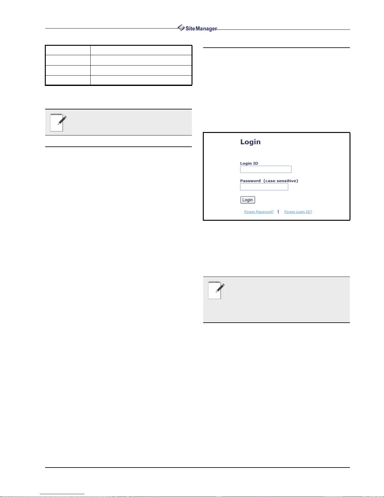
The login page is the first page that appears on
your web browser (Figu re 1-1). Enter your Login ID
and password into their respective fields (the Pass-
word field is case sensitive) and press the Login button or press Return on your keyboard.
Figure 1-1 - Login Page
Once your login has been validated, you will be
taken to the Home page where t he page i s made up of
the navigation tree and main information window.
NOTE: For first-time users using the default
login credentials, it is strongly recommended
that you rename the Login ID and change the
password as soon as the program is installed
and running so that duplicate login names and passwords do not occur.
First-time users wil l be prese nted wit h the li cense
agreement window. The “I Agree” button must be
clicked in order to begin using the application.
You can begin using Site Manager by:
• creating a directory structure
• setting up users (optional)
Quick Start Overview • 3
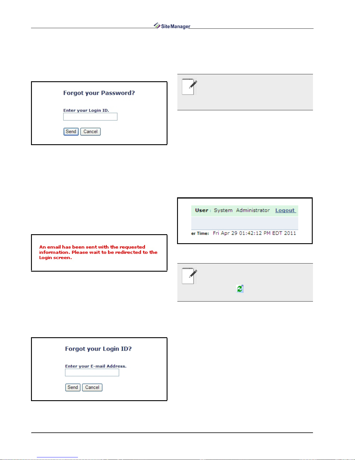
To retrieve a password that has been forgotten,
click on the Forgot Password? link to open a special
ID window (Figure 1-2) where you can enter your
login ID and have your password sent to the e-mail
address associated with your login ID.
Figure 1-2 - Forgot your Password? Window
1. Enter your valid login ID and click Send.
2. Your passwor d is changed to a random password
that consists of 8 characters when the ID is entered.
3. The changed password will be sent to the e-mail address associated with your login ID.
4. Site Manager will show an information (Figure 1-
3) to let you know that an e-mail was sent containing new password informatio n and redi rects you to
the Login screen after 5 seconds.
1. Enter your valid e-mail address and click Send.
2. Your login ID(s) will be sent to the e-mail you entered.
NOTE: If no e-mail address was assigned
when your user profile was initially set up, you
will be shown a message stating that there is no
e-mail address associated with your Login ID.
Contact your IT administrator.
If you are unable to log in, check th e following:
• Incorrect ID/Password combination was entered
• Login ID has expired
• Case sensitivity was not observed when entering
password
1.4.2. Logout
To log out at any time, cl ick Logout located at the
top right corner of the main window(Figure 1-5):
Figure 1-3 - New Password Confirmation
To retrieve a login ID that has been forgotten,
click on the Forgot your Login ID? link to open a
special ID window (Figure 1-4 ) where yo u can en ter
your E-mail Address and have your Site Manager
Login ID sent to the e-mail address associated with
your login ID.
Figure 1-4 - Forgot your Login ID? Window
Figure 1-5 - Logout link
NOTE: You will be logged out when Site Manager is idle for a set amount of time (determined by the administra tor). Click t he browser
Refresh button to automatically log out and
return to the login screen.
4 • Site Manager User Manual 026-1012 Rev 3 06-DEC-2011
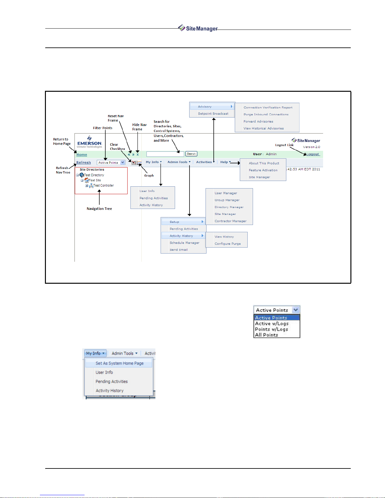
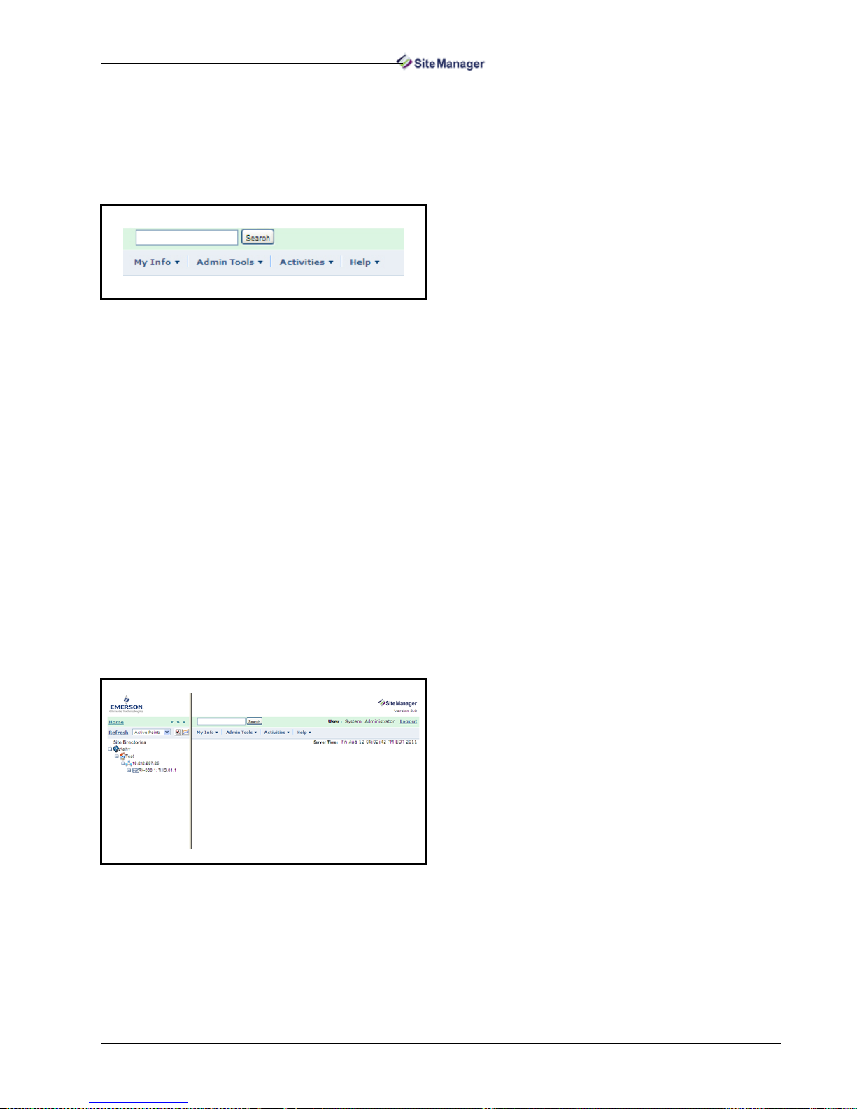
1.5. Site Manager Interface
The Site Manager page (Figure 1-6) is where you will find the navigation tree, navigation window, menu
bar, and the main window.
Figure 1-6 - Site Manager Interface Page
The following are the window menu and tools
found on the page:
• Home - System Home returns you to the main page
or to a customized location that can be s et on the My
Info menu:
• Refresh - Refreshes t he navigation window . If your
session has timed out, it will return you to the Login
page.
• Filter Points - Allows you to display different point
views in the navigation window. Select from the
drop-down list for the appropriate point view.
• Active Points is the default each time the user
starts up the browser and will show all configured points in the controller.
• Active with Logs shows active points that have
a controller log available.
• Points with Logs shows points that have a controller log available.
• All Points shows all possible points for an application instance, whether a point is configured or
not. An icon will appear next to the point if the
point has a log.
• Navigation Tree - The m ain descending “tree” view
Site Manager Interface Overview • 5
of all directories, sites, units, and control systems.
• Navigation Window - The main window of the
navigation tree.
• Hide Navigation Frame - Collapses or hides the
navigation window from view, allowing for maximum viewing room of the main window. Click on
the Site Manager icon adjacent to the Search
field to show the navigation window.
• Reset Navigation Fram e - Restores the navigation
window to its original size after being collapsed.
• Clear Checkboxes - Clears all point checkboxes in
the navigation tree.
• Graph - Graphs the selected point.
• Refresh - Refreshes t he navigation window . If your
session has timed out, it will return you to the Login
page.
• Main Window - The main workspace window of
Site Manager.
• My Info - Displays user-related information.
• Admin Tools - Displays administrator-level fea-
tures such as setup, pending activities, activity history, schedule manager, and send email.
• Activities - Displays menus for various activities
such as Advisory and Setpoint Broadcast. Help
Menu - Displays the menu for the online help and
feature activation page. Depending on user settings,
click Site Manager to open Site Manager Onlin e
Help.
• Advisory Alert Icon - When an advisory has been
received, the alert icon will display on the interface
depending on the user’s permissi on s. Users can see
the alert icon from anywhere in Site Manager. Click
on the alert icon to go to the Historical Advisory
View page and see the advisory history.
• Search - Find directories, sit es, cont rol syst ems, us ers, contractors, and more by entering your search
criteria in the field. For more information on performing searches in Site Manager, refer to Section
1.2., Basic Concepts.
• Logout - Logs you out of Site Manager.
and units. The appl ications are l ocated next to the box
icons, with any applicat ion instance li sted underneath
the box next to the application instance icons. Application instance are use r-d ef ine d and can be of one or
more in quantity.
NOTE: See Section 4, Navigation Tree for
more information about the Site Manager navigation tree.
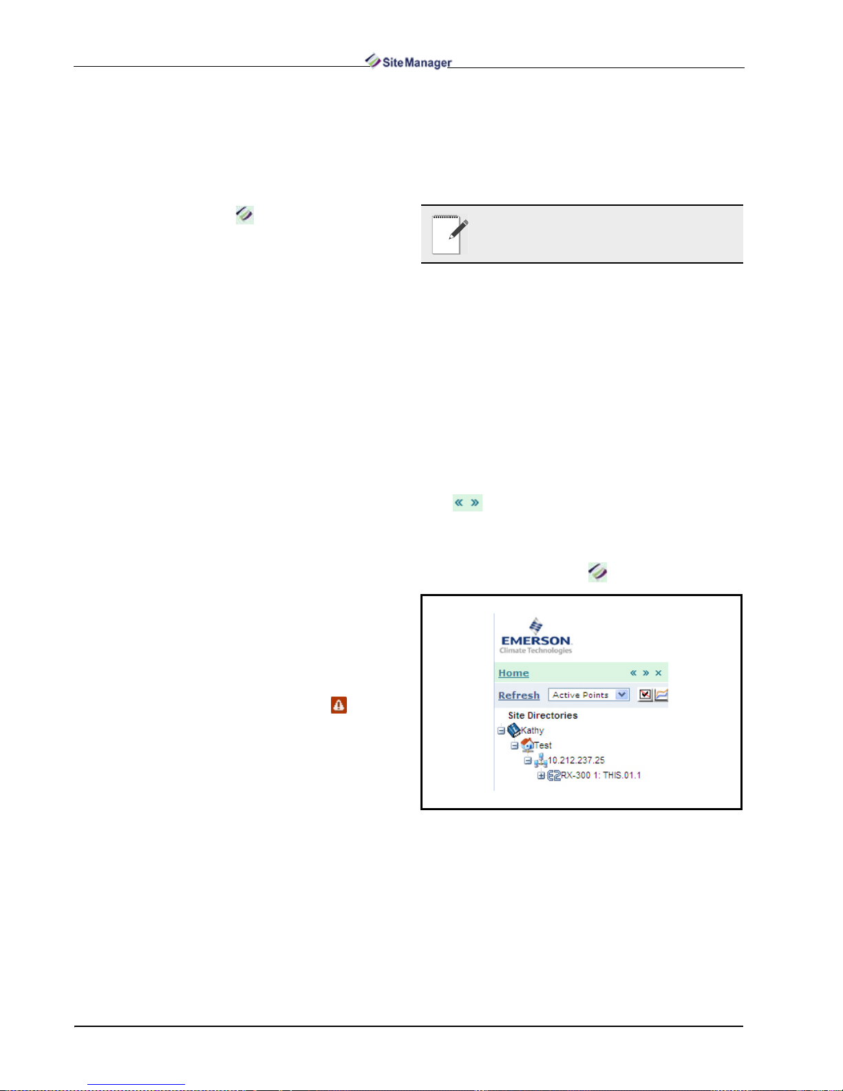
1.5.2. Navigation Window
The navigation window comprises the navigation
tree (located on the left-hand side of the screen) and is
the first screen the use r will see once lo gged into Site
Manager.
The Home button is located under the logo and
will always take the user back to the Home page.
Click the “x” (Hide Nav Frame button) to mini-
mize the navigation windo w so only the main window
can be seen. Click the Reset Nav Frame button to
size the navigation frame window back to the de-
fault.
Click the Show Nav Frame button to maximize
the navigation window again ( visible aft er the navi ga-
tion window is minimized).
Figure 1-7 - Navigation Window
1.5.1. Navigation Tree
The navigation tree is located on the left-hand side
of the screen insi de the na vigat ion wind ow and is t he
first screen the user will see.
The navigation tree comprises four levels: Directories, Sites, Control Systems, and Unit s. The navigation tree will load directories, sites, control systems,
6 • Site Manager User Manual 026-1012 Rev 3 06-DEC-2011
1.5.3. Menu Bar
Depending on licensing and the ass igned use r level, the menu bar gives you acc ess to menu items such
as Pending Activiti es, Activity Histori es, Groups, and
online help:
Figure 1-8 - Menu Bar
• To access your Pending Activities and your Activity
History, click on My Info for the drop-down menu.
• To access Groups, click on Admin Tools for the
drop-down menu (this menu can only be accessed
by admin level users).
• To access advisory menus and setpoint broadcast,
click on Activities for the drop-down menu.
• To access the online help system, click Help for the
drop-down menu.
1.5.4. Main Window
The main window of the Site Manager is located
to the right of th e Navigation fr ame and takes up most
of the space on the screen. Mouse over the name of
the menu you would like to select and the drop -down
menu will appear. Select the desired menu item by
clicking on it. This will open the page in the main
window followed by the links.
Figure 1-9 - Main Window
Site Manager Interface Overview • 7
2 IT Administrator
Functions
2.1. Feature Licensing and
Registration
Site Manager has b asi c a nd ex tra features that ar e
activated by obtaining a license. To obtain trial and
other licensing, you must first register the software.
A license key must be entered to activate the desired featu re. A Maintenance Upgrad es & Tech Sup-
port license key activates basic features and the
feature license keys activate special Site Manager
plug-in features. Keys are entered when the program
is first start ed.
The software feature activation page is accessible
from the Help drop-down menu. The Feature Acti-
vation menu item will only be visible with certain
user privileges enabled that will allow software license keys to be added/edited.
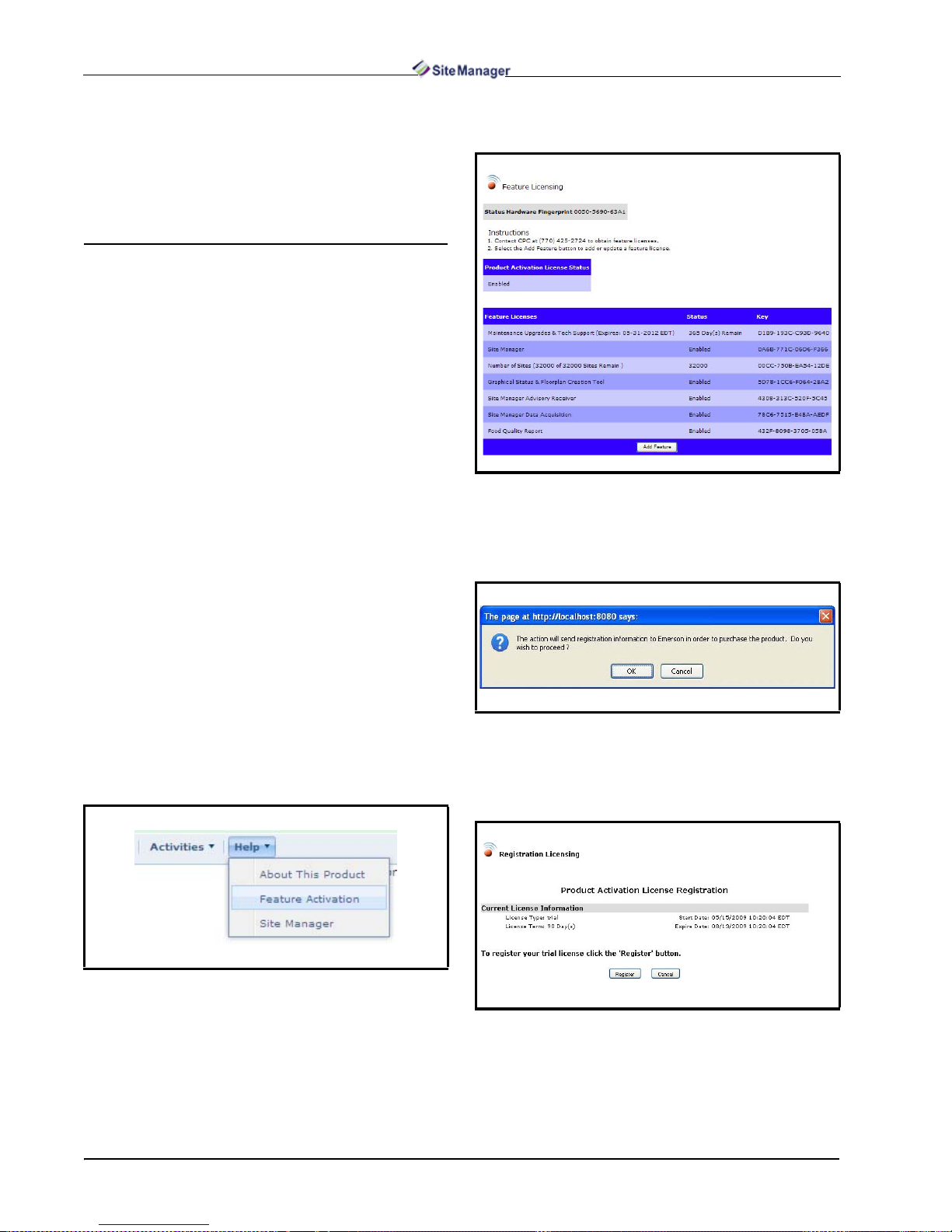
2. Click the Registration button to proceed in obtain-
ing a license.
Figure 2-2 - Feature Licensing Page
3. Click OK to open the Product Activation License
Registration page. The state of the current license is
displayed on this page:
The Site Manager Feature Licensing window dis-
plays what type of fe atu re is lice nsed, t he lic ense ke y
number, and license status.
2.1.1. Registration
1. Click the Help drop-down menu from the top menu
bar and click Feature Activation:
Figure 2-1 - Help Menu ( Expanded view shown)
Figure 2-3 - Registration Window Prompt
4. To begin filling out your information, click the Register button and the window will open where you
will enter your information:
Figure 2-4 -
5. Fill out all fields on this window (Figure 2-5) in-
Product Activation License Registration Page
cluding: Sales Order # (call Customer Service at
770-425-2724 to obtain your sales order number),
8 • Site Manager User Manual 026-1012 Rev 3 06-DEC-2011
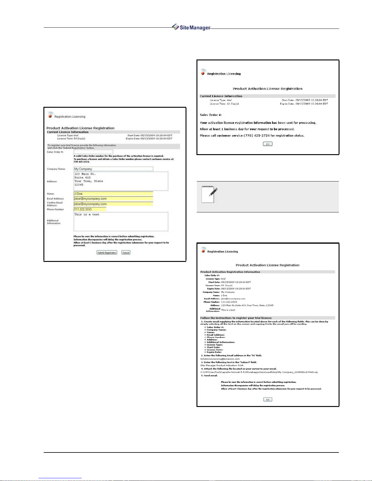
Company Name, Address, Name, E-mail, Con-
firm E-mail, and a contact Phone Number. If de-
sired, enter any extra information into the
Addition al Information box (optional). Note that
for non-SMTP enabl e d sy stem s , yo u m us t s peci fy if
the Web application is a virtual machine by selecting Yes or No for Virtual Server. Verify that the in-
formation you entered is correct and click the
Submit Registration button.
6. Click OK and you will return to the Feature Licens-
ing page.
Figure 2-6 - Registration Confirmation Window
NOTE: If your system is SMTP-enabled, go to
the Activation section. (For more information
on SMTP enabling, contact Technical Support.)
Figure 2-5 - Product Activation License Registration
Information Page
Your information will automatically be sent to
Emerson Re tail Solutions. If su ccessful, a confirm ation window (Figure 2-6) will open to notify you that
your registration information has been sent.
7. For systems that are not SMTP-enabled, after filling
out your information, follow the instructions in the
Product Activation and Licensing window:
Feature Licensing and Registration IT Administrator Functions • 9
Figure 2-7 - Product Activ ation License Registration Page (for
SMTP-disabled systems)
• Step 1 - Create an e-mail and include all the information listed in this step.
• Step 2 - Enter SolutionsLicensing@emerson.com in your e-mail's To: field.
• Step 3 - In the Subject: field of your e-mail, enter Site Manager Product Activ ation License
SO# (followed by the Sales Order number obtained from customer service).
• Step 4 - Open your browser windo w and l ocate
the directory that contains the.zip file (verify
that it is the most current version if there are
more than one).
• Step 5 - Send the e-mail to SolutionsLicensing@emerson.com
8. Click OK and this will return you to the Feature Li-
censing page.
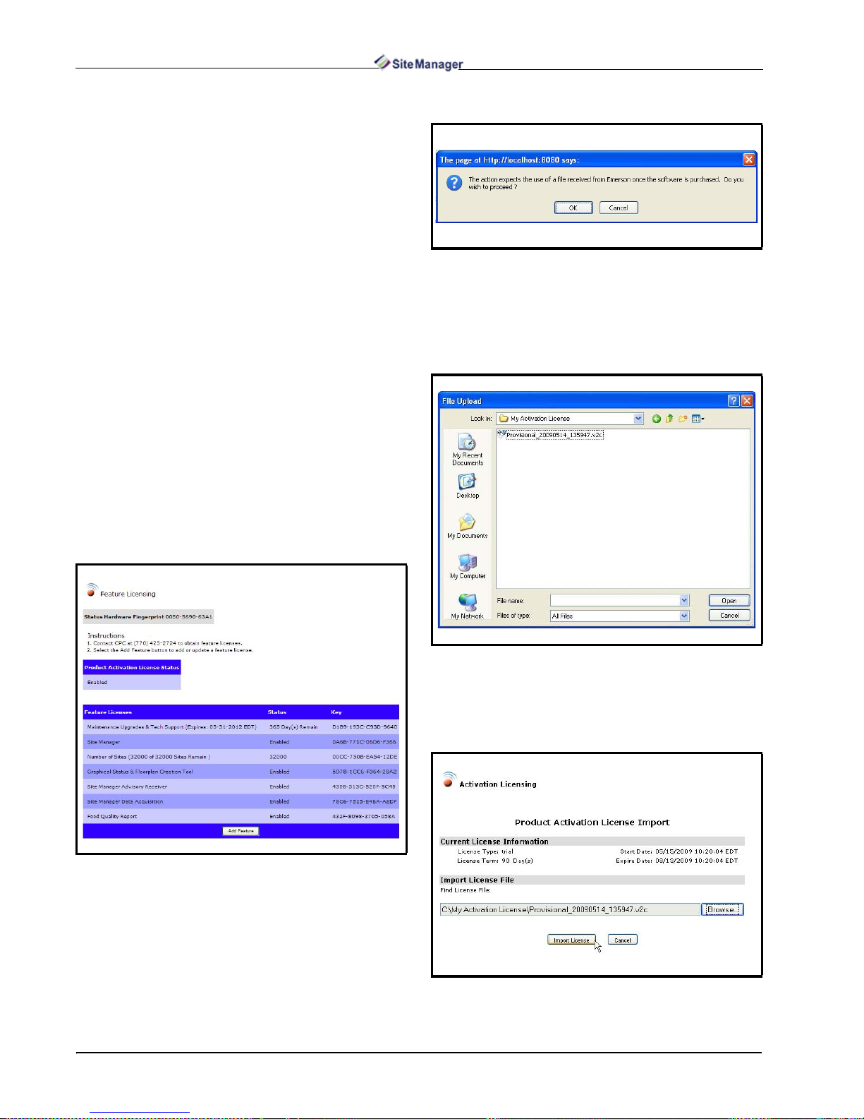
2.1.2. Activation
Once you receive the e-mail containing the file
that will activate your trial license, save the file to a
location on your drive.
2. Click OK on the confirmation window to proceed.
Figure 2-9 - Activat ion Window Prompt
The Product Activation License Import window
will open and show the current state of licensing.
3. Click Browse and the File Upload window will
open.
1. Go back to the Feature Licensing page and click
Activation:
Figure 2-8 - Feature Licensing Page
Figure 2-10 - File Upload Window
4. Highlight the file and click Open.
5. When the file appears in the Browse path, click the
Import License button:
10 • Site Manager User Manual 026-1012 Rev 3 06-DEC-2011
Figure 2-11 - Product Activation License Import Page

The Product Activation License Update window
will open (Figure 2-12).
Figure 2-12 - Product Activation License Update Page
6. Once the Apply Imported License button is
clicked, the selected license file will be applied (or
click Cancel to stop and exit).
Click the Add Feature button on the Feature Li-
censing page and enter t he ke y int o the boxes provided (Figure 2-13).
2.1.3. Licensing
Site Manager has bas ic (Maintenance Upgrades &
Tech Support license) and extra features that are acti-
vated by obtaining a licen se. The licens e key must be
entered on the Featur e Licens ing page to ac tivat e the
desired feature. A Maintenance Upgrades & Tech
Support license key activates basic features and the
feature license k ey activates f eature funct ionalitie s of
Site Manager.
The licensing activation page is accessible from
the Help drop-down menu. The menu will only be
visible with certain user privileges enabled to allow
you to add/edit software license keys.
Locate your unique Hardware Fingerprint num-
ber on the Feature Licensing page.
Call Retail Solutions Customer Service at 770-
425-2724 with the Hardware Fingerprint to obtain
a license key for the desir ed fea tures yo u wish to ac tivate.
Figure 2-13 - Feat ure Lice nsing Page
Click Save.
The key entered will know what feature it is associated with and will populate the appropriate field(s)
on the screen. To overr ide a n exis ting key , a ne w key
will need to be added and replace the existing key.
Click Cancel to stop and exit.
2.1.4. Maintenance Upgrades & Tech
Support Licensing
The basic features of Site Manager r equire a Maintenance Upgrades & Tech Support license key. Only
new users will need to enter thi s key. As the one-y ear
renewal period approaches, a reminder window will
appear and prompt you to r enew the Maintenance Up-
grades & Tech Support ke y. Conta ct Retail Solutions
Customer S ervice for renewal.
2.1.4.1. About Maintenance Upgrades &
Tech Support Licensing and Keys
Feature Licensing and Registration IT Administrator Functions • 11
Basic features require a Maintenance Upgrades &
Tech Support license key (that will need to be re-
newed yearly) and include feat ures su ch as us er info,
pending activities, activity history, setup, obtaining
controller info, adding, editing, and deleting d irectories, sites, and control syste ms, and some admin i strator functions.
For features such as backing up, sending reports,
forwarding and viewing advisori es, set poi nt broadcast, accessing the online help system, firmware
transfer, and more, a Site Manager license is needed
for activation. Additional plug-in features will need
specified keys for operation.
Contact Retail Solutions (770-425-2724) with
your Hardware Fingerprint information for acquir-
ing the license key. Con tact Te chn ical S upport for in structions on entering keys.
As the one-year renewal period approaches, a reminder window will appear to prompt you to renew
the Maintenance Upgrades & Tech Support license
key. Contact Retail Soluti ons Customer Servic e (770-
425-2724) for renewal.
2.1.4.2. About Feature Licensing and Keys
Licensed features require an activation key that
can be obtained through Retail Solutions Customer
Service. Contact Technical Support for instructions
on entering keys.
system\Screens\User
• If applicable:
webserverhome\webapps\emerson\WEBINF\classes\com\cpcus\jaru\ui\jsonrpc\GsFilesystem\Widgets\User
• webserverhome\webapps\emerson\WEBINF\classes\com\cpcus\jaru\ui\jsonrpc\GsFilesystem\Images
• Log retrieval schedule files located in:
webserverhome\webapps\emerson
If using a clustered environment, include these
steps when backing up:
STEP B
If the environment bei ng upgraded is now goi ng to
be in a clustere d environment, each worker box in the
cluster must have the GsFilesystem mirrored.
Copy the whole {tomcat webapp | worker classes
folder}\classes\com\cpcus\jaru\ui\jsonrpc\GsFile-
system folder identically to each worker box.
All possible Site Manager features will be dis-
played on the Site Manager Feature Activation
screen. To enable or update a feature, click the Add
Feature button.
The key entered will know what feature it is associated with and will popul ate t he approp ri ate fi eld on
the screen. To override an existing key, a new key
must be added and replace the existing key. Click
Save or Cancel to exit.
2.2. Database Backup
It is highly recommended that a backup of the database and Web server area s be perf ormed on a daily
basis for a complete recovery of information in the
event of a fa ilure of the Web server on which Site
Manager is running. It is suggested that user-created
components such as GS screens, widget s, images, and
schedules be backed up.
1. Back up the database using the standard procedure
for your particular database.
2. Back up the applicable Web server areas:
• webserverhome\webapps\emerson\WEBINF\classes\com\cpcus\jaru\ui\jsonrpc\GsFile-
NOTE: The location of these files are the default settings. They are user-c on figu r abl e and
therefore may be different. webserverhome is
the location of your particular Web server. For
example, a Web server location might be: c:\program
files\tomcat.
2.3. Importing XML Datafile
When exporti ng a tree from Ultrasite, the XML
file can either be exported from UltraSite or the Site
Manager PC applicat ion. For Ultr aSite , t he XML file
can be exported and sa ved via the Export Data opt ions
by right-clickin g on the UltraSite tree . The file will be
located in the UltraSite install location.
For the Site Manager PC application, the XML file
is stored in the Site Manager PC application install location, or a common location depending on the installation opti ons chosen at the time of the install. Note
that for the Site Manager PC application, all sites to be
imported are assumed to be E2 sites and must be
changed in the Site Manager application after importing is complete.
From the Start menu on the Web server machine,
go to Programs > Computer Process Controls >
Emerson > XML Import Directions and follow the
12 • Site Manager User Manual 026-1012 Rev 3 06-DEC-2011
instructions for importing the XML file. (The XML
import tool can be run as many times as desired and
will only import new sites and directories. To run it
more than once or to run it outside o f this in stallation,
view the XML import directions found at the path li sted above.)
NOTE: Since the Site Manager software must
have time to start, the Yes button may have to
be clicked several times after the Web server
has been started.
NOTE: Only sites not already in the database
will be imported, so the total number of sites
may be lower than expected.
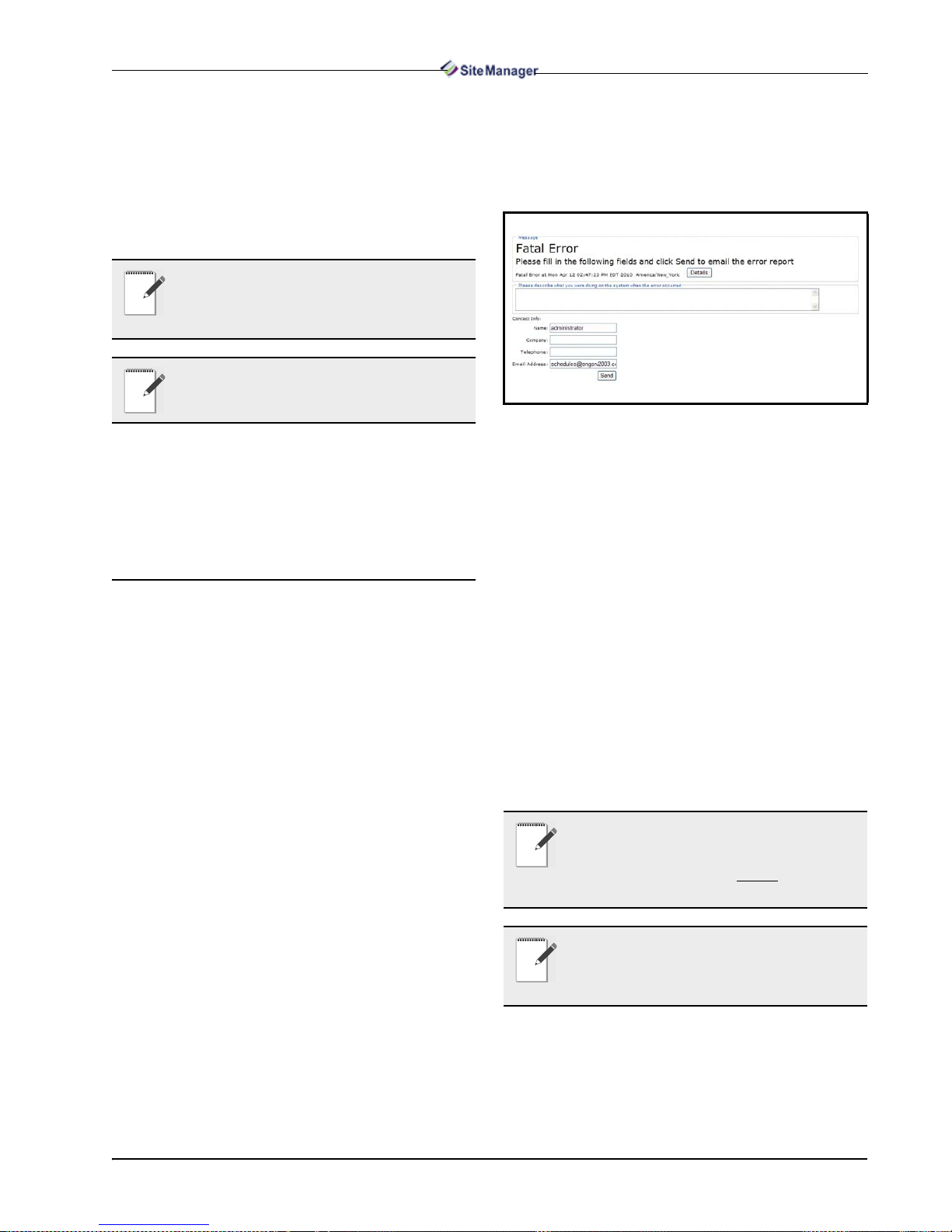
2.4.2. Error Report
If Site Manager encount ers a program malfuncti on
during a user’s bro wsing session, an erro r r epor t wil l
appear on screen:
Figure 2-14 - Fatal Error Page
2.3.1. Default Time Zone During
Import
If a time zone ID for a site is not present in the
XML import file, it will be set to US/Eastern as default.
2.4. Troubleshooting
2.4.1. Page Troubleshooting
2.4.1.1. Online Help Navigation - Pop-up
Window Scrolling in Online Help
To scroll through pop-up windows in the online
help, use the scroll wheel on your mouse. To close
pop-up windows, click anywhere off the pop-up. If
pop-up pages in the help appear blank, right-click inside the window and select Refresh.
The error report page displays information of
when (date and time) and where the error occurred.
The Details button will show a set of program
codes of the error when cl icked. Click Hide Details to
hide.
• Description - enter a description of the error in the
field provided (what you w ere doing before the error
took place, etc.)
• Company - enter the name of your company
• Telephone - enter your contact numbers
• Email Address - (pre-filled by default) th e err or re-
port will be sent to this email address
Required Fields: Description, Company, Tele-
phone
Click Send to send the error report email.
NOTE: The Help link that is found in this page
will not contain information about the current
page. When clicked, help information about
the page you were on right before
curred will display.
the error oc-
Troubleshooting IT Administrator Functions • 13
NOTE: IE 7 and above and the latest ve rsion of
Firefox (off the Firefox Web site) are the supported browsers. (IE 6 is suppo rted for viewing
GS screens only. )
3Menus
3.1. My Info Menu
3.1.1. About User Info
The My Info drop-down menu contains a list of
features that consists of anything th at pertain s to “personal items”, your user info, pe nding ac tivi ties , activ ity history, and when applicabl e, s avi ng a GS Scr een
as your system home page.
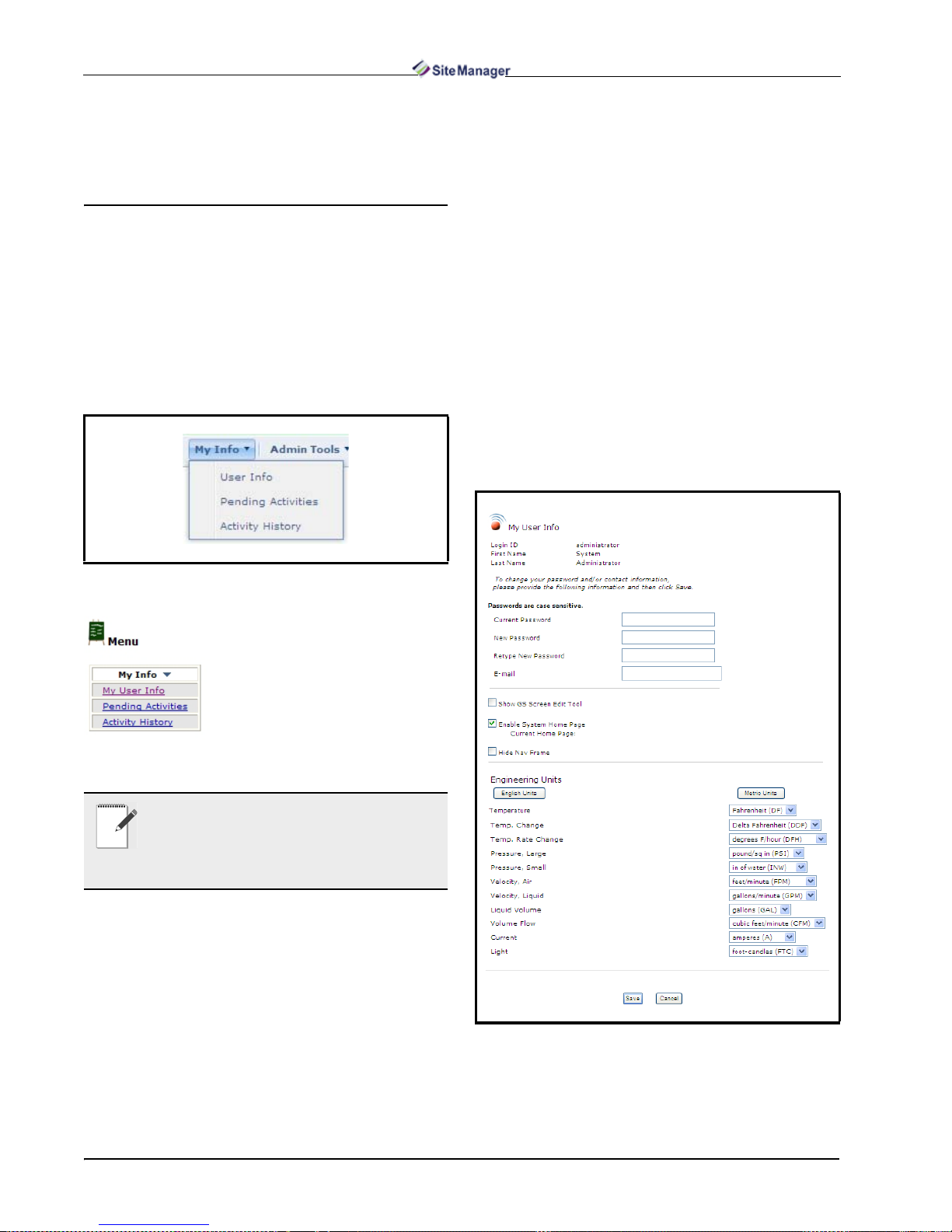
abled, the GS menus will become visible on the
right-click Navigation Tree m enu. Click the Save
button at the bottom of this page and refresh the
Navigation Tree for changes to take effect.
•If the Enable System Home Page checkbox is en-
abled, it will set the GS screen you choose as your
system home page (as indicated by Current Ho me
Page) on start-up.
•If the Hide Nav Frame checkbox is enabled, the
navigation tree will be hidden each time you log in.
The selected Home page can now be viewed on a
full screen.
Engineering units can be set to English or Metric
depending on the unit of measure the user requires.
Press the English Units button to se t all fields t o English and the Metric Units button to set all fields to
Metric. User Info is found under the My Info menu
bar. Click Save to store t he settings and exit the screen
or Cancel to cancel ch anges and exit the s creen.
Figure 3-1 - My Info (Expanded view shown)
From the My Info drop-down
list, you can view all of your
pending activities and your activity history.
If My Info is clicked, a menu appears with active links to each
function (figure on the left).
NOTE: If the user has Pending Activities with
a status that needs to be viewed, this page will
be the first page in the Site Manager main window that the user sees upon entering Site Man-
ager.
3.1.2. User Info
The User Info page allows you to view your current information, enable and disable Home p ages, and
change your password and contact information.
Login ID and Password information ca n be found
in the first section.
Figure 3-2 - My User Info Page
Checkbox Section:
•If the Show GS Screen Edit Tool checkbox is en-
14 • Site Manager User Manual 026-1012 Rev 3 06-DEC-2011
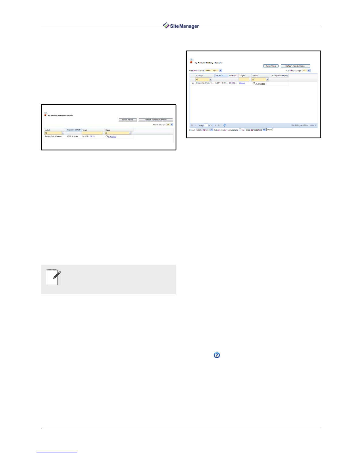
3.1.3. My Pending Activities
The My Pending Activities - Results page shows
the activities tha t you, th e curr en t u ser has bee n wait ing to start or that are in progress, and also shows activity status.
My Pending Activities is foun d under My Inf o on
the menu bar.
Figure 3-4 - My Activity History - Results Page
Figure 3-3 - My Pending Activities - Results Page
• Activity: An activity that is scheduled to start or cur-
rently being performed.
• Requested to Start: The start date and time the ac-
tivity was requested to start.
• Target: Reference to exactly where the activity is
taking place.
• Status: The status including items currently “in
progress” and items “waiting to start”. Each item’s
Status will be a link to the expanded information
page or status page if applicable. Only items that are
“In Progress” and “Waiting to Start” will be displayed.
NOTE: If the user has pending activities with
a status that needs to be viewed, the Pending
Activities page will be the first page the user
sees when first logging into Site Manager.
3.1.4. My Activity History
The My Activity History - Results page open s after
clicking Activi ty History under My Inf o on the menu
bar, or from the Navigation Tree menu.
Activity History - Resu lts at t he us er l evel s hows a
complete history of activities performed, including
such information as the type of activity that was performed, start and fin ish times, duration of the activity,
and more.
• Plus Sign (+) - Click the plus sign in the first column
to expand each activity and list any “child” activities, if there are any. If there are no “child” activities,
a message appears: No activities to display. For example, if logs are retrieved from the Unit level, the
plus sign, when selected, will expand and the user
can view each application type that had logs retrieved and the status. Therefore, if an activity failed
or is partially complete, users can select the plus
sign to see where the failure occurred.
• Activity - which activity was performed. (Clicking
Activity will sort everything alphabetically.)
• Started - the time and date the activity began.
(Clicking Started will sort everything in ascending
order.)
• Duration - total elapsed time for the activity to complete.
• User - the user who started the activity.
• Target - the node from where the activity was started. (Clicking a link in the Target column will open
the Properties page for that target.)
• Result - details the outcome of the activity and
whether or not it was successfully completed.
(Clicking a link in the Result column will open a
page containing more details about the activity performed.)
• Exceptions Report - click the Exceptions Report
icon from this column to open the Activity
Failed Report window, which displa ys a detailed information about the activity that was either failed or
partially completed.
My Info Menu Menus • 15

Click the down arrow that appears next to a column header to show more columns or enable sorting
options:
Figure 3-5 - My Activity History -Results Show More Columns
• Sort Ascending/Sort Descending - arranges the ac-
tivities alphabetically (from A-Z or Z-A).
• Activity ID - (internal use) internal key to the activ-
ity the user is currently on.
• Activity Parent ID - (internal use) internal key to
the parent activity of the one the user is currently on.
You can also choose to export all details of the ac-
tivities by clicking the checkbox. Click the Export
button to begin the download.
Figure 3-6 - My Activity History -Results Export Options
On the File Download window, click Open or
Save to continue with the download.
NOTE: Only the columns currently shown on
the page will be exported during file download.
Enable or disable column headers to show or
hide them during download.
NOTE: The activity history that you perfor m
can be specific to a directory, unit, or site. For
example, if the user right-clicked on a directory, site, unit, or control system in the naviga-
tion tree, results will be shown for the item selected.
Click Refresh Activity History and new additions will be displayed, if any.
Click Reset Filters to remove all filter s and refresh the activity history results.
Click the Next and Back links to scroll through
multiple results pages.
Sort the table to show historical activities that occurred from Today, Yesterday, Past 7 Days, or Last
Month by setting the Occurrence Date drop-down.
You can also set a custom date range (Custom
Range) to show data that occurred only within the
date you specified.
Export options are available at the bottom of the
page. This allows you to export current page information into different output formats such as Excel
Spreadsheet, HTML, and PDF. Select the format
from the Export drop-down and select whether to ex port All activities displayed or only those Not Com-
pleted (“Failed” and “Partially Completed”
activities).
Figure 3-7 - Navigation Menu Active History
16 • Site Manager User Manual 026-1012 Rev 3 06-DEC-2011
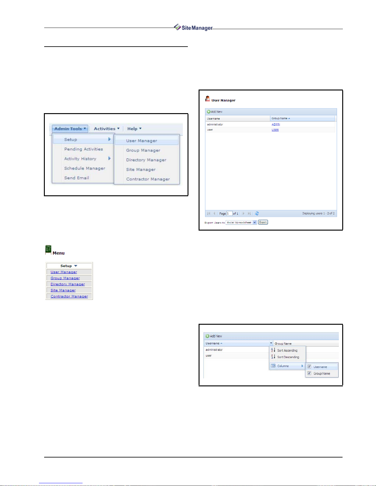
3.2.1.1. User Manager
3.2. Admin Tools Menu
3.2.1. Setup
Site Manager Setup is found under Admin Tools
on the menu bar. Figure 3-8 shows the menu when
expanded:
Figure 3-8 - Admin Tools Menu (Expanded view shown)
Setup contains the following choices for the administrator: User Manager, Group Manager, Directory Manager, Site Manager, and Contractor Manager.
The User Manager lists all users in the database.
From the User Manager page you c an select a user to
edit, delete a user, or jump to the User Configura tion
page to add a user.
Figure 3-9 - User Manager Page
Administrator level functionalities are executed from this menu,
such as administrator activity history searches, viewing administrator pending activities, and
assigning user levels and access
rights.
If Setup is clicked from the Ad-
min Tools menu, the menu ap-
pears on the main window with active links to each
function.
User names and group names that are currently
added in the database will display in this page.
If more users are in the database than can display
on a single page, th e list of us er names wil l appear on
multiple pages as indicated at the bottom of the window (Page 1 of 1).
Click the Username header for a quick sort or
click the dr op-down arrow to open the sort menu:
Figure 3-10 - Username List Sorting
To download current user information, select from
the available export formats from the Export drop-
down at the bottom of the page: Excel Spreadsheet,
HTML, and PDF.
Admin Tools Menu Menus • 17
Click Open or Save on the File Downlo ad win-
dow to proceed with the download.
Adding a New User
To add a user, cli ck the Add New button from the
User Manager page and enter the infor mation into the
fields on the User Configuration page, refer to Figure
3-11.
Editing a User
To edit a us er, view the list of all users from the
User Manager page and select t he desired user name.
Click Edit and the User Configurati on page (se e Fig-
ure 3-11) will open where you can enter changes.
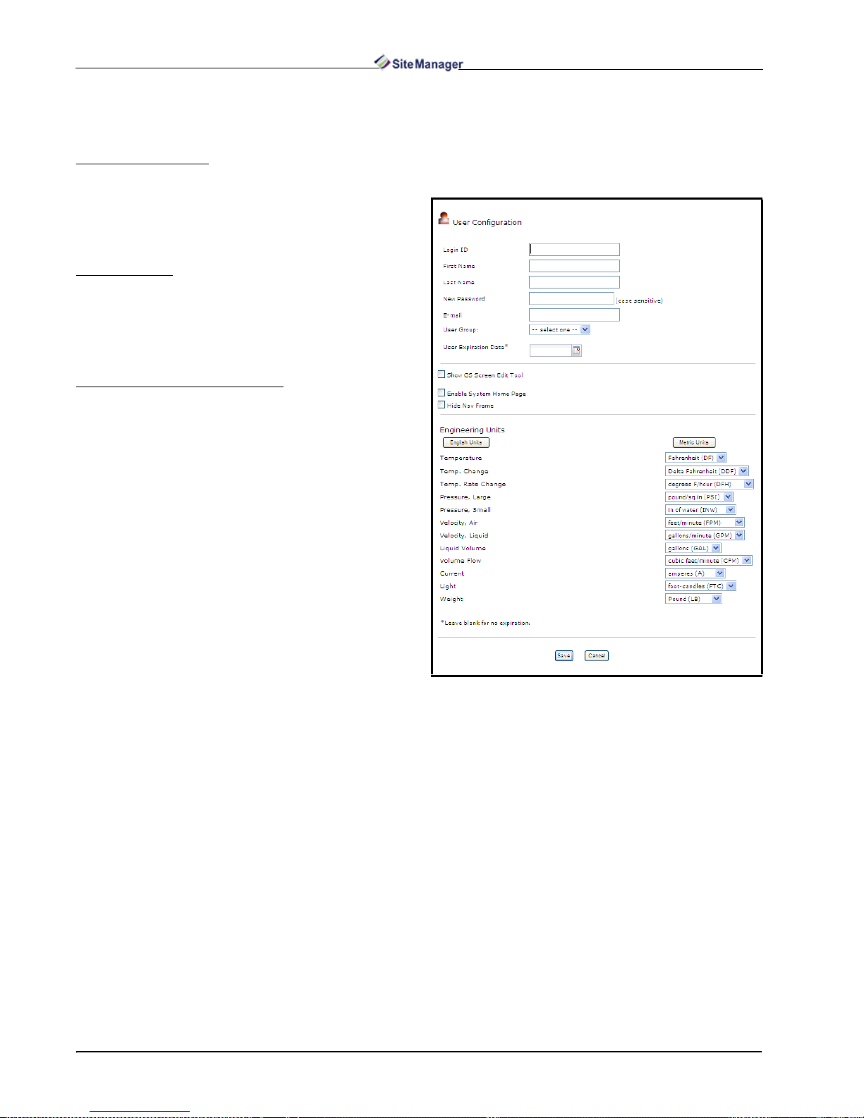
Configuring User Information
Add and Edit users from the User Configuration
page. Enter Login ID, Name, e-mail address, user
group, and time zone info rmation. Use the calendar to
set the user expiration dat e (leave blank for no expiration). Click Save to store changes or Cancel to exit
without saving and retur n to th e User Mana ger pag e.
Assign user leve ls and acce ss rights to those l evels by
using the Group Manager.
Changing User Passwords: Reset user pass-
words by enabling the Change Password checkbox
and entering the ne w pa ssword. Retype the new pa ss word again and enter a password hi nt for password recovery. Click Save.
Checkbox Section:
•If the Show GS Screen Edit Tool checkbox is en-
abled, the GS menus will become visible on the
right-clic k Navigation Tree menu. Click the Save
button at the bottom of this page and refresh the
Navigation Tree for changes to take effect.
•If the Enable System Home Page checkb ox is en-
abled, it will set the GS screen you choose as your
system home page (as indicated by Current Home
Page) on start-up.
•If the Hide Nav Fram e checkbox is enabled, the
navigation tree will be hidden each time you log in.
The selected Home page can now be viewed on a
full screen.
Engineering units can be set to English or Metric
depending on the unit of measure the user requires.
Press the English Units b utton to se t all fields t o English and the Metric Units button to set all fields to
Metric. Click Save to store the settings and exit the
screen or Cancel to cancel changes and exit the
screen.
Figure 3-11 - User Configuration Page
Required fields: Login ID, First Name, Last
Name, Password, User Group.
18 • Site Manager User Manual 026-1012 Rev 3 06-DEC-2011
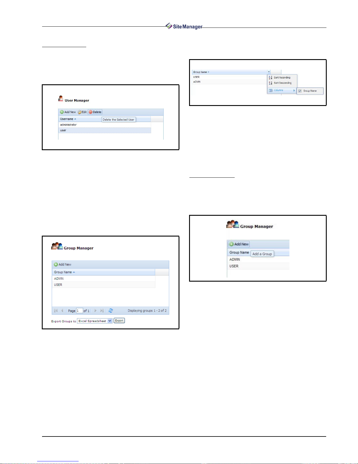
Deleting a User
Delete a user by selecti ng the userna me (Adminis -
trator excluded) and clicking Delete. A confirmation
window will open asking if you are sure you want to
delete the user.
Click the Group Name heade r f or a qui ck sort or
click the dr op-down arrow to open the sort menu:
Figure 3-14 - Group Name List Sorting
To export group data, select f rom the availa ble ex-
port formats from the drop-down below the table: Ex-
cel Spreadsheet, HTML, and PDF.
Figure 3-12 - User Configuration Page - Delete User
3.2.1.2. Group Manager
Configure user levels and assign access rights to
those levels by using the Gro up Manager. The Group
Manager lists all group names in the database. Each
group is a link t hat allows a user to edit that group pro file. Select the group name to see Edit and Delete options. If ADMIN is selected, the Delete option
disappears.
Click Open or Save on the Fil e Download win-
dow to proceed with the download.
Adding a Group
To add a new group, click Add New from the
Group Manager page (Figure 3-15) and enter the in-
formation into the f ields on the Group Configur ation
page.
Figure 3-15 - Add New Group
Figure 3-13 - Group Manager Page
Group names that ar e currently in the data base will
display in the page . If more groups are in the database
than can display on a single page, the list of group
names will appear on multiple pages as indicated at
the bottom of the window (Page 1 of 1).
Admin Tools Menu Menus • 19
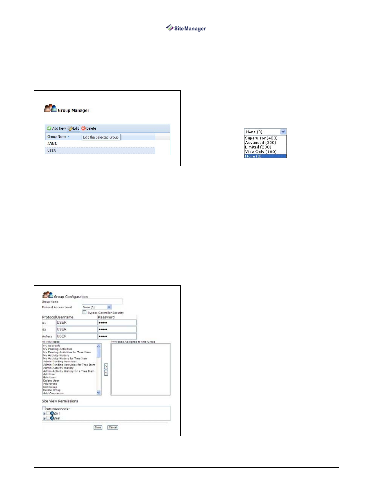
Editing a Group
View the list of all gro ups from the Gro up Manag-
er page (Figure 3-16) and select the desired group
name. Click Edit and the Group Configuration page
will open where you can enter changes.
Figure 3-16 - Edit Group
Configuring Group Information
Add or edit a new group fr om the Group Conf igu -
ration page and set up user privileges. All privileges
can be added or subtract ed to a user at th e admin level
on this page. To add or subtract pri vi le ges for a us er,
highlight the privi lege in the left column and click t he
left and rig ht arrows. The right arrow on the top will
assign privileges, the left or bottom arrow will unassign the privilege. Click the Save button to save and
the Cancel button to return to the Group Manager
page. Mouse over each pr ivi lege to see its def in it io n.
Name the new Group by entering it into the Group
Name field, then selec t t he d esi red access level from
the Protocol Access Level drop-down list. These levels are dependent on privileges that have been set in
the controller, and determine what actions the user
can perform.
Protocol Access Level : Assi gn an acces s level to
the group by using the drop-down menu:
• Supervisor: no restrictions on user privileges -ad-
ministrator level
• Advanced: has all access except administrator- level
rights
• Limited: user has the basic level of user privileges.
Can edit and add basic parameters.
• View only: user has no ability to edit or add infor-
mation
• None: no privileges have been assigned to user
Bypassing controller security: The Bypa ss Controller Securit y opti on ca n all ow a us er t o log in and
perform actions to the controller regardless of the
what security settin gs have been set in that contro ller.
When checked, the Bypass Controller Security
checkbox will bypass an y security settings inside the
controller and use only the protocol sett ings set in the
Protocol, Username, Password table.
Figure 3-17 - Group Config uration Page
20 • Site Manager User Manual 026-1012 Rev 3 06-DEC-2011
Security set tings for Site Manager d efault at the
group configuration level normally. Under the Op-
tional section: If this protocol checkbox is enabled
here (at the control system level), Site Manager will
use the protocol information entered at the control
system level and bypass the i n fo rmat ion at the group
level for only the uni ts loca ted under this control sys tem.
All Privileges: Use the arrows to select which
privileges will be ass igned to the Group ( the pri vileg es that are assig ned will be gra yed o ut so th ey canno t
be assigned twice) . A pr iv il ege is an activity t hat can
be performed in Site Manager.

Click Save t o save the new Gro up and its pri vileg-
es and go back to the Group Manager page. Click
Cancel to exit without saving and go back to the
Group Manager page.
Required fields: Group Name and at least one
privilege.
Site View Permissions: You can assign permis-
sions (which directories and sites) to each Group by
enabling the checkboxes next to them.
NOTE: If you have added or deleted directories
and sites to the databa se at the Navigation Tree
level after
checkboxes will not be selected automatically.
Simply enable these descendants’ checkboxes manually.
these selections have been made, the
Deleting a Group
A group (Administrator excluded) can be deleted
by selecting the desi red group and cl icking Delete. A
confirmation window wil l open asking if you are sure
you want to delete the gr oup. Cli ck OK to delete, No
to stop.
Click the Directory h eader for a quick sort or click
the drop-down arrow to open the sort menu:
Figure 3-19 - Directory List Sorting
Adding a Directory
To add a new dire ctory, cli ck the Add New button
from the Directory Manager page (Figure 3-20) and
enter the information into the fields on the Directory
Configuration page.
3.2.1.3. Directory Manager
The Directory Manager lists all directories in the
database. From the Directory Man ager page you ca n
select a directory to edit, delete a directory, view its
properties, or jump to the Directory Configuration
page to add a directory.
Figure 3-18 - Directory Manager Page
If more directories are in the database than can display on a single pag e, t he list of direct ory na me s wi ll
appear on multiple pages as indicated at the bottom of
the window (Page 1 of 1).
Figure 3-20 - Add New Directory
Editing a Directory
View the list of all directories from the Directory
Manager page (Figure 3-21) and select the desired
directory name you wish to edit.
Click Edit to open the Directory Configuration
page where you can enter changes.
Figure 3-21 - Edit Directory
Admin Tools Menu Menus • 21
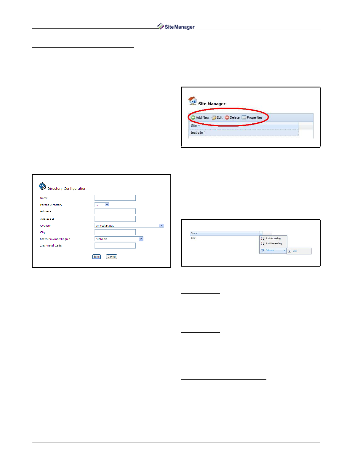
Configuring Directory Information
Add or edit a new directory from the Directory
Configuration page. Ed it the directory i nformation by
changing the current information in the fields, or by
entering new information for a new directory in the
fields. If United States is selected as the country, a
drop-down menu with all the states will be shown. If
another country is selected, the State/Province/Re-
gion d rop-down menu will be ch anged to a blank text
field to allow a name to be entered in the field. Click
Save to store changes and Cancel to exit without saving and return to the Directory Manager page.
The Directory Configuration page is also avail-
able from the ri ght-c li ck/mouse -over Add Direc tory
and Edit Directory menus at the Directory level in
the Site Manager navigation tree.
3.2.1.4. Site Manager
The Site Manager lists all sites in the database.
From the Site Manager page you can select a site to
edit, delete a site, view its properties, or jump to the
Site Configuration page to add a site.
Figure 3-23 - Site Manager Page
If more sites are in the database than can display
on a single page, the li st of site names will appe ar on
multiple pages as indicated at the bottom of the window (Page 1 of 1).
Click the Site header for a quick sort or click the
drop-down arrow to open the sort menu:
Figure 3-22 - Directory Config uration Page
Required field: Name.
Deleting a Directory
A user can delete a directory by selecting the di-
rectory from the lis t and cl icki ng Delete. A confirmation window will open and ask if you are sure you
want to delete the directory.
Click OK to delete, No to stop.
Figure 3-24 - Sort Site Names
Adding a Site
To add a new site, click Add New from the Site
Manager page and enter the information into the
fields on the Site Configuration page.
Editing a Site
To edit a site, view the list of all sites from the Site
Manager page and select the desi red sit e name. Click
Edit and the Sit e Configuration page will open where
the user wi ll enter changes.
Configuring Site Information
Add or edit a new site from the Site Con figuration
page. Edit the site information by changing the current information in the fields, or entering new information for a new site in the fields. If the United
States is selected as the country, a drop-down menu
22 • Site Manager User Manual 026-1012 Rev 3 06-DEC-2011

with all the states will be shown. If another coun try is
selected, the State/Province/Region drop-down
menu will be changed to a blank text field to allow a
name to be entered in the fi eld. Click t he Save butt on
to save and the Cancel button to return to the Site
Manager page.
The Site Configuration page is also available from
the right-c lick/mouse-over Add Site and Edit Site
menus at the Directory or Site levels in the navigation
tree. Click Save to store changes or Cancel to exit
without saving and return to the Site Manager page.
Erase contractor inf ormation from the datab ase by
selecting a contractor from the list and clicking De-
lete.
Edit contractor infor mation by selecti ng a contrac-
tor name and clicking Edit. This will take you to the
Contractor Configuration page where contractor information can be edited.
View contact details about each contractor by se-
lecting a contractor name and clicking Properties.
This will take you to the Contractor Properties page
that will show details about the selected contractor.
Figure 3-25 - Site Configuration Page
Required fields: Name and Time Zone.
Control Systems can be added and deleted from
this page. Click the Add Contro l Syst em button to
add a new control system.
Deleting a Site
A user can delete a si te by selecting the desired site
and clicking Delete. A confirmation window will
open and ask if you are sure you want to delete the
site.
Click OK to delete, No to stop.
3.2.1.5. Contractor Manager
To manage contractor information, go to the Con-
tractor Manager page under Admin Tools.
Add a new contracto r by c li cki ng Add New . This
will take you to the Contractor Configuration page
where all information about the contractor can be entered.
Figure 3-26 - Contract or Manager Page
Click the Contractor Name header for a quick
sort or click the drop-down arrow to open the sort
menu:
Figure 3-27 - Sort Contractor Name
Configuring Contractor Information
Add or edit a new contr act or fr om th e Contractor
Configuration page. Edit th e contractor information
by changing the current information in the fields, or
by entering new information for a new contractor in
the fields. If United States is selected as the country,
a drop-down menu with all the states will be shown.
If another country is select ed, the State/Province/Re-
gion dr op-down menu will be ch anged to a blank t ext
Admin Tools Menu Menus • 23

field to allow a name to be entered in the field. Click
Save to store changes and Cancel to exit without saving and return to the Contractor Manager page.
Figure 3-28 - Contractor Configuration Page
Required fields: E-mail.
Contractor Properties
From this page you can view detai led informati on
about the contractor, delete a contractor (a pop-up
window will appear and ask if you are sure), a nd edit
a contractor (this will take yo u to the Cont ractor Con-
figuration page). Click ing the Contractor Properties
link refreshes this page.
3.2.2. Pending Activities
The Pending Activities - Results page shows the
current activities that users have waiting to start or
that are in progress, and also shows activity status.
Pending Activities is found under the Admin Tools
menu on the menu bar.
Figure 3-30 - Pending Activi ties - Results page (Admin level
view shown)
• Activity: An activity that is scheduled to start or cur-
rently being performed.
• Requested to Start (Site Time): The default time is
displayed depending on the page that the user is
viewing.
• User: The user to which the pending activity is as-
signed.
• Target: Reference to exactly where the activity is
taking place.
• Status: The status including items currently “in
progress” and “waiting to start”. Each item’s Status
will be a link to the expanded information page or
status page if applicable. Only items that are “In
Progress” and “Waiting to Start” will be displayed.
Figure 3-29 - Contractor P roperties Page
24 • Site Manager User Manual 026-1012 Rev 3 06-DEC-2011
NOTE: If the user has pending activities wi th
a status that needs to be viewed, the Pending
Activities page will be the first page the user
sees when fir st logging in t o Site Manager.
3.2.3. Admin Activity History
3.2.3.1. View History
The Activity History - Results page opens after
clicking Activity History und er Admin Tools on the
menu bar, or from the Navigat ion Tree menu. Figure
3-31 shows an illustration of the page.

Activity History - Res ul ts at the admi nistr ator lev el shows a complete history of activities performed,
including such in formation as t he type of ac tivity th at
was performed, start and fini sh time s, duratio n of the
activity, user information, and more.
view by Result type.
• Exceptions Report - Click the Exceptions Report
icon from this column to open a window that displays details of the activity that was either failed or
partially completed.
• Sort Ascending/Sort Descending - arranges the ac-
tivities alphabetically (from A-Z or Z-A).
• Activity ID - (internal use) internal key to the activ-
ity the user is currently on.
• Activity Parent ID - (internal use) internal key to
the parent activity of the one the user is currently on.
Click Refresh Activity History and new addi-
tions will be displayed, if any.
Figure 3-31 - Activity History - Results page (Admin level view
shown)
• Plus Sign (+): Click the plus sign in the firs t colum n
to expand each activity and list any “child” activities, if there are any. If there are no “child” activities,
a message appears: No activities to display. For example, if logs are retrieved from the Unit level, the
plus sign, when selected, will expand and the user
can view each application type that had logs retrieved and the status. Therefore, if an activity failed
or is partially complete, users can select the plus
sign to see where the failure occurred.
• Activity: Which activity was performed. (Clicking
Activity will sort everything alphabetically.) Use
the drop-down menu to view all of a certain type of
activity.
• Started: The time and date the activity began.
(Clicking Started will sort everything in ascending
order.) Use the Occurrence Date drop-down to
view a specific time frame: All, Today, Yesterday,
and Past 7 Days, Last Month, or Custom Range
(enter your desired date range).
• Duration: The elapsed time of the activity.
• User: The user who performed the activity. (Clicking User will sort by user name in alphabetical order.)
• Target: Shows on what property the activity was
performed. (Clicking a link in the Target column
will open the Properties page for that target.)
• Result: Details the outcome of the activity and
whether or not it was successfully completed.
(Clicking a link in the Result column will open an
Activity Details box containing more details about
the activity performed.) Use the drop-down menu to
Click Reset Filters to remove all filters and re-
fresh the ac tivity history results.
Click the Next and Back links to scroll through
multiple results pages.
Sort the table to show historical activities that oc-
curred from Today, Yesterday, Past 7 Days, or Last
Month by setting the Occurrence Date drop-down.
You can also set a custom date range (Custom
Range) to show data that occurred only within the
date you specified.
Export options are available at the bottom of the
page. This allows you t o export current page inf ormation into different output formats such as Excel
Spreadsheet, HTML, and PDF. Select the format
from the Export drop-down and select whether to export All activities displayed or only those Not Com-
pleted (“Failed” and “Partially Completed”
activities). Yo u can also choose to export all details of
the activities by clicking the checkbox. Click the Ex-
port button to begin the download.
NOTE: Only the columns currently shown on
the page will be exported during file download.
Enable or disable column headers to show or
hide them during download.
NOTE: The activities history you perform can
be specific to a directory, unit, or site. For example, if the user right-clicked on a directory,
site, unit, or control system in the Navigation
Tree, results will be shown for the item selected.
Admin Tools Menu Menus • 25

Figure 3-32 - Admin Activity History Menu from Navigation Tree
3.2.3.2. Configure Purge
Activity History data is st ore d in the database but
can be deleted with t he Configu re Purge f eature. You
can choose to keep the default setting of never purging (keep all records forever), or choose to keep only
a specific number of weeks or months by con figuring
the parameter settings.
Enter the number of weeks/months and time of
day to remove old items depending on which you
choose.
Click Save to save the settings, Cancel to stop and
exit.
To access the Schedule Manager page, click
Schedule Manager from the Admin Tools menu.
The page will show a table that lists all the scheduled
activities based on server’s time zone.
Figure 3-34 - Schedule Manager Page
3.2.4.1. Setting Up User Schedules
There are two categories of schedules: user and
system. User schedules are created and edited by us-
ers. System schedules ar e automatically set up and are
not able to be edited by users. A table with all the
scheduled activities will be displayed.
By default, the colu mns are sorted accordi ng to the
next run time, which will be in ascending order. The
columns are sorted by clic king on the column he ader.
Figure 3-33 - Configure Purge Page
3.2.4. Schedule Manager
Activities can be scheduled so you can manage
when and how often they are run. All schedules are
based on the server’s time zone. The server’s time
zone will be displayed to the user at the top of the
screen under the Schedule Manager heading. All
schedules are based on the server time zone.
• Name: A unique descriptive nam e giv e n to a s c hed -
ule by the user or Site Manager in case of a system
scheduled activity.
• Type: The type of activity scheduled. If it is a sys-
tem scheduled activity, then the Type will be system. If user, the Type will be user. You can select the
type of filter from within the Type column.
• User: The user who created or last modified the
schedule. This user is the “owner” of the schedule.
The user column will not be visible if the user has
only Edit My Scheduled Activities and/or Delete My
Scheduled Activities privileges.
• Schedule: A description of when the schedule will
run.
• Next Run Time: A time stamp of when the next
date/time the schedule will run.
• Last Run Time: A time stamp of when the last date/
time the schedule ran. If the schedu le has not run yet,
Last Run Time will be left blank.
• Status: The last status of the schedule will be dis-
played. Icons will be displayed similar to the icons
26 • Site Manager User Manual 026-1012 Rev 3 06-DEC-2011

used in Activity History.
The status may be clicked on to view the detailed activity history for that schedule.
The status will be linked to the most recent activity
history that is attached to the schedule and has not
been purged.
If the schedule has not run yet, Last Status will be
left blank.
The buttons place d a t t he top of the table ar e used
for adding, editing, deletin g, and disabling schedules .
The buttons underneath are for scrolling and refreshing the page.
Figure 3-35 - Schedule Manager Header Buttons
• Add New: The Schedule Manager screen will open
once the user clicks Add New. This will open the
screen that allow users to create a new user scheduled activity and configure.
• Edit: Clicking on the Edit button will allow users to
go into the schedule screen to modify or view the details of the schedule.
• Delete: Only user schedules may be deleted. You
will be prompted to confirm or cancel.
•Disable/Enable: Depending on Edit privilege given
to your group, you can disable or enable schedules
anytime from this page by clicking the Disable/En-
able toggle button. Disabling a schedule will not delete it in the list but will only suspend it until the time
you (or another user) set it back to “Enable” mode.
• Run Now: If you would like to run an existing
schedule immediately, click on the Run Now button. Once selected, the progress page opens.
• Reset Filters: Applied filters will reset to default.
The graphic below shows an example of a Backup
activity to be scheduled on a daily basis (Calendar
Based):
Figure 3-36 - Example of a Scheduled Activity (Calendar Based)
A schedule can be set to run once. If Run Once is
chosen, options for Interval and Calendar Based will
not be shown.
NOTE: Setpoint Broadcasts may only be configured on a Run Once or Calendar-based
schedule.
Notification can be sent concerning the status of
the schedule based on two options:
• On Success: Activity was successful.
• On Unsuccessful: Activity was unsuccessful,
which means partially completed or failed.
Adding a new or modifying an existing
schedule
Double-clicking on a sche dul e wil l all ow use rs to
edit that schedule (same as clicking the Edit button).
Admin Tools Menu Menus • 27
To run a schedule daily, enter a Date and specify
the time the schedule should run. Leave the End
Date/Time blank to keep running indefinitely. A validation pro mpt will occur if the correct time was no t
entered.

Schedules can al so be based on an int er val (select
the Interval Based option):
3.2.4.2. User Schedules
Scheduling Setpoint Broadcast
When store hours change or special event s occ u r,
scheduling a Setp oint Broadcas t can send da ta to multiple group s, sites, and/or multiple controllers at one
site, and provides the ability to send setpoint and parameter information across a single enterprise.
To schedule Setpoint Broadcast, refer to Section
3.3.2., Setpoint Broadcast.
Figure 3-37 - Example of a Scheduled Activity (Interval Ba se d )
Enter the Number of times to repeat or leave
blank to run indefinitely.
Note that there will be no opt ion for interva l based
schedules if Setpoint Broa dcast i s selec ted fr om the
Type drop-down menu.
Schedules can also be Calendar-based:
Figure 3-38 - Example of a Scheduled Activity (Calendar Based)
Scheduling Retrieve Logs
Retrieving logs shows a historical view of inputs
and outputs of the applications you choose retrieve
logs on, which creates a history of records of the inputs and outputs for that application.
For scheduling Log Retrievals, enter a name and
choose whether the l og retrieval sho uld be run now or
on a schedule. Select the type of Schedule (one-time
only, at intervals, or calendar-based).
• Months: Users will have the option to multi-select
any month/months f rom Janu ary to December. This
selection is only visib le for Days o f Week and Days
of Month calendar schedules.
• Days of the Week: Multi-select any day/days fro m
Sunday to Saturday. This selection is only visible for
Days of Week calendar schedules.
• Hours and Minutes:
Hours: multi-select any hour/hours from 0 to 23.
Minutes: multi-select any minute/minutes from 0 to
55 in 5 minute increments.
Or select the All button instead of manually clicking
on each option at the end of each selection.
Clear any selections by clicking on the Clear but-
ton.
28 • Site Manager User Manual 026-1012 Rev 3 06-DEC-2011
Figure 3-39 - Scheduling Retrieve Logs
Scheduling Retrieve Logs From List
One or more appropriate selection of lists can be
chosen when the Retrieve Logs From List is sele cted.
Only the points with logs tha t ar e i ncl uded in the previously made list will be retrieved.
Click Run Now > Go to run the activity immediately or save the schedule conf iguration to be run later
on a schedule (Run On Schedule).

Click the Power Builder link to open the List
Power Builder window.
For scheduling Refresh Point List, enter a name
and choose whether ref reshing the point list sh ould be
run now or on a schedule. Select the ty pe of Schedule
(one-time only, at intervals, or calendar-based ).
Figure 3-41 - Scheduling Refresh Point List
Scheduling Backup
Figure 3-40 - Scheduling Retrieve Logs From List
Scheduling Refresh Point List
Refresh point list is an activity that may be performed at a control sys tem level. When a refresh point
list is performed, information is pulled from the controller and is posted to the database.
A Backup saves information from a controller to
the server and can be done at the directory, site, control system, or unit level.
For scheduling a Backup, enter a name and choose
whether the backup should be run now or on a schedule. Select the type of Sched u le (one -t ime only, at intervals, or calendar-based).
Admin Tools Menu Menus • 29
Figure 3-42 - Schedu ling Backup

Scheduling Obtain Controller Information
The Obtain C ontroller Information activity connects to a given Control System, refreshes the Unit
list, refreshes the Application List for each Unit, and
refreshes the points for any Application Instances that
have “out of date” points, which means the point list
will be retrieved f or an y appl ications that have never
had a point list r etrieved, and also for any applicat ions
that have changed since the last time the point list information was checked. (Obtain Controller Infor mation can be scheduled from the Schedule Manager:
For more information on Firmware Update Trans-
fers, see Section 5.2., Fir mware Update Transfer.
Scheduling Firmware Update Apply
The third step to updating firmware is to apply the
firmware to the controller. Firmware Apply can be
configured for d eploymen t at the Con trol System l ev el only, from the Schedule Manager. The Firmware
Apply activity is design ed t o onl y Run Now wi tho ut
the option for sche duling fut ure time or dat e (no Run
on Schedule option). After setti ng the conf igura tion,
Click Go to run:
Figure 3-43 - Scheduling Obtain Controller Information
Scheduling Firmware Update Transfer
Use the Schedule Mana ger to upl oad the f irmware
update pack age to the server (firmw are transfer). Set
the Configuration and Firmware Transfer Selections:
Figure 3-44 - Scheduling Firmware Transfer
Figure 3-45 - Schedu ling Firmware Apply
For more information on Firmware Update Apply,
see Section 5.3., Firmware Update Apply.
Scheduling Upload Description File
A description file is a file used to add functional ity
into the E2 controller. To run this activity on a later
date, select Run On Schedule and configure it from
the Schedule Manager page.
NOTE: This Activity can be scheduled, but not
recurring.
See Section 4.6.9.1., Descri pt ion Fil e Upload to
the E2 Controller for mor e informatio n on uploadin g
description files.
3.2.4.3. Filtering Rules
Filtering R ules is a configurat ion of the Retrieve
Logs, Retrieve Logs From List, Setpoint Broadcast,
Refresh Point List, and Backup acti vities. Use the Fil-
30 • Site Manager User Manual 026-1012 Rev 3 06-DEC-2011

ter Rules List when retrieving logs for directories,
sites, control systems, or units . This will configure the
Retrieve Log activity by f iltering which logs you wish
to retrieve. Selec t the applic ations by ena bling the ap plication checkboxes and clicking Go.
If you wish Site Manager to retrieve logs automat-
ically at a specifi ed time for each da y, enable the Run
On Schedule option you will be directed to the
Schedule Manager page. Enable th e Run Now check box if you wish to retrieve logs now. Set up multiple
schedules for multiple days from the Schedule Manager. Click the Go button to run the activity and retrieve logs.
Logs can be retrieved hierarchically from the Di-
rectory level all the way to the Po int level.
To send an email from this page:
1. Select the format of your email from the Email For-
mat drop list (HTML or Text).
2. In the Users list, select your e-mail recipients by enabling the checkbox next to the name of the user.
(Names and e-mail addresses of users saved to the
database will display in this list.) If an email address
was not provided during user setup, a NO EMAIL
SET UP will display below the user name.
3. If your recipient is not in the list or the user email
address is not set up, enter the recipient’s email address in the Additional Email Addresses field.
Separate email addresses with a comma “,”.
4. Type your message in the Body field and provid e a
Subject for your email (required).
5. Click Send. A message will display if the email was
sent successfully. Click Cancel if you wish to cancel Send Email.
NOTE: SMTP has to be set up initially to enable this fea t ure.
Figure 3-46 - Filtering Rules
3.2.5. Send Email
This page allows yo u t o cr eate and send emails t o
users of Site Manager. To go to this page, click the
Admin Tools menu, then click Send Email. The
Send Email page opens (Figure 3-47).
NOTE: The Send Email is an Admi n group default privilege; lower level groups must be assigned of this privilege to access this page. For
assistance, contact your system administrator.
3.3. Activities Menu
3.3.1. Advisory Menus
3.3.1.1. Connection Verification Report
This report allows users to determine which sites
in the navigation tr ee are in good communication s ta tus and which sites are not (problem sites). To know
more about this advisory report, refer to Section
6.2.1., Connection Verification Report.
3.3.1.2. Purge Inbound Connections
Purge Inbound Connection allo ws you to set purge
configurations for inbound connection records. For
more information about this advisory configuration,
see Section 6.2.2., Purge Inbound Connections.
Figure 3-47 - Send Email Page
Activities Menu Menus • 31

3.3.1.3. Advisory Forwarding
With the Advisory Forwarding feature, advisories
can be forwarded to an email address. See Section
6.2.3., Advisory Forwarding for more information
about advisory forwarding.
3.3.2. Setpoint Broadcast
When store hours change or special event s occ ur ,
scheduling a Setp oint Broadcas t can send d ata to multiple groups, sites, and/or multiple controllers at one
site, and provides the ability to send setpoint and parameter information across a sin gle enterprise.
Based on the user’s privilege, all configured setpoint broadcasts will be displayed (if any). If there are
no existing setpoint broadcasts scheduled in the system, you will be taken directly to the Schedule Man-
ager page with the act ivity Type pre-filled to Setpoint
Broadcast.
To configure a set point bro adcast, se lect Setpoint
Broadcast from the Type drop down. If Run Now is
selected, click Go when you are ready to run the
broadcast, and th e bro adc ast will be run immedi at el y
instead of according to a schedule. Click Run On
Schedule to run the broad cast a ccording t o the sched ule details.
Running Setpoint Broadcast on a schedule
Enter unique name for each setpoint broadcast in
the Name field. You will be notified if the name already exists in the database and prompted to rename
the broadcast before you can save. This field cannot
be left blank.
Choose how often the broadcast will be run: onetime only, at intervals, or based on calendar information:
• Run Once: For one-time only broadcasts, enter the
start date and time the broadcast will be run. The
broadcast will only be run at that date and time. (Only the options for Run Once will be visible.)
• Interval-Based Schedules: For running the broad-
cast based on an interval, enter start/end date and
time and interval information in the HH:MM format
provided. Enter the number of how many times the
broadcast should repeat in the Number of times to
repeat field. Leave this field blank if y ou would like
the process to repeat indefinitely. (Only the options
for Interval Based will be visible.)
• Calendar-Based Schedules: For running the
broadcast based on calendar information, enter the
start/end date and time and choose how often the
broadcast will occur (daily, weekly, monthly).
When a day of the week or month is selected or
multi-selected, they become highlighted. Choose
ALL to select everything in the list or Clear to deselect and start over.
Figure 3-48 - Configuring Setpoint Broad c as t
Email Notification
Notification can be sent concerning the status of
the schedule based on two options:
• On Success: Activity was successful.
• On Unsuccessful: Activity was unsuccessful,
which means partially completed or failed.
Figure 3-49 - Noti fy Setpoint Broadcast
32 • Site Manager User Manual 026-1012 Rev 3 06-DEC-2011

If either option is sel ec ted, the notification ca n be
configured. Two notification options are available:
• Pop-up: A popup message will open if you are
logged into the system at the time the message is
sent out. The message will include the name of the
schedule, type, user, and status. Click OK to close
the pop-up.
• Email: An email will be sent to the specified users
or e-mail addresses entered.
There are three options for E-mail Format: HT-
ML, Text, or Cell Phone/SMS Optimized.
The email message will include the name of the
schedule, type, user and status.
The SMS message will include the name of the
schedule and status.
A list of all u sers will be di splayed. If an e-mail address was added when the user was set up in the system, the e-m ail address will be presented below the
username. If no email address was entered, NO
EMAIL SETUP will appear in red text.
Users will have two noti ficati on options av ailab le:
next to the Test Send checkbox will notify the users
that selecting th e c h ec kbox wil l not actually send the
values.
Figure 3-50 - Test Send Checkbox
Test Send, if selected, will connect to the device
and retrieve any information needed and test for valid
points. This test will sho w up in the Schedul e Manager as a setpoint broadcast entry. You do not have to
recreate the schedule, but can edit the schedule and
uncheck the Test Send option (the details of the test
will be available on th e acti vity histor y page onc e the
test has completed). You will know that the setpoint
broadcast was only a Test Send because it will be par t
of the activity history details message.
• When Online – A popup message will be presented,
if you are logged into the system at the time the message is sent out.
• Via Email – An email will be sent to the specified
users’ email addresses.
The message will include the name of the sched-
ule, type, user and status.
To close the popup, click OK.
Both an email and popup messages can be sent to
users.
Enter additional email addresses and separate
them with commas (if more than one e-mail is entered).
Emails will be validated and the system will
prompt you if the syntax of an email address is not
correct.
Configuration
Test Send checkbox: (When Setpoint Broadcast is
set as the type of Schedul e) When this box is check ed,
a Test Send will perf orm all steps of an act ual setpoint
broadcast (except it will not actually execute the
send). The message in red (as shown i n Figure 3-50 )
Application Setpoint Group and Target
Controller Group screens (When Setpoint
Broadcast is set as the type of Schedule) (E2/
Einstein controllers only):
You can set up a Target Controller Group where
all application data in the Application Setpoint
Groups will be sent. You can also c reate, edit , and delete these groups.
To create an Application Set point Group, click the
Add New button in the Application Setpoint Group
section (Figure 3-51).
Figure 3-51 - Application Setpoint Group Section
Activities Menu Menus • 33

Figure 3-52 - Application Setpoint Group Screen
Give the group a unique name. (You will be
prompted if the name entered match es an appl icati on
setpoint group already in the database.)
Choose a type of schedule from the Type drop-
down: Select Application or Users & Passwords.
Once a type of schedule is ch ose n from the list, click
Save to open the schedul e screen of t he chosen sched ule type.
•If Users & Passwords is chosen as the schedule
type, the Users & Passwords schedule screen will
open with tables and rows to be filled in; configure
the schedule details from this screen. See Schedules
Setup on page 35 for more details on setting up
User & Passwords sche dules.
•If Select Application is chosen as the schedule type,
the Select Application screen (Figure 3-53) will
open with the navigation tree displayed. Expand the
navigation tree down to the application instance level, click the radio button of the application instance,
and then click the Save button. The Application Set-
point Group screen of the selected application instance will open where you can select data points to
use for setpoint broadcast (see Schedules Setup on
page 35 for details on setting up Application Set-
point Groups).
Figure 3-53 - Select Application Screen
If there are no vali d applications se lected when the
setpoint broadcast runs, that informatio n will be in the
Activity History details.
The information you enter in the Application Setpoint Group will be sent to the Target Controller
Group.
Click Add New in the Target Controller Group
window:
34 • Site Manager User Manual 026-1012 Rev 3 06-DEC-2011
Figure 3-54 - Target Controller Group
Click Power Builder to open the List Powers
Builder window where you can manage your target
controller groups (see Section 7.2.1., List Power
Builder).
Give the group a unique name. (You will be
prompted if the name entered mat che s a ta rge t gr oup
already in the database.)

The tree will be displaye d that will mi mic the navigation tree, but it will be filtered to show only application types supported for this version of setpoint
broadcast.
Figure 3-55 - Configuring New Targ et Controller Group
Character Deletion: When the lightning bolt im-
age is displayed and data is deleted from the field by
using the standard method of character deletion
(backspace key, delete key, control-x, mouse select /
cut) the image will not change. The image must be
clicked to change the state to the Dot image if field
data was not expected to be saved to the controller.
About Blank Fields: Blank fie lds ca n send b lank
data to clear out a specific property in the controller.
Blank data fields can be selected by clicking on the
Dot image. This will change the selected state to the
Lightning Bolt image that identifies the field to be
sent to the controller.
Once you select the desired applicat ion, click Save
to open the respective page where you can make the
setpoint changes.
Users and Passwords Schedules Example:
Selecting a top node will automatically select all
child nodes underneath.
Once the selection(s) have been made, click the
Save button. (At least one selection must be made.)
When specific chi ld application n odes are selecte d
only those selected applic ation s will be proces sed by
the Setpoint Broadcast.
If there are no vali d applications se lected when the
setpoint broadcast r uns, that information will be saved
and visible in the Activity History details.
3.3.2.1. Schedules Setup
For all schedule pages:
The field selection control is identified with the
image of light grey dot to th e right of the field. Use the
mouse and click to toggle on the image.
The Dot image identi fies the field as one that will
not be saved to the contr oller . The Li ghtnin g Bolt im age identifies the field as one that will be saved to the
controller and will clear out the contents of the field.
When a field is changed by adding data, t he sel ection image changes to the lightning bolt.
Figure 3-56 - Users and Passwords Schedule Page
This schedule includes 25 User names, passwords,
access levels, and auto log-offs.
Only properties whose values have been entered
will be sent.
Clicking Save will save the information entered
and close the pop up window.
Cancel will not save any data and will close the
pop up window.
Activities Menu Menus • 35

Application Setpoint Group Example:
When you have chosen the desired application in-
stance from the Select Application window ( Figure 3-
53) and clicked the Save button, the Application Set-
point Group screen for that particular application will
open and display the current application information
from the controller . Figure 3-57 shows an example o f
an Application Setpoint Group screen of a Standard
Circuit.
NOTE: An Application Setpoint Group can be
used in as many s etpoi nt broad casts as d esi red.
Figure 3-57 - Application Setpoint Group window (Standard
Circuits shown)
The Application Setpoint Group screen has tabs
containing fields (or points) that can be sent during
setpoint broadcast. Click the Dot image next to the
field name to sele ct t he poi nt(s) you wi sh to send during broadcast. (Note that when the Dot image is
clicked, it will be replaced with a Lightning Bolt image to indicate that the point or points have been selected.) Switch through tabs to view and select more
points for broadcast. You can also change point values and configure log and alarms from thi s scree n by
entering your changes in the point value fields.
Click the Save button from thi s scree n to save the
list of points selected for broadcast along with your
changes, or click Cancel to cancel your changes and
navigate away from the screen.
When saved, the new application setpoint group
will add in the list of current application setpoint
groups.
36 • Site Manager User Manual 026-1012 Rev 3 06-DEC-2011

4 Navigation Tree
Each level or “node” in the Site Manager Navigation Tree has an icon to illustrate the tree level it belongs to. Each node icon precedes every node
description. Applicat ion type s, appli cati on inst ances,
and points are also are represented by icons.
4.1. Using the Navigation
Tree
The navigation tree is located on the left-hand side
of the screen inside the navigation window.
Figure 4-1 - Site Mana ger Navigation Tree
The navigation tree comprises four levels: Directories, Sites, Control System s, and Units. The navigation tree will load directories, sites, control systems,
and units. The applications are located next to the
folder icons, with any application types listed underneath the folders next to the box icons. Application
types are user-defined and can be of one or more in
quantity.
Navigate through the tre e by clickin g on the app lications and right-click to open the available menus.
Users will have access to menu choices depending on
what privi l eges have been set for them.
Icon Description
Directory level
Site level
Control System level
Unit level (E2)
Unit level (E1)
Applicati on type
Application instance
Input point
Output point
Parameter
Virtual point
Table 4-1 - Nav igation Tree Icons an d Sy m bo ls
Plus and minus signs placed before the tree level
icons function to expand or collapse tree elements.
• Click on to expand a tree element
• Click on to collapse a tree element
All menus and submenus in the navig ation tree are
also represented by icons. These are either placed
right before or after each menu de fini tion to ass ist us ers in easily iden tifying and locating ava ilable menus.
Icon Description
Indicates a submenu of items are available
Using the Navigation Tree Navigation Tree • 37
Add
Delete
Edit
View information about the item on the p roper-
ties page
Table 4-2 - Navigation Tree Icons

Icon Description
Advisory Receiver Commissioning
Forward Advisories
View Historical and Live Advisories
Configuration for this item; admin activities
Activity History or Pending Activities of the
user (calle d “My Activity History” or “My
Pending Activities”)
The activity selected will run immediately
when clicked
The item selected can be scheduled
System-created GS Screen
User-created GS Screen
Associate GS Screen
Import GS Screen
Table 4-2 - Navigation Tree Icons
4.2. Directory
ed, the State/Province/Region drop-dow n menu will
be changed to a blank text fiel d to allow a name to be
entered in the field.
Figure 4-2 - Site Configuration Page
NOTE: Click the Refresh button on the top of
the navigation tree to see the new site you added. The Windows refresh button on the browser will log the user off.
A directory d ispla ys a ll th e info rmat ion th at is re -
lated to a directory, including sub-directories, activities, configuration, and property information about
the directory. It holds a l ist of multi ple sites and/or di rectories. Clicking on a directory will open the properties page for the directory in the main navigation
window. Right-click for More Directory Tasks
menu.
4.2.1. Add Site
To add a site, use the Directory menu from the
navigation tree a nd cli ck Add Site. The Site Configu-
ration page opens.
Enter Name (required field), Parent Directory,
Address, Country, Voice Phone, a nd Time Zone in-
formation. Click the Save button to save or the Can-
cel button to clear and exit the page . If United Stat es
is selected as the countr y, a drop-down menu wi th all
the states will be shown. If another country is select-
4.2.2. Add Directory
To add a directory, right-click the Sit e Manager
root menu at the top of the tree and click Add Direc-
tory, or use the Directory menu from the navigation
tree and click Add Directo ry on the More Direct ory
Tasks flyout menu.
Figure 4-3 - Add Dir ectory Menu
38 • Site Manager User Manual 026-1012 Rev 3 06-DEC-2011

The Directory Configuration page opens.
Figure 4-4 - Directory Configuration Page
A message window will open and ask if you want
to delete the directory. Click OK to delete, Cancel to
exit.
Figure 4-6 - Delete Directory Message Wi ndow
Enter Name (required field), Parent Direct ory (if
applicable), Active Status, Address, and Country
information. Click the Save button to save or the
Cancel button to clear and exit the page.
4.2.3. Directory Properties
If Directory Properties is clicked from the navi-
gation tree, the Directory Properties page opens dis-
playing the directories, sites, activities associated
with that property, configurables, and property address. Every Directory will have a properties page.
4.2.5. Edit/Configure Directory
To make changes to a direc tory, cli ck the Edi t Di-
rectory menu from the desired directory’s mouse-
over/right-click menu in the navigation tree. The Directory Configuration page opens:
Figure 4-7 - Directory Configuration Page
If United States is sel ected as t he cou ntr y, a d rop-
down menu with all th e states wil l be shown. If another country is selected, the State/Province/Region
drop-down menu will be change d to a blank text field
to allow a name to be entered in the field.
Figure 4-5 - Directory Properties Page
4.2.4. Delete Directory
To delete a directory, select Delete Directory
from the desired Directory’s right-click menu in the
navigation tree.
Directory Navigation Tree • 39
Enter the desired changes in the Name, Parent Di-
rectory, Address, and Country fields.
Click the Save button to sav e changes or the Can-
cel button to clear and exit the page.

4.3. Site
A site is the name for a collection of one or more
control systems in o ne physical lo cation such as a grocery store. Under each site, there will be a Contro l
System with listed units such as E instein or E2.
Clicking on the site will open the properties page
for the site in the main navigation window. Rightclick for the More Site Tasks menu.
connecting in the Port field.
•The Advisory Commissioning Port is the port used
for receiving advisories after commissioning is
complete.
Optional section: If this protocol checkbox is en-
abled at the control system level, Site Manager will
use the protocol infor mation entered on thi s page and
bypass the informat ion at the Gr oup level for only the
units located un der t his contr ol sy stem . Normal ly, se -
curity settings for Site Manager are defaulted at the
Group Configuration level.
4.3.1. Add Control System
To add a Control System, use the desired Control
System’s mouse-over/right-click menu from the navigation tree and click Add Control System. The Con-
trol System Configuration page opens:
Figure 4-8 - Control System Configuration Page
Enter Name (required field), Protocol Type,
Connection Type, IP Address (required field), and
Port information. Cli ck the Save button to save or the
Cancel button to clear and exit the page.
Click the Save button to save or the Cancel button
to clear and exit the page.
NOTE: A control syst em cannot be added from
a Control System menu. You must create a
control system from a Site. A Control System is
a descendant level of a Site.
4.3.2. Delete Site
To delete a site, select Delete Site from the desired
Site’s menu in the navigation tr ee (under the More
Site Tasks flyout menu).
A message window will open and ask if you want
to delete the site. Click OK to delete, Cancel to exit.
Figure 4-9 - Delete Site
• Enter a name for the control system in the Name
field. This name will appear in the navigation tree.
• Set the Protocol Typ e to E1 or E2 depen ding on the
type of controller you are using.
•The Connection Type is defaulted to IP.
• Enter the IP address of the controller to which you
are connecting in the IP Address field. If the Vali-
date IP Address checkbox is enabled (default),
only a valid IP address will be accepted. If an invalid
address is entered, a message will appear to notify
you that an invalid address has been entered.
• Enter the Port number of the device to which you are
40 • Site Manager User Manual 026-1012 Rev 3 06-DEC-2011

4.3.3. Edit/Configure Site
4.3.4. Site Properties
To make changes to a site, clic k Edit Site from the
desired site’s mouse-o ver/right-click menu in t he navigation tree (under the More Site Tasks fly-out
menu). The Site Configu ration page opens
(Figure 4-10):
Figure 4-10 - Site Configuration Page
If Site Properties is clicked from the navigation
tree, (under the More Site Tasks flyout menu) the
Site Properties page opens displaying the active control systems, all Activities asso ciated with that property, configurables, and details about the site.
Figure 4-11 - Site Properties Page
4.4. Control System
Enter the des ired changes in the Name (required
field), Parent Directory, Address, Country, Voice
Phone, and Time Z one fields. If United States is selected as the country, a drop-down menu with all the
states will be shown. If another country is selected,
the State/Province/Region drop-down menu wil l be
changed to a blan k text fiel d to all ow a name t o be entered in the field.
Click the Save button to save cha nges or the Can-
cel button to clear and exit the page.
NOTE: At the Site level in the tree, Control
Systems can be added and deleted from this
page. Click Add Control System to open the
Control System Configuration pag e . Click the
Delete link next to the control system you wish to delete.
A control system is a set of controllers with one
point of connection in one localized physical place,
such as a grocery store. Clicking on the control system will open the properti es page for tha t contr ol sys tem. Right-click for the Control System Tasks
menu.
Control System Navigation Tree • 41
Figure 4-12 - Control System Level Menus

4.4.1. Control System Properties
If Control System Properties is clicke d from the
navigation tree, the Control System Properties page
opens displaying the units, all activities associated
with that control system, configurables, and details
about the control system.
Figure 4-13 - Control System Pr operties Page
- Results page for the chosen control system and its
entities. Firmware can be managed from this section
(see Section 5.1., Firmware Package Manage-
ment).
• Details: Connection specifics.
4.4.2. Delete Control System
To delete a control system, select Delete Control
System from the Control System Tasks fly-out
menu in the navigation tree, or go to the Site Configuration page.
A message window will open and ask if you want
to delete the control sys tem. Click OK to de lete, Can-
cel to exit.
Figure 4-14 - Delete Control System
Each control system has a properties page. It displays all the information that is related to a control
system, including sub-directories, activities to perform, and configuration information.
Under each Control System, there will be 0 or
more Units of that control system type such as Rack
A or HVAC. (Site Man ager will allow a tree with
more than one contro l system of the same type in each
site).
The available units will be loaded once the user
clicks on the plus si gn next to the cont rol system to be
opened.
You may also right-c li ck on the control system i n
the navigation tree and select Refresh Uni ts from the
navigation tree.
• Units: All units that have been set up for this control
system.
• Activities: Lists any activities that may be per-
formed on the control system.
• Activity Configuration: Activities that can be con-
figured at the control system level can also be accessed from this page.
• System Configuration: Opens the Activity History
4.4.3. Edit/Configure Control
System
To make changes to a control s ystem, click Edit
Control System from the desired control system’s
mouse-over/right-click menu in the navigation tree.
The Control System Configuration page opens:
Figure 4-15 - Control System Configuration Page
• Enter a name for the control system in the Name
42 • Site Manager User Manual 026-1012 Rev 3 06-DEC-2011

field. This name will appear in the navigation tree.
• Set the Protocol Typ e to E1 or E2 depen ding on the
type of controller you are using.
•The Connection Type is defaulted to IP.
• Enter the IP address of the controller to which you
are connecting in the IP Address field. If the Vali-
date IP Address checkbox is enabled (default),
only a valid IP address will be accepted. If an invalid
address is entered, a message will appear to notify
you that an invalid address has been entered.
• Enter the Port number of the device to which you are
connecting in the Port field.
•The Advisory Commissioning Port is the port used
for receiving advisories after commissioning is
complete.
Optional section: If this protocol checkbox is en-
abled at the control system level, Site Manager will
use the protocol info rmation ent ered on thi s page and
bypass the informat ion at the Gr oup level for only the
units located u nder t his contr ol sy stem . Normal ly, se -
curity settings for Site Manager are defaulted at the
Group Configuration level.
one system of units. Clicking the unit from the navigation tree will open the unit’s properties page in the
main navigation window.
Figure 4-16 - Unit Level Menus
Click the Save button to save or the Cancel button
to clear and exit the page.
NOTE: The Add Control System menu is not
present at the control system level. To add a
control system, go back to site level, right- click
and select Add Control System menu. This will
bring you to the Control System Configuration page.
4.4.3.1. Advisory Receiver Commission
Clicking on Advisory Receive r Commissio n
menu opens the Advisory Receiver Commission page
where various advisory configurations can be set.
This menu is unique at the Control System level.
For detailed discussion on this topic, see Section
6.2.4., Advisory Receiver Commissioning.
4.5. Unit
A unit is an indiv idual c ontrolle r at a site in a con-
trol system. There may be more t han one unit in eac h
control system and should be one gateway unit per
4.5.1. Unit Properties
If Unit Properties is clicked from the navigation
tree, the Un it Properties page opens displaying the
applications, activities, configurations, and details
about the unit.
Figure 4-17 - Unit Properties Page
Unit Navigation Tree • 43
• Applications: Applications that have programmed

inside the controller are visible.
• Activities: Activities that may be performed on the
unit. Link to Terminal Mode is present and unique
at this level.
• Configuration: Lists all configurables for the unit.
• Details: Connection specifics and backup information.
number will append at the end of the name to diff erentiate one from the other (e.g., TEST, TEST001,
TEST002, etc). If more than one application is added with one command, the same naming rule will
apply.
Click the Add button to send the information to
the controller (the Add Application activity screen
will display), or click Cancel to exit the page.
4.5.2. Add Application Instance
To add an applicatio n instance or multi ple applica-
tion instances, right-click a Unit or an Application
Type and choose Add Application . The Add Applica-
tion page will open where you cane enter th e numbe r
of applications to add an d the name of the application.
Figure 4-18 - Add Application Menu
To add an applic ation instance from an applicat ion
type, right-click on an application type from the tree
and select Add Application. The Add Application
page opens:
A page similar to Figure 4-20 will display if the
application was added successfully. The name of the
new application will show in the navigation tree.
Figure 4-20 - Add Application Activity Screen
See the error informat ion in the Activi ty Details if
the Add Application activity has failed, or refer to Ac-
tivity History - Results page for more details of the error.
Figure 4-19 - Add Application Page
• Application Type - type of application instance you
want to add. Scroll down and select an application
type you wish to add from the drop list.
• How Many? - Enter the number of applications in
this field. This allows you to add more than one application of the same type with one add command.
• Application Name - Assign a name for the applica-
tion you wish to add (max of 15 characters). If the
name assigned to the application is already in use, a
44 • Site Manager User Manual 026-1012 Rev 3 06-DEC-2011
4.5.3. Delete Application Instance
To delete an application instance, right-click the
application instance , click Appli ca ti on Ta sks menu,
then click Delete Application Instance. A pop-up
window will open and ask if you are sure. If you delete an application instance, it will delete it from the

controller and the navigation tree in Site Manager.
Click OK to delete the application instance, Cancel
to stop.
Figure 4-21 - Delete Application Instance Menu
Pop-up message:
Figure 4-22 - Delete Application Instance Message
A progress window will confirm that the Applica-
tion Instance has been deleted:
To open the Edit Application page, right -click the
desired applic ation inst ance from the n avigat ion tr ee,
and select Edit Application Instance.
Figure 4-24 - Edit Application Instance Page
The Edit Application page allows you to perform
online remote editing of applications and shows the
editable and non-editable point values (or protocol
component) of an application instance, which are divided into groups set by the controller. (Figure 4-25
shows an example of an Edit Application page of a
Suction Group.)
Figure 4-23 - Application Instance Deleted
4.5.4. Edit Application Instance
To make changes to an application instance,
choose Edit Application Instance in the navigation
tree (right-click the desired application). Edit Application will be used to change setpoints in an application, and set up Advisory Configuration and Log
Configuration in an online controller.
Unit Navigation Tree • 45
Figure 4-25 - Edit Application Instance Page

Each application inst ance is divided into gro ups of
points. Each group is a tab that contains point names
and values. Use your keyboard tab key or use your
mouse cursor to move between tabs.
• The left column shows the names assigned to points
(pre-configured in the controller). Hover the cursor
over the names to display its description in the Additional Info panel.
• The right column contains fields where you can enter your changes to point values (can be either editable or non-editable depending on the controller's
setup). Values can be of the following types: text
(enter the value in the field provided), drop-down
(expand and select from the list), or checkbox (click
to enable/disable the indicated property). Use the arrow keys on your keyboard to move between values
within a tab.
NOTE: Poin ts will vary from on e application
to another. Point values displayed are setpoints, not real-time values. For assistance on
points, refer to the appropriate controller user
manual.
lows you to view more points than in the Reduced
Options. By default, the page is set to Full Options;
click the toggle button to shift modes.
• Advanced Access and Normal Access toggle but-
ton: Click this button to display Level 5 properties in
the page. A pop-up window will show on the page
and ask you to enter a valid password. Click OK after entering the password. If the password is correct,
the user will be able to view additional fields that
were not available previously. If the password that
was entered is invalid, an error pop- up message will
display and the screen remains unchanged.
• Print Current Tab/Print All Tabs: The print but-
tons beneath the window give you the ability to print
point information. If a print button is clicked, all
point information shown will show in a new window. Click Print Current Tab to print the information that is related to the tab you are currently
viewing, or click Print All Tabs to print all the
available point information in all tabs. An example
of a print output is shown in Figure 4-26.
The icons to the left of the point names indicate
whether a point value has changed or not.
• The dot icon indicates that the point value has not
changed.
• The lightning bolt icon indicates that the point value
has been modified.
Click Apply to save the changes to the controller.
Changes will apply and all point values will refresh
from the controller. You will stay on this same screen.
Click OK to save the change s to the contr oller and
exit the page.
If a change was not saved to the controller, the
page is enabled and a message appears on top of the
page along with a link to Activity Details. The page
will then wait for more input.
To exit the screen, click Cancel.
• Full Options/Reduced Options toggle button: Al-
lows you to select the display mode for points.
(When Full Options is displayed, the Reduced Options mode is in use, and vice versa.) Full Options al-
Figure 4-26 - Print Edit Application Instance Page
NOTE: There is no undo option on the Edit
Application page; if you have entered an incorrect point value, you have to re-enter the correct value.
NOTE: Applications can be edited by more
than one user at the same time, but the data
that is received last will be saved (as set by the
controller).
46 • Site Manager User Manual 026-1012 Rev 3 06-DEC-2011

Pointer Configuration
If a point is capable of becoming a pointer, the
Pointer Configuration icon appears to the right of
that point value; click this icon to open the Pointer
Configuration pop-up window:
Figure 4-27 - Pointer Configuration
The Pointer Configuration window allows you t o
define a point within the same control system to
which the current point being configured will get or
send its property.
Each output point that has t he abilit y to be a point er can point to multiple other input points within a
controller. To connect an output point to multiple input points, click the Pointer Configurati on i con of a n
output. A pop-up window will open and display all
the input points connected to that output. (The page
will be blank if no point is connected currently.) Click
to highlight an input point and click Edit to modify,
or click Delete to disassociate the point and remove
from the list. To connect more points, click the Add
button; the Pointer Configuration pop-up window
opens.
To set up a pointer, select a value from each of the
drop-downs:
• Area Controller - the area controller to which the
point will associate (should be the same control system of the current point)
• Application Type - the name of the application type
• Application - the specific application to which the
point will connect
• Point - name of the input or output you want th e cur-
rent point to send or get its value from. Connect an
input point to an output point of the same data type,
and vice versa (e.g., digital o utputs to d igital input s,
analog inputs to analog outputs ). An input point cannot be associated to another input point, likewise, an
output point cannot be hooked to another output
point.
Example 1: A time schedule that has a digital output
that is turned on and o ff based on time is hoo ked to a digital
input of another application t o perform a bypass action
based on the time of day.
Example 2: An analog combiner with four temperatur e
inputs can average the inputs and have the average as the
output value. The output is connected to the inpu t of another application to control off of the average temperature.
Figure 4-28 - Pointer Configuration Window
Click OK to apply the setup and enable the point-
er. Click Cancel to exit without saving.
Log Configuration
Set up log paramete rs of an applicatio n instance by
clicking the Log Configuration icon (available
only for points tha t have logs). There are two pos sible
types of log configuration: analog and digital. Information related to t he point wi ll appear when t he point
is clicked. Click OK to save, or Cancel to exit.
NOTE: Grayed out icons appear wh en there is
no log configuration or alarm configuration
set up yet. Click on the grayed out icons to set
up a log configuration or advisory configura-
tion for the first time.
Click OK to save the sett ings; p ointer in formation
will display in t he Value fi eld of the Edit Application
page. Click Cancel to exit.
Unit Navigation Tree • 47

Advisory Configuration
Click the Advisory Configurat ion i c on to set
up advisory parameters for the current point. This will
configure advisories for this point only. Each point
that needs advisory configuration will be set up separately. Click OK to apply changes, or Cancel to exit
the window without saving.
Bypass Configuration
If available, click the Bypass Configuration icon
to set up the bypass parameters. The Bypass Con-
figuration pop-u p window will open. Click OK to ap-
ply and exit this popup, or Cancel to exit without
saving changes.
4.5.5. Application Type Properties
An application type property is one type of application that has been set up inside a unit (controller).
Access to application types allows the user to view
details about the applicat ion and ma ke changes t o the
application. There can be ma ny ty pes of applications
programmed into the controller. For example, depending on the kind of contr olle r being used, ap plica tion types can ra nge fr om air ha ndler s (Figur e 4-29 ),
analog and digital combiners, zones, power monitoring, global data, sensor control, time schedules, and
more. All application type s contain applicatio n points
that appear underneath the application type once expanded.
An example of how an applic ation type appears on
the navigation menu:
An example of how the application type appears
inside the main window:
Figure 4-30 - Application Type Properties - Main Window Menu
To jump to an application point contained within
the application, cli ck on the li nk(s) underneat h the application type.
4.5.6. Application Instance
Properties
An application instance property shows the number of points in the applicati on (if available) that have
been programmed inside a cont roller. Access to appl ication instance and po int s al l ows th e user to view details about the application, see the number of points,
graph points, and make changes. All application instances show points th at app ear underneath the application instance once expanded.
An example of how an application instance appears on the navigation menu:
Figure 4-29 - Application Type Properties - Navigation Tree
Menu
48 • Site Manager User Manual 026-1012 Rev 3 06-DEC-2011
Figure 4-31 - Application Instance Properties - Navigation Tree
Menu

An example of how the application instance with
points appears inside the main window:
Figure 4-32 - Application Instance Properties - Navigation Tree
Menu
The Activity Status page wi ll display the foll owing
information:
• Target: What activity is in progress.
• Date and Time: Date and time the activity actually
started.
• Activity: The type of activity being performed.
• Duration: Elapsed time of the action.
• Start Method: On Demand
• Requested to Start: The date and time th e ac t ivity
was requested to start by the user.
• User: The user who initiated the activity.
• Status: The status of the activity, which may be In
Progress, Waiting to Start, etc.
4.6.2. Initializing Terminal Mode
The Terminal Mode feature is accessed from the
mouse-over or right-cl ick menu from the Unit le vel in
the naviga tion tree. Click Terminal Mode from the
menu and the Terminal Mode page opens.
To jump to an application point contained within
the application instance, click on the Points links underneath the application instance.
4.6. Executing Activities
4.6.1. Backup
A Backup saves information from a controller to
the server and can be done at the directory, site, control system, or unit level.
Right-click at the node on which you wish to perform the backup. An acti vity statu s page opens wi th a
progress bar tha t shows the status of the Backup act ivity and the percentage of completion:
Once connected, the controller interface appears
on your page. Press the Log In/Out button to log in.
Enter your username and pa ssword, hit Enter on your
keyboard and you will be logged into the controller.
Your keystrokes are sent directly to the controller,
which gives you control r ight from yo ur desktop a s if
you were using the keypad on the controller.
Figure 4-34 - Terminal Mode Screen On An E2 Controller
Figure 4-33 - Backup Directory Activity Status Page
Executing Activities Navigation Tree • 49

4.6.2.1. Terminal Mode Keys (E2 Controller
Type Shown)
The keys listed in Table 4-3 can be found under-
neath the terminal mode screens for an E2 and will
vary depending on the controller type you are using.
Keystroke s are sent directly to the controller, which
gives you control right from your desktop as if you
were using the keypad on the controller.
Key
Function
for RX
Suction
Group
Condensers Zones Lighting
Standard
and Case
Circuits
Sensor Control and
Power Monitoring
Setup Setup Setup
Function
for BX
AHU AHU
Lighting Circuits
Sensors Sensors
Function
for CX
Key
Table 4-3 - Front Panel Function Keys For an E2
Function
for RX
Back key:
Takes the
user back to
the previous
screen
Log In/Out
key: Opens
the User
Login
screen. Logs
off the user
if currently
logged into
the system
Disconnect
key: Closes
the terminal
mode
screen.
Function
for BX
Back key:
Takes the
user back to
the previous
screen
Log In/Out
key: Opens
the User
Login
screen. Logs
off the user
if currently
logged into
the system
Disconnect
key: Closes
the terminal
mode
screen.
Function
for CX
Back key:
Takes the
user back to
the previous
screen
Log In/Out
key: Opens
the User
Login
screen. Logs
off the user
if currently
logged into
the system
Disconnect
key: Closes
the terminal
mode
screen.
Clicking Print on the top rig ht corner of th e termi-
nal mode screen will print the current screen.
Help key:
Opens the
online hel p
Alarm key:
Opens the
Advisory
Log where
alarms can
be viewed
Home key:
Opens the
E2 Home
screen
Menu key:
Opens the
Main Menu
screen
Table 4-3 - Front Panel Function Keys For an E2
Help key:
Opens the
online help
Alarm key:
Opens the
Advisory
Log where
alarms can
be viewed
Home key:
Opens the
E2 Home
screen
Menu key:
Opens the
Main Menu
screen
Help key:
Opens the
online help
Alarm key:
Opens the
Advisory
Log where
alarms can
be viewed
Home key:
Opens the
E2 Home
screen
Menu key:
Opens the
Main Menu
screen
4.6.3. Obtain Controller Information
The Obtain Controller Information activity connects to a given Control System, refreshes the Unit
list, refres hes the Application List for each Unit, and
refreshes the po ints for any Applic ation Instances t hat
have “out of date” points, which means the point list
will be retrieved fo r any appl ic ations that have never
had a point list r etrieved, and al so for any applic ations
that have changed since the last time the point list information w as checked. Obtain Controller Information can be scheduled, see “Scheduling Obtain
Controller Information” on page 30. for scheduling
setup.
Obtain Controller Information will need to be run
(or equivalent operati on) for Site Man ager to display
the current informati on in the controller and synchronize the updates from the controller configuration
and the GS Screen. Note that if the configuration of
the controller changes while a GS Screen is being
viewed, the system will not pick up configuration
changes between the time the application data inventory is being received.
50 • Site Manager User Manual 026-1012 Rev 3 06-DEC-2011

Navigation Tree Menu:
Figure 4-35 - Obtain Controller Information Menu
Running Obtain Controller Information Activity:
When the activity h as compl eted succe ssfully , the
changes, if any, will be evident automatically on the
navigation tree un der the selec ted uni t or cl ick on t he
Refresh button in the navigation frame.
Figure 4-37 - Refresh Application Status Screen
4.6.5. Refresh Point List
Refresh point list is an activity that may be per-
Figure 4-36 - Obtain Controller Information Sta tus Sc reen
4.6.4. Refresh Application
Refresh application s is an act ivity that may be performed at the unit leve l in the navigat ion tree. When a
refresh applications is performed, information (applications) is pull ed f rom t he co ntr o l le r an d is posted to
the databa se.
Right-click on the de si red unit from th e main navigation tree to bring up the pop-up menu and select
Refresh Applications. Once this activity has been
triggered, the Ac ti vi ty Status page will be displayed.
formed only at the Application Type and Application Instance levels on the naviga tion tree. When a
refresh point list is performed, information is pulled
from the controller and is posted to the database.
Right-click on the desired application type or in-
stance from the main navigation tree to bring up the
pop-up menu and select Refresh Point List. Once
this activity has been triggered, the Activity Status
page will be displayed.
Figure 4-38 - Refresh Point List at Application Type Level
Executing Activities Navigation Tree • 51

Figure 4-39 - Refresh Point List at Application Instance Level
When the activity h as compl eted su ccessful ly, the
changes, if any, will be evident automatically on the
navigation tree under the s elected appl ication or click
on the refresh button in the navigation frame.
Running the Refresh Point List Activity:
When the activit y has com pleted su ccessful ly, th e
changes, if any, will be evident automatically on the
navigation tree under the selected Control System or
click on the refresh button in the navigation frame.
Figure 4-41 - Refresh Units Status Page
4.6.7. Restore
A Restore pulls the backed-up setpoints from the
database and res tores or “lo ads” the data back into the
controller and is deployed at the Unit level.
Click the backup from the list that you wish to restore to the unit, and a message window will ask if
you are sure you want to execute the Restore. Click
OK to Restore. Cancel to stop.
Figure 4-40 - Refresh Point List Status Page
4.6.6. Refresh Units
Refresh units is an ac tivity th at may be perfo rmed
at the control system level. When a refresh units is
performed, information is pulled from the controller
and is posted to the database.
Right-click on the desired Control System from
the main Navigation Tree to bring up the pop-up
menu and select Refresh Units. Once this activ ity has
been triggered, the Activity Status page will be dis-
played.
52 • Site Manager User Manual 026-1012 Rev 3 06-DEC-2011
Figure 4-42 - Restore Unit Page
4.6.8. Retrieve Logs
Retrieving logs shows a historical view of inputs
and outputs of the applications you choose retrieve
logs on, which creates a history of records of the inputs and outputs for that application.
Two types of log retrieval are:
• By Application Type - Retrieves points with logs
from the selected application type.
• By List - Retrieves only the points with logs from a
previously made list.

If you are at the directory, site, con tr ol sys tem, or
unit level in the navigation tree, set the filtering with
the Filters Rules List (Section 3.2.4.3., Filtering
Rules). This allows you to determine how the logs
you are retrieving will be filtered. Logs are retrieved
directly from the application type, application instance, and logge d poin t level s in t he na vigati on tree .
Figure 4-43 -Retrieve Logs Status Page
Running the Upload Des cription File activity n ow
from the Activity Startup page:
Figure 4-44 -Uploading Description File from the Activity
Startup Page
Select the file that will be sent to the controller
from the Description File To Upload list. If the file
to be sent to cont rol l er already exists in the database,
it will appear in the drop-down list.
View information such as target, time (including
start and duration intervals of when an activity was
performed), method, user information, and status.
You can also retrieve logs from the Watch Or
Graph Log Points page.
4.6.9. Upload Description File
For E2 controllers only, description files can be
uploaded from the Directory, Site, Control System,
and Unit levels in the navigation tree (and from the
Unit Properties page) or accessed from the Admin
Tools drop-down menu on the Schedule Manager
page (depending on user permissions). A description
file is a file used to add functionality into the E2 controller.
If you want to run the descr iption file one -time only, choose Run Now and the Activity Startup page
will open where you can click the Browse button to
locate the descript ion file you wish to upload to the E2
controller. If the descriptio n file is to be uploaded at a
later date, select Run On Schedule and configure it
from the Schedule Manager page. Note that this Activity can b e scheduled
, but not recurring.
If the file to be sent to controller does not currently
exist on the server, cl ic k the Browse button to locate
the description file. When Browse is clicked, you can
select a single .dsc file to upload from a File Open
popup, and click Open to upload the selected file to
the Site Manager server. Only *.dsc files will be uploaded. If the file name does not contain the .dsc extension, a popup error window will be displayed
indicating that there was an invalid file type selected
and that only fi le type s of .dsc are all owed. Clic k OK
on this popup to select the correct file from the File
Upload window or click Cancel to return to the Description File Upl oad screen. Once the file is select ed,
the file will be uploaded to the Site Manager server
and you will be redirected to the Schedule Manager
Executing Activities Navigation Tree • 53

page previously viewed a nd the file will be added and
selected to the l ist of available fi les in the Description
File To Upload drop-down list.
selected is no longer available. Select one or more
unit contro llers on the tree that the description file
should be sent to.
Select the e ntire directory or entire site if all unit
controllers under th at directo ry or site need to be cho sen.
Select the specific unit controller if you click the
right-click menu Upload Description File on the unit
level.
All unit controllers under the current level shoul d
be selected if you click the right-click menu Upload
Description File on directory or site level.
4.6.9.1. Description File Upload to the E2
Controller
Figure 4-45 - Browse a Description File
Selecting Run On Schedule will open the Sched-
ule Manager page where you can co nfigur e the act iv-
ity:
Figure 4-46 -Scheduling Upload Description File
Upon saving, if no tree items are selected, a message will appear st ating that there must be at least one
tree item selected in order to save this schedule.
When the schedule runs, either using the Run
Once option or Run Now o pti on, the descripti on file
selected at configuration time will be sent to all controllers selected in the schedule configuration.
The Activity will send the file to each selected
controller.
NOTE: If the file to be sent is named exactly
the same as an existing file on the controller,
the file on the controller will be overwritten
with the file being uploaded to it.
The status of the activity will be saved in Activity
History and can be viewed from that page:
Figure 4-47 - View Upload Description File Status from the
Activity History-Results Page
Upon saving, if no file is selected to send to the
controller, an error message w ill appear stating that
there must be a file selected in order to save this
schedule.
Missing Files: If a saved schedule is edited and
the file that was previously selected is missing fro m
the Site Manager Server, then the drop-down list defaults on Select Description File. A popup message
will appear that states The Description file previ ously
54 • Site Manager User Manual 026-1012 Rev 3 06-DEC-2011
4.6.10.Create Setpoint Broadcast
Setpoint Broadcast can send data to multiple
groups, sites, and/or multiple controllers at one site,
and provides the ability to send setpoint and parameter information across a single enterprise.

The Setpoint Broadcast activity can be run imme-
diately (Run Now) from an a pplication inst ance level
on the navigation tree. Running this activity from an
application instance will use the data of that application instance to populate a new Application Setpoint
Group.
To run Setpoint Broadcast from an application in-
stance, right-c lick the appl ication in stance on the navigation tree and click Create Setpoint Broadcast.
Figure 4-48 - Create Setpoint Broadcast Menu
Click Save to save the new application setpoint
group. The new applicatio n setpoint group wi ll add to
the list of current application setpoint groups under
the Application Setpoint Group section.
Select where to send the setpoints by selecting a
target controller group or by creating a new target
controller group from this page.
Click Go to start the Setpoint Broadcast activity.
The status of the activity wil l display on th e main window:
The Application Setpoint Group box will display
on top of the Activity Startup page.
Figure 4-49 - Run Setpoint Broadcast Immediately
In the Name field, enter a unique name for the ap-
plication setp oint grou p (requi red). If the name e xists
already in the data base, a screen will open and prompt
you to rename the broadcast.Click Save. The Name
field cannot be left blank.
Figure 4-50 - Setpoint Broadcast Activity Progress Bar
The status of the activity will be saved in Activity
History and can be viewed from that page.
Setpoint Broadcast can a lso be scheduled from this
page by enabling the Run On Sched ule radio bu tton.
To setup Setpoint Broadcast schedule, see Section
3.3.2., Setpoint Broadcast of this manual.
The Type drop-down field will be disabled. The
data of the chosen a pplication instan ce will be used to
populate information for this field.
Executing Activities Navigation Tree • 55

5 Firmware Update
5.1. Firmware Package
Management
Before updating the firmware, firmware packages
on the Site Manager serve r can be uploaded and/or de leted from Firmware Package Management at the
Control System level on the navigation tree (Figure
5-1) and the Control System Properties pa ge (Figure
5-2).
5.1.1. Add Firmware
From the Firmware Package Management Con-
figuration page (Fig ure 5-3), click the Add button to
upload a Package to Site Manager.
Figure 5-3 - Firmware Package Management Configuration Add-Delete Firmware Files Page
Choose a firmware file to upload by clicking the
Browse button on t he Add Firmware window (Figure
5-4) and selectin g the desired file from the File Up-
load window (Figure 5-5).
Figure 5-1 - Firmware Package Management Navigation Tree
Menu
Figure 5-2 - Accessing Firmware Package Management from the
Control System Properties Page
Firmware files must be obtained from
the emersonclimate.com site and then uploaded to the
server. For example, the files for E2 can be found
here:
http://www.emersonclimate.com/en-US/products/
electronics/Pages/
e2_facility_management_system.aspx
Site Manager is not shipped with any firmware
packages pre-loaded in the system.
Figure 5-4 - Add Firmware Window
Clicking Cancel on the Add Firmware window
will return you to the Add – Delete Firmware Files
window (Figure 5-3).
56 • Site Manager User Manual 026-1012 Rev 3 06-DEC-2011

Select a Package file to upl oa d and cl ick Open to
preserve the location and name of the selected file.
Clicking Add on the Add Firmware window (Fig-
ure 5-6) will retrieve the selected package file, validate the select ed file, and add the file to Site Manager .
The firmware package file must have.pkg as the extension of the file name.
Figure 5-7 - Add-Delete Firmware Files Window
Figure 5-5 - File Upload Window
Clicking Cancel on the File Upload window will
return you to the Add Firmware window
(Figure 5-4).
Figure 5-6 - Add Firmware Window
If the package file is valid, it will be stored on the
Site Manager file system and will return to the Add –
Delete Firmware Files window (Figure 5-7 ) with the
uploaded file displayed in the table of firmware files
stored on the Site Manager server file system. The
package file wil l display in t he table under Firmware
Version.
If the package file is not valid, you will be direct ed
to the page with the firmware file error displayed
identifying the reason for the er ror (Figure 5-8).
Click Return to go back to the Add – Delete F irm-
ware Files window.
Firmware Package Management Firmware Update • 57
Figure 5-8 - Firmware File Error Window
If the package file na me does not co ntain the .pkg
extension, a popup window will be displ ayed with the
error message (Figure 5-9). Click OK on this popup

to select the correct file from the Add Firmware win-
dow (Figure 5-9), or click Cancel and return to the
Add – Delete Firmware Files (Figure 5-7) window.
When you click Delete, a delete conf irmation win -
dow (Delete Firmware Files) will be displayed
(Figure 5-11):
Figure 5-11 - Delete Firmware Files Window
Figure 5-9 - Firmware Popup Er ror Window
5.1.2. Delete Firmware
The delete firmware package function allows
firmware package files to be removed from the Site
Manager file system and database.
To remove firmware package files from the server,
click the checkbox(es) of the packag(es) you wish to
delete and clic k the Delete but ton on the Add – Delete
Firmware Files window (Figure 5-10):
Figure 5-10 - Selecting Firmware Files to Delete from Add-
Delete Firmware Files Window
To proceed with the deletion of the selected firm-
ware package files, click Delete on the Delete Firm-
ware Files window (Figure 5-11). Otherwise, click
the Cancel button.
If there were errors in the deletion process, the De-
lete Firmware Files errors window ( Figure 5-12) will
open and display only those files t hat could not be deleted:
Figure 5-12 - Delete Firmware Files Error Window
The error may have occurred because the file is
unable to be deleted or is no t in the system. Cli ck Re-
turn on the Delete Firmware Files window to return
to the Add - Delete Firmware Files window (Figure
5-10).
The package will be deleted. Firmware versions
cannot be deleted.
58 • Site Manager User Manual 026-1012 Rev 3 06-DEC-2011

If there were no error s in the delet ion process, you
will be returned to the Add – Delete Firmware Files
page showing the current list of firmware package
files minus the package files tha t were deleted:
Figure 5-13 - Add-Delete Firmware Files Page
A Firmware Update Transfer c onfiguration can be
selected from the main naviga tion tree (Figure 5-14 ),
from a properties page (Figure 5-15), or from the
Schedule Manager (Figure 5-16):
5.2. Firmware Update
Transfer
The Firmware Update Transfer process delivers
the firmware files to the units in a control system. A
Firmware Update Transfer can be started from a Directory, Site, or a Control System in the navigation
tree, from a Directory, Site, or Control System Prop-
erties page, or Firmware Update Transfer can be
scheduled.
Figure 5-14 - Firmwar e Update Transfer Right-click Menu from
the Navigation Tree
Figure 5-15 - Firmware Update Transfer Menu from a
Properties Page
Figure 5-16 - Firmware Update Transfer Menu from the
Schedule Manager Page
At the start of the Firmware Update Transfer, a
Control System Inventory will be performed on the
Control System(s) selected for Firmware Update
Transfer.
Firmware Update Transfers may be scheduled, but
will be on a non-recurring, one-tim e schedule only, so
they will need to be con figur ed in Sche dule Manage r
each time when run on a schedule.
Firmware Update Transfer Firmware Update • 59

The Firmware Update Transfer configuration is
accessed from the Firmware Update Transfer Scheduler (Figure 5-16). The two scheduling options for
Firmware Update Transfer are Run Now (Figure 5-
17) and Run On Schedule (Figure 5-18).
Figure 5-17 - Set Firmware Update Transfer to Run Now
Run a Firmware Update Transfer on a Schedule:
The deployment of the Firmware Activity is initi-
ated by clicking the Go button:
Figure 5-19 - Click Go Button to Initiate Firmware Update
Transfer
Run Firmware Update Transfer Now
To run the Firmware Update Transfer Schedule
now (Figure 5-17):
1. Select the Run Now option on the Schedule Manag-
er page.
2. Make the appropriate configuration option selections:
Directory, Site, and Control System
Figure 5-18 - Set Firmware Update Transfer to Ru n On Sc hed ule
The Schedule Manager is responsible for running
the Firmware Update Trans fer activity. The Firmware
Update Transfer Activity configuration has two options:
• Run Now (execute the activity immediately)
• Run on Schedule (schedule the activity to deploy at
a specified date and time)
Figure 5-20 - Configuring Transfer Application
3. Select the appropriate firmware package under the
Firmware Selection drop-down:
Figure 5-21 - Firmware Selection Drop-down List
4. Select whether a downgrade will be allowed. If the
firmware selection is a downgrade for the selected
control system, and it is acceptable for the downgrade to occur, select Yes. If No is selected and the
firmware update transfer is a downgrade for the
control system, the firmware update transfer will
not occur. As a precaution, a warning will appear in
60 • Site Manager User Manual 026-1012 Rev 3 06-DEC-2011

the Activity History page when a unit is receiving a
package that will be a downgrade to its firmware.
Figure 5-22 - Select Yes to Allow Downgrade
5. Select a firmware file to transfer from a list of firm-
ware files (Figure 5-21) that are stored on the Site
Manager server.
6. Once the Firmware Update Transfer has been initi-
ated, the Activity Status page will open (Figure 5-
23) and show the progress of the activity:
Run Firmware Update Transfer On Schedule
To run Firmware Update Transfer on schedule:
1. If you choose to Run th e Firmware Update Trans fer
on a schedule (Figure 5-16):
2. Configure the start date/time, hours, minutes, and
more on the Schedule Manager page. Once the
Firmware Update Transfer has been initiated, the
Activity Status page will open and show the progress of the activity and all unit revisions are confirmed.
5.2.1. Downgrading Firmware
Downgrades will be allowed if the Downgrade
Allowed drop-down (Figur e 5-22) is set to Yes on the
configuration page, but a warning will appear in the
Activity History page when a unit is receiving a package that will be a downgrade to its firmware.
If there are any units on a particular Control System that will be downgraded, the entire Control System will be considered a do wngrade. Additionally, if
the Downgrade Allowed drop-down was set to No,
the firmware will not be tran sf er red to any controller
on this Control System.
Figure 5-23 - Firmware Update Transfer Status Page
7. The detailed progress of the Firmware Update
Transfer can be monitored from the Activity History
page (Admin Tools > Activity History > View His-
tory):
Figure 5-24 - Monitor Progress Details of Firmware Update
Tran sfer from Activity History Page
The firmware will be transferred to the gateway
unit, and then the gateway unit will be instructed to
transfer to any other units that are members of the
control system one at a time.
5.2.2. Firmware Update Transfer
Interruption
If the transfer act ivity is in terrupted for a ny reason
in the middle of attemptin g a transfer, the activ ity will
attempt to retry at a maximum of 3 attempts. If the retry attempts fail, th e acti vity statu s will be upda te d to
Failed.
If this activity is started again at a later time, the
activity will ch eck to see if the package is already on
the controller. If the p ackage file i s found to be on the
controller, the pa ckage will not be rese nt , but i nst ea d
the transfer will cont inue from t he point where i t was
interrupted/stopped earlier.
The last tra nsfer to the Control S ystem is always
saved for future reference.
Firmware Update Transfer Firmware Update • 61

5.3. Firmware Update
Apply
Firmware Apply is deployed only from the Con-
trol System level on the navigation tree (Figure 5-
25), or the Control System Propertie s page (Figu re 5 -
26), or Firmware Apply can be scheduled.
Figure 5-25 - Firmware Apply Right-click Menu from the
Navigation Tr ee
Firmware Apply can be configured for execution
at the Control System level only from the Schedule
Manager (Figure 5-27):
Figure 5-27 - Configuring Firmware Apply from Activity Startup
Page
The Firmware Apply activity is designed to only
allow Run Now without the option for sched uling fu ture time or date (no Run on Schedule option):
Figure 5-26 - Firmware Apply Menu from the Control System
Properties Page
62 • Site Manager User Manual 026-1012 Rev 3 06-DEC-2011
Figure 5-28 - Setting Firmware Apply
At the start of running the Fi rmwar e Appl y ac ti vi ty, a Control System Inventory will be performed on
the Control System targeted for Fi rmware Transfer.
5.3.1. Firmware Apply Deployment
Firmware Apply deployment may be accessed
from the main navigation tree at the control system
level (Figure 5-27) or from the Schedule Manager by
selecting the Firmware Apply activity from the drop-

down list (Figure 5-28). The targeted control system
on which the firmware apply will take place must be
selected using the tr ee u nder Configuration (Figure
5-27).
The firmware package status, target control system, name, version, last transfer date, language description, language type, and controller type will be
displayed for the selected control system if the firmware was transferred from Site Manager only. Any
firmware not trans fe rr ed u si ng Site Manager will no t
be recognized.
NOTE: Firmware Packages contain more than
one firmware version, and each will be listed in
the Firmware Version(s) text box.
The Backup Cont rol Syst em before Apply dropdown will perform a backup of units in the Control
System before the fir mware is a pplie d i f th e opti on is
set to Yes. The default value will be No (Figure 5-
27).
When you are ready to execute the Firmware Ap-
ply activity, click Go. The Firmware Apply activity
will continue to run even if you navigate away from
the Schedule Manager page, as with every other activity.
If the optio n for Cancel Apply If Battery Test
Failed (Figure 5-27) is set to Yes, a battery test will
be performed on all units prior to applying the firmware. If any unit fails the battery test, the Firmware
Apply will automatical ly be can celled, an d th e Activ ity Details report will be updated to show that the apply process was cancell ed as a result of the battery test
failure of th e applicable units.
When you are ready to initiate the Firmware Ap-
ply activity, click Go:
If Downgrade Allowed (Figure 5-27) is set to
Yes, a warning message will be displayed alerting
that the unit(s) existing setpoints will be cleaned out
as a result of downgrading the firmware (Figure 5-
29). Click OK to proceed with the downgrade or
Cancel to stop.
Figure 5-29 - Firmware Downgrade Warning Message
Figure 5-30 - Click Go Button to Initiate Firmware Apply
The Firmware Apply activity will connect to the
targeted Control System and validate the firmware
file on each controller of the control system. If any
firmware file fails validation, th e firmware apply for
the target control system will fail and report the failure in the activity history.
5.3.2. Firmware Matching and
Activity History Role
• Firmware Apply will check the firmware versions of
each controller in the target control system to verify
that all controllers have the same version of the firmware package version. If a firmware match is detected, the apply process will continue until completed.
• If there is not a complete match of firmware versions on all the units, the activity history will report
that the firmware transfer process should be repeated and recommend in the activity history to retry the
Firmware Update Apply Firmware Update • 63

firmware apply.
• If the firmware version match is not located, the s tatus of the activity will attempt to determine what
version of firmware it does have and report that in
the activity status. The activity history will then update to Failed.
• If there is a complete match of firmware versions on
all the units, the version of the firmware packages on
the units will be compared to the firmware package
version of the last firmware transfer that is stored in
the database.
5.3.3. Downgrades and Setpoint
Clean-Out
If the firmware package ve rsi on pr ece des the controller version, this is a considered a downgrade.
Downgrading of firmware will result with a downgrade warning reported in the activity history. There
will be additio nal warnings in the acti vity hist ory stating that the units will be cleaned out of all setpoints
that are cur rently in the controll er, which will be set
back to its original factory settings.
5.3.4. Non-Gateway Controllers
First, Gateway Last
the new firmware version.
• The final status of the firmware apply for the target
control system will be considered successful, and all
other conditions such as database update failure or
program faults will result in a failed status.
5.3.6. Successful or Failed Results
• The status of the Firmware Apply process for each
controller will be checked for a successful result.
• If the Firmware Apply was successful, the apply
process will continue with the next controller (if applicable).
• If the Firmware Apply was not successful, the apply process for the entire control system will result
as failed and will stop the apply process for any sub-
sequent controllers on the schedule.
• Any condition of the apply process that results in a
status that is not successful will result in a failed
status.
• The activity history will be updated with the non
successful status and the reason for failure.
• The last message in the activity history will report
the warning message stating that the controller may
not be working properly or that the controller is unstable and should be evaluated immediately.
• The Firmware Apply activity will start the process
on all of the non-gateway controllers and process
each one at a time. Only after all non-gateway controllers have successfully completed will the Gateway controller will have the firmware applied. The
reason to apply the Gateway last is the connection to
the gateway unit will be lost once the firmware apply has been initiated.
• Once the activity has started to apply the firmware
packages, the activity will attempt to reconnect to
the device every 30 seconds for 15 minutes, or until
it has been reconnected. If the firmware activity is
unable to reconnect to the unit the Firmware Apply
status will result in a failed status.
5.3.5. Firmware Matching
• Upon acknowledgment from the controller, the
Firmware Apply activity will check and attempt to
find a match between the existing firmware version
of the controller and the version of the firmware
package being applied. If the controller’s current
firmware version matches the firmware package
version being applied, the record for the controller in
the database will be updated to reflect the new version. The activity history will also be updated with
64 • Site Manager User Manual 026-1012 Rev 3 06-DEC-2011

6 Advisories
Acknowledge, Reset, and Clear buttons are dis-
abled until at least one advisory is selected.
Advisories, such as alarms, fails and notices, can
be viewed in an advisory view page depending on
where the advisory was retrieved. There are two types
of advisory view pages: the Live Advisory View and
the Historical Advisory View .
6.1. Live Advisory View
The Live Advisory Vi ew pa ge displays the current
advisories (ala rms, fails, and notices) retrieved dire ctly from one or more controllers in real-time. Advisories can have High, Medium, or Low priorities,
which an authorized user can respond to with an appropriate action.
Live advisories can be viewed at any control system level or unit l evel i n the naviga tion t ree. To open
Live Advisory View page, click to select View Live
Advisories from a level menu.
Figure 6-1 - View Live Advisories Menu
The advisories are immediately received when the
Live Advisory View page is loaded. The controls on
this page will be disabled while advisories are being
retrieved:
Figure 6-2 - Loading Live Advisory View Page
Advisory retrieval should normally take 10 seconds per unit, but could take longer for first-time retrieval; retrieval speed could vary depending on
current network traffic conditions.
6.1.1. Navigation
Live advisories are displayed in a ta ble and can be
sorted.
Figure 6-3 - Live Advisory Table Column Categories
• Occurrence Date shows the date and time when the
advisory was generated. Clicking the header will arrange the display of advisories (newest to oldest).
• Type defines the kind of advisory that has been gen-
erated.
• Unit shows which controller the advisory was gen-
erated from. Click on this header to arrange advisories alphabetically according to Unit.
• Source information shows parent controller (fro m
which controller the advi sory w as gener ated), ap plication, and property information about the advisory.
Clicking on this header will arrange Source column
entries in alphabetical order.
• Priority details the level of urgency placed on the
advisory (high, medium, or low expres sed as numerical value).
• Status shows whether the advisory has been Ac-
knowledged or is Unacknowledged. Click on this
header to arrange advisories alphabetically according to Source.
• Advisory Message column reports an explanation
of the advisory. Click on this header to arrange advisories alphabetically according to Advisory Message.
• Advisory Limit reports on the high or low limit the
advisory exceeded that generated the advisory.
• Property Value shows the proper ty na me of the ap-
Live Advisory View Advisories • 65

plication from where the advisory was generated.
•The Select All and Select None buttons allow you to
choose all advisories or deselect (clear all) with one
click. The number of selected advisories is always
displayed under the urgency buttons. Advisories that
are selected are highlighted.
• Right-clicking an a dvisory o pens a window that provides access to expanded information (detailed information about an advisory including status,
priority, messages, and more) and a terminal mode
window:
Figure 6-4 - Terminal Mode Option
An example of expanded inf ormation belonging to
an advisory:
The table can be configured to show only certain
table column header categories. To configure, move
cursor to one of the column headers to show the arrow-down button. Click on the arrow to expand and
mouse over to Columns to show the list of column
categories. By defaul t, all cate gories are c hecked. Uncheck any categor y you do no want to a ppear on table.
Enable the corresponding checkbox to sort column
with these parameters. Changes will take place as
soon as a checkbox is enabled or disabled.
Figure 6-5 - Advisory Ex panded Info Window
The Expanded Info window inclu des:
• Date and time when the advisory was generated
• The actual application or device that caused the advisory to be generated
• Description of why the advisory was generated
• The type of advisory (alarm, notice, failure)
• The advisory’s priority setting
• The advisory’s current status
• Whether the advisory was returned-to-normal
• The parent controller where the advisory originated
Figure 6-6 - Configuring L ive Advisories View Display Table
To export current page information, select from the available
export formats from the drop-down underneath the table: Excel
Spreadsheet, HTML, and PDF. Click Open or Save on the File
Download window to proceed with the download.
NOTE: Only the columns currently shown on
the page will be exported during file download.
Enable or disable column headers to show or
hide them during download.
66 • Site Manager User Manual 026-1012 Rev 3 06-DEC-2011

6.1.2. Filtering
Displayed advisories can be filtered into subsets based on various filtering criteria:
Figure 6-7 - Live Advisory View Page
Default filtering shows advisories by their Occurrence Date (newest to oldest). This filter can be set to
group advisories receiv ed Today, Yesterday, th e past we ek (Past 7 Days), mont h (Last Month), or by cu stom
date range (Custom Range).
Filtering by Type groups advisories by Alarm, Fail, or Notice types. Filter ing by Status groups advis ori es
by Acknowledged or Unacknowledged.
Bolded rows indicate acti ve advi sorie s. Ac tive adviso ries a re adv isori es that are una cknowle dged and hav e
not returned to normal.
Live advisories can also be filtered by priority: High Urgency, Medium Urgency, and Low Urgency.
Figure 6-8 - Display Live Advisories Based on Priority
Live Advisory View Advisories • 67

6.2. Historical Advisory
View
The Historical Advisory View page displays the
current advisories (alarms, fails, notices, warnings)
from the database in high, medium, and low urgencies. The Historical Advisor y View is accessible from
any location in the navigation tree from the ri ght-click
menu. The advisory alert icon (refer to Section 1.5.,
Figure 6-9 - Historical Advisory View Page
• Choose which advisories to view from the Occurrence Date drop-down list. Advisories from Today,
Yesterday, Past 7 Days, and Last Month can be
viewed, or select All to show all historical adviso-
ries. You can also define a custom date range (Cus-
tom Range) to display live advisories within the
date you specified.
• Select the type of advisory that you would like to
view from the Type drop-down list (alarm, notice,
fail, or warning) and whether it was returned to normal (RTN).
• Alarms are high-priority warnings about im-
portant system conditions that need immediate
attention.
• Notices are low-priority messages that signify a
condition or system change that requires no immediate attention, or may be a symptom of a
condition that may require attention in the future.
• Failures are pre-programmed advisories that
are generated when a controller or device failure occurs, such as a board going off-line or a
sensor short.
• Warning is a type of advisory dependent on the
type of controller used.
• Source - Shows parent controller (from which controller the advisory was gen erated), applicati on, and
property information about the advisory. Click this
Site Manager Interf ace) appe ars whe n a new adviso ry is received and can be seen from any page in the
software. C licking on the alert icon will open this
page so the advisory can be viewed. Once t he adviso ry has been viewed the ale rt icon will turn of f until another advisory is received.
The Advisory screen is accessi ble from any location in the navigation tree on the right-click menu or
point properties menu, and will look similar to
Figure 6-9:
header to alphabetized Source entries.
• Priority - Details the level of urgency placed on the
advisory (high, medium, or low expressed as a numerical value). Click on this header to arrange advisories in descending level of priority, 1 being the
highest.
• Advisory Message - Details any message from the
controller or device that accompanies the advisory
(protocol advisory message that comes from the
control system).
• Source Type - Shows the software application from
which the advisory was generated. Click this header
to alphabetize Source Type entries.
• Received Date - Reports when the advisory was
first detected.
• Advisory Limit - Reports on the high and lo w limit
the advisory exceeded that generated the advisory.
• Property Value - Shows the property name of the
application from where the advisory was generated.
You can also organize the advisories that appear
on this page by clicking the buttons along the top labeled: High Urgency, Medium Urgency, or Low
Urgency and the advisories will be filtered respectively in descending order (most current advisories
appear first at the top of the list). Click the All butto n
to see all advisories displayed in descending order.
68 • Site Manager User Manual 026-1012 Rev 3 06-DEC-2011

Customize column settings based on your preference. To customize arrangement, click on each column to set how advisories ar e sorted or drag and drop.
You can also a dd and show more columns in the tabl e
(click the checkb ox in the list of avail able columns) or
remove one or more columns (uncheck to remove)
and set the width of columns by dragging along the
cursor to the desired wid th. (Settings made to the page
will be saved, such that wh en you lea ve and ret urn to
the page, same page settings apply.)
NOTE: When you click an advisory at the Unit
level, a terminal mode window will automatically pop up for that unit.
For Einstein and E2 Controllers only:
Advisories are grouped into diffe rent Urgency
Buckets for E 1 and E2 controller. Basically, if an advisory does not get caught by the High Bucke t or the
Medium Bucket, then it will be categorized into the
Low Bucket. Refer to Table 6-1 for th e clas sifi cati on
of advisories for E1 and E2 based on the Urgency
Bucket.
LEGEND:
Status: Unack (1), Ack (2), Reset (3), Clear (4) (for first
version, all are UnAck)
Type: Alarm (1), Notice (2), Fail (3)
Return to No r mal: No, Yes
Priority: 1 (high) - 99 (low)
Figure 6-10 - Add or Remove Columns in Historical Advisory
View Table
Other page sorting options and navigation are the
following:
• Occurrence Date - can be set to Today, Yesterday,
Past 7 Days, Last Month, or Custom Range
• Results per Page - can be set from the default of 25
all the way up to 100
• Time Perspective - gives you the option to sort by
actual site time, or by user’s time
• Reference Date - sorts advisory data by date
• Refresh Advisories - reloads the page to the most
current view
• Reset Filter - reverts filtering the user has customized back to the defaults
• Revert to the Default Format - resets the page and
returns you to the default page format
• Export Historical Advisories To - allows you to
export the list of advisories to an Excel spread-
sheet, PDF, or HTML. Select from th e drop- dow n
list and click the Export button to export the advis ories to the desired file type. A File Download window will open where you can choose to save the
advisories to a location on the PC, or open them as
the selected file type.
Urgency
Bucket
High Unack(1)
Medium
Low
Table 6-1 - High, Medium, and Low Urgency Buckets for E1 and
E2
Status Type
Fail(3)
Alarm(1)
Unack(1) Notice(2) No 1-50
Unack(1)
Unack(1)
Ack(2)
Reset(3)
Clear(4)
Fail(3)
Alarm(1)
Fail(3)
Notice(2)
Fail(3)
Notice(2)
Fail(3)
Notice(2)
Fail(3)
Notice(2)
Return-
to-
Normal
No 1-20
No 21-50
Yes 51-99Alarm(1)
Yes 1-99Alarm(1)
Yes 1-99Alarm(1)
Yes 1-99Alarm(1)
Prior-
ity
Historical Advisory View Advisories • 69

6.2.1. Connection Verification
Report
This report allows users to determine which sites
in the navigation tr ee are in good communicati on s ta tus and which sites are not (problem sites). The database is searched for this information according to the
user-configured settings a nd a report issued on the database findings. The Connection Verification Report
consists of a so urce pa th and date, b ut is ini tial ly so rted by date.
sites with contro l units that eithe r failed to recei ve test
calls or failed to connec t to the sy st em server . For administrators to set up an email of this report, go to the
Schedule Manager page.
Before running the schedule, the administrator
should set the following:
• Set Mail.smtp.host value to super user.
• Provide an email address during user setup. Problem
Sites Report Email will not run if an email address is
not provided. For email setup, go to My Info for
email setup.
Schedule Manager
To set up this schedule, in the Schedule Manager
page, click the Show System Schedules checkbox
(Figure 6-13); system schedules will display in the
schedules list.
NOTE: The Show System Schedules checkbox
is disabled for user-level accounts and will not
be visible on the page. Only admin level users
can access this page.
Figure 6-11 - Connection Verifica tio n Report Pa ge
For the sorting menu, click on the Last Connec-
tion Time drop-down arrow:
Figure 6-12 - Sort Connection Verification Report Display
To export current data, select from the available
export output options from the drop-down below the
table: Excel Spreadsheet, HTML, and PDF.
Click Open or Save on the File Downlo ad win-
dow to proceed with the download.
6.2.1.1. Setting Up a Problem Sites Report
Email (Administrators Only)
A system schedule can be configured to run and
send a report (via email) listing the proble m sites that
occurred over a set period of time. Problem sites are
Figure 6-13 - Show System Schedules Checkbox
By default, the system performs the send out of
email reports at 8:00 AM daily. To edit the default
schedule, click the Show System Schedules checkbox, click ProblemSiteReportEmailJob, and click
Edit. The Schedule Manager Configuration page
opens.
NOTE: Problem Sites Report Email is a system
schedule; use caution when configuring this
schedule to avoid compromising or di sabling
normal system functionality.
70 • Site Manager User Manual 026-1012 Rev 3 06-DEC-2011

sites, and the date and time these sites last had con nection. If none exists, a report will still be sent informing
the user that no problem site exists.
6.2.2. Purge Inbound Connections
Controllers contact Monitoring once a day to verify the connection. In this case, the protocol will dispatch an event that does not include advisories, just
connection verificat ion information or records. T hese
records may be used to perform diagnostics on sites
that call in with the wrong Si te ID number, or have an
inbound connection that is terminated unexpectedly.
With the Purge Inbound Connection Records feature, you can set purge configurations for these inbound connection re cords. Choose to k eep all records
(never purge - the default setting) or control the number of records you keep by choosing to purge only a
specific number of reco rds for a time pe riod of weeks
or months.
Figure 6-14 - Configuring Problem Sites Email Report Schedule
Configure how often the schedule will run and
send out the report in the Schedule section. Refer to
Section 3.2.4.1., Setting Up User Schedules of the
Schedule Manager topic for more information.
In the Email C onfiguration section:
• Choose an Email Format (HTML or Text).
•In the Users list, enable the checkbox to select the
user who will receive the email report (names and
email addresses (if any) of users that were saved in
the database will display in this list).
• Optionally, enter additional email addresses in the
Additional Email Addresses field to include recipients who are not listed in the Users list (or if you
want the report to send to your other email accounts). Separate email addresses with a comma
(“,”).
Click Save or Apply to save the ch anges made, or
click Cancel or Summary List to return to the list of
all schedules.
If problem sites exist prior to every send-out
schedule, a report will b e sen t co nta ini ng an information about the number of problem sites, the locatio n of
Figure 6-15 - Purge Inbound Connection Records Page
If you choose to purge a specific number of connection records, spe cify eith er weeks or mon ths from
the drop-down list and ent er the specif ic number into
the Number of weeks/months to keep field. Enter
the time of day to remove the older items in the spaces
provided and clic k Save to save changes, or Cancel to
exit the screen.
Figure 6-16 - Configure Purge Inbound Connecti on Records
Historical Advisory View Advisories • 71

6.2.3. Advisory Forwarding
Advisories can be forwarde d to an e-mail addre ss.
Open the Forward Advisories page by clicking on
Forward Advisories from any tree level right-click
menu, or from the Activities drop-down menu > Ac-
tivities > Forward Advisories.
Figure 6-17 - Forward Advisories Page
Click the Add New button to se t up forwarding to
a new address, or to ed it an e xis ting a ddress , clic k on
the address in the box (if one is present, it will be visible) and it will take you to the page below:
Description is an optional field for indicating
what the advisory forwar d is for (its pu rpose). F or example, “Notify all west coast supervis ors of compres sor failures.”
Select English or Spanish for Language.
Time Perspective of the advisory can set to Site
Time, User Time (your current time zone), or the
Server Time.
E-mail Format can be set up as Html, Text, or
Cell Phone (messages sent to cell phones for each individual alarm will b e abbreviate d to conserve space).
Enter the e- mail addresses in the Users box, and
any overflow addresses into the Additional E-ma il
Addresses box. (When the admin and guest users
have e-mail addresses entered for them, the NO
EMAIL will disappear and checking the boxes will
send the advisories to the e-mail associated with those
names.)
Check the directories and sites hierarchy that are
applicable to the advisories being sent. If accessi ng
this page directl y f rom the navigation t re e, the hi er archy will automatically be visible and checked.
Figure 6-18 - Edit Advisory Forwarding
Choose what kinds of advisor ies will be se nt via e-
mail by activating the Fail, Alarm, or Notice checkboxes. If advisori es that have been r eturned to nor mal
(Forward Return to Normal Advisories) or duplicate advisories should keep being se nt (Forward Re-
peat (Duplicate) Advisories), activate those
checkboxes.
Give the advisory forward a unique identifier in
the Name field. Because multiple forwarding instances or profiles ca n be set up, you can dis ti nguish them
and indicate a purpose/description for each one.
Click Save to complete the advisory forwarding
setup.
6.2.4. Advisory Receiver
Commissioning
The Advisory Receiver Commiss ion page allows
you to set advisory configura tions such as connection
test time and advisory filter priorities for alarms, failures, and notices. This user-specified data is sent to
the controller so that the controller will know where
to send advisories and what filters to use. The Con-
trol System Id parameter is the u nique identifier for
that set of co ntrollers set up with Monitoring. This
will be set automatically by Site Manager if there is
no unique ID in the system.
The Primary and Backup Destination Address
fields are where the controller will send an advisory if
an advisory occurs. (These addresses were entered
during the install ation proces s in the Advis ory Receiv-
ing Setup window. Check with your IT Adminis trator
for further information.)
72 • Site Manager User Manual 026-1012 Rev 3 06-DEC-2011

Click the Commission butt on to send the c onfigu -
rations to the E2 controller, Cancel to stop the commissioning process and exit the screen.
Activity History will show the details of the commissioning process (both the query of the controller
for the parameters and the sending of applicable parameters after initializing commissioning).
From the E2 controller, verify that the advisory
commissions have been sent to the E2 controller:
Terminal Mode
From the unit level on the navigation tree, launch
the Terminal Mode viewer and log in to the E2.
In the E2, p ress Menu and 7, 3, 5, 4. On the Sys-
tem Tests menu, set Advisory Test to Yes for test ing.
Figure 6-21 - Advisory Test Set to Yes
Press Enter a fter selecting Yes, and when prompt-
ed by the pop-up box, press Enter again before exiting the page to generate th e test advisory. (I f Enter is
not pressed, the test advisory will not be generated.)
Figure 6-19 - Advisory Receiver Commission Page
Verifying Advisory Commission Setup in the E2
From the E2 controller, press the Menu button to
open the Main Menu:
8. Status
6. Monitoring
Figure 6-20 - E2 Screen - Monitoring Status Screen
From the Monitoring Status menu, choose menu
items 1-5 to verify t hat the configuration has been sent
to the E2 and that the various settings are correct.
Press the alarm ico n ( F7) to see the alar m log and
view any test alarms.
Figure 6-22 - Advisory Log
Historical Advisory View Advisories • 73

7Configuration
7.1. Configuring Activities
Activities can be configured from individual configuration pages. Choose the property you wish to
configure from the navigation tree and right-click to
open the menu. Hover cur sor over Configure to show
all available activity configuration menus.
To specify a number of weeks or months to keep
advisories , click the radio but t on for “Delete valu es
older than” under the “OR” section and choose the
desired setting from the drop-down list.
Figure 7-3 - Configure Advisory Purge Page
Figure 7-1 - Configure Activity Menu
7.1.1. Configure Advisory Purge
Configure Advisory Purge allows you to set parameters for advisories. Right-click on a navigation
tree level and select Configure Advisory Purge to
open the page.
Figure 7-2 - Configure Advisory Purge
The default setting of keeping advisories forever
(advisories ar e never deleted) is the firs t Activity Item
on this page and ca n also be set from the seco nd radio
button under “OR”.
7.1.2. Advisory Snooze
Configuration
Advisory Snooze Configura ti on al lo ws you to set
an alarm wait time (a Snooze alarm) to reduce the total amount of recurring advisories in the database.
When the Snooze flag is ON in the database, advisories will be snoozed. You can set up a default snoozing period at th e custo mer le vel, sit e level , or spec ific
advisory level.
Once sent, a Snoozed advisory will not be sent to
the monitoring server again until the Snooze has expired and the advisory is still active. The advisory will
then be re-sent to the monitoring server as a new advisory.
Snooze configuration will set the snooze time for
a historical advisory .
Choose to use defau lt value s (6 hours) or set your
own configuration from the drop-down list under the
“OR” section. Choose advisorie s never to be snoozed,
or for a durati on of time (minutes or hours). When you
choose a duration of snoo ze time, enter the number of
hours or minutes in the f ield depen ding on which o ne
you select. The default val ue for hours and mi nutes is
6.
74 • Site Manager User Manual 026-1012 Rev 3 06-DEC-2011

Click Save to save changes and see the confirma-
tion screen. Click Cancel to exi t.
To run the Backup, ri ght-click from t he navigation
tree to access Backup, or click Backup from a prop-
erties page.
Figure 7-6 - Configure Backup Page
Figure 7-4 - Advisory Sn ooze Configuration Page
7.1.3. Configure Backup
To configure the Backup activity, r ight-click in the
navigation tree to access Configure Backup, and
configure from the Configure Backup page. You can
use the default value or choose a user-specified number.
Figure 7-5 - Backup Menu
The Configure Backup page will display the fol-
lowing information about the activity you are configuring:
• Activity: Which activity you are configuring.
• Item: The controller and type being configured.
• Number of Backups to Keep: To use the default,
enable the first radio button to use the default value
of 4. (If a fifth backu p is performed, the oldest Backup will be overridden.) If you wish to keep five
backups or more, enable t he second radio button and
the desired value (1-100) into the field.
• Keep Forever: Enable this checkbox to store the de-
sired backup in the database indefinitely. This option is available for each Backup.
• Backup Time/Date : The date and time the activity
was requested to start.
• Backup Info : The type of controller and version
number.
• Comments: Enter any comments about the backup
in this field.
Click Save to store the information or Cancel to
exit.
Configuring Activities Configuration • 75
7.1.4. Configure Log Purge
Activity History data is stored in the database but
can be deleted with th e Conf igure Log Purg e feat ure.
The Configure Log Purge page allows you to set pa-

rameters for the Log Purge activity. Right-click from
any level of the navigation tree, hover over Config-
ure, and click Configure Log Purge.
2 weeks.
• Compact log data based on the following rules -
logs older than the date that you specify will be reduced depending on the following rules:
Figure 7-7 - Configure Log Purge Menu
The Configure Log Purge page opens:
Figure 7-8 - Configure Log Purge Page
There are four opti ons from which you can c hoose
the configuration of purging:
• Use default values below which are the global de-
fault values - purging of logs depen ds on the val ue
that is pre-configured in the system.
• Keep logs forever (do not delete) - logs will never
be deleted (depending on what specific level of the
tree the activity was clicked on). For example, in the
figure above, log data of directory “Steve Desk” will
be stored in the database perm anently.
• Delete logs with date values older than specified
number of weeks - purges logs that are older than
the number of weeks that is specified by the user.
Click the radio button to enable the Number of
weeks keep drop-down and select a number from
the list (choices are from 1-156). For example, if 2 is
selected, the system will only store logs that are 2
weeks old or less and purge logs that are older than
Figure 7-9 - Compact Log Data Based On Rules
• Data older than
the current date will be compacted based on the rules
that you specify thereafter. If Specified Number of
Weeks is chosen, select a number from the Number
of weeks keep drop-down.
• Number of weeks keep
list. (This option will hide when the Data older
than rule is set to Now.)
• Based on
AVERAGE: Log values for the established time period
will be added and the sum of all values will be divided by
the number of logs.
MAXIMUM: Over the set period of time, the log with
the highest (max) value will be stored.
MINIMUM: Over the set period of time, the log with
the lowest (min) value will be stored.
Example: Logs recorded were 10, 20, 10, and 10. Compaction by AVERAGE will yield a log value of 12.5. Compaction by MAXIMUM will yield a log value of 20 and a
value of 10 if by MINIMUM.
• Over a/Period
on these settings. Specify the amount of time for
compression of the AVG, MIN, or MAX values. Select a unit of time from the Period drop-down and
choose a number from the Over a drop-down.
: If Now is selected, logs older than
: Select a number from the
: (the method of compaction)
: Logs will be compacted dep e nding
Click Save to save the settings and exi t, or Cancel
to exit the page without saving.
Example of Compacting Log Data
Consider the following log data for compaction:
Date and Time Recorded Value
April 1, 2010 12:00pm 10
April 1, 2010 12:15pm 20
April 1, 2010 12:30pm 10
Table 7-1 - Example of Compacting Log Data
76 • Site Manager User Manual 026-1012 Rev 3 06-DEC-2011

Date and Time Recorded Value
April 1, 2010 12:45pm 20
April 1, 2010 01:00pm 40
April 1, 2010 01:15pm 5
April 1, 2010 01:30pm 15
April 1, 2010 01:45pm 35
April 1, 2010 02:00pm 10
Table 7-1 - Example of Compacting Log Data
Same rules apply for compaction by Maximum,
except that the highest value is recorded:
Date and Time Reduced Value
April 1, 2010 12:00pm 20
April 1, 2010 12:45pm 45
April 1, 2010 01:30pm 35
Table 7-4 - Example of Compacting Log Data (Maximum)
Assuming that compaction is to be carried out
based on the Average and the established time period
is 1 ho ur, the following log valu es will be stored in the
database:
Date and Time Reduced Value
April 1, 2010 12:00pm 15
April 1, 2010 01:00pm 23.75
Table 7-2 - Example of Compacting Log Data (Average)
1. Log values that were recorded f or the first hour will
be grouped together and compressed by Average.
That is: (10 + 20 + 10 + 20) / 4 = 15.
2. The equivalent value, which is 15, will be stored in
the database; old values (10, 20, 10, and 20) will be
purged.
3. For the next hour, log values will be compressed,
(40 + 5 + 15 + 35) / 4 = 23.75.
4. The compressed value (23.75) will be stored and old
values (40, 5, 15, and 35) will be purged.
If data compaction is t o be carried out based on t he
Minimum and the established time period is 45 min-
utes, the following data will result:
7.2. Configuration Tools
7.2.1. List Power Builder
Create, view, edit, and delete lists with the List
Power Builder tool . Power Builder create s large-scale
lists by specify ing a filter or matching cr iteria of items
to add or remove from a list instead of using each item
in the list in dividually; as a resu lt, large lists can be
built quickly.
The List Power Builder window can be launched
from 3 different places in Site Manager: The Watch
Points screen, Schedule Manager page whe n scheduling to Retrieve Logs By List, and from the Setpoint
Broadcast Scheduler configuration page (Target
Group Controller Group area).
Date and Time Reduced Value
April 1, 2010 12:00pm 10
April 1, 2010 12:45pm 5
April 1, 2010 01:30pm 10
Table 7-3 - Example of Compacting Log Data (Minimum)
Regardless of the numbe r of i nstances, the lowest
value recorded within the specified time period will
be stored in the database and the rest will be deleted.
For example, logs that were recorded for the first hour
(10, 20, and 10) comprise two instances of the minimum log value, 10. Only one i nstance is re corded, the
other is deleted.
Configuration Tools Configuration • 77
Figure 7-10 - Power Builder Window
The title in the top lef t will vary depe ndi ng on the
type of lists that the power builder is currently working with. This can be Watch Points Lists or Target

Controller Groups Lists depending on where the
Power Builder was launched from. Only one type of
list may be worked with at a time. Note that Watch
Points Lists are used both on the Watch Points page
and for Retrieving Logs From List.
The Load List drop-down menu displays all the
Lists being worked with. Choose the list you wish to
work with. If the list is changed with unsaved edits,
you will be prompted to save changes.
The List Name field contai ns the l is t na me. Type
in the field to rename an existing list, or name a new
list that is being created.
The Public List checkbox indicates whether or not
the list is public. Public lists can be viewed by all users and private lists are only visible by the list owner
(user who created the lis t.) Check or uncheck thi s box
to toggle lists to private or public (applicable user
privileges apply). Note that if an Unsaved changes:
List has been modified message appears, a list has
been modified and not yet saved. Click the Update
List or Save as new List buttons to save. Updating
the list will save list modifications to the database .
Delete List will delete the list fr om the database.
The Criteria section (t op right) i s where the name
of a Directory, Site, Control System, Unit, Application Type, Application Instance, Point, or any combination to add all e lements that matc h those names into
the list. If a name i s added without wildcar d s ymbol s
(*, or _), the exact name must match.
To match a partial name, place an asterisk wildcard symbol at the beginning or end (or both) of the
name match. For example, to add all points that are
under Application Instances with a name beginning
with GLOBAL, enter GLOBAL* in the Application
Instance fiel d and click Add to Li st. Multiple entr ies
may be typed into one field by separating the multiple
entries by commas. For example, if you wa nted to add
everything under sites, East, West and North, enter
East, West, North into the Site field. T his a pplies to
all the field s.
An underscore character may also be used to
match any character within a certain position in the
phrase. Additionally, Point Category and its corresponding Active-Log setting may be used as part of
the matching criteria by specifying a value in these
drop-downs. Once all the criteria for matching is
specified, click the Add To List button to add the criteria.
7.2.1.1. Bulk Site Name Report
A list of sites can be copied to the clipboard from
an external text file (from Notepad for example, or
Microsoft Word o r Excel ) and pa sted into t he cr iter ia
Site field. The s ite names sh ould be one site name p er
line and/or comma delimited on a single line or multiple lines. The user ca n simp ly cut or copy the list of
sites into the Site field. When the user clicks the Add
To List button, the si tes will be verified for matches
simultaneously as the Add To List function is occurring, and any that do n't match will be di splayed at the
top of the window for inform at ion al purposes so that
the user can update thei r sourc e list of si tes if desire d.
Click the Remove All Items but ton to clear all
values from the list.
In the row of filter fi elds (firs t row across the top),
type in a name under any field or any c ombina tion o f
fields for a partial match in order to filter the view of
what is in the list. For example, entering an O in the
Point box will filter all points that have an O some-
where within the name.
Click Remove Filtered Items to remove all fil-
tered items from the list with one click. For example,
when this button is clicked , all val ues shown with an
O in the Point na me would b e remove d from the list ,
resulting in a l ist with al l points t hat do not cont ain an
O in the name.
Click the Clear Filter button to clear all the filter
fields.
Enable the check boxes to the left of each element
to remove single elements from the list.
The number of fil tered el emen ts, t he tot al n umber
of elements in the list, and the current view range is
displayed at the bott om of the page. The size of the l ist
(List Size) is displayed at the top of the list.
Use the Prev and Next butt ons to pag e through results. Choose the amount shown in the list with the
Page Size drop-down.
If the window is closed with unsaved changes, a
reminder window will give you the option to save.
78 • Site Manager User Manual 026-1012 Rev 3 06-DEC-2011

8Points
8.1. Overview
Application points are parameters that have been
programmed inside a control ler. Access to application
points allows t he user to vie w detai ls about contro ller
points, graph points, r etrieve logs, and make ch anges.
Points can be viewed in the navigation tree that are
both logged and unlogged. Click the Active Points
drop-down menu located in the center of the navigation window for point viewi ng options. Point logs are
parameters inside the controller that have been
graphed. Go to the Display Log Graph page to see a
graphical view of the data.
Figure 8-2 - Logged Points
Points are divided into three categories: Inputs,
Outputs, and Parameters:
Figure 8-1 - Active Points Drop-down Menu
• Active Points is the default each time the user starts
up the browser and will show all configured points
in the controller.
• Active w/ Logs shows active points that have a con-
troller log available.
• Points w/ Logs shows points that have a controller
log available.
• All Points shows all possible points for an applica-
tion instance, whether it is configured or not. An
icon will appear next to the point if the point has a
log.
Overview Points • 79
Figure 8-3 - Point Categories
Right-click menu for points:
From the navigation tree, r ig ht-click on a point to
open that point’s menu. You can go to Point Proper-
ties, Display Log Graph, and override from this
menu.
Figure 8-4 - Point Right-click Menu from Navigation Tree

Depending on the type of point, the overrid e menu
will be available when you right-click:
Figure 8-5 - Override Menu
Enable the Override checkbox in the first menu t o
open another menu that allows you to set specific parameters for that point:
Point
Icon
Point Digital Log Database icon indicates a
digital point that has logs retrieved in the database.
Point System List Log icon indicates a system
list point that may have logs in the controller,
but not retrieved in the database.
Point System List Log Database icon indicates a system list point that has logs retrieved
in the database.
Table 8-1 - Examples of Logged Point Icon Types
Meaning
8.2. Point Properties
Application points are parameters that have been
programmed inside a control ler. Access to application
points allows the user t o view details about controller
points, graph points, and make chang es. Points can be
accessed from the navigation tree:
Figure 8-6 - Enabling Override Checkbox
To override, enable the Override checkbox and
enter Fixed or Timed from the drop-down list. Enter
a value of (off, o n, NONE) so the value will override
off or on. If Timed is selected, enter a time in the field
that the val ue will override to. Click OK or Cancel.
Examples of different logged point icon types and
their meanings are listed in Table 8-1.
Point
Icon
Point Analog Log icon indicates an analog
point that may have logs in the E2 controller,
but no logs retrieved in the database.
Point Analog Log Database icon indicates an
analog point that has logs retrieved in the database.
Point Digital Log icon indicates a digital
point that may have logs in the controller, but
not retrieved in the database.
Table 8-1 - Examples of Logged Point Icon Types
Meaning
Figure 8-7 - Point Properties Menu
When Point Properties is clicked from the navi-
gation tree, the Point Properties page opens and will
provide logging details abo u t th e point. To graph the
point, click Display Log Graph (also available di-
80 • Site Manager User Manual 026-1012 Rev 3 06-DEC-2011

rectly from the navigation menu as shown above).
The Actions menu on the page will vary depending on
the type of point selected.
database, advisories wi ll be snoozed. You can set up
a default snoozing period at the customer level, site
level, or specific advisory level.
• Configure Log Purge - takes you to the Configure
Log Purge page where you can set parameters for
the Log Purge activity.
8.3. Watch or Graph Log
Points
When viewing log data, select which points in the
E2 controller you wis h to log and pres s the graph ico n
Figure 8-8 - Point Properties Action Menu
• Override - Depending on the type of point, the
override menu will be available in the right-click
menu. To override, enable the Override checkbox
and enter Fixed or Timed from the drop-down list.
Enter a value of (off, on, NONE) so the value will
override off or on. If Timed is selected, en ter a time
in the field that the value will override to. Click OK
or Cancel.
Figure 8-9 - Example of Override
• Display Log Graph - displays a graph of the logged
point data.
• Forward Advisories - takes you to the Forward Ad-
visories page where advisories can be forwarded to
an e-mail address.
• View Advisories - takes you to the Advisory View
page that displays the current advisories (alarms,
fails, notices, warnings) from the database in high,
medium, and low priorities, and gives you the ability
to search advisories using various search criteria.
• Configure Advisory Snooze - takes you to the Ad-
visory Snooze Configuration page. The Snooze
alarm is a setting that assigns alarms a wait time that
helps reduce the total amount of recurring advisories
in the database. When the Snooze flag is ON in the
located inside the navigation window, or right-
click on a point in the navigation tree to bring up the
Display Log Graph menu.
Figure 8-10 - Display Log Graph Menu from Navigation Tree
The Watch Or Graph Log Points window opens
and shows the points you have checked and would
like logged. Click the Display Log Graph button to
show a graph of the data. Click Retrieve Logs +
Graph to retrieve logs from the controller and show
the graph in one step . Click Retrie ve Logs to retrieve
logs from the controller: the activity details progress
page is launched and the directories that the logs are
being retrieved from will be displayed. The Remove
All button allows you to r emove all poi nts or spe cific
points from the view. Percent ages and digital values
are displayed in separate graphs.
If you would like to create a lis t of points to watch
(monitor point values in real-time), specify a name in
the Save as new list field and click the Save as new
list button. The list you just made can be seen in the
Load Selection from list drop-down menu, is saved
in the database, and can be recall ed or deleted. Enable
the public list checkbox to mak e t he l ist visib le to all
users. Click the Watch Points butto n to see oper ation
of point real-time values a nd the Stop Watc hing but-
Watch or Graph Log Points Points • 81

ton to cancel. Click List Power Builder to open the
List Power Builder window where you can manage
your lists with a variety of Power Builder controls.
Figure 8-11 - Watch Or Graph Point Page
8.3.1. Graph Log Points While
Viewing a GS Screen
Using the Graph Collection menu, you can sel ect
points that have logs from any GS Screen, add them
in a collection, and have them graphed. To include a
point in the collect ion, while viewi ng a GS Screen (at
RUN mode), right-click on an acti ve point , hover t he
cursor over Graph Collect ion, and c lick Add Point.
You can select up to 10 points and add them in your
collection. (The Graph Collection option will be disabled for points that are inactive).
When all the desired point s have been added in the
collection, click Display Collection from the Graph
Collection menu. A new window wi ll launch a nd display the graph of the points. Refer to Section 8.4.,
Display Log Graph for navigation of graphs.
Figure 8-13 - Display Collection
Click Remove Point to remove a point fro m the
collection, or Remove All Point s to d ele te t he coll ection.
Figure 8-12 - Graph Collection Menu
82 • Site Manager User Manual 026-1012 Rev 3 06-DEC-2011
Figure 8-14 - Display Collection
NOTE: The graph will be blank if the point
that was grap hed has no record of logs in th e
database. To display the graph of t he point, run
the Retrieve Logs activity first and run another
Display Log Graph.

8.4. Display Log Graph
Point logs are properties inside the controller that
have been graphed. The Display Log Graph screen
will open and show a graph view of the data.
Save your chosen graph parameters or your cus-
tom date range as your default by clicking the Time
Range Option button, so that each time you open
the Display Log Graph screen, these def aul ts wil l apply.
Figure 8-16 - Setting up Graphing Range
Figure 8-15 - Display Log Graph Menu from Navigation Tree
Once you have selec ted the p oints you wish to log
and have clicked the Display Log Graph button, or
clicked on the Display Log Graph menu from the
point on the navi gation tr ee, the l ogged point s will b e
shown in a graph as shown in Figure 8-20.
8.4.1. Graphing Range
When Display Log Graph is clicked, a pop-up
graph will open. Set graph parameters by choosing
the time range for the grap h to show. Scroll down and
choose an option from the Show drop- down to se lect
a date and time range. The defaul t is 4 hours (so 4
hours of logs in either Site Time or My Time will display) and is indicated along the bottom of the graph.
Date and time are indicated inside the red box on the
cross hairs. Left-click and drag on the graph to zoom
in. Click once to zoom back out.
If Range is selected next to t he Show drop-down,
start and end times can be entered into the Start and
End fields and selected from the calendars next to
them.
8.4.2. Site Time or My Time
The graph can be spe cifi ed base d on Sit e Time or
My Time. Select the Site Time option to show log in-
formation for a date/time in the time zone associated
with each particular site that has points you are displaying. For every si te that has poin ts to be displaye d,
those points are conver ted to that particula r site’s time
zone. Select the My Time option to show log information for a date /time fo r the ti me zone as set in your
Windows setup independent of any site’s time zone.
Figure 8-17 - Site Time or My Time
Date and time are indicated inside the red box on
the cross hairs.
Left-click and drag on the graph to zoom in.
Mouse over the value( s) to the right of th e graph to see
reference information (tree level, controller, application, and point information) about that value.
Display Log Graph Points • 83
Click on the Excel icon to download log data
to an Excel spreadsheet . Left-click and drag inside the
graph to zoom in. Click once to zoom back out.

To print the log graph, click the Print icon. Reference information of points will show in the output
(information will display next to the legend).
Figure 8-18 - Print Graph
Mouse over the value(s) to the right of the graph
(for example, Case Temp 1) to see reference information (tree level, controller, application, and point information) about that value.
Configure the col ors an d styles of each line in the
graph by clicking the Graph Options icon . You can
set the color and style of lines that will be used in the
graph based on your preference. Set the value of the
drop-downs and click OK to apply. Click Cancel to
exit and return to the graph.
Figure 8-19 - Graph Options - Customizing Line Colors and
Styles
Click Refresh Logs to refres h the point s that have
been logged.
Figure 8-20 - Example of Graphed Logged Points (C as e Temp 1
shown)
An example of a graphed digital information is
shown in Figure 8-21.
Figure 8-21 - Example of Graphed Digital Inform ation
Move the cursor inside the graph to show time, en gineering units, and point information. When you
left-click inside the graph, the yellow bar appears and
marks the area to be zoomed in (as shown in Figure
8-21).
84 • Site Manager User Manual 026-1012 Rev 3 06-DEC-2011
Click the Excel icon to export log data to an Excel
spreadsheet (.xls format) then Save or Open to access.

9 Graphical Status
Screens/Floor
Plans
9.1. Overview
A Graphical Status Screen is a customized floor
plan that displays refrigeration and environmental
control values on a single page with real-time values
for multiple entities within the store. The information
can be displayed using a variety of prese nta ti on models (widgets) that are available in the Widget Editor
(for example, animation, text, and many illustrated instruments to choose from). Historically, a graphical
status screen has been associated with a specific application type in E2 (such as a suction group, condenser, or circuit).
The GS Screen and Floorp lan Creation Tool is an
extended feature of Sit e Manager that ca n only be en abled upon feature activation and licensing (see Sec-
tion 2.1.3., Licensing on how to activate this feature
on your account.)
NOTE: Convenient, pre-set generic GS
Screens are available for viewing controller
values and are user-configurable. These GS
Screens are included on the navigation tree
menu and listed by name.
9.1.1. Generic GS Screens
Convenient, pre-set generic GS Screens are available for viewing controller values and are user-configurable. These GS Screens are included on the
navigation tree menu and listed by name.
9.1.2. Show GS Screen Edit Tool
Checkbox - My User Info Page
Necessary user privileges are required to add, associate or import a GS Screen. Based on the user authority of this pa rticular feature i n Site Manager, these
screens will be available on each level of the tree. The
Show GS Screen Edit Tool checkbox is enabled by
default. If you do not wish to see the GS menu items
on the context menu, un-check the Show GS Screen
Edit Tool checkbox on the My User Info page and
click Save.
Users must have the necessary privileges to add,
associate or import a GS Screen. GS screens can be
kept private or published to the Navigation Tree for
other users to access. When a GS scree n is published,
all Site Manager users will be able to view it. The context menu at every level in the Navigation Tree will
allow you to view existing GS Screens or build new
ones. For example, if yo u need a screen for a condenser, all screens must be created specific to their level.
All GS pages that are associated with a certain node
in the tree wil l be visible on that node ’s context me nu.
To begin creating a floor plan, click Graphical
Status Screen Tasks on the Navigation Tree and
click Add GS Screen from the flyout menu. A blank
GS screen opens with the Add Widgets menu.
Clicking the primary mouse button on the node
will display the first GS Screen in the list. If no GS
Screen is available, the Properties page will be displayed.
Figure 9-1 - Enabling GS Screen Edit Tool
GS screens can be kept priv ate or publi shed to the
Navigation Tree fo r other user s to access . When a GS
screen is published, all Site Manager users will be
able to view it. The context menu will allow you to
view existing GS Screens or build new ones at every
level in the Navigation Tree.
For example, if you need a screen fo r a condens er,
all screens must be created spec ific to their level. In
other words, there wil l be nothing gene ric because al l
GS pages that are as sociated with a cert ain node in the
tree will be visible on that node’s context menu.
Overview Graphical Status Screens/Floor Plans • 85

9.2. Quick Start
Once you have activated this feature, click Add
GS Screen from the right-click menu on the Naviga-
tion Tree. A blank GS screen opens wi th the Add Widgets palette.
Figure 9-2 - Graphical Status Screen Tasks Menu
With select user privileges, the GS Screens drop-
down menu is available on the blank GS page that
opens after the Add GS Screen is clicked from the
Navigation Menu where you can perform many useful GS Scree n tasks. The GS Screens drop-down
menu contains a list that cons ists of a nything th at pertains to graphical status screens such as viewing
JSON source (click View JSON Source and a view-
only window opens showing the source code for the
GS Screen you have open), exporting, saving, working with the image library, de leting GS sc reens, di sassociating a screen, and GS screen properties.
rive at this screen.
2. Right-click on the widget for editing capabilities
and properties (The Properties menu for widgets
will differ depending on what type of widget you
are working with. For example, text-based widgets
will have more editing options for text formatting).
3. Click on Properties to open the Image Editor.
4. Add any desired points by selecting the point checkboxes in the navigation tree, then pressing OK on
the Properties menu to save and view on-screen.
5. For a selection of images for the GS Screens, click
on the Browse (...) icon and open the Image Library.
Choose between system and user images and down load to the image library by clicking Use. Different
images have unique functionality depending on
what the widget will be showing from the controller: ON/OFF states, different real-time values, and
more. (The supported file types are .jpg, gif., and
.png.)
6. To associate points with your GS Screen, cho ose the
points from the Navigation Tree and they will automatically appear under the Point References heading at the bottom of the Image Editor.
7. Click OK at the bottom of the Properties window.
8. To save the GS screen, click the save icon (save indicator at the top righ t of your screen), or click Save
from the GS Screens drop-down menu (on t he tool
bar at the top of the screen). A Save GS Scr een window opens and will ask you to name your GS
Screen. Enter a name for the GS Screen and click
OK. Once you have saved the GS Screen, the save
icon will disappear. Exporting and publis hing the
GS Screen can be done from the GS Screens dropdown menu.
9. After creating a GS Screen, toggle the button to
Run mode to see the GS Screen become active and
show real-time values.
Figure 9-3 - GS Screens Dr op-down Menu
9.2.1. Create GS Screens Quick Start
1. Click the desired widget(s) from th e Add Widgets
palette and it will appear on the blank GS Screen.
You are automatically in Edit mode when you ar-
86 • Site Manager User Manual 026-1012 Rev 3 06-DEC-2011
9.2.2. Run and Edit Modes
Edit: If you are adding or creating a GS Screen,
you are automatically in Edit mode when you first arrive at this page. The Run button indicates that you
are in Edit mode. When t he button re ads Edit, you are
in Run mode. Run mode shows the GS Screen o perating in real-time. Toggle this button to go back and
forth between modes. These buttons are displayed to
the left of the Logout button along with a GS Screens
drop-down menu. Note that IE 7 and above and
Firefox 1.5 are the supported browsers. (IE 6 is supported for viewing GS screens only.)

Run: After a GS Screen has been created and you
arrive at a saved GS Screen, you ar e automat ically in
Run mode. When in Run mode, right-click to br ing up
the Actions menu. Afte r creating a GS Screen, toggl e
the button to Run mode to see th e GS Screen o perate.
If you wish to edit a saved GS Screen, toggle this button to Edit mode so that you can make changes.
9.2.3. Widgets and Images
The building blocks of GS Scree ns are the widgets
used to create the GS Screens. When you click Add
GS Screen from the Navigation Tree menu, you wil l
be on a clear GS Scree n with a widget menu. Differ ent
types of widgets can be added from this menu and
then edited by righ t-clicki ng for the wi dget’s Proper-
ties menu for more editing options. The Image Library is available from this menu for downloading
and saving images for your GS Screen. See Section
9.4.1., Adding GS Screens for more information
about building your GS Screen, and Section 9.4.3.,
Widget Editor topic for more information about
working with widgets.
9.2.5. JSON Source Code
Figure 9-5 shows an example of a view-only
JSON Source graphical status screen:
Figure 9-5 - JSON Source Code Example
9.2.4. Setting a GS Screen as Your
Home Page
Once on a GS Screen, click Set As System Home
Page located off the My Info drop-down menu to set
a GS Screen as your home page and overwrite any
previously set GS Screen system home page. A confirmation window appears: click OK to set the GS
Screen as your new system home page (no undo) or
close this window. Aft er a GS Scr een has been set as
a system home page, it may be disabled by unchecking the Enable System Home Page checkbox in the
My Info drop-down menu under User Info.
Figure 9-4 - Settin g a GS Screen as Your Home Page
9.2.6. Working With Widget
Parameters
Text-based widgets can use replaceable parameters that are used to help generate t he actual contents
of the label when displayed within the widget. For
more information on widget parameters, refer to Sec-
tion 9.4.4., Widget Parameters - Customization.
9.3. GS Screen Actions
9.3.1. Exporting the GS .ZIP
Exporting a GS screen sends the floor plan to another user for viewing without publishing it for all
logged-in users to see. All GS Scre ens that are exported will be saved in .ZIP format. The .ZIP file will
know which level of the tree it was creat ed from automatically. Each GS screen will cont ain: the Si te Manager version, GS screen schema, and the level in the
tree the screen was created i n. The .ZIP version has to
be less than or equal to the Site Manager ver si on a nd
GS schema installed on the customer server in order
for the screen to be imported.
GS Screen Actions Graphical Status Screens/Floor Plans • 87
1. Open a GS screen and click the GS Screens drop-
down menu.

2. Click Export Zi p from the GS Screens drop-down
menu.
Figure 9-6 - Export Zip Menu
5. Click Open to open the file or click Save to save the
GS screen to a specific location on your computer.
3. Name the GS Screen. Enter the name of the GS
Screen you wish to export in the Name field and
click OK to save. (If you are saving over an existing
screen, the name of the screen will show in the
Name field. Once you have saved the GS Screen,
the save icon will disappear. The save icon is the
save indicator at the top right of your screen.
Figure 9-7 - Exporting Zip
4. Click OK to save t he screen name and open t he File
Download window to save the .ZIP to a location on
your computer. Saving a GS Screen will automatically associate the screen with the node of the tree
the screen was created or selected from.
Figure 9-9 - Download GS Screen File
6. If you click Save, the “Save As” dialog will be dis-
played, allowing you to save and download the .ZIP
anywhere on your computer. A File Download window will also open to show the progress of the
download to the chosen location. After the download is complete, simply close the File Download
window.
NOTE: If the .ZIP file does not include a version, schema and screen, i mports will not be al lowed. If the version does not allow for an
import, the users may still use the .ZIP to create the screens manually by unzipping the file and using the parts.
9.3.2. Saving the GS
Once you have created a GS S creen, sav e by click-
ing Save from the GS Screens drop-down menu or
click the save icon in the upper right-hand corner of
the screen.
Figure 9-8 - Saving GS Screen
88 • Site Manager User Manual 026-1012 Rev 3 06-DEC-2011
Figure 9-10 - GS Screens Save Menu

Name the GS Screen to save:
ed, a confirmation message will appear to let you
know that the GS Screen has been deleted from the
system.
Figure 9-11 - Name GS Screen to Save
Enter a name for the GS Screen and click OK.
Once you have saved the GS Screen, the save icon
will disappear. The save icon is at the top right of your
screen.
Publishing/Exporting GS Screens
To publish the screen to a location on the Naviga-
tion tree, click Export from the drop-down menu. If
you choose to Export fir st, the Save window will pop
up to remind you to Save first.
9.3.3. Delete the GS
To remove a GS Screen from the s ystem, (wit h se-
lect user pri vileges) click Delete from the GS Screens
drop-down menu.
Figure 9-13 - GS Screen Confirmatio n Message Window
9.3.4. Associating the GS Screen
GS Screens can be associated with more than one
node or position on t he Na vig ati on t ree. To associate
a GS Screen to a particular node or position on the
Navigation Tree, click Associ ate GS Screen from the
Navigation Tree menu and a list of GS Screens (in
.ZIP format) at the user-specified location will display.
Figure 9-14 - Associate GS Screen Menu from Navigation Tree
Figure 9-12 - Delete GS Screen Menu
A pop up message will ask if you want to continue
and delete the floor plan from the system permanently. Click OK to delete. Click Cancel to stop. If delet-
GS Screen Actions Graphical Status Screens/Floor Plans • 89
The list is restrict ed to display only the appropr iate
level GS Screens. Only the GS Screens that have been
published or GS Screens that were created by the
logged-in user are included in the list. If no screens
are listed, no scr eens h ave been creat ed for th e sele ct-

ed Navigation Tree level node. Once a screen has
been associated to a specific node on the tree, it will
be removed from the list for that node.
Figure 9-15 - Associate GS Screen Page
Select a GS S creen from the list an d click OK to
associate or Cancel to leave the screen.
NOTE: All GS Screens that are associated with
a certain node in the tree will be visible on that
node’s context menu.
NOTE: To associate the GS Screen, access the
right-click menu on the Navigation Tree and
click Associate GS Screen.
9.3.6. Importing GS Screen (.ZIP)
Importing a GS screen allows you to view and
work with a GS screen (that another user may have
sent to you) befor e it is pub lished in th e system for a ll
users to see. It wil l be visible on your Navigat ion Tree
view, but not to other users. To import a GS Screen
from its associated place on the Navigation Tree:
1. Click Graphical Status Tasks from the right-click
Navigation Tree menu and click Import GS Screen
on the flyout menu. The Im port GS Screen window
opens:
9.3.5. Disassociate the GS Screen
With administrator user privileges set, you can
disassociate a GS Screen from the node on the Navigation tree it is associated with. Open the GS Screen
you would like to disassociate with its current node.
Make sure you are in Edit mode and that the GS
Screens drop-down menu is availabl e. Click Disassociate from the drop-down menu. The GS Screen will
be disassociated from the current node and can then
be associated with another node somewhere else on
the tree.
Figure 9-16 - GS Screen Disassociate Menu
Figure 9-17 - Impor t GS Screen Menu from Navigation Tree
2. To find the GS screen you are looking for (.ZIP),
enter the GS screen name or locate the file by clicking Browse. A Choose File window opens and the
list of any GS screens in zip format (.ZIP) can be
seen at the specified location on the computer.
3. Click Save and a message will appear above the
screen name field indicating a successful import of
the .ZIP has occurred.
Figure 9-18 - Importing GS Screen
NOTE: The .ZIP file(s) must match the level
(or “node”) of the tree and the Site Manager
software version it was created from in order to
successfully import. A message will appear indicating a tree level mismatch if there is a discrepancy
with the import.
90 • Site Manager User Manual 026-1012 Rev 3 06-DEC-2011

After importing is complete, the new GS screen
will be listed on the co ntext men u for that node in the
Navigation Tree, (which has been automatical ly associated for you).
To edit the GS screen, click the Run button to
move to Edit mode where you can begin working with
the floor plan. The GS Screens drop-down menu wi ll
appear where you c an choo se fr om edit ing t ools such
as deleting, disassociating, or publishing the GS
screen and more.
9.3.6.1. Import Results
Existing GS Screens can be imported to different
levels on the navigat ion tree. Once you have imported
a GS Screen (.zip extension), the Import Results page
will show the result s of the GS Scree n Import. Foll ow
the instructions on the page to change the name of a
GS Screen or to verify that the import has been completed successfully.
down menu will open the GS Screen Properties win-
dow and display properties that belong to the GS
Screen currently being viewed.
Figure 9-20 - GS Screen Properties Menu
The GS Screen Propert ies window opens with var-
ious editable fields. If the GS Screen is not published,
only the author of the screen and users with administrator privileges will be able to view the screen:
Figure 9-19 - Import Results Page
9.3.7. Properties of the GS
This GS Screens pr operties men u is locat ed on the
GS Screens drop-down menu on the mail tool bar.
Selecting Properties from the GS Screens drop-
Figure 9-21 - GS Screen Properties Window
Properties:
•The Name given to the GS Screen is displayed.
• Menu Display Name is how the GS Screen name
will appear when displayed on the menu.
• Description is a brief description of the GS Screen.
• External URL is the GS Screen URL for that can be
used for referencing the GS Screen location externally.
• Multi-Association Expr is the Javascript expres-
sion that is evaluated by the tree in order to create a
rule for associating a screen to multiple tree nodes o r
GS Screen Actions Graphical Status Screens/Floor Plans • 91

locations.
• Background Color: Specify a color value to set the
background color of the s creen, defined like any o ther CSS color is defined (for example, blue, green,
red, or #fabc09 can be entered).
• Border: Specify this property to add a border
around the GS Screen. For example, entering “5px
solid blue” would create a 5-pixel s olid bl ue border
(CSS style).
•With Auto Scalin g enabled, the GS Screen automat-
ically scales up to fit the size of the window.
• When this Published checkbox is checked, the GS
Screen will be made public.
• Set As Site Home Page allows you to set the current
GS Screen as your site’s home page. This option is
available on the GS Screen Properties window on
all levels of the navigation tree, except at the directory level. When a GS Screen is set as a site home
page for a specific node, the screen defaults as you
click the node.
NOTE: This is different from your system
home page. You can only have one system
home page and have multiple site home pages
(i.e., one site home page per site, control sys-
tem, unit, application type, and application insta nce) .
• Read-only field that shows the author of the GS
Screen (the originator of the screen or who impo rted
it).
• Read-only field that shows the date/time the GS
Screen was created or last imported.
• Read-only field that shows the current Site Manager
software version.
• GS Screen Schema indicates the version number of
the GS Schema. This number changes whenever
structural changes to the screen design changes.
Screen Edit Tool checkbox on t he My User Info page
is enabled, the GS Screen menus b ecome available on
the Navigation Tree.
GS Screens use a variety of presentation models
(widgets) that are available in the Widget Editor (for
example, label, animation, text, tables, and many illustrated instrument s t o choose from). Historica ll y, a
graphical status scre en has been associated with a spe cific application type in E2 (suc tion group, condenser,
or circuit).
GS Screens are user-defined and therefore give a
detailed, customized view of your unique store layout. Right-click the Navigation Tree and click Add
GS Screen on the flyout menu to begin:
Figure 9-22 - Add GS Screen Menu from Navigation Tree
Selecting Add GS Screen will bring up the Add
Widgets palette on a blank GS Screen, taking you di-
rectly into Edit mode where you can build a GS
Screen from scratch:
Click OK to save, Cancel to quit and close the
window.
9.4. Widgets and Creating
GS Screens
9.4.1. Adding GS Screens
Based on user authority, Graphical Status (GS)
Screens (Floor Plans) will be available on all levels of
the Navigation Tree menu. When the Show GS
92 • Site Manager User Manual 026-1012 Rev 3 06-DEC-2011
Figure 9-23 - Add Widgets Palette
To begin creating your GS Screen/floor plan, select the desired widget from the floati ng Add Widge ts
palette and right-click for editing and properties
menus. The Add Widgets pale tte can be moved to any where on the screen.
 Loading...