

Emerson SI-EtherCAT User Manual
User Guide
SI-EtherCAT
Part Number: 0478-0152-02
Issue Number: 2

Original Instructions
For the purposes of compliance with the EU Machinery Directive 2006/42/EC.
General Information
The manufacturer accepts no liability for any consequences resulting from inappropriate, negligent or incorrect
installation or adjustment of the optional parameters of the equipment or from mismatching the variable speed drive
with the motor.
The contents of this guide are believed to be correct at the time of printing. In the interests of commitment to a
policy of continuous development and improvement, the manufacturer reserves the right to change the
specification of the product or its performance, or the content of the guide without notice.
All rights reserved. No parts of this guide may be reproduced or transmitted in any form or by any means, electrical
or mechanical including, photocopying, recording or by an information storage or retrieval system, without
permission in writing from the publisher.
Environmental Statement
Emerson Industrial Automation is committed to minimising the environmental impacts of its manufacturing
operations and of its products throughout their life cycle. To this end, we operate an Environmental Management
System (EMS) which is certified to the International Standard ISO 14001. Further information on the EMS, our
Environmental Policy and other relevant information is available on request, or can be found at:
http://www.emersonindustrial.com/en-EN/controltechniques/aboutus/environment/Pages/environment.aspx.
The electronic variable-speed drives manufactured by Emerson Industrial Automation have the potential to save
energy and (through increased machine/process efficiency) reduce raw material consumption and scrap
throughout their long working lifetime. In typical applications, these positive environmental effects far outweigh the
negative impacts of product manufacture and end-of-life disposal.
Nevertheless, when the products eventually reach the end of their useful life, they must not be discarded but should
instead be recycled by a specialist recycler of electronic equipment. Recyclers will find the products easy to
dismantle into their major component parts for efficient recycling. Many parts snap together and can be separated
without the use of tools, while other parts are secured with conventional fasteners. Virtually all parts of the product
are suitable for recycling.
Product packaging is of good quality and can be re-used. Large products are packed in wooden crates, while
smaller products come in strong cardboard cartons which themselves have a high recycled fibre content. If not reused, these containers can be recycled. Polythene, used on the protective film and bags for wrapping product, can
be recycled in the same way. Emerson Industrial Automation’s packaging strategy prefers easily-recyclable
materials of low environmental impact, and regular reviews identify opportunities for improvement.
When preparing to recycle or dispose of any product or packaging, please observe local legislation and best
practice.
Firmware Statement
This product is supplied with the latest firmware version. When retro-fitting to an existing system, all firmware
versions should be verified to confirm the same functionality as products of the same type already present. This
also applies to products returned from a Emerson Industrial Automation’s Service Centre or Repair Centre. If there
is any doubt please contact the supplier of the product.
The firmware version of the product can be identified by looking at Pr MM.002 where MM is the relevant menu
number for the module slot being used.
REACH legislation
EC Regulation 1907/2006 on the Registration, Evaluation, Authorisation and restriction of Chemicals (REACH)
requires the supplier of an article to inform the recipient if it contains more than a specified proportion of any
substance which is considered by the European Chemicals Agency (ECHA) to be a Substance of Very High
Concern (SVHC) and is therefore listed by them as a candidate for compulsory authorisation.
For current information on how this requirement applies in relation to specific Emerson Industrial Automation’s
products, please approach your usual contact in the first instance. Emerson Industrial Automation’s position
statement can be viewed at:
www.emersonindustrial.com/en-EN/controltechniques/aboutus/environment/reachregulation/Pages/
reachregulation.aspx.
Copyright © July 2016 Emerson Industrial Automation.
The information contained in this guide is for guidance only and does not form part of any contract. The accuracy
cannot be guaranteed as Emerson have an ongoing process of development and reserve the right to change the
specification of their products without notice.
Control Techniques Limited. Registered Office: The Gro, Newtown, Powys SY16 3BE. Registered in England and
Wales. Company Reg. No. 01236886.
Moteurs Leroy-Somer SAS. Headquarters: Bd Marcellin Leroy, CS 10015, 16915 Angoulême Cedex 9, France.
Share Capital: 65 800 512 €, RCS Angoulême 338 567 258.
Issue Number: 2
Firmware Version: 01.02.00.08 onwards
For patent and intellectual property related information please go to: www.ctpatents.info

Contents
1 Safety information .......................................................................................5
1.1 Warnings, cautions and notes ................................................................................. 5
1.2 Electrical safety - general warning ........................................................................... 5
1.3 System design and safety of personnel ................................................................... 5
1.4 Environmental limits ................................................................................................ 6
1.5 Compliance with regulations .................................................................................... 6
1.6 Motor .......................................................................................................................6
1.7 Adjusting parameters ............................................................................................... 6
1.8 Electrical installation ................................................................................................ 6
2 Introduction .................................................................................................. 7
2.1 Products covered by this User Guide ......................................................................7
2.2 What is EtherCAT? .................................................................................................. 7
2.3 About SI-EtherCAT .................................................................................................. 7
2.4 Features .................................................................................................................. 7
2.5 Option module identification .................................................................................... 8
2.6 Product Conformance Certificate ............................................................................. 8
2.7 Conventions used in this guide ................................................................................ 9
3 Mechanical installation .............................................................................10
3.1 General installation ................................................................................................ 10
4 Electrical installation ................................................................................. 13
4.1 SI-EtherCAT module information ...........................................................................13
4.2 SI-EtherCAT terminal descriptions ........................................................................ 14
4.3 Module grounding and EMC ..................................................................................14
4.4 Network topology ................................................................................................... 15
4.5 Minimum node-to-node cable length .....................................................................15
5 Getting started ...........................................................................................16
5.1 Quick start guide .................................................................................................... 16
5.2 Quick start flowchart .............................................................................................. 20
5.3 Supported objects ..................................................................................................21
6 Protocols ....................................................................................................27
6.1 Process Data Objects (PDOs) ............................................................................... 27
6.2 Service Data Object (SDO) parameter access ...................................................... 27
6.3 CANopen over EtherCAT (CoE) ............................................................................ 28
6.4 Additional position loop scaling .............................................................................41
6.5 Cyclic data loss behaviour ..................................................................................... 42
7 Drive profile (CiA402) support .................................................................. 43
7.1 0x6040 Controlword .............................................................................................. 43
7.2 0x6041 Statusword ................................................................................................ 44
7.3 Common profile features ....................................................................................... 45
7.4 Interpolated position mode .................................................................................... 56
7.5 vl velocity mode ..................................................................................................... 58
7.6 Homing mode ........................................................................................................ 64
7.7 Cyclic sync position mode ..................................................................................... 70
7.8 Cyclic Synchronous Velocity Mode ........................................................................ 72
7.9 Cyclic Synchronous Torque Mode .........................................................................73
7.10 Error Handling ....................................................................................................... 75
8 Advanced features .................................................................................... 78
8.1 Distributed clocks .................................................................................................. 78
8.2 SI-EtherCAT protocol support ............................................................................... 79
8.3 Advanced Cyclic Data Task Configuration ............................................................ 79
SI-EtherCAT User Guide 3
Issue Number: 2

9 Parameter descriptions .............................................................................82
9.1 Internal menus .......................................................................................................82
9.2 Parameter type codes ............................................................................................82
9.3 Single line parameter descriptions .........................................................................83
9.4 Full parameter descriptions ....................................................................................85
10 Diagnostics ................................................................................................94
10.1 Module identification parameters ...........................................................................94
10.2 SI-EtherCAT module temperature .......................................................................... 94
10.3 Error handling .........................................................................................................94
10.4 Drive trip display codes .......................................................................................... 96
10.5 Option module trips ................................................................................................97
10.6 Updating SI-EtherCAT firmware .............................................................................97
10.7 Switching frequency ...............................................................................................97
10.8 Sync Task Orun trips ..............................................................................................97
10.9 EtherCAT AL status codes .....................................................................................98
10.10 SDO abort codes ..................................................................................................100
11 Glossary of terms ....................................................................................101
4 SI-EtherCAT User Guide
Issue Number: 2

1 Safety information
WARNING
CAUT ION
NOTE
information
Safety
1.1 Warnings, cautions and notes
A Warning contains information, which is essential for avoiding a safety hazard.
A Caution contains information, which is necessary for avoiding a risk of damage to the
product or other equipment.
A Note contains information, which helps to ensure correct operation of the product.
1.2 Electrical safety - general warning
The voltages used in the drive can cause severe electrical shock and/or burns, and could be lethal.
Extreme care is necessary at all times when working with or adjacent to the drive.
Specific warnings are given at the relevant places in this User Guide.
1.3 System design and safety of personnel
The drive is intended as a component for professional incorporation into complete equipment or a
system. If installed incorrectly, the drive may present a safety hazard.
The drive uses high voltages and currents, carries a high level of stored electrical energy, and is
used to control equipment which can cause injury.
Close attention is required to the electrical installation and the system design to avoid hazards
either in normal operation or in the event of equipment malfunction. System design, installation,
start up and maintenance must be carried out by personnel who have the necessary training and
experience. They must read this safety information and this User Guide carefully.
The STOP and Safe Torque Off functions of the drive do not isolate dangerous voltages from the
output of the drive or from any external option unit. The supply must be disconnected by an
approved electrical isolation device before gaining access to the electrical connections.
With the sole exception of the Safe Torque Off function, none of the drive functions must be
used to ensure safety of personnel, i.e. they must not be used for safety-related functions.
Careful consideration must be given to the functions of the drive which might result in a hazard,
either through their intended behavior or through incorrect operation due to a fault. In any
application where a malfunction of the drive or its control system could lead to or allow damage,
loss or injury, a risk analysis must be carried out, and where necessary, further measures taken to
reduce the risk - for example, an over-speed protection device in case of failure of the speed
control, or a fail-safe mechanical brake in case of loss of motor braking.
The Safe Torque Off function may be used in a safety-related application. The system designer is
responsible for ensuring that the complete system is safe and designed correctly according
to the relevant safety standards.
Introduction
Mechanical
installation
installation
Electrical
Getting started Protocols
Drive profile (CiA402)
support
Advanced
features
descriptions
Parameter
Diagnostics
Glossary of
terms
Index
SI-EtherCAT User Guide 5
Issue Number: 2

1.4 Environmental limits
Instructions regarding transport, storage, installation and use of the drive must be complied with,
including the specified environmental limits. Drives must not be subjected to excessive physical
force.
1.5 Compliance with regulations
The installer is responsible for complying with all relevant regulations, such as national wiring
regulations, accident prevention regulations and electromagnetic compatibility (EMC) regulations.
Particular attention must be given to the cross-sectional areas of conductors, the selection of fuses
or other protection, and protective ground (earth) connections.
For instructions in achieving compliance with specific EMC standards, please refer to the relevant
drive user guide.
Within the European Union, all machinery in which this product is used, must comply with the
directives stated in the relevant drive user guide.
1.6 Motor
Ensure the motor is installed in accordance with the manufacturer’s recommendations. Ensure the
motor shaft is not exposed.
Standard squirrel cage induction motors are designed for single speed operation. If it is intended to
use the capability of the drive to run a motor at speeds above its designed maximum, it is strongly
recommended that the manufacturer is consulted first.
Low speeds may cause the motor to overheat because the cooling fan becomes less effective. The
motor should be installed with a protection thermistor. If necessary, an electric forced vent fan
should be used.
The values of the motor parameters set in the drive affect the protection of the motor. The default
values in the drive should not be relied upon.
It is essential that the correct value is entered in the motor rated current parameter Pr 00.046, as
this affects the thermal protection of the motor.
1.7 Adjusting parameters
Some parameters have a profound effect on the operation of the drive. They must not be altered
without careful consideration of the impact on the controlled system. Measures must be taken to
prevent unwanted changes due to error or tampering.
1.8 Electrical installation
1.8.1 Electric shock risk
The voltages present in the following locations can cause severe electric shock and may be lethal:
• AC supply cables and connections
• Output cables and connections
• Many internal parts of the drive, and external option units
Unless otherwise indicated, control terminals are single insulated and must not be touched.
1.8.2 Stored charge
The drive contains capacitors that remain charged to a potentially lethal voltage after the AC supply
has been disconnected. If the drive has been energized, the AC supply must be isolated at least
ten minutes before work may continue.
6 SI-EtherCAT User Guide
Issue Number: 2

2 Introduction
information
Safety
2.1 Products covered by this User Guide
This User Guide covers the SI-EtherCAT option module .Both the SI-Ethernet module and the
onboard Ethernet interface offer the same functionality.
The SI-EtherCAT is an option module that provides EtherCAT connectivity and can be installed to
the following drives:
• Unidrive M200 / M201 (sizes 2 to 9)
• Unidrive M300 (sizes 2 to 9)
• Unidrive M400 (sizes 2 to 9)
• Unidrive M600 (sizes 3 to 11)
• Unidrive M700 / M701 / M702 (sizes 3 to 11)
2.2 What is EtherCAT?
EtherCAT is an open high performance Ethernet-based fieldbus system that overcomes the system
limitations of other Ethernet solutions. The Ethernet packet is no longer received, then interpreted
and copied as process data at every connection; instead the Ethernet frame is processed on the fly.
The development goal of EtherCAT was to apply Ethernet to automation applications that require
short data update times (also called cycle times) with low communication jitter (for synchronization
purposes) and low hardware costs. Typical application fields for EtherCAT are machine controls
(e.g. semiconductor tools, metal forming, packaging, injection moulding, assembly systems,
printing machines, robotics and many others).
2.3 About SI-EtherCAT
SI-EtherCAT is a option module that enables the Control Techniques Unidrive M range of variable
speed drives to be connected to an EtherCAT network as a slave device. It can be used in a variety
of applications, from those requiring accurate synchronization and precise motion control, to those
where ease of use and open loop control are appropriate.
2.4 Features
• Standard RJ45 with support for shielded twisted pair, half-duplex / full-duplex and 10 Mbs / 100
Mbs connectivity
• Dual 100 Mbps EtherCAT interfaces for use in line topologies i.e. daisy chaining
• Supports the Unidrive M drives range
• Control loop synchronization
µ
• Control cycle times down to 250
• Configured Station Alias
• CANopen over EtherCAT (CoE) which includes:
• Support of CANopen CiA402
• Cyclic sync position mode
• Interpolated position mode
• Velocity mode
• Homing mode
• One transmit and one receive PDOs
• SDO access to all profile objects and drive parameters
• Cyclic sync velocity mode
• Cyclic sync torque mode
s
installation
installation
support
features
descriptions
terms
Introduction
Mechanical
Electrical
Getting started Protocols
Drive profile (CiA402)
Advanced
Parameter
Diagnostics
Glossary of
Index
SI-EtherCAT User Guide 7
Issue Number: 2

2.5 Option module identification
Link / activity
indicators LEDs
Earth connection / tab
Ser No : 3000005001
SI-EtherCAT
STDN39
S/N: 3000005001
AB
Figure 2-1 SI-EtherCAT
The SI-EtherCAT can be identified by:
• The label located on the underside of the option module.
• The color coding across the front of the SI-EtherCAT (brown-red).
Figure 2-2 SI-EtherCAT labels
2.5.1 Date code format
The date code is split into two sections: a letter followed by a number. The letter indicates the year,
and the number indicates the week number (within the year) in which the option module was built.
The letters start with A for 1991 (B for 1992, C for 1993 etc).
Example: A date code of W31 would correspond to week 31 of year 2013.
2.6 Product Conformance Certificate
SI-EtherCAT has been awarded full EtherCAT Conformance Certification by the EtherCAT
Technology Group (ETG). A copy of the certificate is available on request from your supplier or
local Control Techniques Drive Centre.
8 SI-EtherCAT User Guide
Issue Number:2

2.7 Conventions used in this guide
NOTE
The configuration of the host drive and option module is done using menus and parameters. A
menu is a logical collection of parameters that have similar functionality.
In the case of an option module, the option module set-up parameters in menu 0 will appear in
drive menu 15, 16 or 17 depending on which slot the module is installed in. In the case of the
onboard Ethernet interface, the set-up parameters in menu 0 will appear in drive menu 24.
The setting of the Option Slot Identifiers (Pr 11.056) may change the slot numbering from those
described above. The internal menus of the option module or onboard Ethernet interface will
appear before menu 0 and after menu 41.
For M200, M300 and M400 drives, the option module set-up parameters will appear in
menu 15.
The method used to determine the menu or parameter is as follows:
•Pr S.mm.ppp - Where S signifies the option module slot number and mm.ppp signifies the
menu and parameter number respectively.
If the option module slot number is not specified then the parameter reference will be a drive
parameter.
•Pr MM.ppp - Where MM signifies the menu allocated to the option module setup menu and
ppp signifies the parameter number within the set-up menu.
•Pr mm.000 - Signifies parameter number 000 in any drive menu.
information
Safety
Introduction
Mechanical
installation
installation
Electrical
Getting started Protocols
Drive profile (CiA402)
support
SI-EtherCAT User Guide 9
Issue Number: 2
features
descriptions
terms
Advanced
Parameter
Diagnostics
Glossary of
Index

3 Mechanical installation
WARNING
1
2
NOTE
Before installing or removing an option module in any drive, ensure the AC supply has
been disconnected for at least 10 minutes and refer to Chapter 1 Safety information on
page 5. If using a DC bus supply ensure this is fully discharged before working on any
drive or option module.
3.1 General installation
The installation of an option module is illustrated in Figure 3-1.
Figure 3-1 Installation of an SI option module on Unidrive M200 to M400 (sizes 2 to 4)
• With the option module tilted slightly backwards, align and locate the two holes in the rear of the
option module onto the two tabs (1) on the drive.
• Place the option module onto the drive as shown in (2) until the module clicks into place. The
terminal cover on the drive holds the option module in place, so this must be put back on.
Option modules can only be installed on drives that have the option module slot
functionality.
10 SI-EtherCAT User Guide
Issue Number: 2

Figure 3-1 Installation of an SI option module on Unidrive M200 to M400 (sizes 5 to 8)
1
2
information
installation
installation
Safety
Introduction
Mechanical
Electrical
Getting started Protocols
• Place the option module onto the drive as shown in (2) until the module clicks into place. The
terminal cover on the drive holds the option module in place, so this must be put back on.
Drive profile (CiA402)
support
Advanced
features
descriptions
Parameter
Diagnostics
Glossary of
terms
Index
SI-EtherCAT User Guide 11
Issue Number: 2
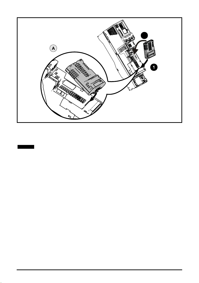
Figure 3-2 Installation of an SI option module on Unidrive M600 to M702
2
NOTE
• Move the option module in direction shown (1/2).
• Align and insert the option module tab in to the slot provided, this is highlighted in the detailed
view (A).
• Press down on the option module until it clicks into place.
Option module slots must be used in the following order: Slot 3 (lower), Slot 2 (middle)
and then Slot 1(upper).
12 SI-EtherCAT User Guide
Issue Number: 2
4 Electrical installation
NOTE
NOTE
information
Safety
4.1 SI-EtherCAT module information
4.1.1 Bus media
The SI-EtherCAT option module incorporates two 100 BASE-TX RJ45 interfaces.
4.1.2 Cabling considerations
To ensure long-term reliability it is recommended that any cables used to connect a system
together be tested using a suitable Ethernet cable tester, this is of particular importance when
cables are constructed on site.
4.1.3 Cable
Cables should be shielded and as a minimum, meet TIA Cat 5e requirements.
Cabling issues are the single biggest cause of network downtime. Ensure cabling is
correctly routed, wiring is correct, connectors are correctly installed and any switches or
routers used are rated for industrial use. Office grade Ethernet equipment does not
generally offer the same degree of noise immunity as equipment intended for industrial
use.
4.1.4 Maximum network length
The main restriction imposed on Ethernet cabling is the length of a single segment of cable. The SIEtherCAT module has two 100BASE-TX Ethernet ports, which support segment lengths of up to
100 m. This means that the maximum cable length which can be used between one SI-EtherCAT
port and another 100BASE-TX port is 100 m however it is not recommended that the full 100 m
cable length is used. The total network length is not restricted by the Ethernet standard but
depends on the number of devices on the network and the transmission media (copper, fiber optic,
etc.).
The EtherCAT system designer must consider the impact that the selected network
structure will have on performance.
Introduction
Mechanical
installation
installation
Electrical
Getting
started
Protocols
Drive profile (CiA402)
support
Advanced
features
SI-EtherCAT User Guide 13
Issue Number: 2
descriptions
Diagnostics
terms
Index
Parameter
Glossary of

4.2 SI-EtherCAT terminal descriptions
EtherCAT
Port A
EtherCAT
Port B
Ground
tab
Link LEDs
The SI-EtherCAT module has two RJ45 Ethernet ports for the EtherCAT network.
Figure 4-1 SI-EtherCAT connections
Table 4-1 EtherCAT terminal descriptions
Pin A - IN Pin B - OUT
1 Transmit + 1 Transmit +
2 Transmit - 2 Transmit -
3 Receive + 3 Receive +
4 Not used 4 Not used
5 Not used 5 Not used
6 Receive - 6 Receive -
7 Not used 7 Not used
8 Not used 8 Not used
4.3 Module grounding and EMC
SI-EtherCAT is supplied with a grounding tab on the module that should be connected to the
closest possible grounding point using the minimum length of cable. This will greatly improve the
noise immunity of the module.
It is recommended that the Ethernet cable should be of the shielded type, and connectors should
be shielded with a metal body. Tie-wrapping of the Ethernet cable's shield to the grounding bracket
of the drive is necessary.
At least one EMC Ferrite inductor should be installed near to each communication port of the SIEtherCAT module.
At least one EMC Ferrite inductor is necessary near the Master's (PC / PLC) EtherCAT Port. Proper
grounding of the EtherCAT cable's shield near the Master (PC / PLC) is necessary.
14 SI-EtherCAT User Guide
Issue Number: 2

Drive grounding brackets should be connected to each other by separate cables, and the cable
Master / PLC
Unidrive
M600
Distributed I/O
SI-EtherCAT
SI-EtherCAT
SI-EtherCAT
Unidrive
M700
Unidrive
M200
length should be as small as possible.
Please note EMC Ferrite inductors of the required specification are available from the following
supplier:
Manufacturer: WURTH ELEKTRONIK
Manufacturer Part No: 74271222
Order code: 1635620
Description: Ferrite core, Split type
information
Safety
Introduction
Mechanical
installation
4.4 Network topology
Control Techniques recommend implementing daisy chaining on EtherCAT networks (see Figure 4-
2). Other Ethernet network topologies can be used but care must be taken to ensure that the
system still operates within the constraints specified by the designer.
Figure 4-2 SI-EtherCAT daisy chain network topology
4.5 Minimum node-to-node cable length
There is no minimum length of cable recommended in the Ethernet standards. To avoid possible
problems it is recommended that you allow sufficient cable length to ensure good bend radii on
cables and avoid unnecessary strain on connectors.
installation
started
support
features
descriptions
Electrical
Getting
Protocols
Drive profile (CiA402)
Advanced
Parameter
Diagnostics
SI-EtherCAT User Guide 15
Issue Number: 2
terms
Index
Glossary of
5 Getting started
NOTE
NOTE
5.1 Quick start guide
This section is intended to provide a generic guide for setting up SI-EtherCAT with a master/
controller PLC. It will cover the basic steps required to get cyclic data communicating using the
CANopen over EtherCAT (CoE) protocol on the SI-EtherCAT module.
Table 5-1 PDO test mappings
RxPDO1 TxPDO1
Mapping 1
Mapping 2
Mapping 3 Pr 20.021 (32-bits) N/A
0x6040 (controlword)
(16-bits)
0x6042 (vl_target_velocity)
(16-bits)
It is strongly recommended that the latest firmware be used where possible to ensure
that all features are supported.
Due to the large number of different masters that support CoE, details cannot be provided for a
specific master. Generic support is available through your supplier or local Control Techniques
Drive Centre. Before contacting your supplier or local Control Techniques Drive Centre for support
please ensure you have read section 10 Diagnostics on page 94 of this manual and have checked
that the SDO/PDO configurations are correct.
5.1.1 SI-EtherCAT XML file
Control Techniques provides EtherCAT device description files (in the form of .xml files). These files
provide the master with information about the SI-EtherCAT module and drive configuration to aid
with its configuration. These files can be downloaded from the Control Techniques CTSupport.com
website or from your local Control Techniques Drive Centre or supplier. They should be placed in
the directory specified by the master e.g. when using TwinCAT this could be
C:\TwinCAT\Io\EtherCAT.
The master may have to be re-started for the file to be loaded.
0x6041 (statusword)
(16-bits)
0x6064 (position_actual_value)
(32-bits)
5.1.2 Configuring the SI-EtherCAT module for cyclic communications
Unlike other Control Techniques fieldbus communication protocols, CoE does not require that any
module parameters be changed in order to achieve communications. The baud rate of the network
is fixed and the module is automatically allocated an address.
To check that the ethernet cable connected to the SI-EtherCAT module on the drive is connected
correctly, look at the LED on the front of the SI-EtherCAT module relating to the connector being
used, if this light is a solid green color then a link is established with the master, if this light if off then
check the cabling and also check that the master has started communications.
In the master, scan the network ensuring that the SI-EtherCAT module is connected correctly to the
master. If the network is configured correctly the SI-EtherCAT node(s) should be visible in the PLC
master.
Decide on the input / output data you wish to send cyclically (objects and/or parameters).
Cyclic data is implemented on CoE networks by using "Process Data Objects" or PDOs. Separate
data objects are used for receiving (TxPDOs - from the slave to the master) and transmitting
(RxPDOs - from the master to the slave) data.
16 SI-EtherCAT User Guide
Issue Number: 2

0x6041
Status word
0x6064 position
actual value
TxPDO1
PLC
0x6040
Controlword
0x6042
vl_target_velocity
Pr 20.21
RxPDO1
NOTE
These PDOs contain the cyclic data (objects and/or parameters), the RxPDOs available are 1, 2, 3,
5 and 6, the TxPDOs available are 1, 2, 3, 5 and 6 (for more information on these PDOs including
default mappings please see section 6.3.2 RxPDO mappings on page 30 and section 6.3.3 TxPDO
mappings on page 34).
Figure 5-1 SI-EtherCAT PDO configuration
RxPDO1 and TxPDO1 will need to be enabled in the master. Once enabled you will need to add
mappings to the PDOs.
The format used when mapping objects to PDOs is as follows:
• Index: Object index number (0x0000)
• Sub-index: Object sub-index number (0x00)
• Size: Dependant on the size (in bytes) of the object to be mapped (range: 1-4)
The format used when mapping drive parameters to PDOs is as follows:
• Index: 0x2000 + (0x100 x S) + menu number
• Sub-index: 0x00 + parameter number
• Size: Dependant on the size (in bytes) of the object to be mapped (range: 1-4)
For example Pr 20.021 would be index 0x2014, sub-index 0x15 and the size would be 4 (the
parameter is a 32-bit signed value).
The values are normally expressed in hexadecimal, so care must be taken to enter the
correct parameter number.
For this example the following objects will need to be set in order to achieve the mappings of the
parameters/objects in the PDOs.
Table 5-2 Cyclic data mapping configuration
RxPDO1: TxPDO1:
Object: 0x1600 Object: 0x1A00
Sub-index: 0x00 Sub-index: 0x00
Size: 1 Size: 1
Value: 3 Value: 2
Sub-index: 0x01 Sub-index: 0x01
Size: 4 Size: 4
Value: 0x60400010 Value: 0x60410010
Sub-index: 0x02 Sub-index: 0x02
Size: 4 Size: 4
Value: 0x60420010 Value: 0x60640020
Sub-index: 0x03 Not Used
Size: 4
Value: 0x20141520
SI-EtherCAT User Guide 17
Issue Number: 2
information
Introduction
installation
installation
Getting started
Protocols
support
features
descriptions
Diagnostics
terms
Index
Safety
Mechanical
Electrical
Drive profile (CiA402)
Advanced
Parameter
Glossary of

The format used to define the value of a mapped object is as follows:
NOTE
NOTE
NOTE
0x1C12
0x6040
Controlword
0x6042
vl_target_velocity
RxPDO1
0x1C13
0x6041
Status word
0x6064
position
actual value
TxPDO1
PLC
Pr 20.021
Bit 0 to 7: Length of the mapped object in bits (if a gap, bit length of the gap).
Bit 8 to 15: Sub-index of the mapped object (if a gap, zero).
Bit 16 to 31: Index of the mapped object (if a gap, zero).
The maximum number of mappings in one PDO is twelve. There are no restrictions on
the data length of these parameters (i.e. It is possible to map twelve, 32-bit parameters
in one PDO). It is also possible to use a maximum of one RxPDOs and one TxPDOs.
For M200, M300 and M400 the maximum update time achievable is 4 ms.
5.1.3 Configuring the sync managers
The sync manager is used to control the transmission of CANopen PDOs over the EtherCAT
network.
The following objects 0x1C12 - sync manager 2 PDO assignment (RxPDO) and 0x1C13 - sync
manager 3 PDO assignment (TxPDO) are required to assign PDOs to the synchronization task. For
the purpose of the example assign one RxPDO to sync manager 2 and one TxPDOs to sync
manager 3.
Figure 5-2 SI-EtherCAT sync manager configuration
Assigning RxPDO to the sync manager
To assign RxPDO1 to sync manager 2 PDO assignment set the values below to the following
objects:
• Index: 0x1C12
• Sub index: 0x00
•Size: 1
•Value: 1
Setting object 0x1C12, sub-index 0 to a value of 1 (as above) indicates that one RxPDO will be
assigned to the sync manager 2 assignment.
• Index: 0x1C12
• Sub index: 0x01
•Size: 2
• Value: 0x1600
Setting object 0x1C12, sub-index 1 to a value of 0x1600 (as above) maps RxPDO1 to the process
data output sync.
18 SI-EtherCAT User Guide
Issue Number: 2

Assigning TxPDO to the sync manager
To assign TxPDO1 to sync manager 3 PDO assignment set the values below to the following
objects:
• Index: 0x1C13
• Sub index: 0x00
•Size: 1
•Value: 1
Setting object 0x1C13, sub-index 0 to a value of 1 (as above) indicates that one TxPDOs will be
assigned to the sync manager 3 assignment.
• Index: 0x1C13
• Sub index: 0x01
•Size: 2
• Value: 0x1A00
Setting object 0x1C13, sub-index 1 to a value of 0x1A00 (as above) maps TxPDO1 to the process
data input sync.
Download the configuration to the master.
After downloading the configuration to the master the LED(s) on the front of the SI-EtherCAT
should flash, depending on the port(s) connected.
Values written to parameters over RxPDOs should now be viewable using the drive’s keypad so
long as the master has put the slave into the operational state; also, parameter values changed
using the drive keypad will be updated on the master.
information
Safety
Introduction
Mechanical
installation
installation
Electrical
Getting started
Protocols
Drive profile (CiA402)
support
SI-EtherCAT User Guide 19
Issue Number: 2
features
descriptions
Diagnostics
terms
Index
Advanced
Parameter
Glossary of
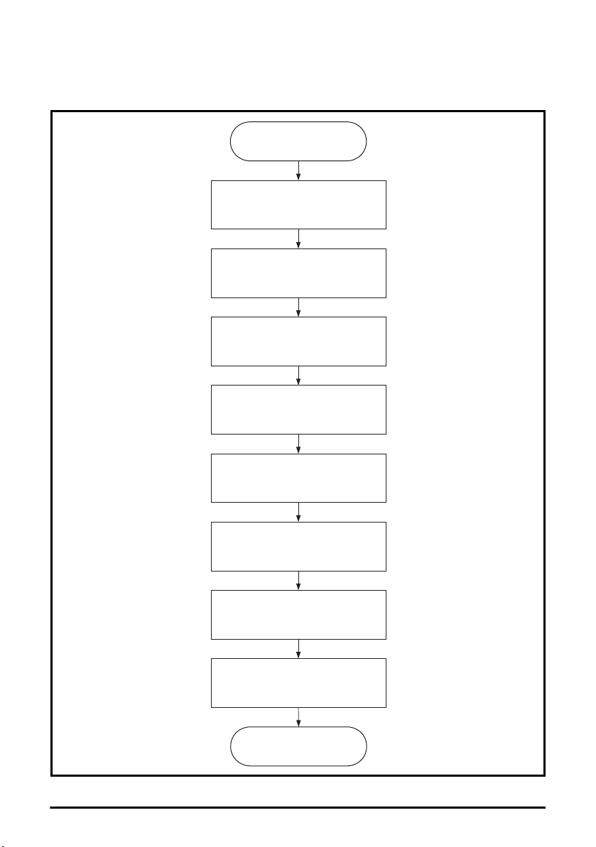
5.2 Quick start flowchart
Ensure the Control Techniques .xml fileisin
the appropriate folder on the hard drive of the
master
Check the LED status of the SI-EtherCAT
module
In the master, scan the EtherCAT network
Select required PDOs
Configure the PDOs with the mappings
required
Check the front of the SI-EtherCAT module
to ensure that the LED relating to the
connection being used is flashing, this
confirms that communications are functioning
Download or activate the configuration to the
master
Configure the Sync managers using the
required PDOs
END
START
Figure 5-3 details the steps required to achieve cyclic communications on the EtherCAT network.
This flowchart should be used as the starting point for all configurations.
Figure 5-3 Quick start flowchart
20 SI-EtherCAT User Guide
Issue Number: 2

5.3 Supported objects
Table 5-3 lists the objects currently supported by SI-EtherCAT
Table 5-3 SI-EtherCAT Object Dictionary
Profile
information
Safety
Introduction
Interpolated Position
Cyclic Sync Velocity
Data Type
Object Ref.
(0x)
1000 Device type 0 UDINT RO Y Y Y Y Y Y
1001 Error register 0 USINT RO Y Y Y Y Y Y
1018
1600
1601
1602
1604
1605
1A00
1A01
Description
Sub-index Type
Identity object
(Number of last sub-index)
Identity object (Vendor ID) 1
Identity object (Product Code) 2
Identity object (Software Version) 3
(Reserved) 4 UDINT RO Y Y Y Y Y Y
Receive PDO mapping 1
(Number of objects)
Receive PDO mapping 1
(Mapped object 1 to si0)
Receive PDO mapping 2
(Number of objects)
Receive PDO mapping 2
(Mapped object 1 to si0)
Receive PDO mapping 3
(Number of objects)
Receive PDO mapping 3
(Mapped object 1 to si0)
Receive PDO mapping 5
(Number of objects)
Receive PDO mapping 5
(Mapped object 1 to si0)
Receive PDO mapping 6
(Number of objects)
Receive PDO mapping 6
(Mapped object 1 to si0)
Transmit PDO mapping 1
(Number of objects)
Transmit PDO mapping 1
(Mapped object 1 to si0)
Transmit PDO mapping 2
(Number of objects)
Transmit PDO mapping 2
(Mapped object 1 to si0)
0
0 USINT RW Y Y Y Y Y Y
1 to si0 UDINT RW Y Y Y Y Y Y
0 USINT RW Y Y Y Y Y Y
1 to si0 UDINT RW Y Y Y Y Y Y
0 USINT RW Y Y Y Y Y Y
1 to si0 UDINT RW Y Y Y Y Y Y
0 USINT RW Y Y Y Y Y Y
1 to si0 UDINT RW
0 USINT RW Y Y Y Y Y Y
1 to si0 UDINT RW
0 USINT RW
1 to si0 UDINT RW
0 USINT RW Y Y Y Y Y Y
1 to si0 UDINT RW Y Y Y Y Y Y
USINT
UDINT
UDINT
UDINT
Access
Velocity
Homing
RO Y Y Y Y Y Y
RO Y Y Y Y Y Y
RO Y Y Y Y Y Y
RO Y Y Y Y Y Y
Y Y Y Y Y Y
Y Y Y Y Y Y
Y Y Y Y Y Y
Y Y Y Y Y Y
Cyclic Sync Position
Cyclic Sync Torque
installation
installation
Getting started
Protocols
support
features
descriptions
Diagnostics
terms
Index
Mechanical
Electrical
Drive profile (CiA402)
Advanced
Parameter
Glossary of
SI-EtherCAT User Guide 21
Issue Number: 2

Profile
Object Ref.
(0x)
1A02
1A04
1A05
1C00
1C10
1C11
1C12
1C13
1C14
Description
Transmit PDO mapping 3
(Number of objects)
Transmit PDO mapping 3
(Mapped object 1 to si0)
Transmit PDO mapping 5
(Number of objects)
Transmit PDO mapping 5
(Mapped object 1 to si0)
Transmit PDO mapping 6
(Number of objects)
Transmit PDO mapping 6
(Mapped object 1 to si0)
Sync manager communication type
(Number of SM protocols)
Sync manager communication type
(SM0 Usage)
Sync manager communication type
(SM1 Usage)
Sync manager communication type
(SM2 Usage)
Sync manager communication type
(SM3 Usage)
Sync manager communication type
(SM4 Usage)
Sync manager communication type
(SM5 Usage)
SM0 PDO assignment
(Number of PDOs)
SM1 PDO assignment
(Number of PDOs)
SM2 PDO assignment
(Number of PDOs)
SM2 PDO assignment
(Assigned PDO index)
SM3 PDO assignment
(Number of PDOs)
SM3 PDO assignment
(Assigned PDO index)
SM4 PDO assignment
(Number of PDOs)
SM4 PDO assignment
(Assigned PDO index)
Interpolated Position
Cyclic Sync Velocity
Data Type
Sub-index Type
0 USINT RW
1 to si0 UDINT RW Y Y Y Y Y Y
0 USINT RW Y Y Y Y Y Y
1 to si0 UDINT RW Y Y Y Y Y Y
0 USINT RW Y Y Y Y Y Y
1 to si0 UDINT RW Y Y Y Y Y Y
0 USINT RO Y Y Y Y Y Y
1 USINT RO Y Y Y Y Y Y
2 USINT RO Y Y Y Y Y Y
3 USINT RO Y Y Y Y Y Y
4 USINT RO Y Y Y Y Y Y
5 USINT RO Y Y Y Y Y Y
6 USINT RO
0 USINT RO
0 USINT RO Y Y Y Y Y Y
0 USINT RW Y Y Y Y Y Y
1UINTRW
0 USINT RW
1UINTRWY Y Y Y Y Y
0 USINT RW Y Y Y Y Y Y
1UINTRWY Y Y Y Y Y
Access
Velocity
Y Y Y Y Y Y
Y Y Y Y Y Y
Y Y Y Y Y Y
Y Y Y Y Y Y
Y Y Y Y Y Y
Cyclic Sync Torque
Homing
Cyclic Sync Position
22 SI-EtherCAT User Guide
Issue Number: 2

Profile
information
Safety
Interpolated Position
Cyclic Sync Velocity
Data Type
Object Ref.
(0x)
1C15
2smm
3000 Position feedback encoder configuration 0 USINT RW Y Y Y Y Y Y
3003
3004
3005
3006
3007
3008 Activate velocity mode redirection 0 USINT RW Y N N Y N N
603F Error code 0 UINT RO Y Y Y Y Y Y
6040 Control word 0 UINT WO Y Y Y Y Y Y
Description
SM5 PDO assignment
(Number of PDOs)
SM5 PDO assignment
(Assigned PDO index)
Drive parameter access
(s = slot 0x0 to 0xF,
mm=menu 0x00 to 0xFF)
Homing source
(Number of last sub-index)
Homing source
(Homing switch source)
Homing source
(Freeze/marker source)
Additional position loop scaling
(Number of last sub-index)
Additional position loop scaling
(Numerator)
Additional position loop scaling
(Denominator)
Cyclic data loss behaviour
(Number of last sub-index)
Cyclic data loss behaviour
(Timeout (ms))
Cyclic data loss behaviour
(Action)
Out cyclic data configuration
(Number of last sub-index)
Out cyclic data configuration
(Copy to drive task)
Out cyclic data configuration
(Copy from master task)
In cyclic data configuration
(Number of last sub-index)
In cyclic data configuration
(Copy from drive task)
In cyclic data configuration
(Copy to master task)
Sub-index Type
0 USINT RW
1UINTRWY Y Y Y Y Y
pp
(pp=par
0x00 to
0xFF)
0 USINT RO NNYNNN
1 USINT RW NNYNNN
2 USINT RW NNYNNN
0 USINT RO NYNNNY
1 DINT RW NY NNNY
2 DINT RW NY NNNY
0 USINT RO Y Y Y Y Y Y
1 UINT RWYYYYYY
2 USINT RW Y Y Y Y Y Y
0 USINT RO Y Y Y Y Y Y
1 USINT RW Y Y Y Y Y Y
2 USINT RW Y Y Y Y Y Y
0 USINT RO Y Y Y Y Y Y
1 USINT RW Y Y Y Y Y Y
2 USINT RW Y Y Y Y Y Y
[var] RWYYYYYY
Access
Velocity
Homing
Y Y Y Y Y Y
Cyclic Sync Position
Cyclic Sync Torque
Introduction
installation
installation
Getting started
Protocols
support
features
descriptions
Diagnostics
terms
Index
Mechanical
Electrical
Drive profile (CiA402)
Advanced
Parameter
Glossary of
SI-EtherCAT User Guide 23
Issue Number: 2

Profile
Interpolated Position
Cyclic Sync Velocity
Data Type
Object Ref.
(0x)
6041 Status word 0 UINT RO Y Y Y Y Y Y
6042 vl_target_velocity 0 INT RW Y N N N N N
6043 vl_velocity_demand 0 INT RO Y N N N N N
6044 vl_velocity_actual_value 0 INT RO Y N N N N N
6046
6048
6049
604A
604B
604C
Description
vl_velocity_min_max_
amount
(Number of last sub-index)
vl_velocity_min_max_
amount
(Minimum velocity (rpm))
vl_velocity_min_max_
amount
(Maximum velocity (rpm))
vl_velocity_acceleration
(Number of last sub-index)
vl_velocity_acceleration
(Delta speed value (rpm))
vl_velocity_acceleration
(Delta time value (s))
vl_velocity_deceleration
(Number of last sub-index)
vl_velocity_deceleration
(Delta speed value (rpm))
vl_velocity_deceleration
(Delta time value (s))
vl_velocity_quick_stop
(Number of last sub-index)
vl_velocity_ quick_stop
(Delta speed value (rpm))
vl_velocity_ quick_stop
(Delta time value (s))
vl_setpoint_factor
(Number of last sub-index)
vl_setpoint_factor
(Numerator)
vl_setpoint_factor
(Denominator)
vl_dimension_factor
(Number of last sub-index)
vl_dimension_factor
(Numerator)
vl_dimension_factor
(Denominator)
Sub-index Type
0 USINT RO Y N N N N N
1 UDINT RW Y N N N N N
2 UDINT RW Y N N N N N
0 USINT RO Y N N N N N
1 UDINT RW Y N N N N N
2 UINT RW Y NNNNN
0 USINT RO Y N N N N N
1 UDINT RW Y N N N N N
2 UINT RW Y NNNNN
0 USINT RO Y N N N N N
1 UDINT RW Y N N N N N
2 UINT RW Y NNNNN
0 USINT RO Y N N N N N
1 INT RW Y N N N N N
2 INT RW Y N N N N N
0 USINT RO Y N N N N N
1 INT RW Y N N N N N
2 INT RW Y N N N N N
Access
Velocity
Homing
Cyclic Sync Position
Cyclic Sync Torque
24 SI-EtherCAT User Guide
Issue Number: 2

Profile
information
Safety
Interpolated Position
Cyclic Sync Velocity
Data Type
Object Ref.
(0x)
605A Quick stop option code 0 UINT RW Y Y Y Y Y Y
605B Shutdown option code 0 UINT RW Y Y Y Y Y Y
605C Disable operation option code 0 UINT RW Y Y Y Y Y Y
605E Fault reaction option code 0 UINT RW Y Y Y Y Y Y
6060 Modes of operation 0 USINT RW Y Y Y Y Y Y
6061 Modes of operation display 0 USINT RO Y Y Y Y Y Y
6062 Position demand value 0 DINT RO Y Y Y Y Y Y
6064 Position actual value 0 DINT RO Y Y Y Y Y Y
6065 Following error window 0 UDINT RW N Y N N N Y
6067 Position window 0 UDINT RW N Y N N N Y
606C Velocity actual value 0 DINT RO Y Y Y Y Y Y
6071 Target torque 0 INT RW N N N N Y N
6073 Max current 0 UINT RW Y Y Y Y Y Y
6075 Motor rated current 0 UDINT RO Y Y Y Y Y Y
6077 Torque actual value 0 INT RO Y Y Y Y Y Y
6078 Current actual value 0 INT RO Y Y Y Y Y Y
607A Target position 0 DINT RW N N N N N Y
607C Home offset 0 DINT RW N N Y N N N
6080 Max motor speed 0 UDINT RW Y Y Y Y Y Y
6084 Profile deceleration 0 UDINT RW N Y N Y Y Y
6085 Quick stop deceleration 0 UDINT RW N Y N N N Y
608F
6091
6092
Description
Position encoder resolution
(Number of last sub-index)
Position encoder resolution
(Encoder increments)
Position encoder resolution
(Motor revolutions)
Gear ratio
(Number of last sub-index)
Gear ratio
(Motor revolutions)
Gear ratio
(Shaft revolutions)
Feed constant
(Number of last sub-index)
Feed constant
(Feed value)
Feed constant
(Shaft revolutions)
Sub-index Type
0 USINT RO NYNNNY
1 UDINT RO N Y N N N Y
2 UDINT RO N Y N N N Y
0 USINT RO Y Y Y Y Y Y
1 UDINT RW Y Y Y Y Y Y
2 UDINT RW Y Y Y Y Y Y
0 USINT RO Y Y Y Y Y Y
1 UDINT RW Y Y Y Y Y Y
2 UDINT RW Y Y Y Y Y Y
Access
Velocity
Homing
Cyclic Sync Position
Cyclic Sync Torque
Introduction
installation
installation
Getting started
Protocols
support
features
descriptions
Diagnostics
terms
Index
Mechanical
Electrical
Drive profile (CiA402)
Advanced
Parameter
Glossary of
SI-EtherCAT User Guide 25
Issue Number: 2

Profile
Interpolated Position
Cyclic Sync Velocity
Data Type
Object Ref.
(0x)
6098 Homing method 0 USINT RW N N Y N N N
6099
609A Homing acceleration 0 UDINT RW N N Y N N N
60B1 Velocity offset 0 DINT RW N N N Y N N
60B2 Torque offset 0 INT RW N N N Y Y Y
60C0 Interpolation sub-mode select 0 INT RW N Y N Y Y Y
60C1
60C2
60F4 Following error actual value 0 DINT RO N Y N N N Y
60FB
60FF Target velocity 0 DINT RW N N N Y N N
6502 Supported drive modes 0 UDINT RO Y Y Y Y Y Y
Description
Homing speeds
(Number of last sub-index)
Homing speeds
(Speed during switch search)
Homing speeds
(Speed during zero point search)
Interpolation data record
(Number of last sub-index)
Interpolation data record
(Target position)
Interpolation time period
(Number of last sub-index)
Interpolation time period
(Number of time periods)
Interpolation time period
(Time period exponent)
Position control parameter set
(Number of last sub-index)
Position control parameter set
(Proportional gain)
Position control parameter set
(Speed feed forward gain)
Sub-index Type
0 USINT RO NNYNNN
1 UDINT RW N N Y N N N
2 UDINT RW N N Y N N N
0 USINT RO N Y N Y Y N
1 UDINT RW N Y N Y Y N
0 USINT RO N Y N Y Y Y
1 USINT RW N Y N Y Y Y
2 SINT RW NYNYYY
0 USINT RO N Y N Y Y Y
1 DINT RO NYNYYY
2 DINT RO NYNYYY
Access
Velocity
Homing
Cyclic Sync Position
Cyclic Sync Torque
26 SI-EtherCAT User Guide
Issue Number: 2
6 Protocols
NOTE
NOTE
NOTE
information
Safety
6.1 Process Data Objects (PDOs)
Cyclic data is implemented on EtherCAT networks by using "Process Data Objects" or PDOs.
Separate data objects are used for transmitting (TxPDOs) and receiving (RxPDOs) data. PDO
configuration objects are usually pre-configured in the EtherCAT master controller and downloaded
to the SI-EtherCAT at network Initialization using SDOs.
6.2 Service Data Object (SDO) parameter access
The service data object (SDO) provides access to all objects in the EtherCAT object dictionary and
the drive parameters are mapped into the object dictionary as 0x2XXX objects in the following way:
Index: 0x2000 + menu
Sub-index: parameter
For example Pr 20.021 would be index 0x2014 and the sub-index would be 0x15. The values are
usually expressed in base 16 (hexadecimal), so care must be taken to enter the correct parameter
number.
All other supported entries in the SI-EtherCAT object dictionary can also be accessed using SDOs.
Refer to the master controller documentation for full details about implementing SDO transfers
within the particular master controller.
Bit parameter mapping
When mapping to drive bit parameters, the parameter is stored in the drive as an 8-bit value,
therefore for correct operation, the data type SINT (short integer) should be used for mapping to
these parameters.
The following table shows the drive bit parameter value for a given value in the EtherCAT master.
EtherCAT Value
Decimal Hex (0x)
-128 to 0 80 to 00 0 (Off)
1 to 127 01 to 7F 1 (On)
Parameter Value
Introduction
Mechanical
installation
installation
Electrical
Getting started
Protocols
Drive profile (CiA402)
support
Advanced
features
This is contrary to other option modules where any value other than zero will result in
the parameter being set to a 1 (On).
Sub-index 0 for any menu will return the highest sub-index available for the object (i.e.
the highest parameter number).
The following SDO services are supported:
• Initiate SDO Download (Write)
• Initiate SDO Upload (Read)
• Abort SDO Transfer (Error)
SI-EtherCAT User Guide 27
Issue Number: 2
descriptions
Diagnostics
terms
Index
Parameter
Glossary of
6.3 CANopen over EtherCAT (CoE)
The CoE protocol over EtherCAT uses a modified form of the CANopen object dictionary. This is
specified in Table 6-1.
Table 6-1 CoE object dictionary
The object description format describes object related information such as size, range and
descriptions and is detailed in Table 6-2.
Table 6-2 Object description format
<index> <object name>
Sub-index 0
Access: <access> Range: <range> Size: <size> Unit: <unit>
Default: <default> Type: <type>
Description: <description>
For entries having sub-indices
Table 6-3 Object description format with sub-indices
<index> <object name>
Sub-index 0
Access: <access> Range: <range> Size: <size> Unit: <unit>
Default: <default> Type: <type>
Description: <description>
Sub-index 1
Access: <access> Range: <range> Size: <size> Unit: <unit>
Default: <default> Type: <type>
Description: <description>
Sub-index …
Access: <access> Range: <range> Size: <size> Unit: <unit>
Default: <default> Type: <type>
Description: <description>
Sub-index n-1
Access: <access> Range: <range> Size: <size> Unit: <unit>
Default: <default> Type: <type>
Description: <description>
Sub-index n
Access: <access> Range: <range> Size: <size> Unit: <unit>
Default: <default> Type: <type>
Description: <description>
Definitions:
• <index>: A signed 16-bit number. This is the index of the object dictionary entry specified
in four hexadecimal characters.
Index Object dictionary area
0x0000 to 0x0FFF Data type area
0x1000 to 0x1FFF CoE communication area
0x2000 to 0x5FFF Manufacturer specific area
0x6000 to 0x9FFF Profile area
0xA000 to 0xFFFF Reserved area
28 SI-EtherCAT User Guide
Issue Number: 2

• <access>: A value describing how the object may be accessed (RW = read/write, RO =
read-only and WO = write-only).
• <size>: The size of the object/sub-index in bytes.
• <unit>: The physical unit (e.g. ms, counts per second etc.).
• <type>: Data type:-
Data type
Size
(bytes)
USINT 1 0 to 255 Unsigned short integer
SINT 1 -128 to 127 Signed short integer
UINT 2 0 to 65535 Unsigned integer
INT 2 -32768 to 32767 Signed integer
UDINT 4
DINT 4
Range Description
32
Unsigned double integer
Signed double integer
-2
0 to 2
31
to 231-1
6.3.1 CoE communication area
The first set of objects specify general communication settings.
Table 6-4 Device type object
0x1000 Device type
Access: RO Range: N/A Size: 4 bytes Unit: N/A
Default:
Description:
Dependent on drive type / mode (see
description).
Type: UDINT
The primary CoE functional profile is CiA402, so the value of this object is defined as follows:
Bits 0 to 15 (Device Profile Number): 402
Bit 16 (Frequency Converter): x
Bit 17 (Servo Drive): y
Bit 18 (Stepper Motor): 0
Bit 24 (DC Drive - Control Techniques specific): 0
Bits 25-31 (Manufacturer specific): 0
This value will be dependent on the drive operating mode and / or type. On Unidrive M600 and
above in the open-loop, RFC-A or Regen modes or on Unidrive M200 - M400, bit 16 will be set,
while bit 17 will be clear. On Unidrive M600 and above in RFC-S mode, bit 17 will be set, while
bit 16 will be clear.
information
Safety
Introduction
Mechanical
installation
installation
Electrical
Getting started
Protocols
Drive profile (CiA402)
support
Advanced
features
SI-EtherCAT User Guide 29
Issue Number: 2
descriptions
Diagnostics
terms
Index
Parameter
Glossary of

Table 6-5 Identity object
0x1018 Identity object
Sub-index 0
Access: RO Range: N/A Size: 1 byte Unit: N/A
Default: 4 Type: USINT
Description: The number of the last sub-index in this object.
Sub-index 1
Access: RO Range: N/A Size: 4 bytes Unit: N/A
Default: 0x000000F9 (249) Type: UDINT
Description:
Sub-index 2
Access: RO Range: N/A Size: 4 bytes Unit: N/A
Default: 0x01mmvvtt Type: UDINT
Description:
Sub-index 3
Access: RO Range: N/A Size: 4 bytes Unit: N/A
Default: Derived from Pr S.00.002 Type: UDINT
Description: Module firmware version in the format major.minor.version.build
Sub-index 4
Access: RO Range: N/A Size: 4 bytes Unit: N/A
Default: 0 Type: UDINT
Description: A value of zero will be returned rather than the module serial number
This contains the EtherCAT Technology Group vendor ID for Control Techniques
(0x000000F9).
Product code.
This contains the drive product code.
Byte0 (tt): Drive type (0 = Leroy Somer; 1 = Mentor MP; 2 = M600/M700; 3 = M100 to M400;
4 = MEV; 5 = Elevator ES)
Byte1 (vv): Drive variant/derivative (derived from Pr 11.028)
Byte2 (mm): Drive mode (derived from Pr 11.08 4)
Byte3 (gg): Drive generation (0 = Unidrive SP; 1 = Unidrive M)
6.3.2 RxPDO mappings
Objects with indices from 0x1600 to 0x17FF specify receive PDO mappings. The mappings from
CiA402 are included as standard (the PDO mappings will have the following default values).
Table 6-6 RxPDO mappings
PDO No. Mapped object indices Mapped default object names
1 0x6040 controlword
2
3
5
6
0x6040
0x6060
0x6040
0x607A
0x6040
0x6071
0x6040
0x6042
controlword
modes_of_operation
controlword
target_position
controlword
target_torque
controlword
vl_target_velocity
The RxPDO mapping objects are defined in the following tables. Each mapping object has the
maximum number of sub-indices (each representing an object mapped to a PDO) defined in the
XML configuration file (specified as “CF” in the following descriptions).
30 SI-EtherCAT User Guide
Issue Number: 2
 Loading...