


User Guide
SI-DeviceNet
Part Number: 0478-0032-02
Issue Number: 2

General Information
The manufacturer accepts no liability for any consequences resulting from inappropriate, negligent or
incorrect installation or adjustment of the optional parameters of the equipment or from mismatching
the variable speed drive with the motor.
The contents of this guide are believed to be correct at the time of printing. In the interests of
commitment to a policy of continuous development and improvement, the manufacturer reserves the
right to change the specification of the product or its performance, or the content of the guide without
notice.
All rights reserved. No parts of this guide may be reproduced or transmitted in any form or by any
means, electrical or mechanical including, photocopying, recording or by an information storage or
retrieval system, without permission in writing from the publisher.
Environmental Statement
Control Techniques is committed to minimising the environmental impacts of its manufacturing
operations and of its products throughout their life cycle. To this end, we operate an Environmental
Management System (EMS) which is certified to the International Standard ISO 14001. Further
information on the EMS, our Environment Policy and other relevant information is available on
request, or can be found at www.greendrives.com.
The electronic variable speed drives manufactured by Control Techniques have the potential to save
energy and (through increased machine/process efficiency) reduce raw material consumption and
scrap throughout their long working lifetime. In typical applications, these positive environmental
effects far outweigh the negative impacts of product manufacture and end-of-life disposal.
Nevertheless, when the products eventually reach the end of their useful life, they must not be
discarded but should instead be recycled by a specialist recycler of electronic equipment. Recyclers
will find the products easy to dismantle into their major component parts for efficient recycling. Many
parts snap together and can be separated without the use of tools, while other parts are secured with
conventional fasteners. Virtually all parts of the product are suitable for recycling.
Product packaging is of good quality and can be re-used. Large products are packed in wooden
crates, while smaller products come in strong cardboard cartons which themselves have a highrecycled fibre content. If not re-used, these containers can be recycled. Polythene, used on the
protective film and bags from wrapping product, can be recycled in the same way. Control
Techniques' packaging strategy prefers easily recyclable materials of low environmental impact, and
regular reviews identify opportunities for improvement.
When preparing to recycle or dispose of any product or packaging, please observe local legislation
and best practice.
Software Statement
This Option module is supplied with the latest software version. When retro-fitting to an existing
system, all software versions should be verified to confirm the same functionality as Option modules
of the same type already present. This also applies to products returned from a Control Techniques
Service Centre or Repair Centre. If there is any doubt please contact the supplier of the product.
The software version of the Option module can be identified by looking at Pr MM.002 where MM is
the relevant menu number for the Option module slot being used. See Pr MM.002 description later in
this manual for more information. The software version takes the form of ww.xx.yy.zz seen in
MM.002.
REACH legislation
EC Regulation 1907/2006 on the Registration, Evaluation, Authorisation and restriction of Chemicals
(REACH) requires the supplier of an article to inform the recipient if it contains more than a specified
proportion of any substance which is considered by the European Chemicals Agency (ECHA) to be a
Substance of Very High Concern (SVHC) and is therefore listed by them as a candidate for
compulsory authorisation.
For current information on how this requirement applies in relation to specific Control Techniques
products, please approach your usual contact in the first instance. Control Techniques position
statement can be viewed at:
http://www.controltechniques.com/REACH
Copyright : © January 2013 Control Techniques Ltd.
Issue Number : 1
For patent and intellectual property related information please go to www.ctpatents.info

Contents
1 Safety information ..........................................................5
1.1 Warnings, Cautions and Notes ................................................................5
1.2 Electrical safety - general warning ..........................................................5
1.3 System design and safety of personnel ..................................................5
1.4 Environmental limits ................................................................................6
1.5 Compliance with regulations ...................................................................6
1.6 Adjusting parameters ..............................................................................6
2 Introduction ....................................................................7
2.1 What Is DeviceNet? .................................................................................7
2.2 What is SI-DeviceNet? ............................................................................9
2.3 General specification ...............................................................................9
2.4 Back-up power supply ............................................................................. 9
2.5 Option Module identification .................................................................. 10
2.6 Product Conformance Certificate ..........................................................10
2.7 Conventions used in this guide .............................................................10
3 Mechanical installation ................................................11
3.1 General installation ................................................................................11
4 Electrical installation ...................................................12
4.1 SI-DeviceNet terminal descriptions .......................................................12
4.2 SI-DeviceNet connections ..................................................................... 13
4.3 DeviceNet cable ....................................................................................13
4.4 DeviceNet network termination .............................................................14
4.5 SI-DeviceNet cable shield connections ................................................. 14
4.6 DeviceNet ground point ......................................................................... 15
4.7 Maximum network length ......................................................................15
4.8 Spurs .....................................................................................................15
4.9 Minimum node to node cable length .....................................................15
5 Getting started ..............................................................16
5.1 Quick start chart SI-DeviceNet .............................................................. 17
5.2 Parameter save and restore ..................................................................18
5.3 Module reset ..........................................................................................18
5.4 Restoring module parameter default values ..........................................18
5.5 Single Line Parameters ......................................................................... 18
6 Parameters .................................................................... 25
6.1 Menus ....................................................................................................25
6.2 Module menu 0 - Module Information ....................................................25
6.3 Module menu 1 - DeviceNet Setup .......................................................28
6.4 Module menu 2 - Input Mappings .......................................................... 40
6.5 Module menu 3 - Output Mappings ....................................................... 41
6.6 Module menu 4 - Fault Values ..............................................................42
7 Non cyclic data .............................................................44
7.1 Introduction ............................................................................................44
7.2 Explicit parameter access .....................................................................44
SI-DeviceNet User Guide 3
Issue Number: 2

8 Control / status word ...................................................45
8.1 What are control and status words? ......................................................45
8.2 Control word .......................................................................................... 45
8.3 Status word ...........................................................................................47
9 EDS Files .......................................................................49
9.1 What are EDS files? .............................................................................. 49
9.2 Generic EDS files .................................................................................. 49
10 Advanced Features ......................................................50
10.1 Supported Drive assembly objects ........................................................50
11 DeviceNet Objects ........................................................ 54
11.1 Identity Object .......................................................................................54
11.2 SI-DeviceNet Object ..............................................................................57
11.3 Motor Data Object .................................................................................59
11.4 Control Supervisor .................................................................................62
11.5 AC/DC Drive Object ..............................................................................65
11.6 Control Techniques Object ....................................................................68
12 Diagnostics ...................................................................69
12.1 Overview ...............................................................................................69
13 Glossary Of Terms .......................................................73
4 SI-DeviceNet User Guide
Issue Number: 2

1 Safety information
WARNING
CAUT ION
NOTE
information
Safety
1.1 Warnings, Cautions and Notes
A Warning contains information, which is essential for avoiding a safety hazard.
A Caution contains information, which is necessary for avoiding a risk of damage to the
product or other equipment.
A Note contains information which helps to ensure correct operation of the product.
1.2 Electrical safety - general warning
The voltages used in the drive can cause severe electrical shock and/or burns, and
could be lethal. Extreme care is necessary at all times when working with or adjacent to
the drive.
Specific warnings are given at the relevant places in this User Guide.
1.3 System design and safety of personnel
The drive is intended as a component for professional incorporation into complete
equipment or a system. If installed incorrectly, the drive may present a safety hazard.
The drive uses high voltages and currents, carries a high level of stored electrical
energy, and is used to control equipment which can cause injury. Close attention is
required to the electrical installation and the system design to avoid hazards either in
normal operation or in the event of equipment malfunction. System design, installation,
Commissioning/start-up and maintenance must be carried out by personnel who have
the necessary training and experience. They must read this safety information and this
User Guide carefully.
The STOP and SAFE TORQUE Off functions of the drive do not isolate dangerous
voltages from the output of the drive or from any external option unit. The supply must
be disconnected by an approved electrical isolation device before gaining access to the
electrical connections.
With the sole exception of the SAFE TORQUE Off function, none of the drive
functions must be used to ensure safety of personnel, i.e. they must not be used
for safety-related functions.
Careful consideration must be given to the functions of the drive which might result in a
hazard, either through their intended behavior or through incorrect operation due to a
fault. In any application where a malfunction of the drive or its control system could lead
to or allow damage, loss or injury, a risk analysis must be carried out, and where
necessary, further measures taken to reduce the risk - for example, an over-speed
protection device in case of failure of the speed control, or a fail-safe mechanical brake
in case of loss of motor braking.
The system designer is responsible for ensuring that the complete system is safe
and designed correctly according to the relevant safety standards.
Introduction
Mechanical
installation
installation
Electrical
Getting
started
Parameters
Non cyclic
data
status word
Control /
EDS Files
Advanced
Features
DeviceNet
Objects
Diagnostics
Glossary Of
Ter m s
Index
SI-DeviceNet User Guide 5
Issue Number: 2

1.4 Environmental limits
Instructions in the Unidrive M User Guide regarding transport, storage, installation and
use of the drive must be complied with, including the specified environmental limits.
Drives must not be subjected to excessive physical force.
1.5 Access
Drive access must be restricted to authorized personnel only. Safety regulations which
apply at the place of use must be complied with.
1.6 Compliance with regulations
The installer is responsible for complying with all relevant regulations, such as national
wiring regulations, accident prevention regulations and electromagnetic compatibility
(EMC) regulations. Particular attention must be given to the cross-sectional areas of
conductors, the selection of fuses or other protection, and protective earth (ground)
connections.
The Unidrive M User Guide contains instructions for achieving compliance with specific
EMC standards.
Within the European Union, all machinery in which this product is used must comply
with the following directives:
• 2006/42/EC: Safety of machinery.
• 2004/108/EC: Electromagnetic Compatibility.
1.7 Adjusting parameters
Some parameters have a profound effect on the operation of the drive. They must not
be altered without careful consideration of the impact on the controlled system.
Measures must be taken to prevent unwanted changes due to error or tampering.
1.7.1 Stored charge
The drive contains capacitors that remain charged to a potentially lethal voltage after the
AC supply has been disconnected. If the drive has been energized, the AC supply must
be isolated at least ten minutes before work may continue.
6 SI-DeviceNet User Guide
Issue Number: 2

2 Introduction
Hardwired controller
1
2
Digital 1ADigital 1B
Digital 2A Digital 2B
Digital 1A Digital 1B Digital 2A Digital 2B
Analog 1 Analog 2
Analog 1
Analog 2
information
Safety
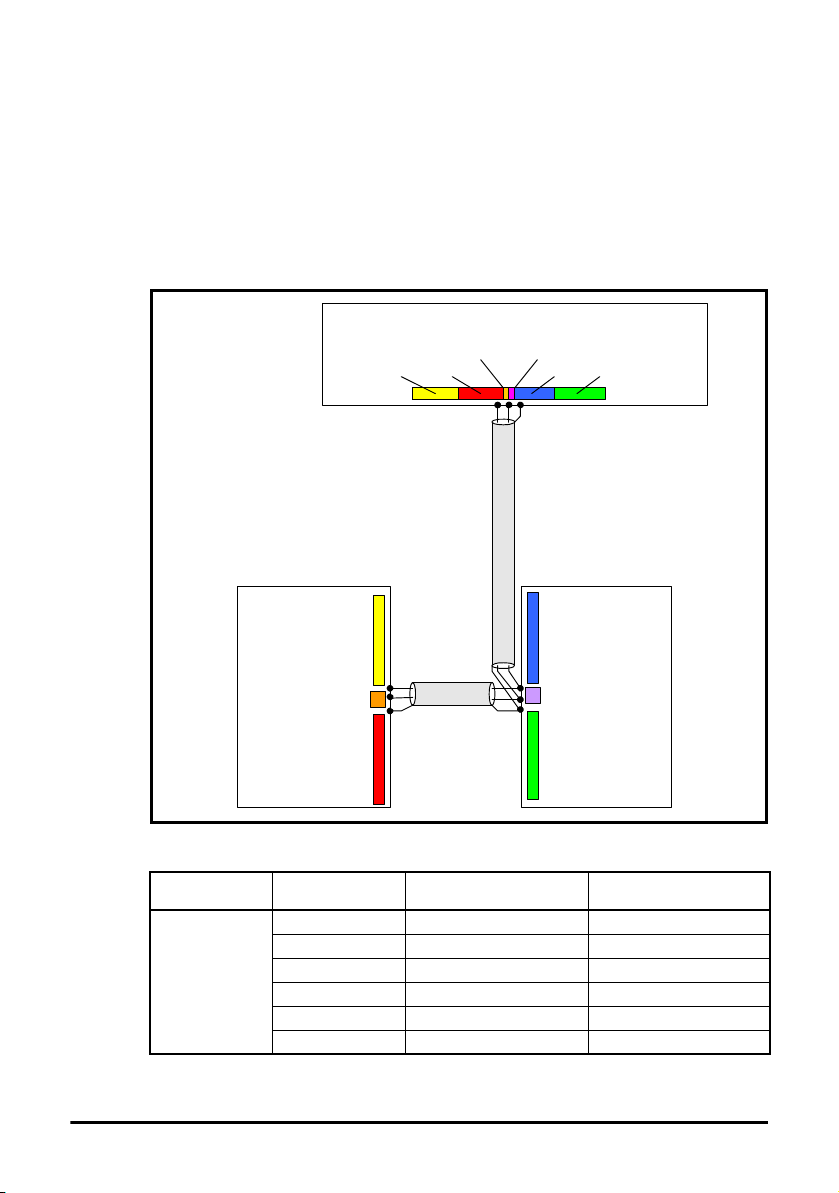
2.1 What Is DeviceNet?
DeviceNet is a networking system that falls into the generic category of Fieldbus.
Fieldbuses are generally defined as industrial networking systems that are intended to
replace traditional wiring systems. Figure 2-1 shows the traditional cabling requirements
to transfer signals between a controller and two nodes.
Figure 2-1 SI-DeviceNet Traditional cable layout
Introduction
installation
installation
started
Parameters
data
status word
EDS Files
Mechanical
Electrical
Getting
Non cyclic
Control /
Table 2.1 details how the wiring is used to communicate data between the controller and
the nodes. Each signal that is communicated requires one signal wire giving a total of 66
signal wires plus a 0V return.
Table 2.1 Traditional wiring details
Number of
signals
16
16
SI-DeviceNet User Guide 7
Issue Number: 2
Type Source / Destination Description
digital inputs node 1 to master status signals
digital outputs controller to slave 1 control signals
1
analog output controller to slave 1 control signal
digital inputs node 2 to master status signals
digital outputs controller to slave 2 control signals
1
analog output controller to slave 2 control signal
Features
Objects
Te rm s
Advanced
DeviceNet
Diagnostics
Glossary Of
Index
A fieldbus topology such as DeviceNet allows the same configuration to be realised
DeviceNet master
Digital 1A Digital 1B Digital 2A Digital 2B
Analog 1
Digital 2A Digital 2B
Digital 1ADigital 1B
Node 1
Node 2
Analog 2
Analog 1
Analog 2
using only 2 signal wires plus a shield and power. This method of communication saves
significantly on the amount of cabling required and can improve overall system
reliability, as the number of inter-connections is greatly reduced.
Figure 2-2 shows a typical DeviceNet system transferring the same signals as given in
the traditionally wired example. The signals are now transmitted by converting them into
a serial data stream which is received by the master as if they were connected using
traditional wiring. The data stream on DeviceNet allows up to 56 (28 input and 28
output) independent values to be sent or received by the master, there are also methods
available (non-cyclic data) to allow random access to drive parameters.
Figure 2-2 DeviceNet overview
Table 2.2 Data mappings for SI-DeviceNet
Number of
network words
1
8 SI-DeviceNet User Guide
Type Source / Destination Description
digital inputs slave 1 to master status signals
digital outputs master to slave 1 control signals
analog output master to slave 1 control signal
digital inputs slave 2 to master status signals
digital outputs master to slave 2 control signals
analog output master to slave 2 control signal
Issue Number: 2
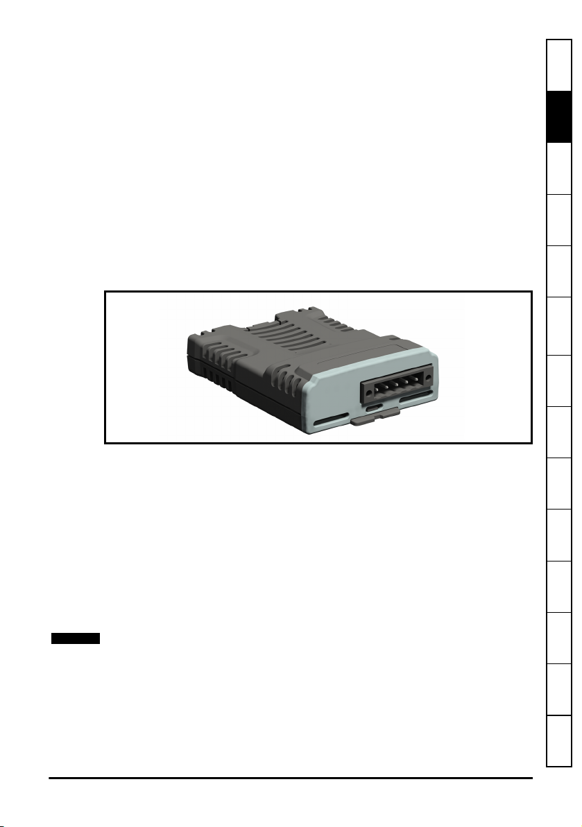
Table 2.2 details the number of data words used to communicate the signals using the
NOTE
DeviceNet network. It can be seen that the resulting reduction in cabling is significant.
DeviceNet can transfer data using two distinct modes. The first of these modes is cyclic
where signals are sent in predefined blocks at regular intervals. This is the equivalent of
the hard-wired example above in Figure 2-1.
The second method of transfer is called non-cyclic data and is used for sending values
that only need to be changed occasionally or where the source or destination of the
signal changes; this is the equivalent of a temporary patch lead that is removed after
use.
information
Introduction
installation
Safety
Mechanical
2.2 What is SI-DeviceNet?
SI-DeviceNet is a fieldbus Option Module which can be installed to the expansion slot(s)
in Unidrive M to provide DeviceNet slave connectivity.
It is possible to use more than one SI-DeviceNet or a combination of SI-DeviceNet and
other Option Modules to provide additional functionality such as extended I/O, gateway
functionality, or additional PLC features.
Figure 2-3 SI-DeviceNet Option Module
2.3 General specification
• Supported data rates (bits per s): 500 k, 250 k, 125 k.
• 1 to 28 input/output polled data words supported.
• Explicit communications (non-cyclic) provides access to all drive parameters.
• 8 pre-defined DeviceNet profiles supported.
2.4 Back-up power supply
The required drive can be connected to a back-up power supply. This keeps the control
electronics and Option Module powered up, allowing the SI-DeviceNet to continue
communicating with the DeviceNet master controller when the line power to the drive is
switched off.
The back-up supply is provided through the drive and not the connections on SIDeviceNet, which have an alternative use.
installation
started
Parameters
data
status word
EDS Files
Features
Objects
Diagnostics
Te rm s
Electrical
Getting
Non cyclic
Control /
Advanced
DeviceNet
Glossary Of
Index
SI-DeviceNet User Guide 9
Issue Number: 2

2.5 Option Module identification
1
2
SI-DeviceNet
SI-DeviceNet can be identified by:
1. The label located on the top of the Option Module.
2. The color coding across the front of the SI-DeviceNet (dark grey).
Figure 2-4 SI-DeviceNet labels
1 Topside module label
2 Underside module label
2.5.1 Date code format
The date code is split into two sections: a letter followed by a number. The letter
indicates the year, and the number indicates the week number (within the year) in which
the Option Module was built.The letters go in alphabetical order, starting with A in 1990
(B in 1991, C in 1992 etc).
Example:
A date code of V35 would correspond to week 35 of year 2012.
2.6 Product Conformance Certificate
2.7 Conventions used in this guide
10 SI-DeviceNet User Guide
SI-DeviceNet has been awarded full DeviceNet Conformance Certification by the Open
DeviceNet Vendors Association (ODVA). A copy of the certificate is available on request
from your supplier or local Control Techniques Drive Centre.
The configuration of the host drive and Option Module is done using menus and
parameters. A menu is a logical collection of parameters that have similar functionality.
In the case of an Options Module, the parameters will appear in menu 15, 16 or 17
depending on which slot the module is installed to. The menu is determined by the
number before the decimal point.
The method used to determine the menu or parameter is as follows:
•Pr S.mm.ppp - Where S signifies the Option module slot number and mm.ppp
signifies the menu and parameter number of the Option module's internal menus
and parameters.
•Pr MM.ppp - Where MM signifies the menu allocated to the Option module set-up
menu and ppp signifies the parameter number.
•Pr mm.000 - Signifies parameter number 000 in any drive menu.
Issue Number: 2

3 Mechanical installation
WARNING
information
Safety
Before installing or removing an Option module from any drive, ensure the
AC supply has been disconnected for at least 10 minutes and refer to
section 1 Safety information on page 5. If using a DC bus supply ensure
this is fully discharged before working on any drive or Option module.
3.1 General installation
The installation of an Option module is illustrated in Figure 3-1.
Figure 3-1 Installing an Option module
12
3.1.1 Installing the first Option module
• Option module slots must be used in the following order: slot 3, slot 2 and slot 1.
Orientate the Option module above the drive as shown in (1).
• Align and insert the Option module tab into the slot (2). Press down on the Option
module until it clicks into place.
Introduction
Mechanical
installation
installation
Electrical
Getting
started
Parameters
Non cyclic
data
status word
Control /
EDS Files
Advanced
Features
SI-DeviceNet User Guide 11
Issue Number: 2
DeviceNet
Objects
Diagnostics
Glossary Of
Ter m s
Index

4 Electrical installation
5
1
NOTE
CAUT ION
4.1 SI-DeviceNet terminal descriptions
SI-DeviceNet has a standard 5-way screw terminal block connector (shown on the right)
for the DeviceNet network.
Figure 4-1 SI-DeviceNet - connector view
Table 4.1 SI-DeviceNet terminal descriptions
5-way
terminal
1 0 V 0 V DeviceNet external supply
2 CAN-L Negative data line
3 Shield Cable braided shield connection
4 CAN-H Positive data line
5 +24 V +24 V DeviceNet external supply
The external supply terminals provide power for the DeviceNet transceiver circuitry, but
do NOT provide power to keep the SI-DeviceNet operating in the event of the mains power supply loss to the drive. An external supply will keep the DeviceNet transceivers powered up and the network load characteristics constant in the event of loss of power to the
drive.
Any external supply must be suitably installed to prevent noise on the network.
Connecting pins 1 and 5 to an external supply allows the line driver circuitry to remain
powered when the drive and the SI-DeviceNet module are turned off. This 24 V input
does not allow SI-DeviceNet to continue communicating.
Function Description
12 SI-DeviceNet User Guide
Issue Number: 2

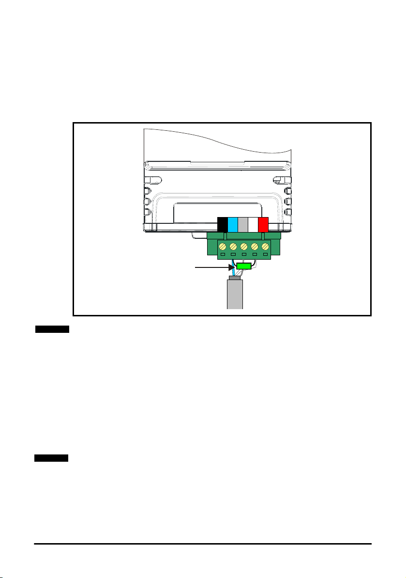
4.2 SI-DeviceNet connections
Cable
1 2 3 4 5
SI-DeviceNet
2125576532
NOTE
To connect SI-DeviceNet to the DeviceNet network, make the connections as shown in
the diagram below. The length of the "pigtail" shield connection must be kept as short as
possible.
Figure 4-2 SI-DeviceNet connections
information
installation
installation
started
data
Safety
Introduction
Mechanical
Electrical
Getting
Parameters
Non cyclic
4.3 DeviceNet cable
DeviceNet cable has 2 twisted pairs plus an overall shielding. DeviceNet has a specified
color code, and it is important that this code is maintained. The data wires are white and
blue, and the network power supply wires are red and black.
Table 4.2 DeviceNet cable color codes
Terminal Cable Data signal
1 Black 0V 0 V external power supply
2 Blue CAN-L Negative data line
3 Braided Shield Shield Cable shield
4 White CAN-H Positive data line
5 Red +24 V +24 V external power supply
DeviceNet networks run at high data rates and require cable specifically designed to
carry high frequency signals. Low quality cable will attenuate the signals and may
render the signal unreadable for the other nodes on the network. Cable specifications
and a list of approved manufacturers of cable for use on DeviceNet networks is
available on the Open DeviceNet Vendors Association web site at www.odva.org.
Control Techniques can only guarantee correct and reliable operation of SI-DeviceNet if
all other equipment installed on the DeviceNet network (including the network cable) has
been approved by the ODVA.
SI-DeviceNet User Guide 13
Issue Number: 2
Description
status word
Control /
EDS Files
Advanced
Features
DeviceNet
Objects
Diagnostics
Glossary Of
Te rm s
Index
4.4 DeviceNet network termination
Cable
SI-DeviceNet
2125576532
1 2 3 4 5
120
0.25 W
Ω
NOTE
NOTE
It is very important in high-speed communications networks that the network
communications cable is installed with the specified termination resistor network at each
end of the cable segment. This prevents signals from being reflected back down the
cable and causing interference.
During installation of a DeviceNet network, 120 Ω 0.25 W termination resistors should
be installed across the CAN-H and CAN-L lines at both ends of the network segment, as
shown in Figure 4-3 below.
Figure 4-3 DeviceNet network termination
Failure to terminate a network correctly can seriously affect the operation of the network.
If the correct termination resistors are not installed, the noise immunity of the network is
greatly reduced.
If too many termination resistors are installed on a DeviceNet network, the network will
be over-loaded, resulting in reduced signal levels. This may cause nodes to miss some
bits of information, resulting in potential transmission errors.
4.5 SI-DeviceNet cable shield connections
The SI-DeviceNet should be wired with the cable shields isolated from ground at each
drive. The cable shields should be linked together at the point where they emerge from
the cable, and formed into a short pigtail to be connected to pin 3 on the DeviceNet
connector.
The DeviceNet cable can be tie-wrapped to the grounding bar or local convenient mounting that is not live to provide strain relief, but the DeviceNet cable shield must be kept
isolated from ground at each node. The only exception to this is the DeviceNet ground
point. Refer to section 4.6 DeviceNet ground point on page 15.
14 SI-DeviceNet User Guide
Issue Number: 2

4.6 DeviceNet ground point
The DeviceNet cable shield must be grounded AT ONE POINT only, usually near the
centre point of the cable run. This is to prevent the cable shield from becoming live in
the event of catastrophic failure of another device on the DeviceNet network.
4.7 Maximum network length
The maximum number of nodes that can be connected to a single DeviceNet network
segment is 64. The maximum length of network cable for a DeviceNet network is
specified by the Open DeviceNet Vendors Association and depends on the data rate to
be used.
Table 4.3 DeviceNet maximum segment lengths
Data rate (bits/sec) Maximum network length (m)
1 M 30
800 k 50
500 k 100
250 k 250
125 k 500
100 k 700
50 k 1000
20 k 2500
10 k 5000
4.8 Spurs
Control Techniques do not recommend the use of spurs on a DeviceNet network.
information
installation
installation
started
data
status word
Safety
Introduction
Mechanical
Electrical
Getting
Parameters
Non cyclic
Control /
EDS Files
4.9 Minimum node to node cable length
The DeviceNet specification does not specify a minimum node to node distance,
however, Control Techniques advises a minimum distance of 1 m between nodes to
prevent excessive bend radii and to reduce network reflections.
SI-DeviceNet User Guide 15
Issue Number: 2
Advanced
Features
DeviceNet
Objects
Diagnostics
Glossary Of
Te rm s
Index

5 Getting started
NOTE
NOTE
This section is intended to provide a generic guide for setting up SI-DeviceNet and a
master controller/PLC. Figure 5.1 Quick start chart SI-DeviceNet on page 17 is intended
as the starting point for a new installation. The following pages detail the various
methods available to configure SI-DeviceNet. It is recommended that all of this section
is read, before attempting to configure a system.
It is recommended that the latest firmware is used where possible to ensure all features
are supported.
Due to the large number of different PLCs/masters that support DeviceNet, details
cannot be provided for any specific master or PLC. Generic support is available through
your supplier or local drive centre. Before contacting your supplier or local drive centre
for support ensure you have read Chapter 12 Diagnostics on page 69 of this manual and
check you have configured all parameters correctly.
Ensure the following information is available before calling:
• A list of all parameters in SI-DeviceNet
• The drive firmware version (see the drive documentation)
• The SI-DeviceNet firmware version
16 SI-DeviceNet User Guide
Issue Number: 2

5.1 Quick start chart SI-DeviceNet
Set node address
(Pr ) to a
unique address
(not 63)
S.01.004
Set DeviceNet
data rate
(Pr )
S.01.005
Start
END
Configure mappings
(Pr -
Pr
and Pr
- )
S.02.001
S.02.028
S.03.001
S.03.028
Perform a drive
save (Pr
= save parameters
or 1000) and
press reset
mm.000
Reset Option
module
(Pr =On)
MM.007
Configure PLC to
expect drive at
address set in
(Pr )
S.01.004
Configure PLC
network data rate
to match drive
Map the data from
the network into
the PLC program
Place the PLC in
“Run Mode”
Communications
functional, write
PLC code
Ensure PLC
correctly
configured
Is Pr
=“Init Failed”?
S.01.006
Remove power
then re-install
Option module
Is a SlotX Error
present?
Check the
sub-string
then find error
code in manual
For drives on 24 V only use 1001
no yes
yes
no
no
Is Pr >0 ?
S.01.007
information
Safety
Introduction
Mechanical
installation
installation
Electrical
Getting
started
Parameters
Non cyclic
data
status word
Control /
EDS Files
Advanced
Features
DeviceNet
Objects
Diagnostics
Glossary Of
Te rm s
Index
SI-DeviceNet User Guide 17
Issue Number: 2

5.2 Parameter save and restore
Parameters in the module are saved when a normal drive parameter save is initiated by
selecting "Save Parameters" or setting a value of 1000 in Pr mm.000 and performing a
drive reset. (If the drive is in the under voltage state or is supplied from a low voltage
power supply then a value of 1001 must be set in Pr mm.000 and a drive reset
performed).
Any user-saved parameters in the option module's internal menus are stored in nonvolatile memory on the module and not in the drive. Therefore, if the module is moved to
a different slot or to a different drive, then any saved parameter values will follow the
module. If a module is to be replaced, ensure that the parameter values for the module
have been backed up before replacing it.
5.3 Module reset
A reset of the SI-DeviceNet module can be performed by the methods detailed below.
•Set Pr S.00.007 (or Pr MM.007) to On (1). This will only reset the module in slot S.
• Select "Reset modules" or set a value of 1070 in Pr mm.000, and performing a drive
reset. This will perform a reset of all option modules installed in the drive.
5.4 Restoring module parameter default values
Setting Pr S.00.008 (or Pr MM.008) to On (1) and performing a module reset will return
all parameters in the SI-DeviceNet module to their default values.
Parameters in the SI-DeviceNet module will also be set to their default values when
drive parameters are returned to their default values.
5.5 Single Line Parameters
Table 5.1 Menu 0 Setup
Parameter Range(Ú) Default(Ö)Type
MM.001 Module ID 0 to 999 447 RO Num ND NC PT
MM.002 Software Version
MM.003 Hardware Version 00.00 to 99.99
MM.004 Serial Number LS 0 to 99999999
MM.005 Serial Number MS 0 to 99999999 RO Num ND NC PT
MM.006 Module status
MM.007 Module reset Off (0) or On (1) Off (0) RW Bit NC
MM.008 Module default Off (0) or On (1) Off (0) RW Bit NC
00.00.00.00
to
99.99.99.99
Initialising (0), OK (1),
Config (2), Error (3)
RO Num ND NC PT
RO Num ND NC PT
RO Num ND NC PT
RO Num ND NC PT
18 SI-DeviceNet User Guide
Issue Number: 2

Table 5.2 Menu 1 DeviceNet setup
Parameter Range(Ú)Default(Ö)Type
S.01.001
S.01.002
S.01.003
S.01.004
S.01.005 Baud rate
S.01.006
S.01.007
S.01.010 Timeout delay 0 to 9999 ms 200 ms RW Num US
S.01.011 Timeout action
S.01.012
S.01.013 Timeout event
S.01.014 Data alignment 32 (0) or 16 (1) bits 32 (0) bits RW Txt US
S.01.018
S.01.019
S.01.020
S.01.021
S.01.022
S.01.023
S.01.024
S.01.025
S.01.026
S.01.027
Enable DeviceNet
Interface
Reset DeviceNet
Interface
Default DeviceNet
Interface
DeviceNet node
address
DeviceNet Network
Diagnostic
Cyclic data transfers per second
Timeout event destination
Input Cyclic Assembly Object ID
Output Cyclic
Assembly Object ID
Input cyclic mapping length
Output cyclic mapping length
Input mapping status
Output mapping
status
Input processing
time
Output processing
time
Input consistency
enable
Input consistency
trigger parameter
Off (0) or On (1) On (1) RO Bit NC
Off (0) or On (1) Off (0) RW Bit NC
Off (0) or On (1) Off (0) RW Bit NC
0 to 63 63 RW Num US
Auto Detect (-1), 125 kbps (0), 250
kbps (1), 500 kbps (2)
Network OK (0), Init OK (1), No
Cyclic (2), Init Failed (3), Comm
Fault (4), No 24 V (5), Baud
detecting (6), Initialising (7)
0 to 9999 messages/s
125 kbps
(0)
RW Txt US
RO Txt ND NC PT
RO Num ND NC PT
Trip (0), Send flt values (1), Clear
output (2), Hold last (3), No action
(4)
This slot (0), Slot 1 (1), Slot 2 (2),
Slot 3 (3), Slot 4 (4)
No event (0), Event 0 (1), Event 1
(2), Event 2 (3), Event 3 (4), Event
4 (5)
Trip (0) RW Txt US
This slot
No event
RW Txt US
(0)
RW Txt US
(0)
70-73, 106-160 (even) 112 RW Num US
20-23, 107-161 (odd) 113 RW Num US
1 to 28 4 RO Num
1 to 28 4 RO Num
No error (0), Par Impossible (1),
Hole in mapping (2), Dup mapping
(3), Length exceed (4), Obj not
support (5), Pre & uncompress (6),
Type Unmatched (7), Memory fault
No error
(0)
RO Txt NC PT
(8), No mapping (9)
No error (0), Par Impossible (1),
Hole in mapping (2), Dup mapping
(3), Length exceed (4), Obj not
support (5), Pre & uncompress (6),
Type Unmatched (7), Memory fault
(8), No mapping (9)
0 to 65535 ms
0 to 65535 ms
No error
(0)
RO Txt NC PT
RO Num ND
RO Num ND
Disable (0) or Enable (1) Disable (0) RW Bit US
0 to 4.99.999 0.00.000 RW DE PT US
information
Safety
Introduction
Mechanical
installation
installation
Electrical
Getting
started
Parameters
Non cyclic
data
status word
Control /
EDS Files
Advanced
Features
DeviceNet
Objects
Diagnostics
Glossary Of
Te rm s
Index
SI-DeviceNet User Guide 19
Issue Number: 2

S.01.028
S.01.029
S.01.031
S.01.032
S.01.034 Bus Off trip Enable (0) or Disable (1) Enable (0) RW Txt US
S.01.040 Motor 1 Type
S.01.041 Motor 2 Type
Output consistency
enable
Output consistency
trigger parameter
Custom product
type
Custom product
version
Disable (0) or Enable (1) Disable (0) RW Bit US
0 to 4.99.999 0.00.000 RW DE PT US
Unidrive M (0) or Unidrive SP (1)
0 to 9999 0 RW Num US
FC DC Motor (2), WRI motor (6),
SCI motor (7), Sin PM BL motor (9),
Trap PM BL motor (10)
FC DC Motor (2), WRI motor (6),
SCI motor (7), Sin PM BL motor (9),
Trap PM BL motor (10)
Unidrive M
SCI motor
SCI motor
RW Txt US
(0)
RO Txt PT US
(7)
RO Txt PT US
(7)
20 SI-DeviceNet User Guide
Issue Number: 2

Table 5.3 Menu 2 Input mapping
Parameter Range(Ú)Default(Ö)Type
S.02.001 Input mapping parameter 1 0 to 499999 10040 RW Num DE PT US
S.02.002 Input mapping parameter 2 0 to 499999 2001 RW Num DE PT US
S.02.003 Input mapping parameter 3 0 to 499999 0 RW Num DE PT US
S.02.004 Input mapping parameter 4 0 to 499999 0 RW Num DE PT US
S.02.005 Input mapping parameter 5 0 to 499999 0 RW Num DE PT US
S.02.006 Input mapping parameter 6 0 to 499999 0 RW Num DE PT US
S.02.007 Input mapping parameter 7 0 to 499999 0 RW Num DE PT US
S.02.008 Input mapping parameter 8 0 to 499999 0 RW Num DE PT US
S.02.009 Input mapping parameter 9 0 to 499999 0 RW Num DE PT US
S.02.010 Input mapping parameter 10 0 to 499999 0 RW Num DE PT US
S.02.011 Input mapping parameter 11 0 to 499999 0 RW Num DE PT US
S.02.012 Input mapping parameter 12 0 to 499999 0 RW Num DE PT US
S.02.013 Input mapping parameter 13 0 to 499999 0 RW Num DE PT US
S.02.014 Input mapping parameter 14 0 to 499999 0 RW Num DE PT US
S.02.015 Input mapping parameter 15 0 to 499999 0 RW Num DE PT US
S.02.016 Input mapping parameter 16 0 to 499999 0 RW Num DE PT US
S.02.017 Input mapping parameter 17 0 to 499999 0 RW Num DE PT US
S.02.018 Input mapping parameter 18 0 to 499999 0 RW Num DE PT US
S.02.019 Input mapping parameter 19 0 to 499999 0 RW Num DE PT US
S.02.020 Input mapping parameter 20 0 to 499999 0 RW Num DE PT US
S.02.021 Input mapping parameter 21 0 to 499999 0 RW Num DE PT US
S.02.022 Input mapping parameter 22 0 to 499999 0 RW Num DE PT US
S.02.023 Input mapping parameter 23 0 to 499999 0 RW Num DE PT US
S.02.024 Input mapping parameter 24 0 to 499999 0 RW Num DE PT US
S.02.025 Input mapping parameter 25 0 to 499999 0 RW Num DE PT US
S.02.026 Input mapping parameter 26 0 to 499999 0 RW Num DE PT US
S.02.027 Input mapping parameter 27 0 to 499999 0 RW Num DE PT US
S.02.028 Input mapping parameter 28 0 to 499999 0 RW Num DE PT US
information
Safety
Introduction
Mechanical
installation
installation
Electrical
Getting
started
Parameters
Non cyclic
data
status word
Control /
EDS Files
Advanced
Features
DeviceNet
Objects
Diagnostics
SI-DeviceNet User Guide 21
Issue Number: 2
Glossary Of
Te rm s
Index

Table 5.4 Menu 3 Output mapping
Parameter Range(Ú) Default(Ö)Type
S.03.001 Output mapping parameter 1 0 to 499999 6042 RW Num DE PT US
S.03.002 Output mapping parameter 2 0 to 499999 1021 RW Num DE PT US
S.03.003 Output mapping parameter 3 0 to 499999 0 RW Num DE PT US
S.03.004 Output mapping parameter 4 0 to 499999 0 RW Num DE PT US
S.03.005 Output mapping parameter 5 0 to 499999 0 RW Num DE PT US
S.03.006 Output mapping parameter 6 0 to 499999 0 RW Num DE PT US
S.03.007 Output mapping parameter 7 0 to 499999 0 RW Num DE PT US
S.03.008 Output mapping parameter 8 0 to 499999 0 RW Num DE PT US
S.03.009 Output mapping parameter 9 0 to 499999 0 RW Num DE PT US
S.03.010 Output mapping parameter 10 0 to 499999 0 RW Num DE PT US
S.03.011 Output mapping parameter 11 0 to 499999 0 RW Num DE PT US
S.03.012 Output mapping parameter 12 0 to 499999 0 RW Num DE PT US
S.03.013 Output mapping parameter 13 0 to 499999 0 RW Num DE PT US
S.03.014 Output mapping parameter 14 0 to 499999 0 RW Num DE PT US
S.03.015 Output mapping parameter 15 0 to 499999 0 RW Num DE PT US
S.03.016 Output mapping parameter 16 0 to 499999 0 RW Num DE PT US
S.03.017 Output mapping parameter 17 0 to 499999 0 RW Num DE PT US
S.03.018 Output mapping parameter 18 0 to 499999 0 RW Num DE PT US
S.03.019 Output mapping parameter 19 0 to 499999 0 RW Num DE PT US
S.03.020 Output mapping parameter 20 0 to 499999 0 RW Num DE PT US
S.03.021 Output mapping parameter 21 0 to 499999 0 RW Num DE PT US
S.03.022 Output mapping parameter 22 0 to 499999 0 RW Num DE PT US
S.03.023 Output mapping parameter 23 0 to 499999 0 RW Num DE PT US
S.03.024 Output mapping parameter 24 0 to 499999 0 RW Num DE PT US
S.03.025 Output mapping parameter 25 0 to 499999 0 RW Num DE PT US
S.03.026 Output mapping parameter 26 0 to 499999 0 RW Num DE PT US
S.03.027 Output mapping parameter 27 0 to 499999 0 RW Num DE PT US
S.03.028 Output mapping parameter 28 0 to 499999 0 RW Num DE PT US
22 SI-DeviceNet User Guide
Issue Number: 2

Table 5.5 Menu 4 Fault values
Parameter Range(Ú)Default(Ö)Type
S.04.001 Output Fault value 1
S.04.002 Output Fault value 2
S.04.003 Output Fault value 3
S.04.004 Output Fault value 4
S.04.005 Output Fault value 5
S.04.006 Output Fault value 6
S.04.007 Output Fault value 7
S.04.008 Output Fault value 8
S.04.009 Output Fault value 9
S.04.010 Output Fault value 10
S.04.011 Output Fault value 11
S.04.012 Output Fault value 12
S.04.013 Output Fault value 13
S.04.014 Output Fault value 14
S.04.015 Output Fault value 15
S.04.016 Output Fault value 16
S.04.017 Output Fault value 17
S.04.018 Output Fault value 18
S.04.019 Output Fault value 19
S.04.020 Output Fault value 20
S.04.021 Output Fault value 21
S.04.022 Output Fault value 22
S.04.023 Output Fault value 23
S.04.024 Output Fault value 24
S.04.025 Output Fault value 25
S.04.026 Output Fault value 26
S.04.027 Output Fault value 27
S.04.028 Output Fault value 28
-2
-2
-2
-2
-2
-2
-2
-2
-2
-2
-2
-2
-2
-2
-2
-2
-2
-2
-2
-2
-2
-2
-2
-2
-2
-2
-2
-2
31
to 231-1
31
to 231-1
31
to 231-1
31
to 231-1
31
to 231-1
31
to 231-1
31
to 231-1
31
to 231-1
31
to 231-1
31
to 231-1
31
to 231-1
31
to 231-1
31
to 231-1
31
to 231-1
31
to 231-1
31
to 231-1
31
to 231-1
31
to 231-1
31
to 231-1
31
to 231-1
31
to 231-1
31
to 231-1
31
to 231-1
31
to 231-1
31
to 231-1
31
to 231-1
31
to 231-1
31
to 231-1
0RWNum US
0RWNum US
0RWNum US
0RWNum US
0RWNum US
0RWNum US
0RWNum US
0RWNum US
0RWNum US
0RWNum US
0RWNum US
0RWNum US
0RWNum US
0RWNum US
0RWNum US
0RWNum US
0RWNum US
0RWNum US
0RWNum US
0RWNum US
0RWNum US
0RWNum US
0RWNum US
0RWNum US
0RWNum US
0RWNum US
0RWNum US
0RWNum US
information
Safety
Introduction
Mechanical
installation
installation
Electrical
Getting
started
Parameters
Non cyclic
data
status word
Control /
EDS Files
Advanced
Features
DeviceNet
Objects
Diagnostics
Glossary Of
Te rm s
Index
SI-DeviceNet User Guide 23
Issue Number: 2

Table 5.6 Menu 9 Resources
Parameter Range(Ú)Default(Ö)Type
S.09.030 PCB temperature
-128 to 127
0
C
RO Num ND NC PT
24 SI-DeviceNet User Guide
Issue Number: 2

6 Parameters
6.1 Menus
Table 6.1 below details each of the module's internal menus.
Table 6.1 SI-DeviceNet Internal Menu descriptions
Menu Description
S.0 Module information
S.1 DeviceNet setup
S.2 Input mapping
S.3 Output mappings
S.4 Fault values
S.9 Resources
S is the slot number where the module is installed.
The module's menu 0 is also displayed in menu 15, 16 or 17 on the drive depending on
which slot the module is installed in. Table 6.2 below shows the location of module's
menu 0 on the drive.
Table 6.2 SI-DeviceNet menu 0 locations on the drive
Slot number Menu 0 location
115
216
317
6.2 Module menu 0 - Module Information
All parameters in S.00.ppp (i.e. menu 0 within the Option module menus) are also
present in menus 15, 16 or 17 depending on the slot that the module is installed to e.g.
Pr 3.00.007 is also present as 17.007.
The functionality and properties of the parameters are identical between the two menus.
Module ID code
Default 447
S.00.001
Range 0 to 999
Access RO
installation
installation
started
data
status word
Features
Objects
Parameters Introduction
Mechanical
Electrical
Getting
Parameters
Non cyclic
Control /
EDS Files
Advanced
DeviceNet
Pr S.00.001 displays the ID number for the Option Module. For SI-DeviceNet, this is
447.
SI-DeviceNet firmware version
Default N/A
S.00.002
Range 00.00.00.00 to 99.99.99.99
Access RO
The firmware version of the Option module is in the format of ww.xx.yy.zz
SI-DeviceNet User Guide 25
Issue Number: 2
Diagnostics
Glossary Of
Te rm s
Index

SI-DeviceNet hardware version
Default N/A
S.00.003
The hardware version of the Option module is in the format of yy.zz
Serial Number LS
S.00.004
Serial Number MS
S.00.005
The module serial number is available as a pair of 32-bit values where Serial Number
LS (Pr S.00.004) provide the least significant 8 decimal digits, and Serial Number MS
(Pr S.00.005) provides the most significant 8 decimal digits. The reconstructed serial
number is ((S.00.005 x 100000000) + S.00.004). For example serial number
“0001234567898765” would be stored as S.00.005 = 12345 and S.00.004 = 67898765.
Module Status
S.00.006
This parameter displays the current status of the module. All possible values are shown
in the table below.
Value Text Description
0 Initializing Module is currently initializing.
1 Ok Module has initialized and has found no errors.
2Config
3 Error
Range 00.00 to 99.99
Access RO
Default N/A
Range 0 to 99999999
Access RO
Default N/A
Range 0 to 99999999
Access RO
Default N/A
Range Initializing (0) to Error (3)
Access RO
A configuration error has been detected in one of the
communications protocols or user program.
An error has occurred preventing the firmware or user
program from running correctly.
26 SI-DeviceNet User Guide
Issue Number: 2

Reset module
NOTE
Default Off (0)
S.00.007
Range Off (0) or On (1)
Access RW
Changes to the SI-DeviceNet configuration will not take effect until the SI-DeviceNet
has been reset.
To reset the SI-DeviceNet:
•Set Pr S.00.007 to On (1).
• When the sequence has been completed, Pr S.00.007 will be reset to Off (0).
• The SI-DeviceNet will reset using the updated configuration.
This sequence does NOT store the SI-DeviceNet configuration parameters in the drive
or the SI-DeviceNet flash memory. This parameter will change back to Off immediately,
and as such the change may not be visible on the display.
Default DeviceNet Interface
Default Off (0)
S.00.008
Range Off (0) or On (1)
Access RW
If the host drive is defaulted (see the drive user guide for details), it will also clear the
current configuration for the slot SI-DeviceNet is installed to.
This can be performed as follows:
•Set Pr S.00.008 to On (1).
• Reset the module by setting Pr S.00.007 to On (1).
• SI-DeviceNet communications will be stopped.
• Default parameter values for the SI-DeviceNet will be loaded.
• The SI-DeviceNet will reset using the default values.
installation
installation
started
data
status word
Parameters Introduction
Mechanical
Electrical
Getting
Parameters
Non cyclic
Control /
EDS Files
SI-DeviceNet User Guide 27
Issue Number: 2
Advanced
Features
DeviceNet
Objects
Diagnostics
Glossary Of
Te rm s
Index

6.3 Module menu 1 - DeviceNet Setup
NOTE
Menu 1 contains all the parameters relating to the setup of the DeviceNet interface on
the SI-DeviceNet module.
Enable DeviceNet Interface
Default On (1)
S.01.001
This parameter displays a value of On (1) to indicate that the DeviceNet Interface has
been enabled.
Reset DeviceNet Interface
S.01.002
Changes to the SI-DeviceNet configuration will not take effect until the SI-DeviceNet
has been reset.
To reset the SI-DeviceNet:
•Set Pr S.01.002 to On (1).
• When the sequence has been completed, Pr S.01.002 will be reset to Off (0).
• The SI-DeviceNet will reset using the updated configuration.
This sequence does NOT store the SI-DeviceNet configuration parameters in the drive
or the SI-DeviceNet flash memory. This parameter will change back to Off immediately,
and as such the change may not be visible in the display.
Default DeviceNet Interface
S.01.003
If the host drive is defaulted (see the drive user guide for details), it will also clear the
current configuration for the slot SI-DeviceNet is installed to.
This can be performed as follows:
•Set Pr S.01.003 to On (1).
• Reset the DeviceNet interface by setting Pr S.01.002 to On (1).
• SI-DeviceNet communications will be stopped.
• Default parameter values for the DeviceNet interface will be loaded.
• The SI-DeviceNet will reset using the default values.
Range Off (0) or On (1)
Access RO
Default Off (0)
Range Off (0) or On (1)
Access RW
Default Off (0)
Range Off (0) or On (1)
Access RW
DeviceNet node address
Default 63
S.01.004
Every node on a DeviceNet network must be given a unique network node address. To
activate a change in the node address value, the SI-DeviceNet must be reset
(Pr S.01.002 or MM.007 = On (1). Address number 63 is reserved for system use.
Range 0 to 63
Access RW
28 SI-DeviceNet User Guide
Issue Number: 2

Baud rate
NOTE
Default 125 kbps (0)
S.01.005
Range Auto Detect (-1) to 500 kbps (2)
Access RW
The SI-DeviceNet will automatically detect the DeviceNet network data rate and
synchronize to it. Pr S.01.005 will indicate the data rate that has been detected by the
SI-DeviceNet.
A value of -1 indicates that the SI-DeviceNet has not detected any activity on the
DeviceNet network, and is waiting for the master controller to start communicating.
The DeviceNet cyclic data rate parameter can be changed, but this will not affect the
data rate at which the SI-DeviceNet communicates. The data rate display will be
updated when the SI-DeviceNet is reset.
Pr S.01.005 Bits/s
-1 Auto-detecting
0 125 k
1 250 k
2 500 k
installation
installation
started
Parameters Introduction
Mechanical
Electrical
Getting
Parameters
DeviceNet network diagnostic
Default N/A
S.01.006
Range 0 to 7
Access RO
DeviceNet cyclic data rate
Default N/A
S.01.007
Range 0 to 9999 Messages/s
Access RO
The DeviceNet network activity can be monitored in the SI-DeviceNet operating status
parameter, Pr S.01.006. When the SI-DeviceNet is in data exchange with the DeviceNet
master controller, Pr S.01.007 will give an indication of the number of cyclic data
messages that are being processed per second.
Non cyclic
data
status word
Control /
EDS Files
Advanced
Features
DeviceNet
Objects
Diagnostics
Glossary Of
Te rm s
Index
SI-DeviceNet User Guide 29
Issue Number: 2

All possible values of S.01.006 are given in the table below.
NOTE
Value Text Description
0 Network OK Network ok/healthy
1Init OK
2 No Cyclic
3 Init Failed
4 Comm Fault
5 No 24 V No 24 V external PSU has been detected.
6 Baud detecting Automatic baud rate detection is in progress.
7 Initializing The module is currently initializing.
Network loss selection
Default 200 ms
S.01.010
The network loss detection feature provides a method which ensures that
communication with the master is still present. The SI-DeviceNet resets an internal
timer when a valid message is received from the DeviceNet network, if a message is not
received within the specified period, network loss is detected.
Range 0 to 3000 ms
Access RO
The SI-DeviceNet has initialized correctly and is waiting
for the DeviceNet master to initialize communications.
No cyclic data has been recognized. This could be due to
the length of the mapping data is not equal to the master
setup.
A part of the SI-DeviceNet initialization sequence was not
successful. If this fault persists after a power-cycle,
replace the SI-DeviceNet.
Fault found in the communications of the module. This
could be due to different devices configured to use
different baud rates.
Network loss detection is not enabled internally until cyclic data has been detected. This
prevents spurious network loss timeouts while the DeviceNet master controller is
initializing the DeviceNet network.
Timeout action
Default Trip (0)
S.01.011
Pr S.01.011 determines the action to take when a timeout specified by Pr S.01.010
occurs. All possible actions and descriptions are listed below.
Value Text Description
0 Trip Trip the drive
1 Send flt values Send fault values to output parameters
2 Clear output PLC output parameters will have values set to zero
3 Hold last Hold the last value in the PLC output parameters
4 No action No action with output parameters
Range Trip (0) to No action (4)
Access RW
30 SI-DeviceNet User Guide
Issue Number: 2

When a value of "Trip" is selected in Pr S.01.011 and no cyclic communications have
WARNING
NOTE
been detected in a time period defined by Pr S.01.010 then the drive will trip displaying
"SlotX Error" with a sub-trip string of "Link loss".
If the network loss timeout time (Pr S.01.010) is reduced too far, spurious network
losses may occur due to a time-out occurring before the time period under normal
operating conditions.
Parameters Introduction
Network loss detection can be disabled by setting Pr S.01.010 to 0. It is the user's
responsibility to ensure that adequate safety precautions are taken to prevent damage
or injury by disabling the drive in the event of a loss of communications.
If Pr S.01.011 is set to "Send flt values", the fault values entered in Pr S.04.001 to
Pr S.04.028 are sent to the mapped output parameters when a network timeout error
occurs.
e.g. if Pr S.03.001 = 20021 and Pr S.03.002 = 20022 and a timeout error occurs, the
value in Pr S.04.001 will be sent to Pr 20.021 and the value in Pr S.04.002 will be sent
to Pr 20.022 as defined in the out mapping parameters.
If Pr S.01.011 is set to "Clear output", all PLC output parameter values are set to zero.
e.g. if Pr S.03.001 = 20021 and Pr S.03.002 = 20022 and a timeout error occurs,
Pr 20.021 and Pr 20.022 will be set to 0.
If Pr S.01.011 is set to "Hold last", the last values sent by the PLC master are held in the
mapped output parameters.
e.g. if Pr S.03.001 = 20021 and Pr S.03.002 = 20022 and a timeout error occurs,
Pr 20.021 and Pr 20.022 will equal the last values sent by the PLC master.
If Pr S.01.011 is set to "No action", then the module will not write any value to any
mapped output parameters.
Timeout Event Destination
Default This Slot (0)
S.01.012
Range This Slot (0) to Slot 4 (4)
Access RW
installation
installation
started
data
status word
Features
Mechanical
Electrical
Getting
Parameters
Non cyclic
Control /
EDS Files
Advanced
Timeout Event Type
Default No Event (0)
S.01.013
Range No Event (0) to Event4 (4)
Access RW
When a timeout occurs, the SI-DeviceNet module can trigger an event defined by
Pr S.01.013 to a destination, such as an Option Module installed to a different slot on
the drive, defined by Pr S.01.012.
If triggering an event to a different Option Module, Pr S.01.012 must point to a slot
where a compatible Option Module is installed to.
SI-DeviceNet User Guide 31
Issue Number: 2
DeviceNet
Objects
Diagnostics
Glossary Of
Te rm s
Index

Cyclic data alignment
Default 32 (0)
S.01.014
Range 32 (0) or 16 (1) bits
Access RW
By default, the SI-DeviceNet uses 32 bits for each data channel, even if the target
parameter in the drive is a 16-bit parameter. This strategy (known as casting), ensures
that the cyclic data transmitted over the DeviceNet network remains aligned with the
memory locations in 32-bit PLC's. When cyclic data alignment (Pr S.01.014) is set to "16
bits", a data channel will only use 32 bits if the target drive parameter is a 32-bit
parameter. If the target drive parameter is only 1, 8 or 16 bits wide, 16 bits will be used
for that particular data channel as shown in the following table.
Parameter
size
Actual data size (bits)
Alignment = 16 bits
Actual data size (bits)
Alignment = 32 bits
(bits)
1
8
16
16
32
32 32
The following examples demonstrate setting up a network using five cyclic channels for
both IN and OUT data with the cyclic data alignment first set to 32 bits and then set to
16 bits.
Table 6.3 shows the mapping parameters where five IN and five OUT cyclic data
channels are required. With data alignment set to 32 bits, each data channel uses 32
bits (two data words, so a total of ten words are required).
Table 6.3 Mapping parameters
Data channel
IN channel 1 IN word 0, 1 Pr 3.02.001 0.10.040 16 Pr 10.040, status word
IN channel 2 IN word 2, 3 Pr 3.02.002 0.02.001 32
IN channel 3 IN word 4, 5 Pr 3.02.003 0.04.020 16
IN channel 4 IN word 6, 7 Pr 3.02.004 0.14.021 16 Pr 14.021, PID1 feedback
IN channel 5 IN word 8, 9 Pr 3.02.005 0.14.001 16 Pr 14.001, PID1 output
OUT channel 1 OUT word 0, 1 Pr 3.03.001 0.06.042 16 Pr 06.042, control word
OUT channel 2 OUT word 2, 3 Pr 3.03.002 0.01.021 32 Pr 01.021, preset reference 1
OUT channel 3 OUT word 4, 5 Pr 3.03.003 0.02.011 32 Pr 02.011, acceleration rate 1
OUT channel 4 OUT word 6, 7 Pr 3.03.004 0.02.021 32 Pr 02.021, deceleration rate 1
OUT channel 5 OUT word 8, 9 Pr 3.03.005 0.14.020 16 Pr 14.020, PID1 reference
Data words
used
Mapping
for slot 3
Setting
Data
width
Mapping status
(bits)
Pr 02.001, post-ramp speed
reference
Pr 04.020, Motor load as % of
rated motor load
32 SI-DeviceNet User Guide
Issue Number: 2

It is advisable to keep 16-bit parameters paired together. This prevents mis-alignment of
cyclic data with 32-bit PLC registers when using auto-mapping facilities to configure the
DeviceNet network. By swapping the mappings for input channel 2 with input channel 3
and moving output channel 5 to output channel 2, the data channel structure will appear
as shown in the following table.
Data
channel
IN channel 1 IN word 0 Pr 3.02.001 0.10.040 16 Pr 10.040, status word
IN channel 2 IN word 1 Pr 3.02.002 0.04.020 16
IN channel 3 IN word 2, 3 Pr 3.02.003 0.02.001 32
IN channel 4 IN word 4 Pr 3.02.004 0.14.021 16 Pr 14.021, PID1 feedback
IN channel 5 IN word 5 Pr 3.02.005 0.14.001 16 Pr 14.001, PID1 output
OUT channel 1 OUT word 0 Pr 3.03.001 0.06.042 16 Pr 06.042, control word
OUT channel 2 OUT word 1 Pr 3.03.002 0.14.020 16 Pr 14.020, PID1 reference
OUT channel 3 OUT word 2, 3 Pr 3.03.003 0.01.021 32 Pr 01.021, preset reference 1
OUT channel 4 OUT word 4, 5 Pr 3.03.004 0.02.011 32 Pr 02.011, acceleration rate
OUT channel 5 OUT word 6, 7 Pr 3.03.005 0.02.021 32 1Pr 02.021, deceleration rate 1
Data words
used
Mapping
for slot 3
Setting
Data
width
Mapping status
(bits)
Pr 04.020, Motor load as % of
rated motor load
Pr 02.001, post-ramp speed
reference
installation
installation
started
Parameters Introduction
Mechanical
Electrical
Getting
Parameters
Input cyclic assembly object ID
Default 112
S.01.018
Range 70-73, 106-160 (even)
Access RW
Output cyclic assembly object ID
Default 113
S.01.019
Range 20-23, 107-161 (odd)
Access RW
Pr S.01.018 and S.01.019 control the input and output DeviceNet objects and also the
number of polled words that are to be sent and received.
Table 6.4 on page 34 shows the number of the polled words corresponding to
Pr S.01.018 and Pr S.01.019.
Non cyclic
data
status word
Control /
EDS Files
Advanced
Features
DeviceNet
Objects
Diagnostics
Glossary Of
Te rm s
Index
SI-DeviceNet User Guide 33
Issue Number: 2

Table 6.4 Polled words
Polled words
1 106 107
2 108 109
3110 111
4112 113
5114 115
6116 117
7118 119
8 120 121
9 122 123
10 124 125
11 126 127
12 128 129
13 130 131
14 132 133
15 134 135
16 136 137
17 138 139
18 140 141
19 142 143
20 144 145
21 146 147
22 148 149
23 150 151
24 152 153
25 154 155
26 156 157
27 158 159
28 160 161
There are several assembly objects that are covered in the DeviceNet specification that
are available for use. See the DeviceNet objects chapter.
Input assembly object
(Pr S.01.018)
Output assembly object
(Pr S.01.019)
34 SI-DeviceNet User Guide
Issue Number: 2

Input cyclic mapping length
Default 4
S.01.020
Range 0 to 28
Access RO
Parameters Introduction
Output cyclic mapping length
Default 4
S.01.021
Range 0 to 28
Access RO
Pr S.01.020 and Pr S.01.021 indicate the current mapping length used for sending and
receiving data.
To set a different value for the mapping lengths, refer to Pr S.01.018 and Pr S.01.019.
Input mapping status
Default N/A
S.01.022
Range No error (0) to Reserved (10)
Access RO
Output mapping status
Default N/A
S.01.023
Range No error (0) to Reserved (10)
Access RO
If the DeviceNet Network Diagnostic parameter (Pr S.01.006) indicates “Init Failed”, a
mapping configuration error has been could have been detected. The reason for the
error is indicated by the SI-DeviceNet input mapping status parameter (Pr S.01.022)
and the SI-DeviceNet output mapping status parameter (Pr S.01.023).
When a mapping error has been corrected, reset the SI-DeviceNet module by setting
Pr S.01.002 or MM.007 to On (1).
installation
installation
started
data
status word
Features
Mechanical
Electrical
Getting
Parameters
Non cyclic
Control /
EDS Files
Advanced
SI-DeviceNet User Guide 35
Issue Number: 2
DeviceNet
Objects
Diagnostics
Glossary Of
Te rm s
Index

The mapping error codes are described in the table below:
Value Text Description
0 No error
1 Par impossible The parameter may not exist or may not be readable.
2 Hole in mapping Cyclic data mapping parameters are not contiguous.
3 Dup mapping
4 Length exceed
5 Obj not support The selected assembly object is not supported.
6 Pre & uncompress
7 Type unmatched
8 Memory fault Failed to allocate memory for mapping.
9 No mapping No parameter is assigned to the mapping.
10 Reserved Reserved
Input processing time
Default N/A
S.01.024
Range 0 to 65535 ms
Access RO
No error has been detected during mapping
initialization.
Two or more cyclic data mapping configuration
parameters have been configured with the same
destination parameter reference.
The length of the mapped parameters exceeds the
length of the selected assembly object.
If the predefined object is selected, the data alignment
must be set to 16 bits.
The IN and OUT objects both must be predefined
objects, or neither.
Output processing time
Default N/A
S.01.025
Pr S.01.024 and Pr S.01.025 display the input and output processing times respectively.
The input processing time (Pr S.01.024) shows the time taken from the value being sent
from the drive to the value being written to the master in milliseconds. The output
processing time (Pr S.01.025) shows the time taken from the value being sent from the
master to the value being successfully written to the drive in milliseconds.
Range 0 to 65535 ms
Access RO
36 SI-DeviceNet User Guide
Issue Number: 2

Input consistency enable
Default Off (0)
S.01.026
Range Off (0) or On (1)
Access RW
Parameters Introduction
Input consistency trigger parameter
Default N/A
S.01.027
Range 0.00.000 to 4.99.999
Access RW
Output consistency enable
Default Off (0)
S.01.028
Range Off (0) or On (1)
Access RW
Output consistency trigger parameter
Default N/A
S.01.029
Range 0.00.000 to 4.99.999
Access RW
The SI-DeviceNet module provides an input/output consistency feature which ensures
that the data in the input or output mappings is only transferred between the
SI-DeviceNet module and the master when the mapped parameters are ready. This
prevents data skew between parameters in the input/output mappings.
If Input consistency action (Pr S.01.026) and Output consistency action (Pr S.01.028)
are set to 0 (i.e. default settings), then the input/output consistency features are
disabled so that input and output data is always read from or written to the master/
module.
If Input Consistency Action (Pr S.01.026) is set to On (1), the SI-DeviceNet module will
check the value of the parameter specified by the Input Consistency Trigger Source
Parameter (Pr S.01.027). If the input trigger source parameter defined by Pr S.01.027 is
set to a non-zero value (for example by a user program in an applications module), this
indicates to the SI-DeviceNet module that all the mapped parameters are ready to be
read. The module will then read the mapped parameters, transfer them to the master
and will then clear the input trigger source parameter to zero. When the input trigger
source parameter is set to zero, the SI-DeviceNet module will continue to transfer the
previously read data to the master.
If Output Consistency Action (Pr S.01.028) is set to On (1), the SI-DeviceNet module will
check the value of the parameter specified by the Output Consistency Trigger Source
Parameter (Pr S.01.029). The output trigger source parameter defined by Pr S.01.029
will initially be set to 1.
installation
installation
started
data
status word
Features
Objects
Te rm s
Mechanical
Electrical
Getting
Parameters
Non cyclic
Control /
EDS Files
Advanced
DeviceNet
Diagnostics
Glossary Of
SI-DeviceNet User Guide 37
Issue Number: 2
Index

If the output trigger source parameter is set to zero (for example by a user program in an
NOTE
WARNING
applications module), this indicates to the SI-DeviceNet module that all the mapped
parameters are ready to be written to. The module will then write the data from the
master into the mapped parameters, and will then set the output trigger source
parameter to 1. When the output trigger source parameter is set to 1, it indicates to the
SI-DeviceNet module that the mapped parameters are not ready to be written to, and
therefore any new data from the master will not be written to the mapped parameters in
the drive until the output trigger source parameter is again set to zero.
Custom product type
Default Unidrive M (0)
S.01.031
Range Unidrive M (0) or Unidrive SP (1)
Access RW
A backwards compatibility mode is present in SI-DeviceNet. Pr S.01.031 can be used to
allow the SI-DeviceNet module to appear as an SM-DeviceNet module, this only applies
to the network and not the control/status words and parameter sizes. The module must
be configured to match the existing network settings of the drive it is replacing (including
any parameter mappings).
Using the compatibility mode allows the replacement of drives on a DeviceNet network,
without having to make any changes to the master network configuration, it changes the
identity code of the module so that the master believes that a similar type drive is
present for a particular node.
Custom product version
Default 0
S.01.032
Range 0 to 9999
Access RW
When compatibility mode has been enabled, Pr S.01.032 should contain the correct
product code to respond to the DeviceNet master. This product code should match the
product code that is being used in the appropriate EDS files.
When using compatibility mode, ensure that the correct EDS file for the simulated drive
is being used and not the actual drive.
This mode only changes the network to emulate the Unidrive SP on the network.
Changes to the control method and data size differences must still be considered. This
mode does NOT allow direct replacement.
Bus Off trip
Default Enable (0)
S.01.034
Range Enable (0) or Disable (1)
Access RW
The CAN hardware layer used by DeviceNet has a built-in safety mechanism where
nodes experiencing regular problem with receiving or transmitting CAN frames will go
off line. In this case, the SI-DeviceNet will trip the drive and it will not be possible to
communicate with the drive via DeviceNet until the SI-DeviceNet has been reset.
38 SI-DeviceNet User Guide
Issue Number: 2

Bus Off errors will generally only occur if the DeviceNet network is broken, the wiring
becomes faulty or there is noise on the network. However, in some applications, such as
a continuous casting process, there is a requirement for the drive to continue to run in
the event of a major network failure.
When Pr S.01.034 is set to Disable (1), the BUS Off condition may still be entered, but
the SI-DeviceNet does not trip the drive. Some external provision must be made to
disable the drive when the process has reached a point at which it is safe to stop.
Motor 1 type
Default FC DC Motor (2)
S.01.040
Range
FC DC Motor (2) to Trapezoidal PM BL
Motor (10)
Access RO
Motor 2 type
Default FC DC Motor (2)
S.01.041
Range
FC DC Motor (2) to Trapezoidal PM BL
Motor (10)
Access RO
installation
installation
started
Parameters Introduction
Mechanical
Electrical
Getting
Parameters
There are 2 instances of the Motor Data object. Instance 1 will represent the Menu 5
motor information (Motor Map 1) and instance 2 will represent the menu 21 motor map.
(Motor Map 2) The instance being used by the other dependant DeviceNet objects will
be determined by Pr 21.015. Pr 21.015 is polled in the background task, so the user
should be aware that during motor map changeover, the rpm speed reference might not
be accurate.
Non cyclic
data
status word
Control /
EDS Files
Advanced
Features
DeviceNet
Objects
Diagnostics
Glossary Of
Te rm s
Index
SI-DeviceNet User Guide 39
Issue Number: 2

6.4 Module menu 2 - Input Mappings
Menu 2 contains all the mapping parameters relating to the IN channels of the module.
The values set in each parameter are in the format of S.mm.ppp where:
S = slot number of the target/source parameter
mm = menu number of the target /source parameter
ppp = parameter number of the target/source parameter
IN channel Mapping parameter Default value
1Pr S.02.001 0.10.040
2Pr S.02.002 0.02.001
3Pr S.02.003 0.00.000
4Pr S.02.004 0.00.000
5Pr S.02.005 0.00.000
6Pr S.02.006 0.00.000
7Pr S.02.007 0.00.000
8Pr S.02.008 0.00.000
9Pr S.02.009 0.00.000
10 Pr S.02.010 0.00.000
11 P r S.02.011 0.00.000
12 Pr S.02.012 0.00.000
13 Pr S.02.013 0.00.000
14 Pr S.02.014 0.00.000
15 Pr S.02.015 0.00.000
16 Pr S.02.016 0.00.000
17 Pr S.02.017 0.00.000
18 Pr S.02.018 0.00.000
19 Pr S.02.019 0.00.000
20 Pr S.02.020 0.00.000
21 Pr S.02.021 0.00.000
22 Pr S.02.022 0.00.000
23 Pr S.02.023 0.00.000
24 Pr S.02.024 0.00.000
25 Pr S.02.025 0.00.000
26 Pr S.02.026 0.00.000
27 Pr S.02.027 0.00.000
28 Pr S.02.028 0.00.000
40 SI-DeviceNet User Guide
Issue Number: 2

6.5 Module menu 3 - Output Mappings
Menu 3 contains all the mapping parameters relating to the OUT channels of the
module.
The values set in each parameter are in the format of S.mm.ppp where:
S = slot number of the target/source parameter
mm = menu number of the target /source parameter
ppp = parameter number of the target/source parameter
OUT channel Mapping
parameter
1Pr S.03.001 0.06.042
2Pr S.03.002 0.01.021
3Pr S.03.003 0.00.000
4Pr S.03.004 0.00.000
5Pr S.03.005 0.00.000
6Pr S.03.006 0.00.000
7Pr S.03.007 0.00.000
8Pr S.03.008 0.00.000
9Pr S.03.009 0.00.000
10 Pr S.03.010 0.00.000
11 Pr S.03.011 0.00.000
12 Pr S.03.012 0.00.000
13 Pr S.03.013 0.00.000
14 Pr S.03.014 0.00.000
15 Pr S.03.015 0.00.000
16 Pr S.03.016 0.00.000
17 Pr S.03.017 0.00.000
18 Pr S.03.018 0.00.000
19 Pr S.03.019 0.00.000
20 Pr S.03.020 0.00.000
21 Pr S.03.021 0.00.000
22 Pr S.03.022 0.00.000
23 Pr S.03.023 0.00.000
24 Pr S.03.024 0.00.000
25 Pr S.03.025 0.00.000
26 Pr S.03.026 0.00.000
27 Pr S.03.027 0.00.000
28 Pr S.03.028 0.00.000
Default value
installation
installation
started
data
status word
Features
Objects
Te rm s
Parameters Introduction
Mechanical
Electrical
Getting
Parameters
Non cyclic
Control /
EDS Files
Advanced
DeviceNet
Diagnostics
Glossary Of
SI-DeviceNet User Guide 41
Issue Number: 2
Index

6.6 Module menu 4 - Fault Values
Menu 4 contains all the fault values that are sent to the mapped output destination
parameters when fault values have been configured to be sent using an action
parameter.
OUT channel Parameter
1Pr S.04.001
2Pr S.04.002
3Pr S.04.003
4Pr S.04.004
5Pr S.04.005
6Pr S.04.006
7Pr S.04.007
8Pr S.04.008
9Pr S.04.009
10 Pr S.04.010
11 Pr S.04.011
12 Pr S.04.012
13 Pr S.04.013
14 Pr S.04.014
15 Pr S.04.015
16 Pr S.04.016
17 Pr S.04.017
18 Pr S.04.018
19 Pr S.04.019
20 Pr S.04.020
21 Pr S.04.021
22 Pr S.04.022
23 Pr S.04.023
24 Pr S.04.024
25 Pr S.04.025
26 Pr S.04.026
27 Pr S.04.027
28 Pr S.04.028
42 SI-DeviceNet User Guide
Issue Number: 2

Module menu 9 - Resources
PCB temperature 1
Default N/A
S.09.030
PCB temperature 2
S.09.031
Parameters S.09.030 and S.09.031 display the current temperature of the 2 internal
thermistors within the option module.
Range -128 to 127°C
Access RO
Default N/A
Range -128 to 127°C
Access RO
installation
installation
started
data
status word
Parameters Introduction
Mechanical
Electrical
Getting
Parameters
Non cyclic
Control /
SI-DeviceNet User Guide 43
Issue Number: 2
EDS Files
Advanced
Features
DeviceNet
Objects
Diagnostics
Glossary Of
Te rm s
Index

7 Non cyclic data
NOTE
NOTE
NOTE
7.1 Introduction
“Explicit data” is the non cyclic data channel on DeviceNet that provides access to any
parameter and DeviceNet object within SI-DeviceNet. As such, it is always enabled and
active on SI-DeviceNet. Object access using explicit data is controlled entirely by the
master controller program, and is not usually configured in any way when the DeviceNet
network mapping is defined.
As non-cyclic data control is implemented entirely in the DeviceNet master controller, the
method used will depend entirely on the type of master controller used.
7.2 Explicit parameter access
The Control Techniques object (Class 100 or 0x64) provides access to all drive
parameters, using the parameters as shown:
Class code: 100 (0x64)
Instance: Menu
Attribute: Parameter
Read Code: 14 (0x0E) Get_Attribute_Single
Write Code: 16 (0x10) Set_Attribute_Single
All supported pre-defined DeviceNet objects can also be accessed using explicit
messaging. Refer to the master controller documentation for full details about explicit
messaging, and how to implement explicit messaging within the particular master
controller.
Menu 0 parameters in the drive can be access using instance 200 (0xC8).
When accessing drive parameters using the Control Techniques object, all parameters
must be treated as signed 32-bit parameters.
Multiple parameter access (using the Get_Atttribute_All service) is not supported by SIDeviceNet.
44 SI-DeviceNet User Guide
Issue Number: 2

8 Control / status word
NOTE
information
Safety
8.1 What are control and status words?
The control and status words allow the digital control and monitoring of the drive to be
implemented using a single data word for each function. Each bit in the control word has
a particular function and provides a method of controlling the output functions of the
drive, such as run and direction. These words can be accessed using either cyclic or
non-cyclic data.
Each bit in the status word provides feedback about the drives state of health and
operational condition, such as drive OK, drive at speed, etc.
8.2 Control word
The SI-DeviceNet control word consists of 16 control bits some of which are reserved.
See Table 8.1 for the individual bit function descriptions.
Table 8.1 Control word bit definitions
b15 b14 b13 b12 b11 b10 b9 b8
KEYPAD
WDOG
b7 b6 b5 b4 b3 b2 b1 b0
AUTO
NOT
STOP
To enable fieldbus control the fieldbus enable signal (Pr 06.043) and the auto bit (bit7)
must both be set to ‘1’. When the AUTO bit is reset to 0 the drive will revert to terminal
control.
For safety reasons, the external HARDWARE ENABLE signal must be present before
the fieldbus control word can be used to start the drive. This terminal is normally
controlled by an external “Emergency Stop” circuit to ensure that the drive is disabled in
an emergency situation.
The control word REMOTE bit directly controls the drive parameter Pr 01.042, the
function of which is to select the digital speed reference as the source of the drives
speed reference. When the REMOTE bit is reset to 0 the drive will revert to using the
external analog speed reference.
The actual digital speed reference selected when REMOTE is set to 1 will be Pr 01.021,
which is also the default mapping for the fieldbus speed reference. However Pr 01.015
can be used to change which of the digital references is selected. For further details on
the drive digital speed references, please refer to the appropriate drive User Guide.
Table 8.2 lists in detail the function of each control word bit. For further in-depth details
about drive control words and sequencing bits please refer to the appropriate drive User
Guides.
When a trip occurs, the drive control word MUST be set to a safe, disabled state. This
ensures that the drive does not re-start unexpectedly when it is reset. This can be
achieved by continuously monitoring the drive status word and interlocking it with the
control word.
RESET TRIP
RUN
FWD
REV
RUN
REV
JOG
FWD
JOG
REV
RUN
FWD
REMOTE
ENABLE
installation
installation
started
data
status word
Features
Objects
Ter m s
Introduction
Mechanical
Electrical
Getting
Parameters
Non cyclic
Control /
EDS Files
Advanced
DeviceNet
Diagnostics
Glossary Of
Index
SI-DeviceNet User Guide 45
Issue Number: 2

By default data compression is off and therefore the control word will be cast as 32 bit
NOTE
with bits 16-31 reserved.
Table 8.2 Control word bit functions
Bit Function Description
0 ENABLE
1 RUN FWD
2JOG FWD
3RUN REV
4FWD REV
5 RUN
6
STOP
7AUTO
8REMOTE
9JOG REV
10 Reserved
11 Res erve d
12 TRIP
13 RESET
KEYPAD
14
WDOG
15 Reserved
Set to 1 to enable the drive. Resetting to 0 will immediately disable the drive,
and the motor will coast to a stop. The external HARDWARE ENABLE signal
must also be present before the drive can be enabled.
Set to 1 (with ENABLE set to 1) to run the motor in the forward direction. When
reset to 0, the drive will decelerate the motor to a controlled stop.
Set to 1 to jog the motor forward. This signal needs to be used in conjunction
with the ENABLE bit. This signal is overridden by a RUN, RUN REV or RUN
FWD signal.
Set to 1 (with ENABLE set to 1) to run the motor in the reverse direction. When
reset to 0, the drive will decelerate the motor to a controlled stop.
Set to 1 to select the reverse direction. Set to 0 to run in the forward direction.
The RUN signal is used to start and stop the motor.
Set to 1 to run the motor. FWD REV is used to select the direction of motor
rotation. When reset to 0, the drive will decelerate the motor to a controlled
stop.
Set to 1 to allow the sequencing bit in the drive to be latched. Refer to the drive
NOT
Advanced User Guide for more details. If NOT STOP is zero, all latches are
cleared and held at 0. Pr 06.004 must be correctly set for this to function.
Set to 1 to enable fieldbus control of the drive Control Word. The Control Word
Enable (Pr 06.043) must also be set to 1. When reset to 0, the drive will oper-
ate under terminal control.
Set to 1 to select digital speed reference 1 (Pr 01.021), and to 0 to select analog reference 1 (Pr 01.036). REMOTE directly controls Pr 01.042, so reference
selector (Pr 01.014) and preset selector (Pr 01.015) must both be set to 0
(default) for the REMOTE bit to work properly.
Set to 1 to jog the motor in reverse. This signal needs to be used in conjunction
with the ENABLE bit. This signal is overridden by a RUN/RUN REV/RUN FWD
command.
Set to 1 to trip the drive at any time. The trip display on the drive will be “Control Word” and the trip code will be 35. AUTO (b7) has no effect on this function. The trip cannot be cleared until TRIP is reset to 0.
A 0-1 transition of the RESET bit will reset the drive from a trip condition. If the
reason for the trip is still present, or another fault condition has been detected,
the drive will immediately trip again. When resetting the drive, it is recommended to check the status word to ensure that the reset was successful,
before attempting to re-start the drive.
This watchdog is provided for an external keypad or other devices where a
break in the communication link must be detected. The watchdog system can
be enabled and/or serviced if this bit is changed from zero to one while the
control word enabled.
Once the watchdog is enabled it must be serviced at least once every second
or an “Watchdog” trip will occur. The watchdog is disabled when a “Watchdog”
trip occurs, and so it must be re-enabled when the trip is reset.
46 SI-DeviceNet User Guide
Issue Number: 2

8.3 Status word
The SI-DeviceNet status word consists of 16 control bits some of which are reserved.
See the table below for the individual bit function descriptions.
b15 b14 b13 b12 b11 b10 b9 b8
Not
Supply
Used
Reached
The fieldbus status word is mapped directly from the drive status word, Pr 10.040.
Pr 10.040, is generated by the values of several individual drive status bits. Table
7.3 Mapping for 2 polled channels on page 40 shows the function indicated by each bit
in the status word when set to 1.
Table 8.3 Drive status word bit functions
Bit Parameter Description
Loss
b7 b6 b5 b4 b3 b2 b1 b0
Rated
0Pr 10.001
1Pr 10.002
2Pr 10.003
3Pr 10.004
4Pr 10.005
5Pr 10.006
Load
Above Set
Speed
Reverse
Direction
Running
Commanded
At Set
Speed
Reverse
Direction
Below Set
Spee d
Brake
Resistor
Alarm
Running
At or
Below
Minimum
Speed
Braking
IGBT
Active
Speed
Zero
Regenerating
Drive
Active
Current
Limit
Active
Drive
OK/
Healthy
bit 0 = 0:
Drive not ok (tripped).
bit 0 = 1:
Drive ok.
Drive active
When bit 1 = 1, the drive is in run mode.
Zero speed
In Open Loop mode, zero speed indicates that the absolute value
of the post-ramp speed reference is at or below the zero speed
threshold.
In RFC-A and RFC-5 modes, zero speed indicates that the
absolute value of speed feedback is at or below the zero speed
threshold.
Running at or below minimum speed
In bipolar mode (Pr 01.010 = 1) Pr 10.004 is the same as zero
speed, Pr 10.003 (See above).
In unipolar mode, Pr 10.004 is set if the absolute value of the postramp speed reference (Pr 02.001) or speed feedback (Pr 03.002) is
at or below minimum speed + 0.5Hz or 5 rpm (Minimum speed is
defined by Pr 01.007). This parameter is only set if the drive is
running.
Below set speed
Only set if the drive is running at below set speed. Refer to Pr
03.006, Pr 03.007 and Pr 03.009 in the drive documentation for
more details.
At speed
Only set if the drive is running at set speed.
Refer to Pr 03.006, Pr 03.007 and Pr 03.009 in the drive
documentation.
information
installation
installation
started
data
status word
Features
Objects
Ter m s
Safety
Introduction
Mechanical
Electrical
Getting
Parameters
Non cyclic
Control /
EDS Files
Advanced
DeviceNet
Diagnostics
Glossary Of
Index
SI-DeviceNet User Guide 47
Issue Number: 2

Bit Parameter Description
Above set speed
6Pr 10.007
Only set if the drive is running at above set speed. Refer to
Pr 03.006, Pr 03.007 and Pr 03.009 in the drive documentation for
more details.
Load reached
7Pr 10.008
Indicates that the modulus of the active current is greater or equal
to the rated active current, as defined in menu 4. Refer to the drive
documentation for more details.
8Pr 10.009
In current limit
Indicates that the current limits are active.
Regenerating
Indicates that power is being transferred from the motor to the
9Pr 10.010
drive.
Regen mode: Indicates that power is being transferred from the
drive to the supply.
Dynamic brake active
10 Pr 10.011
Indicates that the braking IGBT is active. If the IGBT becomes
active, this parameter will remain on for at least one second.
Dynamic brake alarm
11 P r 10.012
Dynamic brake alarm is set when the braking IGBT is active, and
the braking energy accumulator is greater than 75 %.
Reverse direction commanded
12 Pr 10.013
Direction commanded is set to 1 if the Pre-ramp speed reference
(Pr 01.003) is negative and reset to 0 if the Pre-ramp speed
reference is zero or positive.
Reverse direction running
13 Pr 10.014
A 0 indicates forward direction and a 1 indicates reverse direction.
The source of this bit is Pr 02.001 for open loop mode and
Pr 03.002 for RFC-A and RFC-S modes.
Supply loss
Supply loss indicates that the drive has detected a supply loss from
14 Pr 10.015
the level of the DC bus voltage. This parameter can only become
active if supply loss ride through or supply loss stop modes are
selected.
In regen mode, supply loss is the inverse of Pr 03.007.
15 (Not Used)
Reserved
48 SI-DeviceNet User Guide
Issue Number: 2

9 EDS Files
information
Safety
9.1 What are EDS files?
EDS (Electronic Data Sheets) files are text files that are used by SI-DeviceNet network
configuration software tools. They contain information about the device, such as
manufacturer, product type, product code, etc., and they also provide information on the
default settings and functions supported by the device. Mapping information is also
included that allows access to device parameters over the SI-DeviceNet network.
EDS files are not downloaded to the PLC or scanner, and are only used during network
configuration. It is actually possible to configure a network without the EDS files.
9.2 Generic EDS files
Generic EDS files are available for all supported drives. These files are available from
your local Control Techniques Drive Centre or supplier.
Drive icon files are also supplied for use with the SI-DeviceNet configuration software
being used. EDS files must usually be installed into the software package being used to
configure a SI-DeviceNet network. Refer to the software documentation supplied with
the master for instructions on how to install EDS files. Control Techniques cannot
provide specific technical support for any of these software packages.
Introduction
Mechanical
installation
installation
Electrical
Getting
started
Parameters
Non cyclic
data
status word
Control /
EDS Files
SI-DeviceNet User Guide 49
Issue Number: 2
Advanced
Features
DeviceNet
Objects
Diagnostics
Glossary Of
Ter m s
Index

10 Advanced Features
NOTE
10.1 Supported Drive assembly objects
The DeviceNet specification includes a series of pre-defined assembly objects for
different devices, including Drives, and the SI-DeviceNet supports several of these predefined assembly objects. The format of the DeviceNet pre-defined assembly objects is
fixed.
Table 10.1 Pre-defined SI-DeviceNet assembly objects
Object Type Object name
20 (0x14) Output Basic speed control output
21 (0x15) Output Extended speed control output
22 (0x16) Output Speed and torque control output
23 (0x17) Output Extended speed and torque control output
70 (0x46) Input Basic speed feedback
71 (0x47) Input Extended speed feedback
72 (0x48) Input Basic speed and torque feedback
73 (0x49) Input Extended speed and torque feedback
To select a pre-defined input or output assembly object:
1. Specify the input assembly object required in Pr S.01.018.
2. Specify the output assembly object required in Pr S.01.019.
3. Set Pr MM.007 to On to reset the SI-DeviceNet, and make the changes take effect.
The parameter mapping of the pre-defined DeviceNet objects CANNOT be changed.
10.1.1 Basic speed control
Output assembly object 20
The scanner must be configured for 4 Tx bytes (or 2 Tx words) if this output assembly
object is selected.
Table 10.2 Basic speed control
Data word Function
Word 0 Basic control word (See below)
Word 1 SpeedRef (See status word)
The basic control word uses a full 16-bit word, with the bits having functions as shown
below.
b15 b14 b13 b12 b11 b10 b9 b8
b7 b6 b5 b4 b3 b2 b1 b0
FaultRst RunFwd
50 SI-DeviceNet User Guide
Issue Number: 2

10.1.2 Extended speed control
Output assembly object 21
The scanner must be configured for 4 Tx bytes (or 2 Tx words) if this output assembly
object is selected.
Table 10.3 Extended speed control
Data word Function
Word 0 Extended control word (see below).
Word 1 SpeedRef (see status word).
The extended control word uses a full 16-bit word, with the bits having functions as
shown below.
b15 b14 b13 b12 b11 b10 b9 b8
information
Safety
Introduction
Mechanical
installation
installation
Electrical
b7 b6 b5 b4 b3 b2 b1 b0
NetRef NetCtrl FaultRst RunRev RunFwd
10.1.3 Basic speed and torque control
Output assembly object 22
The scanner must be configured for 6 Tx bytes (or 3 Tx words) if this output assembly
object is selected.
Table 10.4 Basic speed and torque control
Data Word Function
Word 0 Basic control word (See below)
Word 1 SpeedRef (See status word)
Word 2 TorqueRef (See status word)
The basic control word uses a full 16-bit word, with the bits having functions as shown
below.
b15 b14 b13 b12 b11 b10 b9 b8
b7 b6 b5 b4 b3 b2 b1 b0
10.1.4 Extended speed and torque control
Output assembly object 23
The scanner must be configured for 6 Tx bytes (or 3 Tx words) if this output assembly
object is selected.
Table 10.5 Extended speed and torque control
Data word Function
Word 0 Extended control word (See below)
Word 1 SpeedRef (See status word)
Word 2 TorqueRef (See status word)
FaultRst RunFwd
Getting
started
Parameters
Non cyclic
data
status word
Control /
EDS Files
Advanced
Features
DeviceNet
Objects
Diagnostics
Glossary Of
Ter m s
SI-DeviceNet User Guide 51
Issue Number: 2
Index

The extended control word uses a full 16-bit word, with the bits having functions as
shown below.
b15 b14 b13 b12 b11 b10 b9 b8
b7 b6 b5 b4 b3 b2 b1 b0
NetRef NetCtrl FaultRst RunRev RunFwd
10.1.5 Basic speed feedback
Input assembly object 70
The scanner must be configured for 4 Rx bytes (or 2 Rx words) if this input assembly
object is selected.
Table 10.6 Basic speed feedback
Data word Function
Word 0 Basic status word (See below)
Word 1 SpeedActual (See status word)
The basic status word uses a full 16-bit word, with the bits having functions as shown
below.
b15 b14 b13 b12 b11 b10 b9 b8
b7 b6 b5 b4 b3 b2 b1 b0
10.1.6 Extended speed feedback
Input assembly object 71
The scanner must be configured for 4 Rx bytes (or 2 Rx words) if this input assembly
object is selected.
Table 10.7 Extended speed feedback
Data word Function
Word 0 Basic status word (see below)
Word 1 SpeedActual (see status word)
The basic status word uses a full 16-bit word, with the bits having functions as shown
below.
b15 b14 b13 b12 b11 b10 b9 b8
Running1 Faulted
DriveState
b7 b6 b5 b4 b3 b2 b1 b0
At
Reference
RefFrom
Net
CtrlFrom
Net
Ready Running2 Running1 Warning Faulted
52 SI-DeviceNet User Guide
Issue Number: 2

10.1.7 Basic speed and torque feedback
Input assembly object 72
The scanner must be configured for 6 Rx bytes (or 3 Rx words) if this input assembly
object is selected’.
Table 10.8 Basic speed and torque feedback
Data word Function
Word 0 Basic status word (see below)
Word 1 SpeedActual (see status word)
Word 2 TorqueActual (see status word)
The extended status word uses a full 16-bit word, with the bits having functions as
shown below.
b15 b14 b13 b12 b11 b10 b9 b8
b7 b6 b5 b4 b3 b2 b1 b0
10.1.8 Extended speed and torque feedback
Input assembly object 73
The scanner must be configured for 6 Rx bytes (or 3 Rx words) if this input assembly
object is selected.
Table 10.9 Extended speed and torque feedback
Data word Function
Word 0 Basic status word (See below)
Word 1 SpeedActual (See status word)
Word 2 TorqueActual (See status word)
The extended status word uses a full 16-bit word, with the bits having functions as
shown below.
b15 b14 b13 b12 b11 b10 b9 b8
DriveState
b7 b6 b5 b4 b3 b2 b1 b0
At
Reference
RefFrom
Net
CtrlFrom
Net
Ready Running2 Running1 Warning Faulted
Running1 Faulted
information
Safety
Introduction
Mechanical
installation
installation
Electrical
Getting
started
Parameters
Non cyclic
data
status word
Control /
EDS Files
Advanced
Features
DeviceNet
Objects
SI-DeviceNet User Guide 53
Issue Number: 2
Diagnostics
Glossary Of
Ter m s
Index

11 DeviceNet Objects
The Object Model has the following object classes present.
Table 11.1 Supported Objects
Object Class
Identity 1 (0x01)
Message Router 2 (0x02) Internally routes messages
DeviceNet 3 (0x03) Configures device attributes
Assembly 4 (0x04) 64 Defines I/O data format, i.e parameter mapping
Connection 5 (0x05) 2 Logic ports into or out of the drive
Motor Data 40 (0x28) 2 Defines the motor data
Control Supervisor 41 (0x29)
AC/DC Drive 42 (0x2A) Provides drive configuration
CT Group 100 (0x64)
CT Local slot 101 (0x65)
CT Slot 1-4
11.1 Identity Object
Class: 0x01 (1)
This object provides identification of and general information about the device.
11.1.1 VendorID
Name:
Class
Instance
Attribute
Returns the Vendor ID code, which is 0x101 (257) for Control Techniques.
11.1.2 DeviceType
Name:
Class
Instance
Attribute
Returns the Device Type code.
Class
Code
102 (0x66)
-
105 (0x69)
VendorID
0x01
0x01
0x01
DeviceType
0x01
0x01
0x02
No. of instances Effect on behaviour
Supports the device reset service
1
1
<No. of menus>
Manages drive functions, operational states and control
Provides an interface to all drive parameters
Be aware that menu 200 is used to access menu 0(Setup
menu)
Provides a shortcut to access the local slot parameters
Be aware that menu 200 is used to access menu 0(Setup
menu)
Provides an interface to option slot 1-4 parameters
Be aware that menu 200 is used to access menu 0(Setup
menu)
Default
Data Type
Access
Default
Data Type
Access
257
UINT
Get
2
UINT
Get
54 SI-DeviceNet User Guide
Issue Number: 2

11.1.3 ProductCode
Name:
Class
Instance
Attribute
Identifies the current drive configuration, and is used to link a node to the installed EDS
files. ProductCode is calculated as shown below.
Table 11.2 Generic ProductCode
b15 b14 b13 b12 b11 b10 b9 b8 b7 b6 b5 b4 b3 b2 b1 b0
Drive Type returns the code for the product (i.e. the drive). This is 2 for Unidrive M600 to
M810, and 3 for Unidrive M100 to 400.
Pr 11.028 returns the drive derivative number.
Pr 11.084 returns the drive operating mode, e.g. Open-loop = 1, RFC-A = 2, RFC-S = 3,
Regen = 4, etc.
In advanced mode, ProductCode is calculated as shown below.
Table 11.3 Advanced ProductCode
b15 b14 b13 b12 b11 b10 b9 b8 b7 b6 b5 b4 b3 b2 b1 b0
Pr 11.029 returns the major software revision number.
Local Slot indicates the slot in which the SI-DeviceNet is installed: 0 = slot 1, 1 = slot 2,
2 = slot 3.
Pr 11.084 returns the drive operating mode, e.g. open loop, closed loop, servo, etc.
Slot X indicates the family of installed in the lowest numbered slot, excluding the slot
where this SI-DeviceNet is installed. Slot X = Pr MM.001/100.
Slot Y indicates the family of installed in the highest numbered slot, excluding the slot
where this SI-DeviceNet is installed. Slot Y = Pr MM.001/100.
ProductCode
0x01
0x01
0x03
0Drive Type
Product
Default
Data Type
Access
((Pr 11. 029/100) * 3) +
Local Slot
See below
UINT
Get
Variant
Pr 11.0 28
Pr 11.084 Slot X Slot Y
Drive Mode
(Pr 11.084) - 1
information
Safety
Introduction
Mechanical
installation
installation
0
Electrical
Getting
started
Parameters
Non cyclic
data
status word
Control /
EDS Files
Advanced
Features
SI-DeviceNet User Guide 55
Issue Number: 2
DeviceNet
Objects
Diagnostics
Glossary Of
Ter m s
Index

11.1.4 Revision
Name:
Class
Instance
Attribute
Identifies the revision of the drive. Revision is calculated as shown below.
b15 b14 b13 b12 b11 b10 b9 b8 b7 b6 b5 b4 b3 b2 b1 b0
Revision
0x01
0x01
0x04
((Pr 11.0 29 mod 1000000) / 10000 +1) 0 127
11.1.5 SerialNumber
Name:
Class
Instance
Attribute
Returns a serial number of the SI-DeviceNet. This value is entered during production,
and cannot be edited. The serial number of the SI-DeviceNet can also be read from
Pr MM.004 and Pr MM.005.
SerialNumber
0x01
0x01
0x06
11.1.6 ProductName
Name:
Class
Instance
Attribute
Returns a short string to indicate the Product Name. The SI-DeviceNet returns the string
“SI DeviceNet”.
ProductName
0x01
0x01
0x07
Default
Data Type
Access
Default
Data Type
Access
Default
Data Type
Access
N/A
ARRAY of
USINT
Get
N/A
UDINT
Get
SM DeviceNet
SHORT_STRIN
G
Get
56 SI-DeviceNet User Guide
Issue Number: 2

11.2 SI-DeviceNet Object
Class: 0x03 (3)
The DeviceNet Object provides the configuration and status of the SI-DeviceNet port.
11.2.1 MAC-ID
Name:
Class
Instance
Attribute
The MAC-ID is read from Pr S.01.004 at power up and reset. When this attribute is
written to, the SI-DeviceNet will update the MAC-ID in Pr S.01.004 and reset, causing
the new value to take effect immediately.
11.2.2 DataRate
Name:
Class
Instance
Attribute
The Data Rate is read from Pr S.01.007 at power up and reset. When this attribute is
written to, the SI-DeviceNet will update the Data Rate in Pr S.01.007. The new value is
not stored automatically, and the SI-DeviceNet is not reset.
Table 11.4 shows the attribute values for each data rate.
Table 11.4 DeviceNet data rate
Setting bits/sec
11.2.3 AllocationByte
Name:
Class
Instance
Attribute
Returns 2 bytes of information. The low byte contains the Allocation Byte, with each bit
assigned as shown in the table below.
The high byte indicates the MAC-ID of the master device which allocated the Master/
Slave pre-defined connection set. A value of 255 means the pre-defined Master/Slave
connection set has not yet been allocated.
MAC-ID
0x03
0x01
0x01
DataRate
0x03
0x01
0x02
0 125K
1 250K
2 500K
AllocationByte
0x03
0x01
0x05
Default
Data Type
Access
Default
Data Type
Access
Default
Data Type
Access
63
USINT
Get/Set
0
USINT
Get/Set
0
USINT
Get
information
Safety
Introduction
Mechanical
installation
installation
Electrical
Getting
started
Parameters
Non cyclic
data
status word
Control /
EDS Files
Advanced
Features
DeviceNet
Objects
Diagnostics
SI-DeviceNet User Guide 57
Issue Number: 2
Glossary Of
Ter m s
Index

Table 11.5 Allocation byte
Bit Action
0
Explicit Message
1
Polled
2
Strobed (Not supported)
3
Reserved
Change of State (Not
4
supported)
5
Cyclic (Not supported)
6
Acknowledge Suppression
7
Reserved
58 SI-DeviceNet User Guide
Issue Number: 2

11.3 Motor Data Object
Class: 0x28 (40)
11.3.1 MotorType
Name:
Class
Instance
Attribute
Name:
Class
Instance
Attribute
There are 2 instances of the Motor Data object. Instance 1 will represent the Menu 5
motor information (Motor Map 1) and instance 2 will represent the menu 21 motor map
(Motor Map 2). The instance being used by the other dependant DeviceNet objects will
be determined by Pr 21.015. Pr 21.015 is polled in the background task, so the user
should be aware that during motor map changeover, the rpm speed reference might not
be accurate.
MotorType1 is linked directly to Pr S.01.040, and MotorType2 is linked directly to
Pr S.01.041.
Table 11.6 Supported motor types
Pr S.01.040,
Pr S.01.041
11.3.2 RatedCurrent
Name:
Class
Instance
Attribute
Name:
Class
Instance
Attribute
Specifies the rated current of the motor in Amps. Instance 1 is mapped to Pr 05.007 in
the drive, while instance 2 is mapped to Pr 21.007.
Set Pr 05.007 = RatedCurrent1 * 10
Get RatedCurrent1 = Pr 0.507 / 10
Set Pr 21.007 = RatedCurrent2 * 10
Get RatedCurrent2 = Pr 21.007 / 10
MotorType1
0x28
0x01
0x03
MotorType2
0x28
0x02
0x03
2 Field Controlled DC Motor
6 Wound Rotor Induction motor
7 Squirrel Cage Induction Motor (default)
9 Sinusoidal PM BL motor
10 Trapezoidal PM BL motor
RatedCurrent1
0x28
0x01
0x06
RatedCurrent2
0x28
0x02
0x06
Default
Data Type
Access
Default
Data Type
Access
Motor Type
Default
Data Type
Access
Default
Data Type
Access
7
USINT
Get/Set
7
USINT
Get/Set
Pr 05.007
USINT
Get/Set
Pr 21.007
USINT
Get/Set
information
Safety
Introduction
Mechanical
installation
installation
Electrical
Getting
started
Parameters
Non cyclic
data
status word
Control /
EDS Files
Advanced
Features
DeviceNet
Objects
Diagnostics
Glossary Of
Ter m s
Index
SI-DeviceNet User Guide 59
Issue Number: 2

11.3.3 RatedVoltage
Name:
Class
Instance
Attribute
Name:
Class
Instance
Attribute
Specifies the rated motor voltage in Volts. Instance 1 is mapped directly to Pr 05.009 in
the drive, and instance 2 is mapped directly to Pr 21.009.
RatedVoltage1
0x28
0x01
0x07
RatedVoltage2
0x28
0x02
0x07
11.3.4 RatedFreq
Name:
Class
Instance
Attribute
Name:
Class
Instance
Attribute
Specifies the rated motor frequency in Hertz. Instance 1 is linked to Pr 05.006 in the
Unidrive M and instance 2 is linked to Pr 21.006.
Set Pr 05.006 = RatedFreq1 * 10
Get RatedFreq1 = Pr 05.006 / 10
Set Pr 21.006 = RatedFreq2 * 10
Get RatedFreq2 = Pr 21.006 / 10
RatedFreq1
0x28
0x01
0x09
RatedFreq2
0x28
0x02
0x09
11.3.5 BaseSpeed
Name:
Class
Instance
Attribute
Name:
Class
Instance
Attribute
Specifies the base speed of the motor in rpm. Instance 1 is mapped directly to Pr 05.008
in the drive, and instance 2 is mapped directly to Pr 21.008.
BaseSpeed1
0x28
0x01
0x0F
BaseSpeed2
0x28
0x02
0x0F
Default
Data Type
Access
Default
Data Type
Access
Default
Data Type
Access
Default
Data Type
Access
Default
Data Type
Access
Default
Data Type
Access
Pr 05.009
USINT
Get/Set
Pr 21.009
USINT
Get/Set
USINT
Get/Set
USINT
Get/Set
Pr 05.008
USINT
Get/Set
Pr 21.008
USINT
Get/Set
60 SI-DeviceNet User Guide
Issue Number: 2

11.3.6 Motor2Select
Name:
Class
Instance
Attribute
Selects between Motor Map 1 and Motor Map 2 in the drive.
Set Pr 11.045
Get Pr 21.015
Motor2Select
0x28
0x01
0x64
Default
Data Type
Access
USINT
Get/Set
information
Safety
Introduction
Mechanical
installation
installation
Electrical
Getting
started
Parameters
Non cyclic
data
status word
Control /
SI-DeviceNet User Guide 61
Issue Number: 2
EDS Files
Advanced
Features
DeviceNet
Objects
Diagnostics
Glossary Of
Ter m s
Index

11.4 Control Supervisor
Class: 0x29 (41)
11.4.1 RunFwd
Name:
Class
Instance
Attribute
Set to 1 to run the drive in the forward direction.
Get/Set Pr 06.042 bit 1
11.4.2 RunRev
Name:
Class
Instance
Attribute
Set to 1 to run the drive in the reverse direction.
Get/Set Pr 06.042 bit 3
11.4.3 NetCtrl
Name:
Class
Instance
Attribute
Switches the drive between terminal and fieldbus control.
Get/Set Pr 06.042 bit 7
Set False terminal control
Set True fieldbus control
11.4.4 State
Name:
Class
Instance
Attribute
This returns a code to indicate the current operating state of the drive.
RunFwd
0x29
0x01
0x03
RunRev
0x29
0x01
0x04
NetCtrl
0x29
0x01
0x05
State
0x29
0x01
0x05
Default
Data Type
Access
Default
Data Type
Access
Default
Data Type
Access
Default
Data Type
Access
USINT
Get/Set
USINT
Get/Set
USINT
Get/Set
N/A
USINT
Get
62 SI-DeviceNet User Guide
Issue Number: 2

Table 11.7 Device state
State DeviceNet state Drive state
1Startup
2 Not_Ready
3 Ready
4 Enabled
5Stopping
6Fault_Stop
7Faulted
0 Vendor Specific
11.4.5 RunningFwd
Name:
Class
Instance
Attribute
Indicates that the drive is running in the forward direction.
Get True (Pr 10.040 & 0x2002) == 0x0002
Get False (Pr 10.040 & 0x2002) != 0x0002
RunningFwd
0x29
0x01
0x07
11.4.6 RunningRev
Name:
Class
Instance
Attribute
Indicates that the drive is running in the reverse direction.
Get True (Pr 10.040 & 0x2002) == 0x2002
Get False (Pr 10.040 & 0x2002) != 0x2002
RunningRev
0x29
0x01
0x08
11.4.7 Faulted
Name:
Class
Instance
Attribute
Indicates that the drive is tripped, i.e. not OK
Get Pr 10.001
Faulted
0x29
0x01
0x0A
This state is skipped on
Inhibit
Ready
Run or Stop (stop is only enabled by default in Servo
mode)
Deceleration or Injection
AC_UU (this will only occur if Mains Loss is enabled)
Tripped
All other drive states, e.g. Scan, Orienting, Regen
Active, etc.
Default
Data Type
Access
Default
Data Type
Access
Default
Data Type
Access
USINT
Get
USINT
Get
USINT
Get
information
Safety
Introduction
Mechanical
installation
installation
Electrical
Getting
started
Parameters
Non cyclic
data
status word
Control /
EDS Files
Advanced
Features
DeviceNet
Objects
Diagnostics
SI-DeviceNet User Guide 63
Issue Number: 2
Glossary Of
Ter m s
Index

11.4.8 FaultRst
Name:
Class
Instance
Attribute
Resets the drive from a tripped condition.
Set True Pr 10.038 = 100
Set False No action
11.4.9 FaultCode
Name:
Class
Instance
Attribute
If the drive is tripped, the fault code is obtained from parameter Pr 10.020 in the drive. If
the fault code in Pr 10.020 is one of the following, the table gives the appropriate ODVA
code, otherwise the error code will be returned as 0x1000 + Pr 10.020.
Fault codes
Drive fault code ODVA fault code
11.4.10CtrlFromNet
Name:
Class
Instance
Attribute
Indicates that the drive is operating under fieldbus control.
Get Pr 06.042 bit 7 & Pr 06.043
FaultRst
0x29
0x01
0x0C
Default
Data Type
Access
USINT
Set
FaultRst
0x29
0x01
0x0D
Default
Data Type
Access
N/A
USINT
Set
2 0x3210
3 0x2300
40x7112
6 0x9000
20 0x2310
21 0x4300
26 0x5112
32 0x3130
CtrlFromNet
0x29
0x01
0x0F
Default
Data Type
Access
USINT
Get
64 SI-DeviceNet User Guide
Issue Number: 2

11.4.11DriveEnable
NOTE
Name:
Class
Instance
Attribute
Enables the drive. This puts the Drive into the “Ready” state, allowing the RunFwd and
RunRev attributes to control the drive. RunFwd and RunRev will have no effect if
DriveEnable is not set to 1.
Get/Set Pr 06.042 bit 0
The external hardware enable signal must also be present before the drive will go to the
Ready state.
DriveEnable
0x29
0x01
0x0F
11.5 AC/DC Drive Object
Class: 0x2A (42)
11.5.1 AtReference
Name:
Class
Instance
Attribute
Indicates that the drive is running at the requested speed.
Get Pr 10.006
11.5.2 NetRef
Name:
Class
Instance
Attribute
Selects the source of the speed reference. Analog input 1 is used as the speed
reference when running under local control, with Digital Speed Reference 1 being used
as the speed reference for network control.
Get/Set Pr 06.042 bit 8
Set False analog speed reference
Set True digital speed reference
The reference can only be changed between local and remote when the drive is
configured in speed control mode. If a change is requested when in torque mode then a
‘Device state conflict’ error code 10h will be returned.
AtReference
0x2A
0x01
0x03
NetRef
0x2A
0x01
0x04
Default
Data Type
Access
Default
Data Type
Access
Default
Data Type
Access
USINT
Get/Set
USINT
Get
USINT
Get/Set
information
Safety
Introduction
Mechanical
installation
installation
Electrical
Getting
started
Parameters
Non cyclic
data
status word
Control /
EDS Files
Advanced
Features
DeviceNet
Objects
Diagnostics
SI-DeviceNet User Guide 65
Issue Number: 2
Glossary Of
Ter m s
Index

11.5.3 DriveMode
Name:
Class
Instance
Attribute
DriveMode does not allow the operating mode of the drive to be changed. Pr 04.011 will
be written to as shown in Table 11.9, provided that the drive is already in the correct
operating mode.
Table 11.8 Get DriveMode
DriveMode Drive Mode Pr 11.031 Pr 04.011
Table 11.9 Set DriveMode
DriveMode Drive Mode Pr 11.031 Pr 04.011 Comment
DriveMode
0x2A
0x01
0x06
1 Open Loop Speed 0, 1 0
2 Closed Loop Speed 2, 3 0
3 Torque Control N/A 1
0 User Defined 4 0
0 Vendor Specific 4 N/A
1 Open Loop Speed 0, 1 0
2 Closed Loop Speed 2, 3 0
3 Torque Control 0, 1, 2, 3 1
4 Process Control N/A
5 Position Control N/A
11.5.4 SpeedActual
Name:
Class
Instance
Attribute
Returns the actual speed of the motor in RPM. The source of the motor speed depends
on the operating mode of the drive.
Get Pr 05.004 (Open Loop)
Get Pr 03.002 (Closed Loop, Servo)
SpeedActual
0x2A
0x01
0x07
11.5.5 SpeedRef
Name:
Class
Instance
Attribute
Sets the speed reference in RPM. As the drive uses units of Hz for speed, these values
are converted when reading from or writing to this attribute.
Set Pr 01.021 = (RPM * Pole Pairs) / 6 (Open Loop)
Get RPM = (Pr 02.001 * 6) / Pole Pairs (Open Loop)
Get/Set Pr 01.021 * 10 (Closed Loop, Servo)
SpeedRef
0x2A
0x01
0x08
Default
Data Type
Access
Default
Data Type
Access
Default
Data Type
Access
USINT
Get/Set
Pr 11.031 will never be changed
by setting the DriveMode
attribute. An error (0x10) will be
generated if the requested
DriveMode value corresponds to
the current drive operating mode.
USINT
Get
USINT
Get/Set
66 SI-DeviceNet User Guide
Issue Number: 2

11.5.6 TorqueActual
Name:
Class
Instance
Attribute
Returns the actual load on the motor as a percentage of the rated motor load. This
attribute has 1 decimal place fixed precision, so a value of 1000 represents 100.0 %
load.
Get Pr 04.020
TorqueActual
0x2A
0x01
0x0B
11.5.7 TorqueRef
Name:
Class
Instance
Attribute
Sets the load (torque) reference as % of rated motor load (torque). This attribute has 1
decimal place fixed precision, so a value of 1000 represents 100.0 % load.
Set Pr 04.008 = TorqueRef / 10
Get Torque Ref = Pr 04.008 * 10
TorqueRef
0x2A
0x01
0x0C
11.5.8 RefFromNet
Name:
Class
Instance
Attribute
Indicates the source of the speed reference.
TRUE if Pr 01.049 = 3 and Pr 01.050 = 1
FALSE otherwise.
RefFromNet
0x2A
0x01
0x0C
Default
Data Type
Access
Default
Data Type
Access
Default
Data Type
Access
USINT
Get
USINT
Get/Set
USINT
Get
information
Safety
Introduction
Mechanical
installation
installation
Electrical
Getting
started
Parameters
Non cyclic
data
status word
Control /
EDS Files
SI-DeviceNet User Guide 67
Issue Number: 2
Advanced
Features
DeviceNet
Objects
Diagnostics
Glossary Of
Ter m s
Index

11.6 Control Techniques Object
Class code: 0x64 (100)
The Control Techniques object provides access to all drive parameters. For example,
parameter Pr 04.020 would be accessed as Class 100, Instance 4, Attribute 20.
Table 11.10 Supported objects
Instance Menu Name
1 (0x01) 1 Speed reference.
2 (0x02) 2 Ramp control.
3 (0x03) 3 Speed control.
4 (0x04) 4 Current control.
5 (0x05) 5 Motor control.
6 (0x06) 6 Sequencing.
7 (0x07) 7 Analog I/O.
8 (0x08) 8 Digital I/O.
9 (0x09) 9 Logic.
10 (0x0A) 10 Drive status.
11 (0x0B) 11 Drive set-up.
12 (0x0C) 12 Programmable thresholds.
13 (0x0D) 13 Position control.
14 (0x0E) 14 Process PID loop.
15 (0x0F) 15 Slot 1 configuration.
16 (0x10) 16 Slot 2 configuration.
17 (0x11) 17 Slot 3 configuration.
18 (0x12) 18 User application menu 1.
19 (0x13) 19 User application menu 2 (not on M100-M400).
20 (0x14) 20 User application menu 3 (not on M100-M400).
21 (0x15) 21 Second motor map.
200 0 Menu 0.
68 SI-DeviceNet User Guide
Issue Number: 2

12 Diagnostics
information
Safety
12.1 Overview
This section provides basic diagnostic information intended to resolve the most
common problems encountered when setting up an SI-DeviceNet module on a
DeviceNet network.
A high percentage of problems reported are basic set-up problems which can usually be
solved by reading the information in this chapter. If after reading this chapter you are still
experiencing problems, please contact your supplier for support.
12.1.1 Drive trip display codes
If the option module detects an error during operation, it will force a trip on the drive.
However, the trip string displayed on the drive will only indicate which slot initiated the
trip. The exact reason for the trip will be indicated in the drive trip code parameters
(Pr 10.020 and Pr 10.070).
Table 12.1 shows the possible trips that will be displayed on the drive when a problem is
detected with the option module or when the option module initiates a trip.
Table 12.1 Drive trip display codes
Trip Description
SlotX HF
SlotX Error User trip generated by the option module
SlotX Not
Fitted
SlotX Different
The drive has detected that an option module is present but is unable
to communicate with it due to a hardware fault.
This trip will occur if a drive slot was previously configured with an
option module but on power up, no option module was detected.
This trip will occur if a drive slot was previously configured with an
option module but on power up, a different option module was
detected. Replacing the option module with another one of the same
ID number will not initiate this trip.
The trip will also occur if an option module is installed to a previously
unused slot.
Introduction
Mechanical
installation
installation
Electrical
Getting
started
Parameters
Non cyclic
data
status word
Control /
EDS Files
Advanced
Features
SI-DeviceNet User Guide 69
Issue Number: 2
DeviceNet
Objects
Diagnostics
Glossary Of
Ter m s
Index

12.1.2 Module error codes
If the option module detects an internal error during operation, it will force a trip on the
drive and provide a sub-trip string for a clearer definition of the trip. The table below
shows the possible module error codes.
Table 12.2 Module error codes
Value Text Description
200
SW fault Software fault
201
BG Orun Background task overrun
202
FW invalid Invalid firmware for hardware version
203
Drv unknown Unknown drive type
204
Drv unsupported Unsupported drive type
205
Mode unknown Unknown mode
206
Mode unsupported Unsupported mode
207
FLASH corrupt Corrupted Non-volatile Flash
208
Dbase init Database initialization error
209
FS init File system initialization error
210
Memory alloc Memory allocation error
211
Filesystem File system error
212
Configuration Configuration file error
213
OHt Overheated
214
TO drv The drive has not responded with the watchdog period
215
eCMP eCMP comms failure
216
TO eCMP slot 1 Slot 1 eCMP timeout
217
TO eCMP slot 2 Slot 2 eCMP timeout
218
TO eCMP slot 3 Slot 3 eCMP timeout
219
TO eCMP slot 4 Slot 4 eCMP timeout
220
Fact Setting Missing factory setting
221
Config Load Error loading saved configuration file
222
RT Config
223
Read Par Failed to read parameter during cyclic communication
224
Write Par Failed to write parameter during cyclic communication
Failed to update parameter after drive mode being
changed
12.1.3 DeviceNet error codes
If the SI-DeviceNet module detects a DeviceNet error during operation, it will force a trip
on the drive and provide a sub-trip string for a clearer definition of the trip. The table
below shows all possible SI-DeviceNet error codes.
Table 12.3 DeviceNet network error codes
Value Text Description
0
No trip No trip
100
Link Loss The link to the network has been lost
101
Bus Off The CAN layer of the module has entered the Bus Off state
70 SI-DeviceNet User Guide
Issue Number: 2

12.1.4 SI-DeviceNet network diagnostic
The operating status of the SI-DeviceNet module can be viewed in the network
diagnostic parameter (Pr S.01.006). All possible values of this parameter are described
in Table 12.4.
Table 12.4 SI-DeviceNet network operating status
Value Text Description
0 Network OK Network ok/healthy
1Init OK
2No Cyclic
3Init Failed
4 Comm Fault
5 No 24 V No 24 V external PSU has been detected.
6 Baud detecting Automatic baud rate detection is in progress.
7 Initializing The module is currently initializing.
The SI-DeviceNet has initialized correctly and is waiting
for the DeviceNet master to initialize communications.
No cyclic data has been recognized. This could be due to
the length of the mapping data is not equal to the master
setup.
A part of the SI-DeviceNet initialization sequence was not
successful. If this fault persists after a power-cycle,
replace the SI-DeviceNet.
Fault found in the communications of the module. This
could be due to different devices being configured to use
different baud rates.
information
Safety
Introduction
Mechanical
installation
installation
Electrical
Getting
started
Parameters
Non cyclic
data
status word
Control /
SI-DeviceNet User Guide 71
Issue Number: 2
EDS Files
Advanced
Features
DeviceNet
Objects
Diagnostics
Glossary Of
Ter m s
Index

12.1.5 Mapping Status
If the DeviceNet Network Diagnostic parameter (Pr S.01.006) indicates "Init Failed", a
mapping configuration error has been could have been detected. The reason for the
error is indicated by the SI-DeviceNet input mapping status parameter (Pr S.01.022)
and the SI-DeviceNet output mapping status parameter (Pr S.01.023).
When a mapping error has been corrected, reset the SI-DeviceNet module by setting
PrS.01.002 or MM.007 to On (1).
The mapping error codes are described in Table 12.5.
Table 12.5 Mapping error codes
Value Text Description
0
No error No error has been detected during mapping initialisation
1
Par impossible The parameter may not exist or may not be readable
2
Hole in mapping Cyclic data mapping parameters are not contiguous
3
Dup mapping
4
Length exceed
5
Obj not support The selected assembly object is not supported
Pre &
6
uncompress
7
Type unmatched
8
Memory fault Failed to allocate memory for mapping
9
No mapping No parameter is assigned to the mapping
10
Reserved Reserved
12.1.6 Alarms
If the SI-DeviceNet detects an alarm during operation, it will cause the drive to display
the appropriate alarm on the drive keypad. If more than one alarm is present, it will be
shown as “first-in-first-out” (FIFO) order.
Value Text Description
0 No alarm No alarm.
1 User Prog A user program alarm has been generated.
2 eCMP An eCMP alarm has been generated.
3 FS Usage A file system alarm has been generated.
4 Too Hot Module temperature is too high.
5 In Mapping Error with Input mapping setup.
6 Out Mapping Error with Output mapping setup.
7 Fbus Init
8 Read Err Error during reading from a mapped parameter.
9 Write Err Error during writing to a mapped parameter.
Two or more cyclic data mapping configuration
parameters have been configured with the same
destination parameter reference
The length of the mapped parameters exceeds the length
of the selected assembly object
If the predefined object is selected, the data alignment
must be set to 16 bits
The IN and OUT objects both must be predefined objects,
or neither
Fieldbus Initialization failed, possibly due to external 24 V
missing or baud rate detection failed.
72 SI-DeviceNet User Guide
Issue Number: 2

13 Glossary Of Terms
information
Safety
Address: This is the unique network identification given to a networked device to allow
communication on a network. When a device sends or receives data the address is
used to determine the source and the destination of the message.
Alignment: By default SI-DeviceNet transmits values as 32 bits on the network. It is
possible by using alignment to reduce the number of bits transmitted when sending 16bit (or smaller) values on the network to 16-bit (32-bit values will still be transmitted as
32-bit values). This has the advantage of reducing the volume of traffic on the network
and allowing more parameters to be mapped within SI-DeviceNet.
Bit: A binary digit, this may have the value of 1 or 0.
Byte: A collection of 8 binary digits that collectively store a value. This may be signed or
unsigned.
CAN: The base network used for DeviceNet. The DeviceNet module does not support
CAN commands.
DeviceNet: Builds on the basic CAN protocol by offering higher level functionality.
Casting: The process of changing between data sizes without changing the value
represented, e.g. changing from 16-bit to 32-bit.
Consistency: Describes how data is transmitted between nodes on the network. If data
is consistent it is transmitted from node to node as a single entity. Thus preventing data
corruption where multiple bytes are transmitted or received individually.
Control word: A collection of binary digits that are used to control the drive. Features
typically include directional controls, run controls and other similar functions.
installation
installation
started
data
status word
Introduction
Mechanical
Electrical
Getting
Parameters
Non cyclic
Control /
EDS Files
Cyclic data: This consists of values that are sent at regular or cyclic intervals across the
network. A typical use of cyclic data would be the transmission of a speed reference or a
control word.
Data format: Determines the quantity and function of the data sent and received across
the network.
Data rate: Determines the communication speed of the network, the higher the value
the more data can be sent across the network in the same time period.
Device: A piece of equipment connected to a network, this may be any type of
equipment including repeaters, hubs, masters or slaves.
Double word: A 32-bit word, this may be signed or unsigned.
Earthing/Grounding: Describes the electrical safety or shielding connections for the
module.
SI-DeviceNet User Guide 73
Issue Number: 2
Advanced
Features
DeviceNet
Objects
Diagnostics
Glossary Of
Ter ms
Index

Event task: A special way to use a message or change of state to trigger a software
routine.
IN data: Data that is returned from a slave device to the DeviceNet master.
Long word: A 32-bit data word that may be signed or unsigned.
Mapping: The process of linking DeviceNet values to parameters within the drive.
Master: The controlling device on the network, generally this will include programming
features.
Network Loss Trip: A method to determine when a node has lost contact with the
master.
Node: A device on the network. This may be either a device such as a drive or part of
the network such as a repeater.
Non-Cyclic Data: Data that is requested or sent by the master as required. This is not
sent on a regular basis and generally allows access to any parameter. This is useful for
occasional changes or configuration purposes.
Object Dictionary: A collection of the objects that are supported by the product.
Poll rate: The rate at which cyclic data is sent and received on the network.
Response ID: The response code of the message received when using PPO4 word
non-cyclic communication.
Scan rate: See Poll rate in this section.
Shielding: A connection to provide additional immunity to noise used on a network
cable.
Segment: An electrically separate part of the network. Each segment requires correct
termination to ensure reliable operation. Due to electrical limitations the maximum
number of devices on a segment is limited to 32.
Slave: A device on the DeviceNet network such as a drive or sensor. A slave device will
only respond to messages from a master.
Status word: A value that denotes the status of the drive. Each bit within the word will
have a specific meaning.
Task ID: The code used to describe the purpose of a message using PPO 4 word noncyclic communication.
Termination: This is used at both ends of a network segment to prevent reflections and
reduce noise.
74 SI-DeviceNet User Guide
Issue Number: 2

Watchdog: A method used to determine if a communication system is ok/healthy. A
typical watchdog scheme uses a handshaking system to check both the master and
slave are participating in communications.
Word: A collection of 16 binary digits.
information
installation
installation
started
data
status word
Safety
Introduction
Mechanical
Electrical
Getting
Parameters
Non cyclic
Control /
SI-DeviceNet User Guide 75
Issue Number: 2
EDS Files
Advanced
Features
DeviceNet
Objects
Diagnostics
Glossary Of
Ter ms
Index

Index
A
Above set speed ......................................................................................... 48
At speed .....................................................................................................47
B
Back-up power supply ..................................................................................9
Below set speed .........................................................................................47
C
Cable ..........................................................................................................13
Cautions .......................................................................................................5
Compliance with regulations ........................................................................6
Conformance certificate .............................................................................10
Control and status words ............................................................................ 45
Control Techniques Object .........................................................................68
Control word ...............................................................................................45
Control word bit functions ...........................................................................46
Current limit ................................................................................................48
Cyclic data ..................................................................................................44
D
Date code ...................................................................................................10
DeviceNet cable .........................................................................................13
DeviceNet ground point ..............................................................................15
DeviceNet network termination ..................................................................14
Drive active ................................................................................................. 47
Dynamic brake active .................................................................................48
E
Electrical installation ...................................................................................12
Electrical safety ............................................................................................5
Environmental limits .....................................................................................6
Explicit parameter access ..........................................................................44
External power supply ................................................................................13
External supply ...........................................................................................12
G
General installation ..................................................................................... 11
General specification ....................................................................................9
Generic EDS files .......................................................................................49
Getting started ............................................................................................16
Glossary of terms .......................................................................................73
H
Hardware enable ........................................................................................45
M
Maximum network length ...........................................................................15
Minimum node to node cable length ..........................................................15
Module menu 0 - Module Information ......................................................... 25
Module menu 1 - DeviceNet Setup ............................................................28
76 SI-DeviceNet User Guide
Issue Number: 2

Module menu 2 ........................................................................................... 40
Module menu 3 ........................................................................................... 41
Module menu 4 ........................................................................................... 42
O
Option Module identification .......................................................................10
P
Parameters - adjusting .................................................................................6
Polled words ...............................................................................................34
Q
Quick start chart SI-DeviceNet ...................................................................17
R
Regenerating ..............................................................................................48
Running at or below minimum speed .........................................................47
S
SI-DeviceNet cable shield connections ......................................................14
SI-DeviceNet connections ..........................................................................13
SI-DeviceNet network loss trip ...................................................................50
SI-DeviceNet terminal descriptions ............................................................12
Spurs ..........................................................................................................15
Status word ................................................................................................47
Stored charge ...............................................................................................6
System design and safety of personnel .......................................................5
T
Termination ................................................................................................14
W
Warnings ......................................................................................................5
Z
Zero speed .................................................................................................47
information
Safety
Introduction
Mechanical
installation
installation
Electrical
Getting
started
Parameters
Non cyclic
data
status word
Control /
EDS Files
SI-DeviceNet User Guide 77
Issue Number: 2
Advanced
Features
DeviceNet
Objects
Diagnostics
Glossary Of
Ter m s
Index

0478-0032-02
 Loading...