

Emerson Series 610, Liebert Series 610 Installation Manual
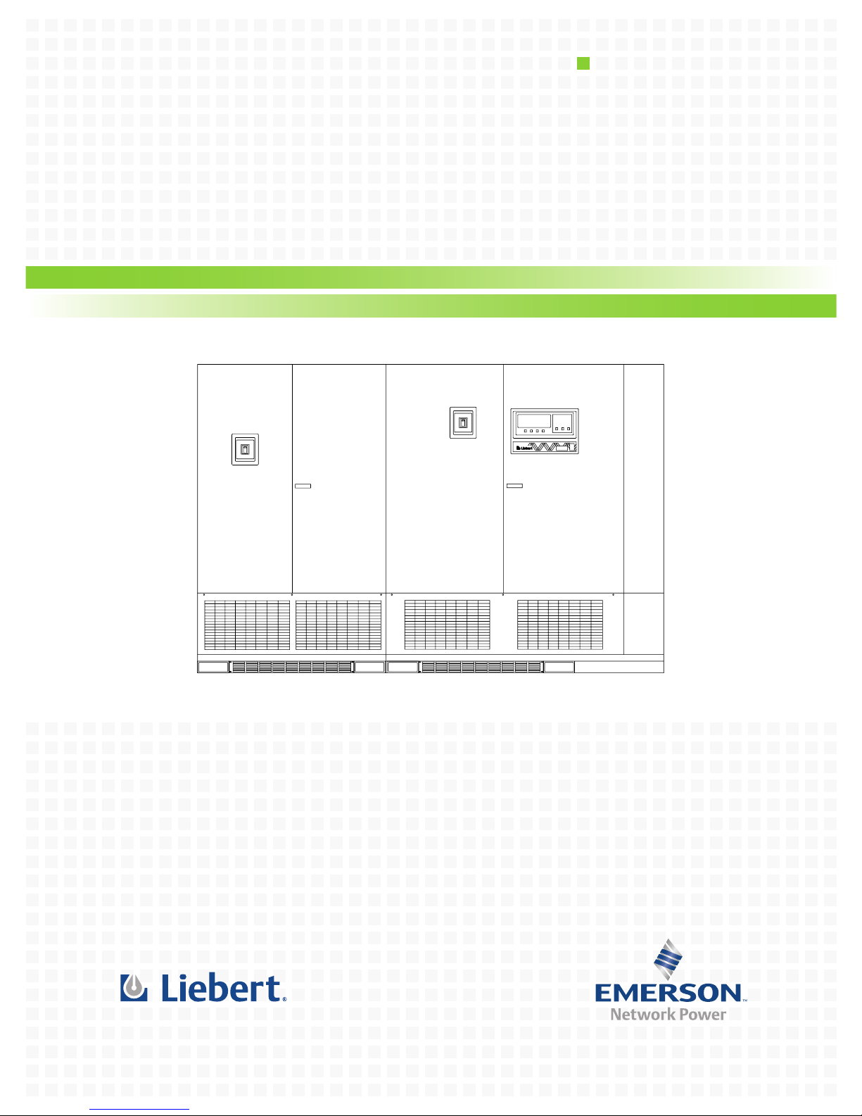
Liebert Series 610™ UPS
Installation Manual - 500-750kVA, 60Hz, Three Phase Multi-Module
AC Power
For Business-Critical Continuity™

BATTERY CABINET PRECAUTIONS
The following warning applies to all battery cabinets supplied with UPS systems. Additional
warnings and cautions applicable to battery cabinets may be found in:
• Important Safety Instructions—page 1
• Section 2.0 - Unloading and Handling
• Section 5.0 - Battery Installation
WARNING
!
Internal battery strapping must be verified by manufacturer prior to moving a battery cabinet
(after initial installation).
• Battery cabinets contain non-spillable batteries.
• Keep units upright.
• Do not stack.
• Do not tilt.
Failure to heed this warning could result in smoke, fire or electric hazard.
Call 1-800-LIEBERT prior to moving battery cabinets (after initial installation).
CONTACTING LIEBERT FOR SUPPORT
To contact Liebert Global Services for information or repair service in the United States, call
1-800-LIEBERT (1-800-543-2378). Liebert Global Services offers a complete range of start-up
services, repair services, preventive maintenance plans and service contracts.
For repair or maintenance service outside the 48 contiguous United States, contact Liebert Global
Services, if available in your area. For areas not covered by Liebert Global Services, the
authorized distributor is responsible for providing qualified, factory-authorized service.
For LGS to assist you promptly, please have the following information available:
Part numbers: _________________________________________________________________
Serial numbers:________________________________________________________________
Rating: _______________________________________________________________________
Date purchased: _______________________________________________________________
Date installed:_________________________________________________________________
Location:______________________________________________________________________
Input voltage/frequency:________________________________________________________
Output voltage/frequency: ______________________________________________________
Battery reserve time:___________________________________________________________

TABLE OF CONTENTS
BATTERY CABINET PRECAUTIONS . . . . . . . . . . . . . . . . . . . . . . . . . . . . . . . . . INSIDE FRONT COVER
CONTACTING LIEBERT FOR SUPPORT . . . . . . . . . . . . . . . . . . . . . . . . . . . . . . INSIDE FRONT COVER
IMPORTANT SAFETY INSTRUCTIONS . . . . . . . . . . . . . . . . . . . . . . . . . . . . . . . . . . . . . . . . . . . . . . . . 1
1.0 INSTALLATION CONSIDERATIONS. . . . . . . . . . . . . . . . . . . . . . . . . . . . . . . . . . . . . . . . . . . . .3
1.1 Types of System Control Cabinets. . . . . . . . . . . . . . . . . . . . . . . . . . . . . . . . . . . . . . . . . . . . . . . 5
2.0 UNLOADING AND HANDLING . . . . . . . . . . . . . . . . . . . . . . . . . . . . . . . . . . . . . . . . . . . . . . . . 6
3.0 INSPECTIONS . . . . . . . . . . . . . . . . . . . . . . . . . . . . . . . . . . . . . . . . . . . . . . . . . . . . . . . . . . . 7
3.1 External Inspections . . . . . . . . . . . . . . . . . . . . . . . . . . . . . . . . . . . . . . . . . . . . . . . . . . . . . . . . . 7
3.2 Internal Inspections and Shipping Material Removal. . . . . . . . . . . . . . . . . . . . . . . . . . . . . . . 7
4.0 EQUIPMENT LOCATION . . . . . . . . . . . . . . . . . . . . . . . . . . . . . . . . . . . . . . . . . . . . . . . . . . . .8
5.0 BATTERY INSTALLATION . . . . . . . . . . . . . . . . . . . . . . . . . . . . . . . . . . . . . . . . . . . . . . . . . . .9
5.1 Battery Safety Precautions . . . . . . . . . . . . . . . . . . . . . . . . . . . . . . . . . . . . . . . . . . . . . . . . . . . . 9
5.2 Battery Safety Precautions in French Per CSA Requirements . . . . . . . . . . . . . . . . . . . . . . . 10
5.3 Battery Cabinets. . . . . . . . . . . . . . . . . . . . . . . . . . . . . . . . . . . . . . . . . . . . . . . . . . . . . . . . . . . . 11
5.4 Open-Rack Batteries . . . . . . . . . . . . . . . . . . . . . . . . . . . . . . . . . . . . . . . . . . . . . . . . . . . . . . . . 12
6.0 CONFIGURING YOUR NEUTRAL AND GROUND CONNECTIONS . . . . . . . . . . . . . . . . . . . . . . .13
6.1 Preferred Grounding Configuration, Wye-Connected Service. . . . . . . . . . . . . . . . . . . . . . . . 14
6.2 Alternate Grounding Configuration, Wye-Connected Service. . . . . . . . . . . . . . . . . . . . . . . . 15
6.3 Preferred Grounding Configuration With Isolated Bypass . . . . . . . . . . . . . . . . . . . . . . . . . . 16
6.4 Alternate Grounding Configuration, Non-Isolated. . . . . . . . . . . . . . . . . . . . . . . . . . . . . . . . . 17
6.5 Grounding Configuration, Corner-Grounded Delta or Impedance-Grounded Wye . . . . . . . 18
6.6 Preferred Grounding Configuration, Battery Systems . . . . . . . . . . . . . . . . . . . . . . . . . . . . . 20
7.0 WIRING CONSIDERATIONS. . . . . . . . . . . . . . . . . . . . . . . . . . . . . . . . . . . . . . . . . . . . . . . . . 21
7.1 Power Wiring . . . . . . . . . . . . . . . . . . . . . . . . . . . . . . . . . . . . . . . . . . . . . . . . . . . . . . . . . . . . . . 22
7.2 Control Wiring . . . . . . . . . . . . . . . . . . . . . . . . . . . . . . . . . . . . . . . . . . . . . . . . . . . . . . . . . . . . . 24
7.3 Battery Wiring . . . . . . . . . . . . . . . . . . . . . . . . . . . . . . . . . . . . . . . . . . . . . . . . . . . . . . . . . . . . . 25
8.0 WIRING CONNECTIONS . . . . . . . . . . . . . . . . . . . . . . . . . . . . . . . . . . . . . . . . . . . . . . . . . . . 26
8.1 Specific Connections. . . . . . . . . . . . . . . . . . . . . . . . . . . . . . . . . . . . . . . . . . . . . . . . . . . . . . . . . 26
9.0 WIRING INSPECTION . . . . . . . . . . . . . . . . . . . . . . . . . . . . . . . . . . . . . . . . . . . . . . . . . . . . .28
10.0 INSTALLATION DRAWINGS. . . . . . . . . . . . . . . . . . . . . . . . . . . . . . . . . . . . . . . . . . . . . . . . . 31
A
PPENDIX A-SITE PLANNING DATA, SERIES 610, 500-750KVA, MULTI-MODULE SYSTEMS. . . . . 99
i

FIGURES
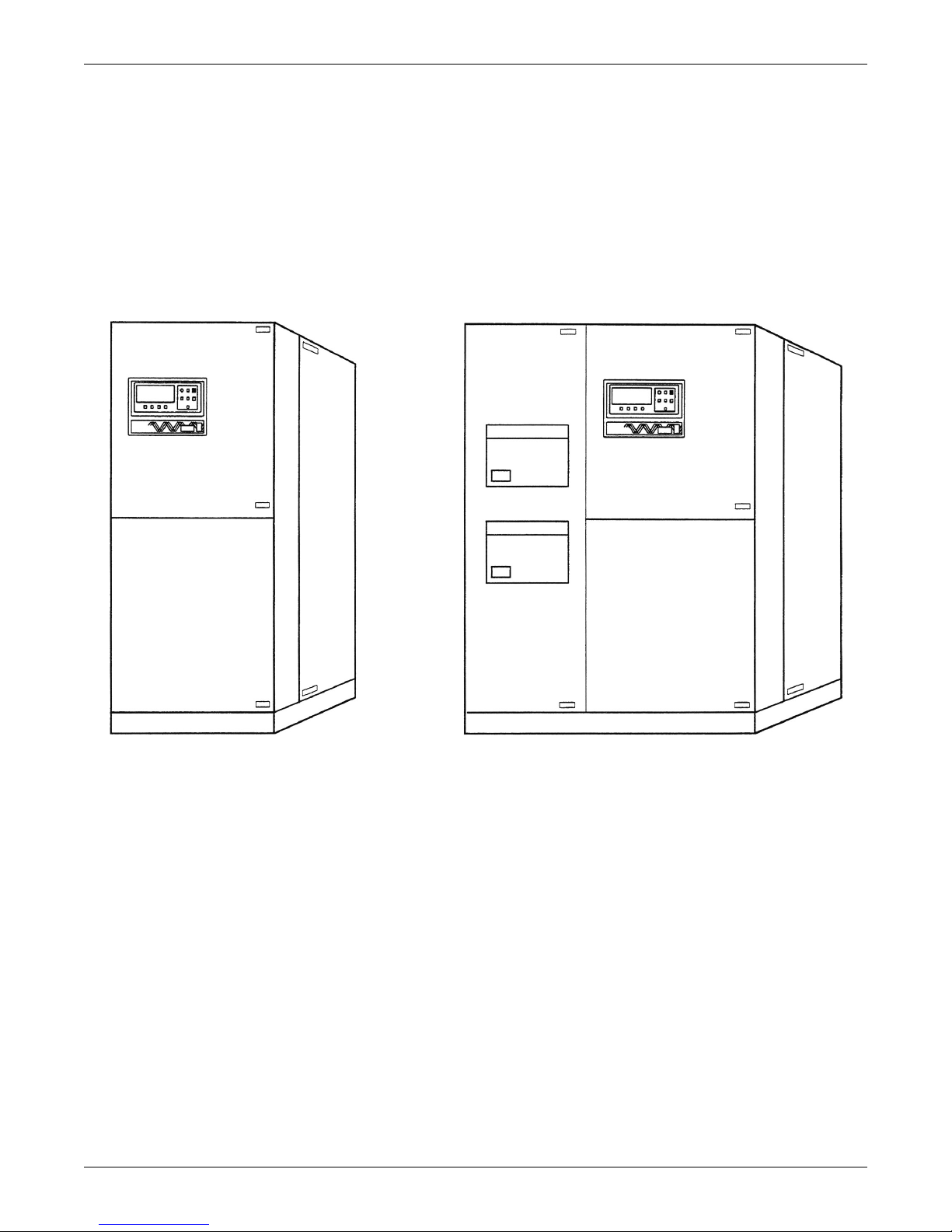
Figure 1 Multi-Module 500 to 750kVA UPS. . . . . . . . . . . . . . . . . . . . . . . . . . . . . . . . . . . . . . . . . . . . . . . . . . . 4
Figure 2 UPS Multi-Module Unit block diagram . . . . . . . . . . . . . . . . . . . . . . . . . . . . . . . . . . . . . . . . . . . . . . 4
Figure 3 System Control Cabinets . . . . . . . . . . . . . . . . . . . . . . . . . . . . . . . . . . . . . . . . . . . . . . . . . . . . . . . . . . 5
Figure 4 Preferred grounding configuration, wye-connected service . . . . . . . . . . . . . . . . . . . . . . . . . . . . . . 14
Figure 5 Alternate grounding configuration, wye-connected service . . . . . . . . . . . . . . . . . . . . . . . . . . . . . . 15
Figure 6 Preferred grounding configuration with isolated bypass . . . . . . . . . . . . . . . . . . . . . . . . . . . . . . . . 16
Figure 7 Alternate grounding configuration, non-isolated . . . . . . . . . . . . . . . . . . . . . . . . . . . . . . . . . . . . . . 17
Figure 8 Preferred grounding configuration, corner-grounded delta or impedance-grounded wye . . . . . . 18
Figure 9 Preferred grounding configuration, impedance-grounded wye . . . . . . . . . . . . . . . . . . . . . . . . . . . 19
Figure 10 Preferred grounding configuration, battery systems . . . . . . . . . . . . . . . . . . . . . . . . . . . . . . . . . . . 20
Figure 11 Power single line diagrams, Multi-Module configurations* . . . . . . . . . . . . . . . . . . . . . . . . . . . . . . 23
Figure 12 One-line diagram, two-module parallel system with two-breaker maintenance bypass . . . . . . . 31
Figure 13 One-line diagram, four-module parallel system with three-breaker maintenance bypass . . . . . 32
Figure 14 Outline drawing, 500kVA Multi-Module UPS, 6-pulse rectifier, 480V input, 480/277V
output. . . . . . . . . . . . . . . . . . . . . . . . . . . . . . . . . . . . . . . . . . . . . . . . . . . . . . . . . . . . . . . . . . . . . . . . . 33
Figure 15 Terminal details, 500kVA Multi-Module UPS, 6-pulse rectifier, 480V input, 480/277V
output. . . . . . . . . . . . . . . . . . . . . . . . . . . . . . . . . . . . . . . . . . . . . . . . . . . . . . . . . . . . . . . . . . . . . . . . . 34
Figure 16 Outline drawing, 500kVA Multi-Module UPS, 6-pulse rectifier, 600V input, 600/346V
output. . . . . . . . . . . . . . . . . . . . . . . . . . . . . . . . . . . . . . . . . . . . . . . . . . . . . . . . . . . . . . . . . . . . . . . . . 35
Figure 17 Terminal details, 500kVA Multi-Module UPS, 6-pulse rectifier, 600V input, 600/346V
output. . . . . . . . . . . . . . . . . . . . . . . . . . . . . . . . . . . . . . . . . . . . . . . . . . . . . . . . . . . . . . . . . . . . . . . . . 36
Figure 18 Outline drawing, 500kVA Multi-Module UPS, 12-pulse rectifier . . . . . . . . . . . . . . . . . . . . . . . . . 37
Figure 19 Terminal details, 500kVA Multi-Module UPS, 12-pulse rectifier . . . . . . . . . . . . . . . . . . . . . . . . . 38
Figure 20 Outline drawing, 625-750kVA Multi-Module UPS, 6-pulse rectifier. . . . . . . . . . . . . . . . . . . . . . . 39
Figure 21 Terminal details, 625-750kVA Multi-Module UPS, 6-pulse rectifier. . . . . . . . . . . . . . . . . . . . . . . 40
Figure 22 Outline drawing, 625-750kVA Multi-Module UPS, 12-pulse rectifier. . . . . . . . . . . . . . . . . . . . . . 41
Figure 23 Terminal details, 625-750kVA Multi-Module UPS, 12-pulse rectifier. . . . . . . . . . . . . . . . . . . . . . 42
Figure 24 Outline drawing, 500kVA Multi-Module UPS, 12-pulse rectifier with bottom entry
wireway . . . . . . . . . . . . . . . . . . . . . . . . . . . . . . . . . . . . . . . . . . . . . . . . . . . . . . . . . . . . . . . . . . . . . . . 43
Figure 25 Terminal details, 500kVA Multi-Module UPS, 12-pulse rectifier with bottom entry
wireway . . . . . . . . . . . . . . . . . . . . . . . . . . . . . . . . . . . . . . . . . . . . . . . . . . . . . . . . . . . . . . . . . . . . . . . 44
Figure 26 Outline drawing, 625-750kVA Multi-Module UPS, 6-pulse rectifier with bottom entry
wireway . . . . . . . . . . . . . . . . . . . . . . . . . . . . . . . . . . . . . . . . . . . . . . . . . . . . . . . . . . . . . . . . . . . . . . . 45
Figure 27 Terminal details, 625-750kVA Multi-Module UPS, 6-pulse rectifier with bottom entry
wireway . . . . . . . . . . . . . . . . . . . . . . . . . . . . . . . . . . . . . . . . . . . . . . . . . . . . . . . . . . . . . . . . . . . . . . . 46
Figure 28 Outline drawing, 625-750kVA Multi-Module UPS, 12-pulse rectifier with bottom entry
wireway . . . . . . . . . . . . . . . . . . . . . . . . . . . . . . . . . . . . . . . . . . . . . . . . . . . . . . . . . . . . . . . . . . . . . . . 47
Figure 29 Terminal details, 625-750kVA Multi-Module UPS, 12-pulse rectifier with bottom entry
wireway . . . . . . . . . . . . . . . . . . . . . . . . . . . . . . . . . . . . . . . . . . . . . . . . . . . . . . . . . . . . . . . . . . . . . . . 48
Figure 30 Terminal details, 750kVA/675kW Multi-Module UPS, 12-pulse rectifier with bottom entry
wireway . . . . . . . . . . . . . . . . . . . . . . . . . . . . . . . . . . . . . . . . . . . . . . . . . . . . . . . . . . . . . . . . . . . . . . . 49
Figure 31 Base mounting patterns, 500kVA module, 6-pulse rectifier. . . . . . . . . . . . . . . . . . . . . . . . . . . . . . 50
Figure 32 Base mounting patterns, 500kVA module, 12-pulse rectifier. . . . . . . . . . . . . . . . . . . . . . . . . . . . . 51
Figure 33 Base mounting patterns, 500kVA module, 12-pulse rectifier with bottom entry wireway . . . . . 52
Figure 34 Base mounting patterns, 625-750kVA module, 6-pulse rectifier . . . . . . . . . . . . . . . . . . . . . . . . . . 53
Figure 35 Base mounting patterns, 625-750kVA module, 6-pulse rectifier with bottom entry wireway . . . 54
Figure 36 Base mounting patterns, 625-750kVA module, 12-pulse rectifier . . . . . . . . . . . . . . . . . . . . . . . . . 55
Figure 37 Base mounting patterns, 625-750kVA module, 12-pulse rectifier with bottom entry wireway . . 56
Figure 38 Shipping split detail, 500kVA, 12-pulse rectifier . . . . . . . . . . . . . . . . . . . . . . . . . . . . . . . . . . . . . . 57
Figure 39 Shipping split detail, 500kVA, 12-pulse rectifier with bottom entry wireway . . . . . . . . . . . . . . . 58
Figure 40 Shipping split detail, 625-750kVA, 6-pulse rectifier. . . . . . . . . . . . . . . . . . . . . . . . . . . . . . . . . . . . 59
Figure 41 Shipping split detail, 625-750kVA, 6-pulse rectifier with bottom entry wireway. . . . . . . . . . . . . 60
Figure 42 Shipping split detail, 625-750kVA, 12-pulse rectifier. . . . . . . . . . . . . . . . . . . . . . . . . . . . . . . . . . . 61
ii

Figure 43 Shipping split detail, 625-750kVA, 12-pulse rectifier with bottom entry wireway. . . . . . . . . . . . 62
Figure 44 Battery power pack system . . . . . . . . . . . . . . . . . . . . . . . . . . . . . . . . . . . . . . . . . . . . . . . . . . . . . . . 63
Figure 45 Battery power pack, Size A. . . . . . . . . . . . . . . . . . . . . . . . . . . . . . . . . . . . . . . . . . . . . . . . . . . . . . . . 64
Figure 46 Line-up detail, 300-500kVA Single- or Multi-Module System with battery cabinets . . . . . . . . . . 65
Figure 47 Outline drawing, System Control Cabinet (SCCT), 200-1200A . . . . . . . . . . . . . . . . . . . . . . . . . . . 66
Figure 48 Base mounting patterns, System Control Cabinet (SCCT), 200-1200A . . . . . . . . . . . . . . . . . . . . 67
Figure 49 Outline drawing, System Control Cabinet (SCCT), 1600-2000A . . . . . . . . . . . . . . . . . . . . . . . . . . 68
Figure 50 Base mounting patterns, System Control Cabinet (SCCT), 1600-2000A . . . . . . . . . . . . . . . . . . . 69
Figure 51 Outline drawing, System Control Cabinet (SCCT), 2500-3000A . . . . . . . . . . . . . . . . . . . . . . . . . . 70
Figure 52 Base mounting patterns, System Control Cabinet (SCCT), 2500-3000A . . . . . . . . . . . . . . . . . . . 71
Figure 53 Outline drawing, System Control Cabinet (SCCT), 4000A . . . . . . . . . . . . . . . . . . . . . . . . . . . . . . 72
Figure 54 Base mounting patterns, System Control Cabinet (SCCT), 4000A . . . . . . . . . . . . . . . . . . . . . . . . 73
Figure 55 Control connection location diagram, Multi-Module System, 300-500kVA. . . . . . . . . . . . . . . . . . 74
Figure 56 Control connection location diagram, Multi-Module System, 625 & 750kVA . . . . . . . . . . . . . . . . 75
Figure 57 Control connection location diagram, SCCT . . . . . . . . . . . . . . . . . . . . . . . . . . . . . . . . . . . . . . . . . . 76
Figure 58 Control wiring, external interconnect diagram, Multi-Module System. . . . . . . . . . . . . . . . . . . . . 77
Figure 59 Control wire list, external interconnections, standard wiring, Multi-Module System,
UPS module, Cable Group #1. . . . . . . . . . . . . . . . . . . . . . . . . . . . . . . . . . . . . . . . . . . . . . . . . . . . . . 78
Figure 60 Control wire list, external interconnections, standard wiring, Multi-Module System,
System Control Cabinet, Part 1 of 3, Cable Groups #2 & #3 . . . . . . . . . . . . . . . . . . . . . . . . . . . . . 79
Figure 61 Control wire list, external interconnections, standard wiring, Multi-Module System,
System Control Cabinet, Part 2 of 3, Cable Groups #5 & #6 . . . . . . . . . . . . . . . . . . . . . . . . . . . . . 80
Figure 62 Control wire list, external interconnections, standard wiring, Multi-Module System,
System Control Cabinet, Part 3 of 3, Cable Group #8 . . . . . . . . . . . . . . . . . . . . . . . . . . . . . . . . . . 81
Figure 63 Control wire list, external interconnections, Multi-Module System, remote status panel
option, Cable Group #4 . . . . . . . . . . . . . . . . . . . . . . . . . . . . . . . . . . . . . . . . . . . . . . . . . . . . . . . . . . . 82
Figure 64 Control wire list, external interconnections, Multi-Module System (SCC with momentary
duty static switch), customer alarm interface option, Cable Group #9 . . . . . . . . . . . . . . . . . . . . . 83
Figure 65 Control wire list, external interconnections, Multi-Module System, alarm status contacts
option, Cable Group #14 . . . . . . . . . . . . . . . . . . . . . . . . . . . . . . . . . . . . . . . . . . . . . . . . . . . . . . . . . . 84
Figure 66 Control wire list, external interconnections, Multi-Module System, battery temperature
sensor option, Cable Group #15 . . . . . . . . . . . . . . . . . . . . . . . . . . . . . . . . . . . . . . . . . . . . . . . . . . . . 85
Figure 67 Control wire list, external interconnections, Multi-Module System, maintenance bypass
interlock option, Cable Group #7 . . . . . . . . . . . . . . . . . . . . . . . . . . . . . . . . . . . . . . . . . . . . . . . . . . . 86
Figure 68 Control wire list, external interconnections, Multi-Module System, SNMP interface option,
Cable Group #26 . . . . . . . . . . . . . . . . . . . . . . . . . . . . . . . . . . . . . . . . . . . . . . . . . . . . . . . . . . . . . . . . 87
Figure 69 Control wire list, external interconnections, Multi-Module System, Module 1/SCC,
Cable Groups #20 & #21 . . . . . . . . . . . . . . . . . . . . . . . . . . . . . . . . . . . . . . . . . . . . . . . . . . . . . . . . . . 88
Figure 70 Control wire list, external interconnections, Multi-Module System, Module 2/SCC,
Cable Groups #20 & #21 . . . . . . . . . . . . . . . . . . . . . . . . . . . . . . . . . . . . . . . . . . . . . . . . . . . . . . . . . . 89
Figure 71 Control wire list, external interconnections, Multi-Module System, Module 3/SCC,
Cable Groups #20 & #21 . . . . . . . . . . . . . . . . . . . . . . . . . . . . . . . . . . . . . . . . . . . . . . . . . . . . . . . . . . 90
Figure 72 Control wire list, external interconnections, Multi-Module System, Module 4/SCC,
Cable Groups #20 & #21 . . . . . . . . . . . . . . . . . . . . . . . . . . . . . . . . . . . . . . . . . . . . . . . . . . . . . . . . . . 91
Figure 73 Control wire list, external interconnections, Multi-Module System, Module 5/SCC,
Cable Groups #20 & #21 . . . . . . . . . . . . . . . . . . . . . . . . . . . . . . . . . . . . . . . . . . . . . . . . . . . . . . . . . . 92
Figure 74 Control wire list, external interconnections, Multi-Module System, Module 6/SCC,
Cable Groups #20 & #21 . . . . . . . . . . . . . . . . . . . . . . . . . . . . . . . . . . . . . . . . . . . . . . . . . . . . . . . . . . 93
Figure 75 Outline drawing, single-breaker module battery disconnect,
300, 450, 600, 800, 1000, 1200A . . . . . . . . . . . . . . . . . . . . . . . . . . . . . . . . . . . . . . . . . . . . . . . . . . . . 94
Figure 76 Outline drawing, single-breaker module battery disconnect,
1400AT/1600AT/2000AT/2500AT 600VDC circuit breaker . . . . . . . . . . . . . . . . . . . . . . . . . . . . . . 95
Figure 77 Outline drawing, dual-breaker module battery disconnect, 600, 800, 1000, 1200A . . . . . . . . . . . 96
Figure 78 Outline drawing, remote status panel, surface mount . . . . . . . . . . . . . . . . . . . . . . . . . . . . . . . . . . 97
iii

TABLES
Table 1 Abbreviations for circuit breakers . . . . . . . . . . . . . . . . . . . . . . . . . . . . . . . . . . . . . . . . . . . . . . . . . . 24
Table 2 Power wiring terminals, factory supplied . . . . . . . . . . . . . . . . . . . . . . . . . . . . . . . . . . . . . . . . . . . . 28
Table 3 Torque specifications . . . . . . . . . . . . . . . . . . . . . . . . . . . . . . . . . . . . . . . . . . . . . . . . . . . . . . . . . . . . 28
Table 4 Field-supplied lugs . . . . . . . . . . . . . . . . . . . . . . . . . . . . . . . . . . . . . . . . . . . . . . . . . . . . . . . . . . . . . . 29
Table 5 Table 310-16, National Electrical Code (Reprint) . . . . . . . . . . . . . . . . . . . . . . . . . . . . . . . . . . . . . . 30
Table 6 Site planning data—600V input. . . . . . . . . . . . . . . . . . . . . . . . . . . . . . . . . . . . . . . . . . . . . . . . . . . 100
Table 7 Site planning data—480V input. . . . . . . . . . . . . . . . . . . . . . . . . . . . . . . . . . . . . . . . . . . . . . . . . . . 101
Table 8 System Control Cabinet data - SCCT . . . . . . . . . . . . . . . . . . . . . . . . . . . . . . . . . . . . . . . . . . . . . . 102
iv
IMPORTANT SAFETY INSTRUCTIONS
SAVE THESE INSTRUCTIONS
This manual contains important instructions that should be followed during installation of your
Series 610 UPS and batteries.
WARNING
!
Exercise extreme care when handling UPS cabinets to avoid equipment damage or injury to
personnel. The UPS module weight ranges from 5710 to 12,005 lbs. (2590 to 5445kg),
including input transformer. The battery cabinets weigh from 3060 to 5300 lbs. (1388 to
2404kg).
Locate center of gravity symbols and determine unit weight before handling each
cabinet. Test lift and balance the cabinets before transporting. Maintain minimum tilt from
vertical at all times.
Slots at the base of the modules and battery cabinets are intended for forklift use. Base slots
will support the unit only if the forks are completely beneath the unit.
System Control Cabinets (SCCs) have holes intended for rigging bars or chains. Prevent
chains or cables from contacting cabinet by using spreader bar and adequate padding.
Follow all battery safety precautions when installing, charging or servicing batteries. In
addition to the hazard of electric shock, gas produced by batteries can be explosive and
sulfuric acid can cause severe burns.
In case of fire involving electrical equipment, use only carbon dioxide fire extinguishers or
those approved for use in fighting electrical fires.
Extreme caution is required when performing maintenance.
Be constantly aware that the UPS system contains high DC as well as AC voltages.
Check for voltage with both AC and DC voltmeters prior to making contact.
Read this manual thoroughly, paying special attention to the sections that apply to your installation,
before working with the UPS. Retain this manual for use by installing personnel.
WARNING
!
Under typical operation and with all UPS doors closed, only normal safety precautions are
necessary. The area around the UPS system should be kept free of puddles of water, excess
moisture and debris.
Special safety precautions are required for procedures involving handling, installation and
maintenance of the UPS system and the battery. Observe all safety precautions in this
manual before handling or installing the UPS system. Observe all precautions in the
Operation and Maintenance Manual, before as well as during performance of all maintenance
procedures. Observe all battery safety precautions before working on or near the battery.
This equipment contains several circuits that are energized with high voltage. Only
test equipment designed for troubleshooting should be used. This is particularly true for
oscilloscopes. Always check with an AC and DC voltmeter to ensure safety before making
contact or using tools. Even when the power is turned Off, dangerously high potential electric
charges may exist at the capacitor banks and at the batteries.
All power and control wiring should be installed by a qualified electrician. All power
and control wiring must comply with the NEC and applicable local codes.
ONLY qualified service personnel should perform maintenance on the UPS system.
When performing maintenance with any part of the equipment under power, service
personnel and test equipment should be standing on rubber mats. The service personnel
should wear insulating shoes for isolation from direct contact with the floor (earth ground).
One person should never work alone, even if all power is removed from the equipment. A second
person should be standing by to assist and summon help in case an accident should occur.
1

CAUTION
!
This unit complies with the limits for a Class A digital device, pursuant to Part 15 Subpart J
of the FCC rules and EN550022. These limits provide reasonable protection against harmful
interference in a commercial environment. This unit generates, uses and radiates radio
frequency energy and, if not installed and used in accordance with this instruction manual,
may cause harmful interference to radio communications. Operation of this unit in a
residential area may cause harmful interference that the user must correct at his own
expense.
NOTE
Liebert Corporation neither recommends nor knowingly sells this product for use with life
support or other FDA-designated “critical” devices.
2
1.0 INSTALLATION CONSIDERATIONS
Install your Series 610 UPS in accordance with the submittal drawing package and the following procedures.
A Liebert authorized representative must perform the initial system check-out and start-up to ensure
proper system operation. Equipment warranties will be voided unless system start-up is performed by
a Liebert authorized representative. Contact your local Liebert sales representative or Liebert Global
Services at 1-800-LIEBERT to arrange for system start-up.
CAUTION
!
Read this manual thoroughly before attempting to wire or operate the unit. Improper
installation is the most significant cause of UPS start-up problems.
Do not install this equipment near gas or electric heaters. It is preferable to install the UPS in
a restricted location to prevent access by unauthorized personnel.
1. Proper planning will speed unloading, location and connection of the UPS. Refer to Figures 13
through 78 and Appendix A.
2. Be certain that the floor at the final equipment location and along the route (inside the facility) to
the installation site can support the cabinet weight and the weight of any moving equipment. The
modules weigh from 5710 to 12,005 lbs. (2590 to 5445kg). The battery cabinets weigh from 3060 to
5300 lbs. (1388 to 2404kg). The System Control Cabinets weigh from 1000 to 5850 lbs. (454 to
2653kg). Refer to Appendix A. For switchgear weights, refer to your submittal package.
WARNING
!
Locate center of gravity symbols and determine unit weight before handling cabinet.
3. Plan the route to ensure that the unit can move through all aisleways and doorways and around
corners without risking damage. If the modules and batteries must be moved by elevator, check
the size of the door openings and the weight-carrying capacity of the elevator.
4. Refer to information later in this manual regarding the optional battery cabinets and
Transformer Cabinets. Observe all battery safety precautions when working on or near
the battery.
5. Use the shortest output distribution cable runs possible, consistent with logical equipment
arrangements and with allowances for future additions if planned.
6. Recommended ambient operating temperature is 77°F (25°C). Relative humidity must be less
than 95%, non-condensing. Note that room ventilation is necessary, but air conditioning may not
be required. Maximum ambient operating temperature is 104°F (40°C) without derating. The
batteries should not exceed 77°F (25°C). At elevations above 4000 ft. (1219m), temperature
derating may be required for full power output—consult your Liebert sales representative or call
1-800-LIEBERT.
7. Even though your Liebert UPS unit is at least 92-94% efficient, the heat output is substantial. For
more specific information, see Appendix A. Be sure environmental conditioning systems can
accommodate this BTU load, even during utility outages.
8. The installer should attempt to balance the load between the three output phases. The UPS will
operate safely with an unbalanced load, but will give optimum performance if the three output
phases are loaded within 20 percent of each other.
9. During normal UPS operations, short-term overload current demand from the bypass source may
reach 10x the UPS output current rating. This overload current demand may be caused by the
magnetizing inrush current of one or more downstream transformers or faults on downstream
branch circuits. The instantaneous trip point(s) of the upstream bypass feeder breaker(s) must be
set to support these temporary overloads. The magnitude of short-term overload bypass current
demand is typically six to eight times the UPS current rating, but must be determined by analysis
on a per-site basis. This analysis, generally known as an End-to-End Fault Coordination Study,
must be done by a Registered Professional Engineer experienced in this activity and familiar with
local codes and related requirements.
Installation Considerations
NOTE
While Liebert can provide typical guidelines, the responsibility for the proper breaker trip
settings outside of the Liebert-manufactured UPS equipment resides with the owner. Contact
Liebert Global Services at 1-800-LIEBERT for further details.
3
10. A breaker coordination study should be performed to ensure proper handling of fault currents.
NOTE
The instantaneous trip setting of the breaker feeding the SCC bypass input should be high
enough to accommodate short-duration overloads. The bypass static switch inside the SCC can
draw up to 10 times the system’s rated current for up to three cycles.
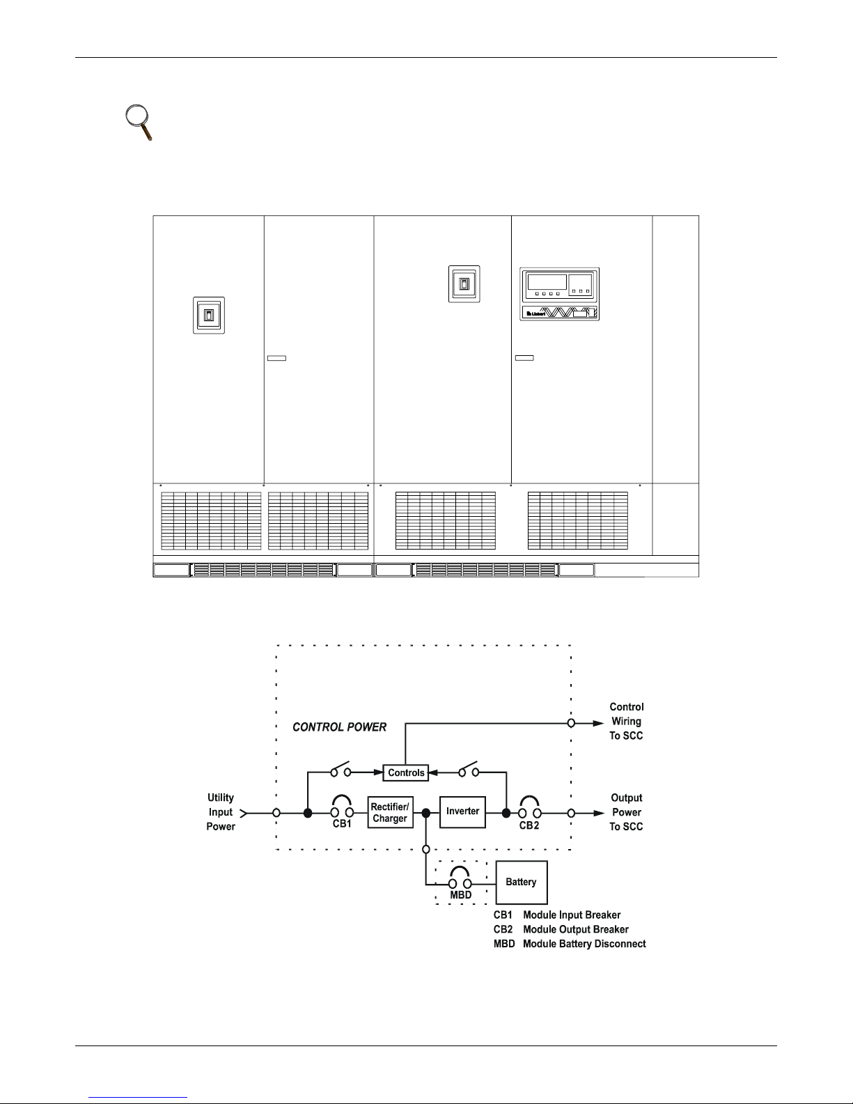
Figure 1 Multi-Module 500 to 750kVA UPS
Installation Considerations
Figure 2 UPS Multi-Module Unit block diagram
UPS MODULE
4
1.1 Types of System Control Cabinets
1. SCCT is a stand-alone cabinet containing system control logic for up to six UPS modules, static
bypass switch, manually operated disconnects for the static bypass switch, and two motoroperated system breakers. The SCCT is painted the same color as the Liebert UPS, but does not
match the sheet metal style of the UPS. For SCCT dimensions, refer to Table 8.
2. SCCI has the system control logic, circuit breakers and static bypass switch integrated into a
switchboard cabinet manufactured by others.
3. SCCC is an integrated configuration like the SCCI with the static bypass switch rated for
continuous duty.
Figure 3 System Control Cabinets
Installation Considerations
5
2.0 UNLOADING AND HANDLING
With the exception of the 500kVA unit with 6-pulse rectifier, UPS modules are shipped in split cabinets to allow ease of handling. Because the weight distribution in the cabinets is uneven, use extreme
care during handling and transport. Your installation may also include battery cabinets and a System
Control Cabinet.
NOTE
It is very important that the shipping split sections are matched up to their proper mates, as
identified by the shipping split labels.
Integrated SCC/Switchgear will also be shipped in sections, and require proper match up of
sections, as identified by labels and drawings.
WARNING
!
Exercise extreme care when handling UPS cabinets to avoid equipment damage or injury to
personnel. The UPS module weight ranges from 5710 to 12,005 lbs. (2590 to 5445kg). Battery
cabinets weigh from 3060 to 5300 lbs. (1388 to 2404kg).
Locate center of gravity symbols before handling cabinet. Test lift and balance the cabinet
before transporting. Maintain minimum tilt from vertical at all times.
Slots at the base of the modules and battery cabinets are intended for forklift use. Base slots
will support the unit only if the forks are completely beneath the unit.
Unloading and Handling
System Control Cabinets (SCCs)/Switchgear have holes intended for rigging bars or chains
(see your submittal package for switchgear drawings). Prevent chains or cables from
contacting cabinet by using spreader bar and adequate padding.
To reduce the possibility of shipping damage, cabinets are shored with 2-by-4 bracing, secured with
screw-type nails. This shoring must be carefully removed prior to unloading.
CAUTION
!
Extreme care is necessary when removing shoring braces. Do not strike cabinet with
hammers or other tools.
6

3.0 INSPECTIONS
3.1 External Inspections
1. While the UPS system is still on the truck, inspect the equipment and shipping container(s) for
any signs of damage or mishandling. Do not attempt to install the system if damage is apparent.
If any damage is noted, file a damage claim with the shipping agency within 24 hours and contact
Liebert Global Services at 1-800-LIEBERT to inform them of the damage claim and the condition
of the equipment.
2. Compare the contents of the shipment with the bill of lading. Report any missing items to the
carrier and to Liebert Global Services immediately.
3. Remove equipment from truck using appropriate handling precautions and equipment.
4. Each shipping section will be identified by a label located on the plywood piece that is used to
cover the end sections of each shipping split, or on the pallet that the equipment is shipped on.
Before removing wood shipping covers, identify the individual pieces and group together the
shipping sections of each individual UPS module.
5. Locate cabinet keys. Depending upon equipment type, the keys will either reside in a plastic bag
marked “Packing slip enclosed” on a front door of the cabinet, or be taped to a circuit breaker
handle protruding through the front of the cabinet.
3.2 Internal Inspections and Shipping Material Removal
1. Verify that all items have been received.
2. If spare parts were ordered, verify arrival.
3. Open doors and remove cabinet panels to check for shipping damage to internal components.
4. Check for loose connections or unsecured components in the cabinet(s).
5. Check for installation of circuit breaker line safety shields. There should be no exposed circuit
breaker terminals when the cabinet doors are opened.
6. Check for any unsafe condition that may be a potential safety hazard.
7. UPS modules are shipped with internally mounted shipping brackets. The shipping brackets
(painted orange) must be removed from the rear (remove rear panels). The installer must remove
the orange shipping brackets before final equipment placement, particularly if rear access will be
restricted.
Inspections
CAUTION
!
Failure to remove orange shipping brackets from transformers may cause restricted airflow
within the UPS. This could cause overheating or reduction of UPS capacity. In some cases, it
could cause damage to the UPS module, and such damage would not be covered under the
factory warranty. If you foresee a situation where the UPS will be relocated in the near
future, the brackets should be removed and stored elsewhere until they are needed.
8. Remove wood shipping split covers. These covers consist of a 2-by-4 frame covered with plywood.
The 2-by-4 frame is attached using lag bolts screwed into the wood from the inside of the cabinet.
9. Check the nameplate/ratings label on the inside of the Module and SCC control section doors to
verify that the model numbers correspond with those specified. Record the model numbers and
serial numbers in the front of this installation manual. A record of this information is necessary
should servicing be required.
7

4.0 EQUIPMENT LOCATION
1. Handle cabinet(s) in accordance with the safety precautions in this manual, especially in these
sections:
• Battery Cabinet Precautions—inside front cover
• Important Safety Instructions—page 1
• 2.0 - Unloading and Handling—page 6
• 5.0 - Battery Installation—page 9
Use a suitable material handling device to move the cabinet to its final location. Exercise
extreme care because of the uneven weight distribution. Carefully lower the cabinet to the
floor.
2. Referring to Shipping Split Detail (Figures 38 through 43), and any other drawings that are
associated with switchgear, set cabinets in final position, preparatory to reconnection of shipping
split power and control wiring/bus.
3. Verify that the UPS system is installed in a clean, cool and dry location.
4. Installation and serviceability will be easier if adequate access is provided on all sides of the
equipment, but only front access is required.
a. Verify that there is adequate clearance to open cabinet doors—4 ft. (1.2m) is recommended.
NEC requires sufficient clearance in front of the equipment to fully open all doors without
restriction. See drawings and local codes. SCCT requires front and rear or one-side access for
installation and maintenance.
b. Verify that there is adequate area in front of circuit breakers to perform maintenance. Check
installation drawings for location of breakers. Check with local codes.
c. Verify that there is adequate clearance above all cabinets to allow exhaust air to flow without
restriction. The minimum clearance is 2 ft. (0.6m), unobstructed by conduit or any other
items. Liebert recommends against using upflow air conditioning systems or any system that
blows air down onto the top of the modules.
5. Align the UPS cabinet, battery cabinets (if used) and optional transformer and maintenance
bypass cabinets, as shown in the Line-Up Detail drawing (Figure 46) and your submittal
package.
6. Referring to Shipping Split Details (Figures 38 through 43 and your submittal package for SCC/
Switchgear drawings), connect cabinets together mechanically.
7. Referring to Shipping Split Details (Figures 38 through 43 and your submittal package for SCC/
Switchgear drawings), connect intercabinet ground straps, power wiring and bus interconnects.
Internal control connections should be left disconnected for later installation by Liebert LGS
Customer Engineers.
Equipment Location
8

5.0 BATTERY INSTALLATION
5.1 Battery Safety Precautions
Servicing of batteries should be performed or supervised by personnel knowledgeable of batteries and
the required precautions. Keep unauthorized personnel away from batteries.
When replacing batteries, use the same number and type of batteries.
CAUTION
!
Lead-acid batteries contain hazardous materials. Batteries must be handled, transported and
recycled or discarded in accordance with federal, state and local regulations. Because lead is a
toxic substance, lead-acid batteries must be recycled rather than discarded.
Do not open or mutilate the battery or batteries. Released electrolyte is harmful to the skin
and eyes. It is toxic. Do not dispose of battery or batteries in a fire. The battery may explode.
Do not install any batteries that are cracked, leaking or show other signs of damage. Contact
Liebert Global Services or your local Liebert representative.
A battery can present a risk of electrical shock and high short circuit current. The following
precautions should be observed when working on batteries:
• Remove watches, rings and other metal objects.
• Use tools with insulated handles.
• Wear rubber gloves and boots.
• Do not lay tools or metal parts on top of batteries.
• Disconnect charging source prior to connecting or disconnecting battery terminals.
• Determine if battery is inadvertently grounded. If inadvertently grounded, remove source
of ground. Contact with any part of a grounded battery can result in electrical shock. The
likelihood of such shock will be reduced if such grounds are removed during installation
and maintenance.
Lead-acid batteries can present a risk of fire because they generate hydrogen gas. The
following procedures should be followed:
Battery Installation
• DO NOT SMOKE when near batteries.
• DO NOT cause flame or spark in battery area.
• Discharge static electricity from body before touching batteries by first touching a grounded
metal surface.
• After replacing battery jars in a battery cabinet, replace the retaining straps that hold the
jars in place on the shelves. This will limit accidental movement of the jars and connectors
should the cabinet ever need to be repositioned or relocated. Regular maintenance of the
battery module is an absolute necessity. Periodic inspections of battery and terminal voltages, specific gravity and connection resistance should be made. Strictly follow the procedures outlined in the battery manufacturer’s manual, available on the manufacturer’s Web
site.
9

5.2 Battery Safety Precautions in French Per CSA Requirements
Instructions Importantes Concernant La Sécurité
Conserver Ces Instructions
AVERTISSEMENT
!
Respecter toutes les consignes de sécurité applicables à l'installation, le chargement ou
l'entretien des batteries. En plus du danger de chocs électriques, le gaz produit par les
batteries peut exploser dégageant de l'acide sulfurique qui peut entraîner de très graves
brûlures.
Toute opération d'entretien/réparation des batteries doit être exécutée ou supervisée par un
personnel qualifié dans le domaine et en prenant toutes les précautions nécessaires. Tenir le
personnel non autorisé à l’écart des batteries.
ATTENTION
!
Les batteries acide-plomb contiennent des substances toxiques dangereuses. Les batteries
doivent être manipulées, transportées et recyclées ou jetées conformément à la
réglementation en vigueur aux niveaux national et local. Le plomb étant toxique, les batteries
acide-plomb doivent être recyclées et non jetées.
Ne pas ouvrir ni endommager la ou les batteries. Les électrolytes diffusés sont dangereux
pour la peau et les yeux. Ils sont toxiques. Ne pas jeter la ou les batteries dans le feu. Risque
d'explosion.
Ne jamais installer de batteries avec des cellules fissurées ou endommagées. Contacter
Liebert Global Services ou le représentant agréé Liebert local.
Une batterie peut poser un risque de choc électrique et de courant élevé provoqué par un
court-circuit. Respecter les précautions suivantes lors de travaux sur les batteries:
• Enlever montres, bagues ou autres objets métalliques.
• Utiliser des outils dont les poignées sont isolées.
• Porter des gants et des bottes en caoutchouc.
• Ne pas poser d'outils ou d'objets métalliques sur les batteries.
• Déconnecter la source de chargement avant de connecter ou de déconnecter les bornes de
batterie.
• Vérifier que la batterie n'a pas été mise à la masse par inadvertance. Si elle est mise à la
masse, éliminer la source de masse. Tout contact avec des composants de batterie mise à la
masse peut entraîner un choc électrique. Éliminer le risque de chocs électriques potentiels
en retirant les sources de masse avant l'installation et la maintenance.
Les batteries acide-plomb peuvent représenter un risque d'incendie puisqu'elles génèrent de
l'hydrogène. Respecter les procédures suivantes:
• NE PAS FUMER près des batteries.
• NE PAS générer de flammes ou d'étincelles près des batteries.
• Éliminer l'électricité statique du corps avant de manipuler les batteries en touchant d'abord
une surface métallique mise à la terre.
L’électrolyte est un acide sulfurique dilué qui est dangereux au contact de la peau et des yeux.
Ce produit est corrosif et aussi conducteur electrique. Les procédures suivantes devront être
observées:
• Porter toujours des vêtements protecteurs ainsi que des lunettes de protection pour les yeux.
• Si l’électrolyte entre en contact avec la peau, nettoyer immédiatement en rincant avec de l’eau.
• Si l’électrolyte entre en contact avec les yeux, arroser immédiatement et généreusement
avec de l’eau. Demander pour de l’aide médicale.
• Lorsque l’électrolyte est renversée, la surface affectée devrait être nettoyée en utilisant un
agent neutralisant adéquat. Une pratique courante est d’utiliser un mélange d’approximativement une livre (500 grammes) de bicarbonate de soude dans approximativement un gallon (4 litres) d’eau. Le mélange de bicarbonate de soude devra être ajouté jusqu’à ce qu’il n’y
ait plus apparence de réaction (mousse). Le liquide résiduel devra être nettoyé à l’eau et la
surface concernée devra être asséchée.
Battery Installation
10

5.3 Battery Cabinets
Optional battery cabinets are available from Liebert and other qualified vendors. Consult your submittal package for details.
Several models of optional battery cabinets with varying run times are available. Each model is 78"
(1981mm) high and has forklift slots. Refer to Figures 44 through 46. The battery cabinet cells range
from 90 to 150 ampere-hours. The same model battery cabinet may be paralleled in multiple cabinet
strings for additional capacity. Battery capacity (in minutes) at your installation will depend on cabinet model, number of cabinets and amount of critical load on the UPS.
1. Handling. The battery cabinet weighs from 3060 to 5300 lbs. (1388 to 2404kg). Forklift slots are
provided for ease of handling.
2. Cabinet Inspection. Remove all panels and visually inspect the batteries, bus connections, and
cabinet for any damage. If any foam blocks were placed between shelves to restrain movement
during shipment, remove them now. Exercise caution—voltage is present within the
battery cabinet even before installation. If there are signs of damage, do not proceed. Call
Liebert Global Services at 1-800-LIEBERT.
3. Battery Storage. The batteries used in the battery cabinet retain their charge well. The
batteries can be stored indoors in a temperature-controlled environment, for up to six months
without any appreciable deterioration. Self-discharge rate of the batteries is approximately 3%
per month when the batteries are stored in temperatures of 59°F to 77°F (15-25°C). If the battery
cabinet must be stored for longer than six months, contact Liebert Global Services. The battery
cabinet should never be stored outdoors or on a loading dock.
4. Installation. Battery cabinets can be located conveniently next to each UPS module. The frontaccess-only-design eliminates side and rear service clearance requirements.
5. Reinstallation. If at any time it becomes necessary to move the battery cabinet to another
location, contact Liebert Global Services to inspect the internal battery hold-down straps.
6. Environment. Locate the battery cabinet in a clean, dry environment. Recommended
temperature range for optimum performance and lifetime is 68°F to 77°F (20-25°C).
7. Service Clearance. Allow front access to the battery cabinet at all times for maintenance and
servicing. Electrical codes require that the battery cabinet be installed with no less than 3 ft. (1m)
of clearance at the front of the cabinet when operating. Side and rear panels do not require service
clearance.
8. Side Panels. To connect battery cabinets together, remove the protective side panels by
removing the retaining screws that hold the side panels in place.
9. Cables. Multiple battery cabinets may be bolted together in a daisy-chain configuration. Cables
for this setup may be run between paralleled battery cabinets through cutouts in the top of the
cabinets, eliminating the need for external conduit runs. Route cables before moving
cabinets into final position for bolting together. Low voltage control wiring must be kept
separate from the power wiring. Remove top panels for access, if required. No top or bottom entry
cables are required, except for remotely located cabinets, which require conduits. Refer to
Figures 44 through 46 or your submittal drawings for instructions on wiring cabinets in parallel.
Battery Installation
NOTE
The 300-750kVA UPS module is approximately 2 to 6 in. (51-152 mm) deeper than the battery
cabinet and is not designed to bolt directly to it.
10. Grounding. The battery cabinets have ground studs near the busbar connections. Use an
equipment grounding conductor to connect the lugs of the cabinets together and to connect the
cabinets to the ground busbar in the UPS module.
11

5.4 Open-Rack Batteries
When batteries other than Liebert battery cabinets are used, a remote battery disconnect switch with
overcurrent protection is required per the National Electrical Code. Refer to Required Battery Disconnect Rating in the site planning data tables in Appendix A for recommended overcurrent protection
ratings. Contact your Liebert sales representative for more information.
1. Install battery racks/cabinets and batteries per manufacturer’s installation and maintenance
instructions.
2. Verify battery area has adequate ventilation and battery operating temperature complies with
manufacturer’s specification. Installations using vented lead-acid batteries MUST have adequate
ventilation to remove explosive gases per local and national codes.
3. Low voltage control wiring must be kept separate from power wiring and run in separate
conduits.
4. Ensure that battery racks are properly grounded according to code requirements in your area.
If you have any questions concerning batteries, battery racks or accessories, contact your local sales
representative or Liebert Global Services at 1-800-LIEBERT.
CAUTION
!
Cables between batteries and the UPS modules should be run in matched pairs,
positive-with-negative, within each conduit or cable run. Grouping like-polarity cables
together (i.e., positive-with-positive and negative-with-negative) can cause stress or damage
to the cables, conduit or buswork.
Battery Installation
12
Configuring Your Neutral and Ground Connections
6.0 CONFIGURING YOUR NEUTRAL AND GROUND CONNECTIONS
Improper grounding is the largest single cause of UPS installation and start-up problems. This is not
an easy subject, since grounding techniques vary significantly from site to site, depending on several
factors. The questions you should ask are:
• What is the configuration of the input power source? Most of the recommended schemes for UPS
grounding require grounded-wye service. The UPS system requires a bypass neutral for sensing
and monitoring the quality of the bypass input. If the building service is anything other than a
grounded wye system (corner grounded delta or impedance grounded wye), contact your Liebert
representative for details about the Isolated Neutral kits for the System Control Cabinet and UPS
modules.
WARNING
!
If the building service feeding the UPS is any configuration other than those mentioned
above, contact your Liebert representative or Liebert Global Services immediately.
A Power-Tie or distributed redundant system has different grounding requirements from standalone UPS modules. If using one of those systems, refer to Liebert’s Power-Tie configuration user
manual, SL-30030.
• What are the UPS input and output voltages? Systems with 480 VAC input and output have significantly different needs from systems with 208/208 VAC.
• What is the connected load? Does the critical load consist of one or more Power Distribution Units
(PDUs)? Do the PDUs have isolation transformers?
Proper grounding should be based on NEC Section 250, but safe and proper equipment operation
requires further enhancements. The following pages detail Liebert’s recommendations for grounding
various system configurations to ensure optimal UPS system performance.
NOTE
Some UPS modules are equipped with input isolation transformers. However, these
transformers have no effect upon any system grounding considerations. These modules will be
grounded exactly as shown in Figures 4 through 10.
CAUTION
!
The UPS ground lug must be solidly connected to the service entrance ground by an
appropriately sized wire conductor per NEC Article 250. Each conduit or raceway containing
phase conductors must also contain a ground wire, both for UPS input and output, which are
solidly connected to the ground terminal at each termination point. Conduit-based grounding
systems tend to degrade over time. Therefore, using conduit as a grounding conductor for UPS
applications may degrade UPS performance and cause improper UPS operation.
13
Configuring Your Neutral and Ground Connections
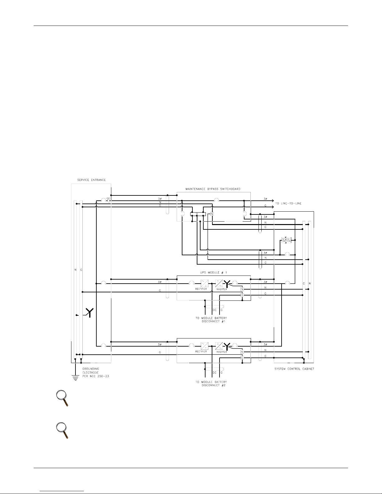
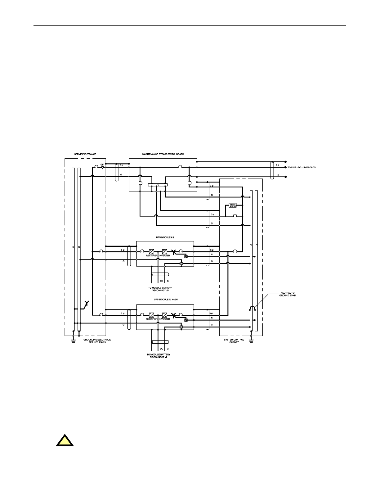
6.1 Preferred Grounding Configuration, Wye-Connected Service
The most common configuration of Series 610 UPS Multi-Module Systems is with 480 VAC input,
480 VAC output and a connected load consisting of multiple Power Distribution Units (PDUs) with
isolation transformers in the PDUs to produce 208 VAC. For Canadian customers, the UPS modules
usually have 600 VAC input and output. The same principles apply if the connected load is an isolation transformer feeding various loads. Figure 4 shows a typical installation. The Maintenance
Bypass Switchgear is shown separately for clarity, but may be contained within the System Control
Cabinet (SCC)/switchgear.
Notice that the UPS module input and the system bypass input are connected to a grounded-wye service. In this configuration, the UPS module is not considered a separately derived source.
All of the UPS module output neutrals are solidly connected to the SCC neutral. A parity-sized neutral is recommended between the UPS module and the SCC for best system performance. The SCC
neutral is solidly connected to the building service neutral, which is bonded to the grounding conductor at the service entrance equipment.
The isolation transformers in the PDUs are considered a separately derived source. Therefore the
PDU neutral should be bonded to the PDU grounding conductor and connected to a local grounding
electrode in compliance with NEC 250-26. (PDUs are connected to the critical load output of the SCC,
but are not shown in Figure 4 for clarity.)
Figure 4 Preferred grounding configuration, wye-connected service
NOTE
Impedance-grounded wye sources require an Isolated Neutral Kit in addition to the grounding
and neutral conductors shown above—see 6.5 - Grounding Configuration, Corner-
Grounded Delta or Impedance-Grounded Wye.
NOTE
If there is a 4-pole Automatic Transfer Switch (ATS) between the service entrance and the UPS,
this configuration cannot be used. Refer to 6.2 - Alternate Grounding Configuration, Wye-
Connected Service or 6.3 - Preferred Grounding Configuration With Isolated Bypass
to determine a suitable configuration.
UPS MODULE N, N=2-6
14
Configuring Your Neutral and Ground Connections
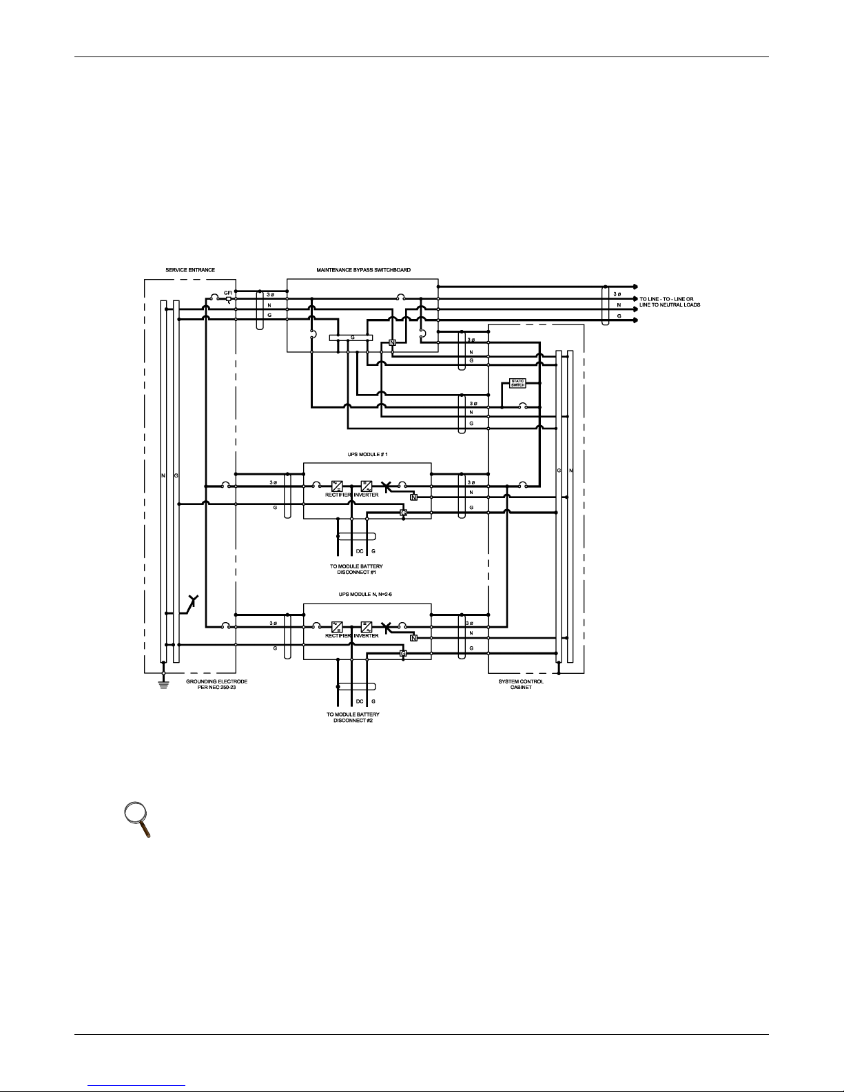
6.2 Alternate Grounding Configuration, Wye-Connected Service
This configuration must NOT be used when single-phase loads are directly connected to the UPS.
The alternate configuration is similar to that shown in 6.1 - Preferred Grounding Configuration,
Wye-Connected Service, except that the service entrance neutral is not brought into the UPS module. In this configuration, the UPS output transformer is considered a separately derived source. The
UPS module neutral is bonded to the UPS ground, which is connected to a local grounding electrode
in accordance with NEC 250-26.
Please note that this configuration represents a price/performance trade-off. Whenever the UPS module transfers to or from bypass, two AC sources (input and bypass) are briefly connected together and
circulating current must flow. In the previous configuration, the current flows through the neutral
conductor. In this configuration, the current flows through the ground path, possibly tripping ground
fault interrupters (GFIs) and distorting the bypass waveform reference.
Proper adjustment of ground fault interrupters is necessary to avoid unwanted tripping.
Figure 5 Alternate grounding configuration, wye-connected service
This configuration is reserved for applications that meet all the following criteria:
• The facility has wye-connected service.
• The module rectifier input and bypass input are fed from the same source.
• The connected load is strictly 3-wire (such as one or more PDUs) and does not require a neutral from the UPS.
• Special precautions are taken to prevent tripping the ground fault interrupters. The time
delay should be set to at least 0.2 seconds to prevent tripping when the UPS performs a transfer or retransfer operation.
CAUTION
!
Failure to properly set the ground fault interrupters could cause loss of power to the critical
load.
15

Configuring Your Neutral and Ground Connections
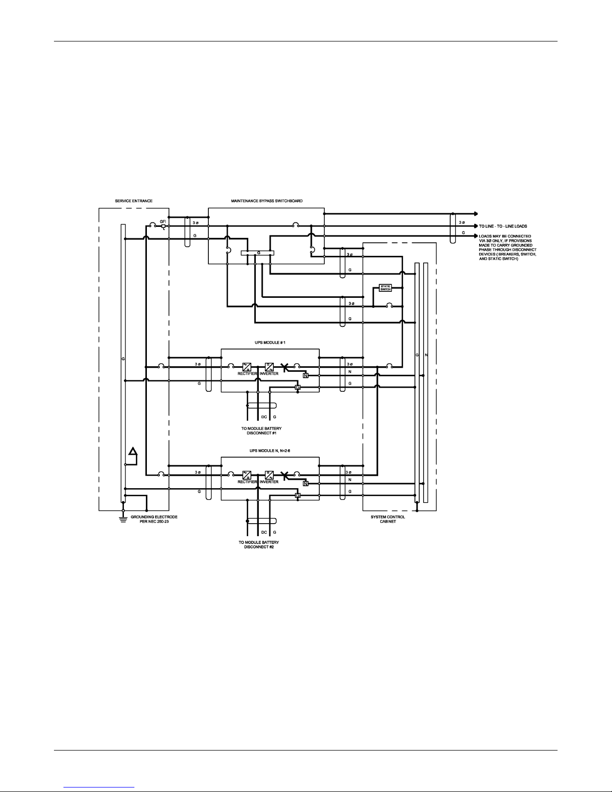
6.3 Preferred Grounding Configuration With Isolated Bypass
Another configuration in this power range is the Multi-Module System with 480 or 600 VAC input,
208 VAC output, a Bypass Isolation Transformer and a connected load consisting of multiple distribution panelboards or switchboards. Figure 6 shows a typical installation.
The Bypass Transformer provides isolation and may step down the voltage to the bypass input. The
Bypass Transformer and the SCC together constitute a separately derived system, since there is no
direct electrical connection between the input (service entrance) circuit conductors and the output circuit conductors.
NOTE
Figure 6 shows a wye-connected source, but the same grounding scheme would apply for a
delta source at the service entrance.
The bonding of the neutral to the grounding conductor can theoretically be done at either the SCC or
the Bypass Transformer. However, we recommend bonding at the Bypass Transformer because the
UPS module will sometimes be powered down for maintenance and its output transformer will be out
of the circuit. The neutral should be bonded to ground and a local grounding electrode should be
installed at the Bypass Transformer, per NEC 250-30.
Figure 6 Preferred grounding configuration with isolated bypass
Features of this configuration include:
• The UPS receives its bypass neutral from the Bypass Transformer
• The output is isolated from the input circuit conductors, and
• Some amount of common-mode noise attenuation can be obtained for sensitive loads if the
UPS module and Bypass Transformer are located close to sensitive loads.
16
Configuring Your Neutral and Ground Connections
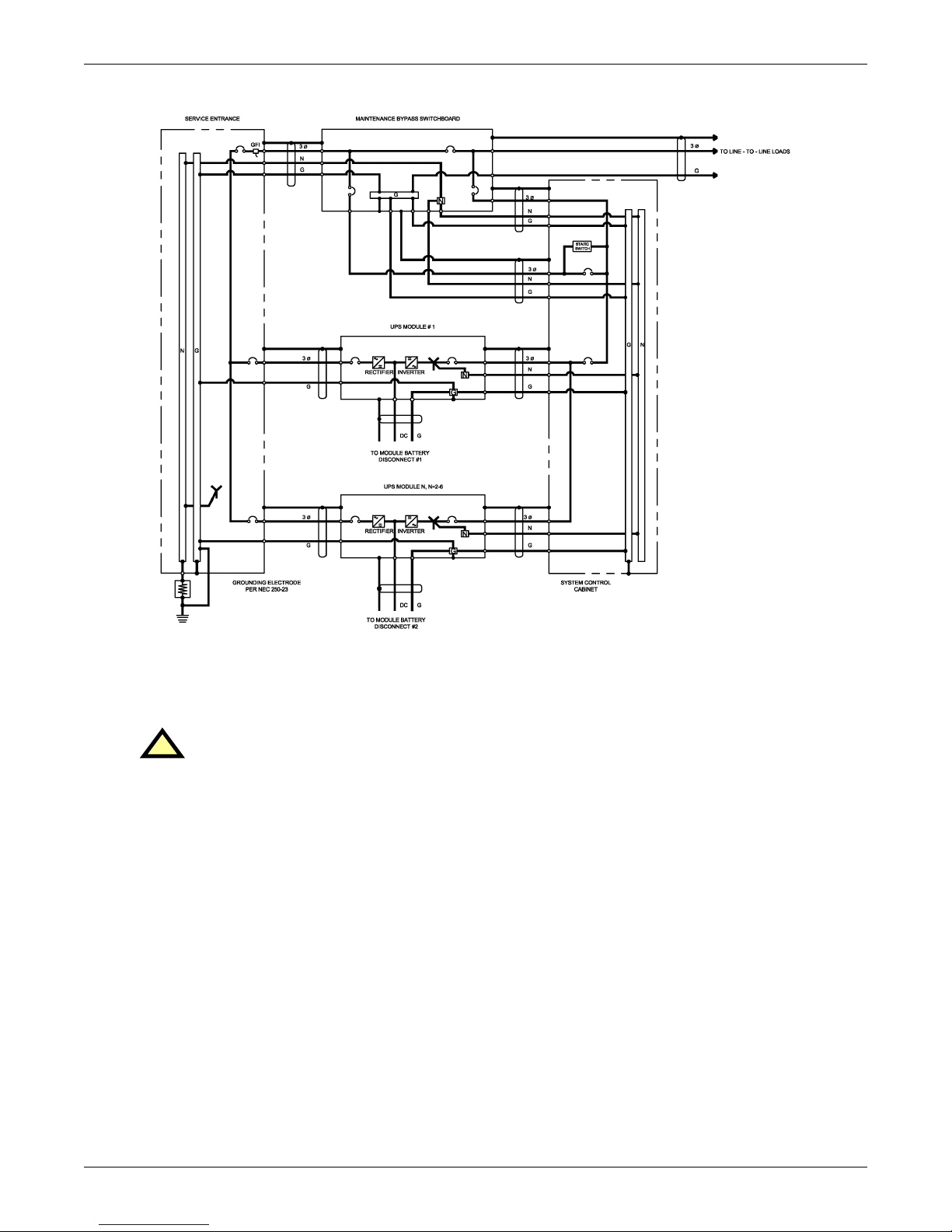
6.4 Alternate Grounding Configuration, Non-Isolated
A few applications in this power range have 208 VAC input and output, and a connected load consisting of multiple Power Distribution Units (PDUs), panelboards, switchboards or other items of load
equipment which do not have isolation transformers.
Notice in Figure 7 that the UPS system main input and bypass input are connected to a groundedwye service. In this configuration, the UPS system is not considered a separately derived source.
The UPS module output neutral and the load neutral are solidly connected to the building service
neutral, which is bonded to the grounding conductor at the service entrance equipment.
Figure 7 Alternate grounding configuration, non-isolated
This arrangement may be used for systems with 208 VAC input and output. However, it does not provide any isolation or common-mode noise attenuation for sensitive loads. For this reason, this configuration is not a preferred installation method.
NOTE
If there is a 4-pole Automatic Transfer Switch (ATS) between the service entrance and the UPS,
this configuration cannot be used. Refer to 6.3 - Preferred Grounding Configuration With
Isolated Bypass to determine a suitable configuration.
17
Configuring Your Neutral and Ground Connections
6.5 Grounding Configuration, Corner-Grounded Delta or Impedance-Grounded Wye
As previously mentioned, Series 610 SCC requires a bypass input neutral for sensing and monitoring.
With a wye-connected input source, the installer should always connect the building service neutral to
the System Control Cabinet (SCC) output neutral to achieve this. When the building service is deltaconnected, however, the installer must take special steps to ensure reliable UPS functioning.
If the building service is corner-grounded delta or impedance-grounded wye, the UPS requires the
Series 610 Isolated Neutral Kit, as do each of the UPS modules. This kit uses control isolation transformers to create a reference point. For this application, the SCC output neutral must not be bonded
to the SCC ground.
Figure 8 Preferred grounding configuration, corner-grounded delta or impedance-grounded wye
18
Configuring Your Neutral and Ground Connections
Figure 9 Preferred grounding configuration, impedance-grounded wye
These configurations have the same restrictions as explained in 6.2 - Alternate Grounding Configuration, Wye-Connected Service, except for the wye input. The UPS input and bypass must be fed
from the same source. The load must be strictly 3-wire. And the GFI time delay should be set to at
least 0.2 seconds to prevent tripping during transfer or retransfer operations.
CAUTION
!
Failure to properly set the ground fault interrupters could cause loss of power to the critical
load.
19
Configuring Your Neutral and Ground Connections
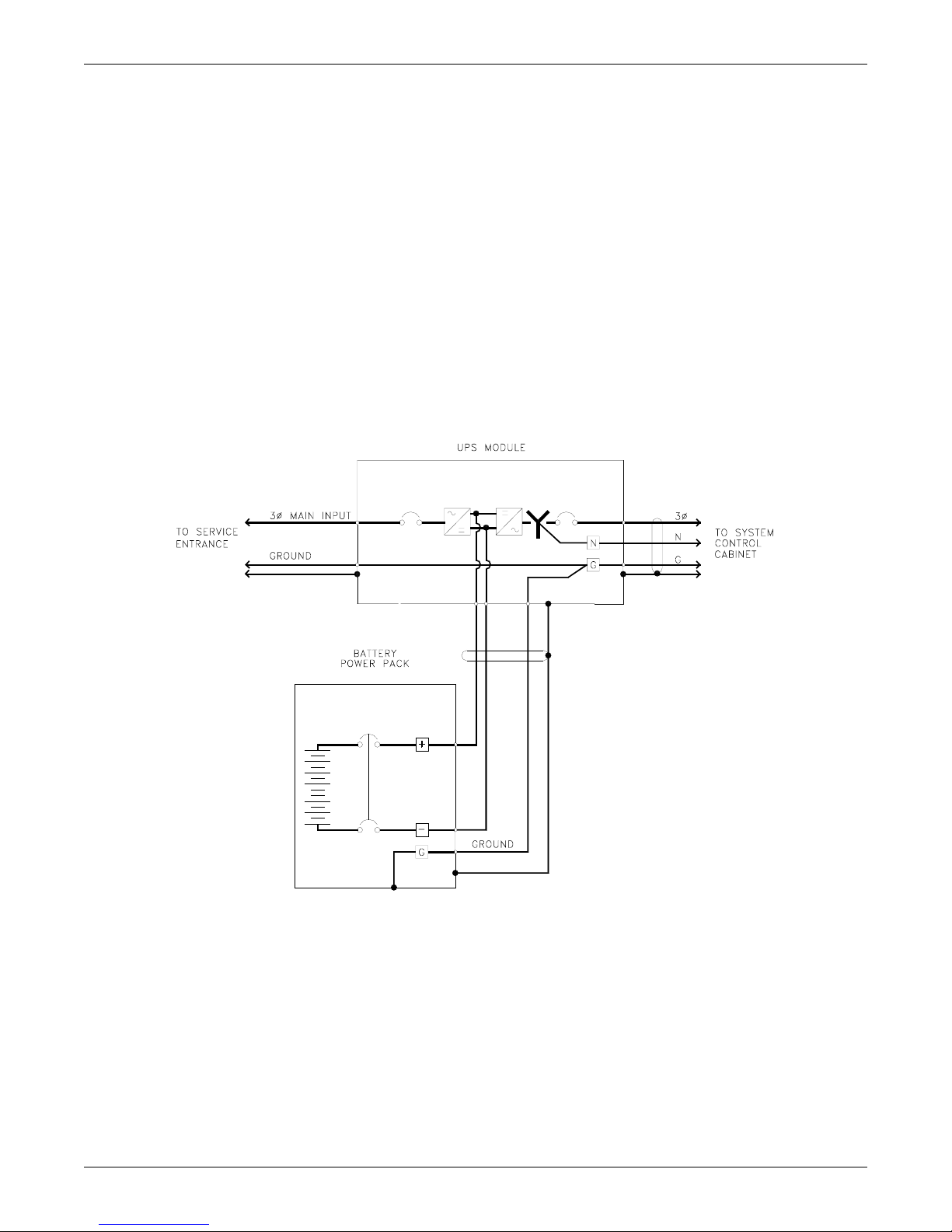
6.6 Preferred Grounding Configuration, Battery Systems
Open-rack battery systems, depending on local code requirements and customer preference, are
normally:
1. Floating (ungrounded),
2. Center-tapped and floating or
3. Center tapped and grounded.
Battery cabinet systems must be connected as floating (ungrounded) systems—Option 1 above.
Center-tapped or grounded battery systems are not possible with battery cabinet systems.
Whether the battery system is open-rack or cabinet, the metal rack parts or cabinet must be grounded
to the UPS module ground bus.
Figure 10 illustrates how a simple, one-cabinet system would be grounded. For systems with multi-
ple cabinets, the same configuration would apply. However, for simplicity, the installer can connect
all the battery cabinet grounds for a particular module together and run a single ground conductor to
that UPS module ground (in the same conduit as the phase conductors).
Figure 10 Preferred grounding configuration, battery systems
20

7.0 WIRING CONSIDERATIONS
WARNING
!
All power connections must be completed by a licensed electrician experienced in wiring this
type of equipment. Wiring must be installed in accordance with all applicable national and
local electrical codes. Improper wiring may cause damage to the equipment or injury to
personnel.
Verify that all incoming high and low voltage power circuits are de-energized and locked out
before installing cables or making any electrical connections.
Refer to Appendix A and drawings in 10.0 - Installation Drawings. Determine AC currents for
your system (kVA, voltage and options). Also refer to the equipment nameplate for the model number,
rating and voltage. For wire termination data, refer to Tables 2 through 4. Consult your facility’s
breaker coordination study to ensure proper handling of fault currents.
NOTE
The instantaneous trip setting of the bypass feeder breaker should be high enough to
accommodate short-duration overloads. The bypass static switch inside the SCC can draw up
to 10 times the system’s rated current for up to three cycles in the event of a downstream fault.
NOTE
Use 75°C copper wire. Select wire size based on the ampacities in Table 5 of this manual, a
reprint of Table 310-16 and associated notes of the National Electrical Code (NFPA 70).
Wiring Considerations
CAUTION
!
The weight of power cables must be adequately supported to avoid stress on busbars and lugs.
In addition to weight support, the following restraining method is recommended to control
cable movement during external fault conditions:
• Wrap line cables together at 6 and 12 in. (152 and 305mm) from the terminals with five
wraps of 3/8 in. (9.5mm) nylon rope or equivalent (tensile strength of 2000 lbs.; 907kg).
• Support the remainder of the cable with five wraps every 6 in. (152mm) or one wrap every
1in. (25mm).
21

7.1 Power Wiring
1. Power wiring—rectifier input, bypass input, UPS output and battery cables—must be run in
individual, separate conduits or cable trays. Refer to the Outline and Terminal Details drawings
(Figures 14 through 30, 47, 49, 51, 53 and 75 through 78) for locations of the various power
connections within the UPS and ancillary equipment. In particular, note the location of the
rectifier input power connections.
CAUTION
!
Power and control wiring must be separated!
2. Observe local, state and national electrical codes. Verify utility power and its overcurrent
protection rating will accommodate the UPS input rating, including battery recharging.
3. A safety ground wire must be run from the building ground to a ground point in the UPS Module
Cabinets, ancillary equipment and the Power-Tie Cabinet (if applicable). See 6.0 - Configuring
Your Neutral and Ground Connections. The grounding conductor shall comply with the
following conditions of installation:
a. An insulated grounding conductor must be sized in accordance with the NEC and local codes.
It must be green (with or without one or more yellow stripes) and be installed as part of the
branch circuit that supplies the unit or system.
b. The grounding conductor described above is to be grounded to earth at the service equipment
or, if supplied by a separately derived system, at the supply transformer or motor-generator
set in accordance with the instructions in 6.0 - Configuring Your Neutral and Ground
Connections.
c. The attachment-plug receptacles in the vicinity of the unit or system are all to be of a
grounding type, and the grounding conductors serving these receptacles are to be connected to
earth ground at the service equipment.
4. Observe clockwise phase rotation of all power wiring. Phase A leads Phase B leads Phase C.
A qualified electrician should check the phase rotation.
5. AC power cables must be rated to meet NEC requirements for voltage drop at the maximum rated
system current. DC power cables from the UPS to the battery terminals and return must be sized
for less than 2 volts total loop drop at the maximum rated system current.
6. If site equipment includes a backup generator and automatic transfer switch(es), consult the
manufacturers of those devices for information on sizing and interfacing to the UPS system.
7. Removable access plates are available for power wiring. Refer to the Outline Drawings for your
particular model (Figures 14, 16, 18, 20, 22, 24, 26, 28, 47, 49, 51,
Wiring Considerations
53 and 75 through 78).
CAUTION
!
After cutting holes in the access plates, be certain that no foreign matter (metal shavings,
sawdust, insulation or wire fragments, etc.) remains inside the UPS. Likewise be certain to
block any “extra” holes in the plates through which foreign matter could later enter the UPS.
22
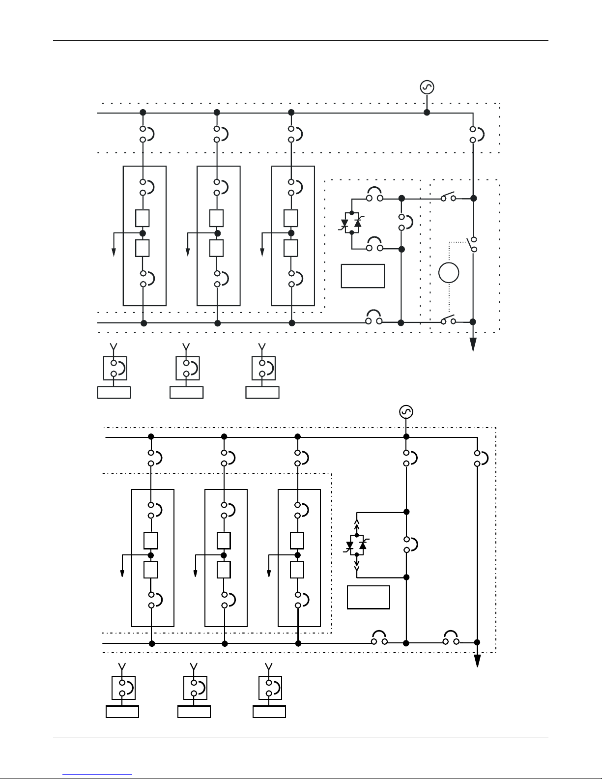
Figure 11 Power single line diagrams, Multi-Module configurations*
d
* These configurations are for illustrative purposes only. They represent
only a sample of the possible configurations. Refer to the submittals
supplied with your order for more information or for order-specific details.
Wiring Considerations
Battery
CB1
CB
MBD
RIB RIB
#3UPS
R
I
I
2
Battery
CB1
CB2
MBD
RIB
#2UPS
R
I
I
CB1
CB2
#1UPS
SBS
R
I
I
System
Controls
UOB
Output
SBB
BFB
BIB
MBB
SKRU
MIB
SCCT
To Critical Loa
Battery
MBD
SCCT
(can accomodate up to 6 UPS modules)
RIB RIB BIB
#3UPS
CB1
R
I
CB2 CB2
MBD
Battery
Battery
#2UPS
CB1
R
I
CB2
MBD
Battery
CB1
MBD
RIB
#1UPS
SBS
R
I
Controls
System
UOB
Output
SBB
SBB
MBB
MIB
SCCI
To Critical Load
SCCI / SCCC
(can accomodate up to 6 UPS modules)
23

Table 1 Abbreviations for circuit breakers
BFB Bypass Feeder Breaker
BIB Bypass Input Breaker
CB1 Module Input Breaker
CB2 Module Output Breaker
MBB Maintenance Bypass Breaker
MBD Module Battery Disconnect
MBFB Maintenance Bypass Feeder Breaker
MIB Maintenance Isolation Breaker
RIB Rectifier Input Breaker
SBB System Bypass Breaker
SSB Static Bypass Switch
UOB UPS Output Breaker
7.2 Control Wiring
Control wiring must be flexible stranded, tinned copper and run in individual separate steel conduits.
Control wiring must be separated from power wiring. In addition, each control wiring cable group
should be run in a separate conduit to minimize control signal interference.
Wiring Considerations
Refer to the Control Connection Locations and Control Wire Lists, Figures 55 through 74. Notice
that there are nine cable groups in a typical system:
• Cable group 1 carries signals for the Module Battery Disconnect.
• Cable group 2 is for the remote communications options: modem, remote terminal and remote
CRT.
• Cable group 3 carries signals for the Remote Emergency Module Off and Remote Emergency
Power Off.
• Cable group 4 carries signals for the optional Remote Monitor Panel.
• Cable group 5 is for the optional SiteScan system.
• Cable group 6 carries signals for the reduced battery charge limit and the reduced input current
limit.
• Cable group 7 carries signals to and from the maintenance bypass switchgear.
• Cable groups 20 and 21 carry signals for general housekeeping, modules to SCC.
Other cable groups will be required for other optional equipment. If your system has any installed
options, special wire lists will be included in your Submittal Drawing Package. Contact your Liebert
Sales Representative for assistance if the submittal drawings have been lost or misplaced.
Figures 55 through 57 show the typical location of control connections inside the UPS and SCC. The
position of a particular control connection may be different for your system, depending on the model
and the installed options.
NOTE
The UPS control and communication wiring are considered Class 2 circuits by NEC
standards. However, NEC Class 1 wiring methods are required for these circuits to ensure
proper operation of the UPS.
24
 Loading...