

Page 1
SAPAG
Sapag Type 7700 pressure relief valves
Installation, Maintenance and Adjustment Instruction
General
Sapag valves have been tested and adjusted at the factory. As service conditions differ it may be
necessary to make slight adjustments. These adjustments are easily made if the instructions below
are carefully followed.
Warning
To have trouble free performance be sure to thoroughly clean the inlets and outlets of
valves before installing.
Storage and handling
Valves are often on hand at the job site months before they are installed. Unless properly stored
and protected, valve performance may be adversely affected. Rough handling and dirt may damage
or cause misalignment of the valve parts. It is recommended that the valves be left in their original
shipping containers and that they be stored in a warehouse or as a minimum on a dry surface with
a protective covering until they are used.
Pressure relieving valves must be handled carefully and never subjected to sharp impact loads.
They should not be struck, bumped or dropped. Rough handling may alter the pressure setting,
deform valve parts and adversely affect seat tightness and valve performance.
Attention
The safety of lives and property often
depends on the proper operation of the
pressure relief valves. Consequently, the
valves should be kept clean and should be
periodically tested and reconditioned to
make sure they function properly.
WARNING
Suitability of the material and product for
the use contemplated by the buyer is the
sole responsibility of the buyer. Also storage,
installation and proper use and application are
the sole responsibility of the purchaser. Emerson
Valves & Controls disclaims any and all liability
arising out of same.
Any installation, maintenance, adjustment,
repair and testing performed on pressure relief
valves should be done in accordance with
the requirements of all applicable Codes and
Standards under which those performing such
work should maintain proper authorization
through appropriate governing authorities.
No repair, assembly and test work done by
other than Emerson Valves & Controls shall
be covered by the warranty extended by
Emerson to its customers. You assume full
responsibility for your work. In maintaining
and repairing Sapag products you should use
only parts manufactured by Emerson Valves &
Controls. Call your nearest Emerson regional
sales office or representative for a Sapag
service engineer should you wish assistance
with your field needs.
Note
Where the valve has a lever as in type F top construction, do not lift or carry valves by
thelever!
Inlet and outlet protectors should remain in place until the valve is ready to be installed on the
system.
Installation
• Inlet piping
The valve should be mounted vertically in an upright position either directly on a nozzle from the
pressure vessel or on a short connection fitting that provides a direct, unobstructed flow between
the vessel and the valve. Installing a pressure relief valve in other than this recommended position
might adversely affect its operation.
A valve should never be installed on a fitting having a smaller inside diameter than the inlet
connection of the valve.
Compliance with the above recommendations will assure clean positive valve operation.
Many valves are damaged when first placed in service because of failure to clean the connections
properly when installed.
Both the valve inlet and the vessel and/or line on which the valve is mounted must be thoroughly
cleaned of all dirt and foreign material.
• Outlet piping
Discharge piping should be simple and direct. A broken connection near the valve outlet is
preferred. The weight of the discharge piping should be carried by a separate support and be firmly
braced against swaying or vibrations.
Fittings or pipe having a smaller inside diameter than the valve outlet connections must not be
used. The flow from the valve must discharge to a safe disposal area.
The safety of lives and property often depends on the proper operation of the
pressure relief valves. The valves must be maintained according to appropriate
instructions and must be periodically tested and reconditioned to ensure that they
function correctly.
Sapag pressure relief valves described in this instruction are manufactured in accordance with the
requirements of ASME Boiler and Pressure Vessel Code, Section VIII.
www.valves.emerson.com
Emerson reserves the right to change the contents without notice SAPSB-0012-EN-1309
Eng doc: IS V 3117
Page 2
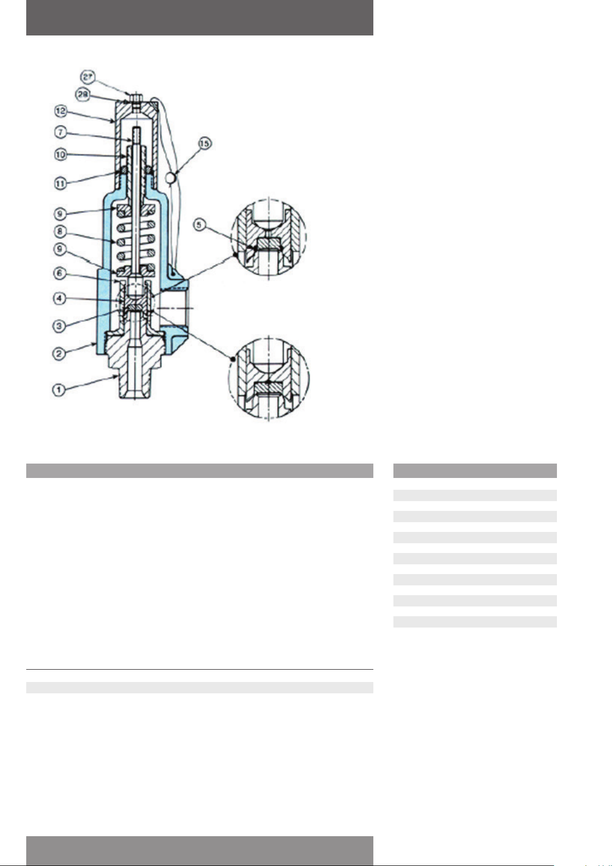
Sapag Type 7700 pressure relief valves
Installation, Maintenance and Adjustment Instruction
O-ring soft
seat
Metal-to-metal
seat
Threaded connection type 7700
Testing
Testing should be performed by trained personnel using the applicable test procedure. Follow these
guidelines for performance of the set pressure test.
• Test fluids - set pressure test
The test fluid should be air or nitrogen for valves used on gas and vapor service and water for
valves used on liquid service.
Note: Valves for steam service should be tested on steam. When steam testing is not possible,
valves for steam service may be tested on air or nitrogen. In such cases it may be necessary to
make a correction to the adjusted set pressure to compensate for the difference in temperature of
the test fluids.
• Temperature correction
When a valve is set on air or water at room temperature and then used at a higher service
temperature, the cold differential set pressure shall be corrected to exceed the set pressure using
the following temperature correction:
Operating temperature % Pressure increase
°F °C
0 to +150 -18 to +66 None
+151 to +600 +66 to 316 1%
+601 to +750 316 to 399 2%
Partslist
1 Base
2 Cylinder
3 Disc insert
4 Disc holder
5 Seat O-ring
6 Guide
7 Spindle
8 Spring
9 Spring washers
10 Adjusting bolt
11 Adjusting bolt nut
12 Type A cap
15 Seal and wire
27 Cap plug
28 Cap plug O-ring (test rod not shown)
• Valve operation
Valves intended for compressible fluid service and tested on air, nitrogen or steam will open
with a sharp, clear popping action at the set point. Valves for liquid service tested with water
are considered open at the first continuous unbroken stream of liquid flowing through the valve.
Sometimes it is helpful to install a short piece of pipe in the valve outlet to determine the opening
on water.
Emerson reserves the right to change the contents without notice page 2
Page 3

Sapag Type 7700 pressure relief valves
Installation, Maintenance and Adjustment Instruction
Set pressure
Set pressure changes
Set pressure changes beyond the Sapag specified spring range will necessitate a change in the
valve spring assembly consisting of the spring and two washers.
The new spring and washers must be obtained from Sapag and the valve must be reset and the
nameplate restamped by an authorized repair facility.
Set pressure adjustment
Before making any adjustments reduce the pressure under the valve seat to at least 25% below the
stamped opening pressure. This will prevent seat damage due to turning of the disc insert on the
nozzle seat and minimize the chance of an inadvertent opening.
Maintenance - dismantling
1. Remove the cap.
2. Before removing the adjusting bolt, take a measurement from the top of the adjusting bolt to the
top of the cylinder as a reference for resetting the valve later.
3. Loosen the adjusting bolt nut and turn the adjusting bolt counterclockwise to completely remove
the load on the spring. Unless this is done, unnecessary damage to the seat or misalignment of
the trim parts may occur when the valve is reassembled.
4. Unscrew the cylinder from the base. Lift the cylinder from the base making sure that the guide
remains on the base.
Note: If the guide is not removed with the base, invert the entire valve and remove the base.
Then remove the guide, disc holder and disc insert.
5. Remove the spindle, spring and spring washers.
6. Invert the base/guide/disc assembly and remove the base.
7. Remove the disc holder assembly.
• Metal seated valves
The disc insert is not attached to the disc holder so use care when removing this assembly.
• O-ring seated valves
Remove the disc insert by inserting a drive pin or similar tool into the hole in the disc holder and
press out the disc insert. Remove the O-ring with a suitable tool. Be careful not to damage the
O-ring groove.
Cleaning
The following instructions are general guidelines. Certain applications may require the use of
special cleaning procedures.
1. After the valve has been completely dismantled, the seats on both the nozzle and the disc insert
should be examined to determine how badly they are damaged, if at all. Any severe damage may
make it advisable to replace the parts.
2. External parts, such as the cylinder and cap, can be cleaned by immersion in a bath such as a
hot oakite solution or equivalent.
3. Internal parts, except O-rings, can be cleaned using acetone, denatured alcohol or any other
suitable solvent. Mechanical cleaning of internal parts, except seats, can be performed using fine
sandpaper or emery cloth.
Lapping of seats - metal seated valves only
Many different methods exist for lapping valve seats but certain essential steps are required for
satisfactory results. Extreme care should be taken throughout to make certain that the seats are
kept perfectly flat. The following procedure is suggested for lapping bases and disc inserts:
1. Never lap the disc against the base. Lap each part separately against a cast-iron lapping block
of proper size. These blocks hold the lapping compound in their surface pores and must be
recharged frequently.
2. Check the lapping block frequently on a good lapping block reconditioner to make certain that it
is perfectly flat.
3. If considerable lapping is required, spread a thin coat of medium coarse lapping compound
on the block. After lapping with this, lap again with a medium grade compound. Unless much
lapping is called for, the first step may be omitted. Next, lap again using a fine grade compound.
Lap the block against the seat. Do not rotate the block continuously, but use an oscillating
motion as in grinding automobile valves.
4. When the seat is flat and all nicks and marks have disappeared, remove all compound from the
lapping block and seat. Apply polishing compound to another block and lap the seat with this.
As the lapping nears completion, only the compound left in the pores of the block should be
present. This should give a very smooth finish. If scratches appear, the cause is probably dirty
lapping compound. These scratches should be removed by using a compound free from foreign
matter.
5. After wiping off all compounds, the valve is ready for assembly.
Emerson reserves the right to change the contents without notice page 3
Page 4
Sapag Type 7700 pressure relief valves
Installation, Maintenance and Adjustment Instruction
Maintenance - assembly
1. Prior to assembly, the following parts are to be coated with a lubricant/sealant such as pure
nickel “Never-Seeze” or equivalent. Other lubricants/sealants can be used depending on
service conditions.
2. Disc assembly
• Metal seated valve
With the disc holder in the inverted position, drop in the disc insert.
• O-ring soft seated valve
Coat the entire O-ring (except TFE O-rings) with Parker Super O-Lube. Insert the O-ring into the
groove in the disc holder. Push the disc insert into the disc holder. TFE O-rings may require the
use of a small press or, with care, a hammer and a punch.
3. With the guide inverted, drop in the disc assembly.
4. With the guide still inverted, install the base into the guide.
5. The base/guide/disc assembly can now be turned upright and placed into a vise or fixture for
assembly of the remaining components.
Note: Be sure to clamp only onto the wrench flats of the base.
6. Place the spring and spring washers onto the spindle.
7. While holding the spindle in place lower the cylinder into place on the base and screw tightly
onto the base.
8. Screw the adjusting bolt nut onto the adjusting bolt and install into the cylinder.
9. Screw the cap onto the cylinder.
Assembly of caps and lifting lever devices
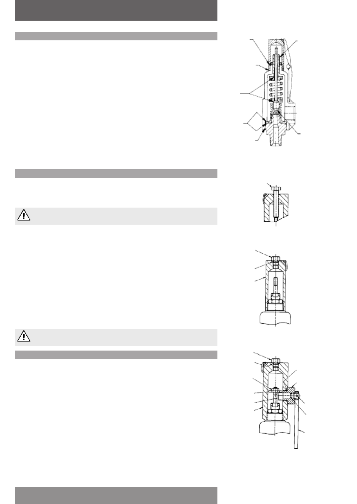
Type A (Screwed Cap with Test Rod)
Apply pure nickel Never-Seeze to the cap sealing surface and screw the cap onto the top of the
cylinder. Tighten the cap with a suitable wrench. Install the cap plug O-ring and screw the cap plug
into the cap. The test rod is installed only during system hydrostatic testing.
Cap threads
Cap to cylinder
sealing surface
Spring
washer
bevels
Guide
sealing
surfaces
Base to cylinder
threads
Adjusting
bolt threads
Spindle
point
bearing
surface
(metal
seated
valve only)
Test rod
Never install the test rod unless performing system hydrostatic testing.
Type F (Packed Lifting Lever)
1. Apply Loctite 242 or equivalent to the spindle threads. Screw the spindle nut onto the spindle.
Screw on the cap handtight.
2. Apply Parker Super O-Lube to the cam O-ring and install onto the cam. Insert the cam into the
sleeve. Install the lever onto the cam and secure with the lever pin.
3. Screw the lever assembly into the cap. If the cam interferes with the spindle nut remove the
spindle assembly and raise the spindle nut. Repeat until the spindle nut is approximately 1/16”
above the cam.
4. Once the spindle nut is in position, remove the cap and screw the locknut on the spindle and,
while firmly securing the spindle nut with locking pliers, tighten the locknut.
5. Apply pure nickel Never-Seeze or equivalent to the cap threads and to the cap sealing surface.
Screw the cap onto the top of the cylinder. Tighten the cap with a suitable wrench.
6. Apply Parker Super O-Lube or equivalent to the cam sleeve O-ring and install the O-ring. Install
the lever assembly.
7. Install the gap plug O-ring and screw the cap plug into the cap. The test rod is installed only
during system hydrostatic testing.
Never install the test rod unless performing system hydrostatic testing.
Replacement spare parts
Ordering information
Emerson recommends that a sufficient inventory of spare parts be maintained to support
process requirements. Always be sure to use genuine Sapag parts to ensure continued product
performance and warranty.
Parts
To order parts, the following information should always be included:
1. Quantity
2. Part name, i.e. (disc insert)
3. Size, style, type and valve number
4. Serial number
5. Original purchase order number (if the nameplate has been destroyed.)
Note: The size, style, set pressure and serial number can always be found on the valve nameplate.
Springs with washers
To order springs with washers, the required valve set pressure must also be specified in addition to
the other parts information. Should back pressure (fixed or variable) or elevated temperature exist
during operation, also specify these conditions.
For additional information about Sapag type 7700 pressure relief valves, see Sapag datasheet
SAPDR-0056.
Cap plug
Cap plug
O-ring
Cap
Cap plug
Cap plug O-ring
Locknut
Spindle nut
Cam
Cap
View showing valve
gagged with test rod
Type A
Cam sleeve
O-ring
Cam sleeve
Lever pin
Cam O-ring
Lever
Type F
Emerson reserves the right to change the contents without notice page 4
 Loading...