

Page 1
Rosemount™ Model 500
Helium to Hydrogen Gas Conversion Kit
Retrofit Instructions
SK-07781, Rev B
September 2019
Page 2

Notice
ROSEMOUNT (“SELLER”) SHALL NOT BE LIABLE FOR TECHNICAL OR EDITORIAL ERRORS IN THIS MANUAL OR OMISSIONS FROM
THIS MANUAL. SELLER MAKES NO WARRANTIES, EXPRESSED OR IMPLIED, INCLUDING THE IMPLIED WARRANTIES OF
MERCHANTABILITY AND FITNESS FOR A PARTICULAR PURPOSE, WITH RESPECT TO THIS MANUAL AND, IN NO EVENT, SHALL
SELLER BE LIABLE FOR ANY SPECIAL OR CONSEQUENTIAL DAMAGES INCLUDING, BUT NOT LIMITED TO, LOSS OF PRODUCTION,
LOSS OF PROFITS, ETC.
PRODUCT NAMES USED HEREIN ARE FOR MANUFACTURER OR SUPPLIER IDENTIFICATION ONLY AND MAY BE TRADEMARKS/
REGISTERED TRADEMARKS OF THESE COMPANIES.
THE CONTENTS OF THIS PUBLICATION ARE PRESENTED FOR INFORMATIONAL PURPOSES ONLY, AND WHILE EVERY EFFORT HAS
BEEN MADE TO ENSURE THEIR ACCURACY, THEY ARE NOT TO BE CONSTRUED AS WARRANTIES OR GUARANTEES, EXPRESSED OR
IMPLIED, REGARDING THE PRODUCTS OR SERVICES DESCRIBED HEREIN OR THEIR USE OR APPLICABILITY. WE RESERVE THE RIGHT
TO MODIFY OR IMPROVE THE DESIGNS OR SPECIFICATIONS OF SUCH PRODUCTS AT ANY TIME.
SELLER DOES NOT ASSUME RESPONSIBILITY FOR THE SELECTION, USE, OR MAINTENANCE OF ANY PRODUCT. RESPONSIBILITY FOR
PROPER SELECTION, USE, AND MAINTENANCE OF ANY SELLER PRODUCT REMAINS SOLELY WITH THE PURCHASER AND END-USER.
Warranty
LIMITED WARRANTY: Subject to the limitations contained in Section 2 herein and except as otherwise expressly provided
1.
herein, Rosemount (“Seller”) warrants that the firmware will execute the programming instructions provided by Seller
and that the Goods manufactured or Services provided by Seller will be free from defects in materials or workmanship
under normal use and care until the expiration of the applicable warranty period. Goods are warranted for twelve (12)
months from the date of initial installation or eighteen (18) months from the date of shipment by Seller, whichever period
expires first. Consumables and Services are warranted for a period of 90 days from the date of shipment or completion of
the Services. Products purchased by Seller from a third party for resale to Buyer (“Resale Products”) shall carry only the
warranty extended by the original manufacturer. Buyer agrees that Seller has no liability for Resale Products beyond
making a reasonable commercial effort to arrange for procurement and shipping of the Resale Products. If Buyer
discovers any warranty defects and notifies Seller thereof in writing during the applicable warranty period, Seller shall, at
its option, promptly correct any errors that are found by Seller in the firmware or Services, or repair or replace F.O.B. point
of manufacture that portion of the Goods or firmware found by Seller to be defective, or refund the purchase price of the
defective portion of the Goods/Services. All replacements or repairs necessitated by inadequate maintenance, normal
wear and usage, unsuitable power sources, unsuitable environmental conditions, accident, misuse, improper installation,
modification, repair, storage or handling, or any other cause not the fault of Seller are not covered by this limited
warranty, and shall be at Buyer's expense. Seller shall not be obligated to pay any costs or charges incurred by Buyer or any
other party except as may be agreed upon in writing in advance by an authorized Seller representative. All costs of
dismantling, reinstallation and freight, and the time and expenses of Seller's personnel for site travel and diagnosis under
this warranty clause shall be borne by Buyer unless accepted in writing by Seller. Goods repaired and parts replaced during
the warranty period shall be in warranty for the remainder of the original warranty period or ninety (90) days, whichever is
longer. This limited warranty is the only warranty made by Seller and can be amended only in a writing signed by an
authorized representative of Seller. Except as otherwise expressly provided in the Agreement, THERE ARE NO
REPRESENTATIONS OR WARRANTIES OF ANY KIND, EXPRESSED OR IMPLIED, AS TO MERCHANTABILITY, FITNESS FOR
PARTICULAR PURPOSE, OR ANY OTHER MATTER WITH RESPECT TO ANY OF THE GOODS OR SERVICES. It is understood
that corrosion or erosion of materials is not covered by our guarantee.
LIMITATION OF REMEDY AND LIABILITY: SELLER SHALL NOT BE LIABLE FOR DAMAGES CAUSED BY DELAY IN
2.
PERFORMANCE. THE SOLE AND EXCLUSIVE REMEDY FOR BREACH OF WARRANTY HEREUNDER SHALL BE LIMITED TO
REPAIR, CORRECTION, REPLACEMENT, OR REFUND OF PURCHASE PRICE UNDER THE LIMITED WARRANTY CLAUSE IN
SECTION 1 HEREIN. IN NO EVENT, REGARDLESS OF THE FORM OF THE CLAIM OR CAUSE OF ACTION (WHETHER BASED IN
CONTRACT, INFRINGEMENT, NEGLIGENCE, STRICT LIABILITY, OTHER TORT, OR OTHERWISE), SHALL SELLER'S LIABILITY TO
BUYER AND/OR ITS CUSTOMERS EXCEED THE PRICE TO BUYER OF THE SPECIFIC GOODS MANUFACTURED OR SERVICES
PROVIDED BY SELLER GIVING RISE TO THE CLAIM OR CAUSE OF ACTION. BUYER AGREES THAT IN NO EVENT SHALL
SELLER'S LIABILITY TO BUYER AND/OR ITS CUSTOMERS EXTEND TO INCLUDE INCIDENTAL, CONSEQUENTIAL OR PUNITIVE
DAMAGES. THE TERM “CONSEQUENTIAL DAMAGES” SHALL INCLUDE, BUT NOT BE LIMITED TO, LOSS OF ANTICIPATED
PROFITS, LOSS OF USE, LOSS OF REVENUE, AND COST OF CAPITAL.
2
Page 3

Safety and information notices
DANGER
WILL CAUSE DEATH
Failure to follow this warning will result in death or serious injury to personnel.
WARNING
DANGER TO PERSONNEL
Failure to follow this warning may result in serious injury to personnel.
CAUTION
MAY CAUSE DAMAGE TO EQUIPMENT
Failure to follow this warning may result in damage to the equipment.
NOTICE
Important messages will appear in this format.
3
Page 4

4
Page 5

Retrofit Instructions Contents
SK-07781 September 2019
Contents
Chapter 1 Safety requirements.......................................................................................................7
1.1 Rosemount Model 500 Gas Chromatograph safety warnings............................................................7
Chapter 2 Installation.....................................................................................................................9
2.1 Installing the Rosemount Model 500 helium to hydrogen gas conversion kit....................................9
2.2 Installing the carrier shut-off valve and pressure regulator..............................................................10
2.3 Installing the new 10-ft. (3 m) long reference detector restrictor (R2)............................................ 12
2.4 Purging the carrier gas lines............................................................................................................13
2.5 Changing the thermistors...............................................................................................................14
2.6 Adjusting the carrier pressure.........................................................................................................16
Chapter 3 Ordering information...................................................................................................23
3.1 Parts list .........................................................................................................................................23
Appendix A Engineering drawing....................................................................................................25
Rosemount Model 500 Helium to Hydrogen Gas Conversion Kit v
Page 6

Contents Retrofit Instructions
September 2019 SK-07781
vi Emerson.com/Rosemount
Page 7

Retrofit Instructions Safety requirements
SK-07781 September 2019
1 Safety requirements
1.1 Rosemount Model 500 Gas Chromatograph safety warnings
Observe these safety messages for the Rosemount Model 500 Gas Chromatograph.
WARNING
EXPLOSION HAZARD
Failure to de-energize the analyzer may cause serious injury or death to personnel.
Do not open when energized or when an explosive atmosphere may be present.
Keep cover tight while circuits are live.
WARNING
EXPLOSION/FIRE HAZARD
Failure to observe this warning may cause serious injury or death to personnel.
Do not open when an explosive atmosphere may be present.
Do not open while energized.
Use supply cables or wires suitable for at least 176 °F (80 °C).
CAUTION
EQUIPMENT DAMAGE
If the GC oven is heated without carrier flow, damage to the columns may occur.
WARNING
Physical access
Unauthorized personnel may potentially cause significant damage to and/or
misconfiguration of end users’ equipment. This could be intentional or unintentional and
needs to be protected against.
Physical security is an important part of any security program and fundamental to
protecting your system. Restrict physical access by unauthorized personnel to protect end
users’ assets. This is true for all systems used within the facility.
NOTICE
Prior to converting carrier gas to hydrogen, it is recommended to review local hazardous
area requirements to ensure compliance
Rosemount Model 500 Helium to Hydrogen Gas Conversion Kit 7
Page 8

Safety requirements Retrofit Instructions
September 2019 SK-07781
8 Emerson.com/Rosemount
Page 9

Retrofit Instructions Installation
SK-07781 September 2019
2 Installation
2.1 Installing the Rosemount Model 500 helium to hydrogen gas conversion kit
These are the instructions to install the hardware for the helium to hydrogen gas
conversion kit for the Rosemount Model 500 Gas Chromatograph.
The installation kit (P/N 2-3-0500-186) contains the hardware necessary to convert helium
to hydrogen gas for the GC.
WARNING
Before converting carrier gas to hydrogen, review local hazardous area requirements to
ensure compliance.
The procedure to convert the Rosemount Model 500 Gas Chromatograph from helium to
hydrogen gas includes:
• Changing the thermistors (P/N 3-0500-521)
• Adding a carrier shut-off valve (P/N 2-4-4000-190)
• Changing the Masoneilan carrier pressure regulator (60-110 psig) (P/N 2-4-9500-084)
to a Parker (10-100 psig) (P/N 2-4-5001-977)
• Installing the new 10-ft. (3 m) long restrictor (R2)
• Purging the carrier gas
• Adjusting the carrier pressure (MON2000 2-3-9000-522)
The contents of the kit are listed in Table 3-1 and are illustrated in Figure 3-1.
Table 2-1: Hydrogen Conversion Kit Main Components
Carrier shut-off valve Pressure regulator Gauge 0 - 100 psi Thermistors
P/N 2-4-4000-190 P/N 2-4-5001-977 P/N 2-4-5001-995 P/N 2-3-0500-521
Rosemount Model 500 Helium to Hydrogen Gas Conversion Kit 9
Page 10

Installation
September 2019 SK-07781
Retrofit Instructions
2.2 Installing the carrier shut-off valve and pressure regulator
This procedure describes installing the carrier shut-off valve as well as installing and
changing the pressure regulator.
Refer to Parts list to perform this task.
Procedure
1. Shut off the carrier and actuation gas supply.
2. Wait until the carrier gas pressure gauge reads zero psi.
3. Disconnect the carrier gas tubing from the tee fitting that is connected to the
carrier gas supply.
WARNING
Do not use hydrogen for valve actuation.
Figure 2-1: Current Carrier Gas Line Configuration Using Helium
A. Pressure switch
B. Tee fitting
C. Carrier gas input
D. Carrier gas line
10 Emerson.com/Rosemount
Page 11

Retrofit Instructions
SK-07781 September 2019
Installation
Note
The tee fitting positioning may vary, but is often found at the inlet of the carrier gas
regulator and is commonly accompanied with a reducer to take the tubing size
down to ⅛-in.
4. Choose a position to mount the carrier shut off valve on the back frame rail.
This position should be between the carrier gas inlet fitting and the carrier gas
regulator.
5. Connect a ¼-in. tubing from the tee to the input port of the SSO valve.
6. Connect the output port of the SSO valve to a ¼-in. piece of stainless steel tubing to
the input port of the new Parker pressure regulator, 10-100 psig (P/N
2-4-5001-977).
7. Use a ⅜-in. national pipe thread (NPT) to ⅛-in. Swagelok fitting to connect the
actuation gas line located at the top port of the SSO valve.
8. Connect a piece of ⅛-in. tubing from the actuation port of the SSO valve to the ⅛in. bulkhead fitting.
This is the actuation gas input port.
9. Connect the actuation line (N2) to the ⅛-in. input port.
Figure 2-2: Carrier Gas Pneumatic Connections
A. Actuation line (N2)
B. Carrier gas line, stainless steel, ¼-in. tubing
C. Tee
D. Carrier gas input (H2)
E. Blocking valve
F. ⅛-in. bulkhead, stainless steel
G. Parker pressure regulator
H. Stainless steel, ¼-in. tubing
I. Shut-off valve
Rosemount Model 500 Helium to Hydrogen Gas Conversion Kit 11
Page 12

Installation Retrofit Instructions
September 2019 SK-07781
10. Ensure that all tube fittings are properly connected. Then label the new actuation
gas inlet and reconnect gases to their appropriate entries.
2.3 Installing the new 10-ft. (3 m) long reference detector restrictor (R2)
Procedure
1. Remove the GC top cover.
2. Remove the upper enclosure insulation cover.
3. Disconnect restrictor (R2), which connects the reference carrier gas to the
reference detector.
4. Install the new 10-ft. (3 m) long restrictor.
See Figure 2-3 for reference.
Figure 2-3: New 10-ft. (3 m) Restrictor (R2)
A. Carrier gas reference side
B. Restrictor (R2)
C. From detector reference side
5. Replace the insulation cover.
6. Replace the top cover.
12 Emerson.com/Rosemount
Page 13
Retrofit Instructions
SK-07781 September 2019
Installation
2.4 Purging the carrier gas lines
Use this procedure to purge the gas chromatograph's gas lines.
Refer to Figure 2-4.
Procedure
1. Close all valves and tighten all fittings.
2. Run tubing to the GC, but do not connect.
3. Back off pressure regulator (turn counterclockwise) fully.
Refer to Figure 2-4 to complete Step 4 through Step 12.
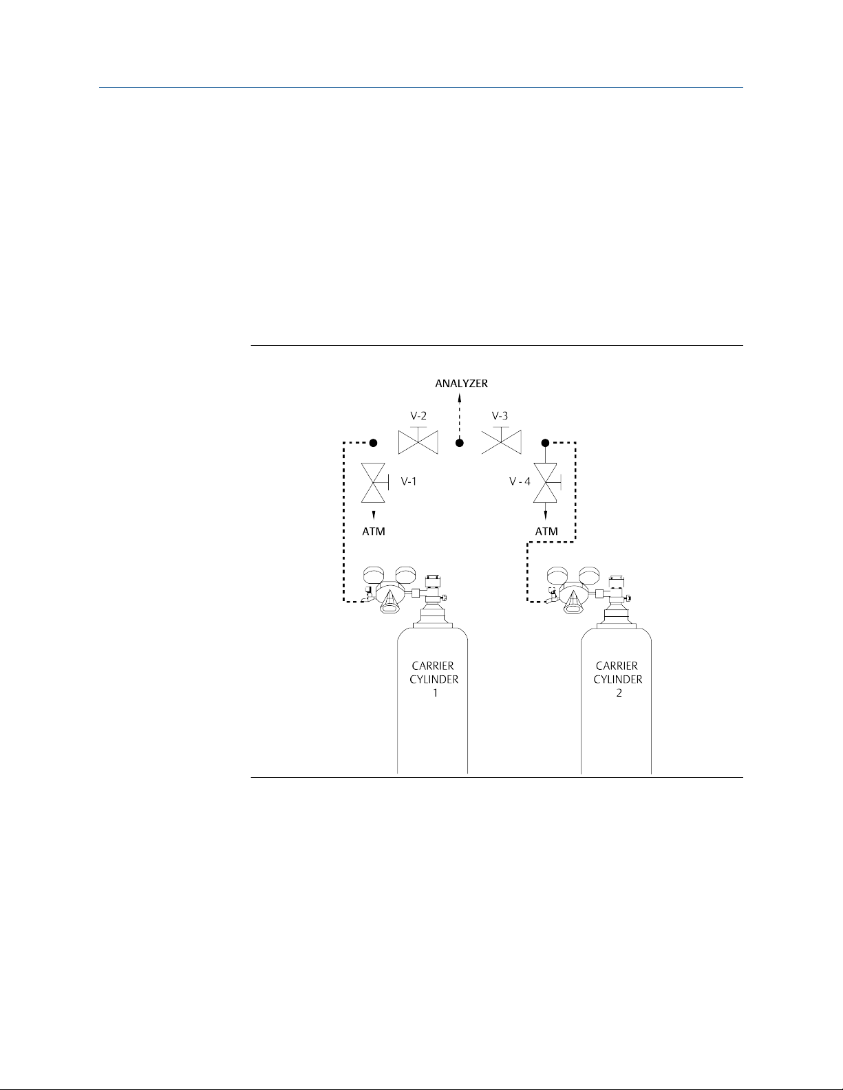
Figure 2-4: Carrier Gas Valve Configuration
4. Open cylinder valve for Carrier Cylinder 1.
The pressure indicator will read the cylinder pressure.
5. Open the shut-off valve attached to the carrier regulator.
6. Regulate pressure out of the cylinder to 20 psig; then close the cylinder valve.
7. Open V-1 (bleed valve) and let the carrier gas bleed to atmosphere until both
gauges read 0 psig and then close V-1.
8. Repeat Step 4 and Step 5 twice to purge the line to V-2.
9. Purge the line to V-3 by repeating Step 2 through Step 6, but this time, use bleed
valve V-4 and Carrier Cylinder 2.
Rosemount Model 500 Helium to Hydrogen Gas Conversion Kit 13
Page 14

Installation Retrofit Instructions
September 2019 SK-07781
10. With valves 1-4 closed, open both cylinder valves and regulate both carriers to
approximately 10 psig.
11. Open V-2 and V-3 simultaneously; then turn both cylinder valves off and let the
carrier gases bleed through the line to the GC until all gauges read 0 psig.
12. Repeat Step 8 and Step 9 twice to purge the line to the GC.
13. Leak check all the fittings carefully.
14. Let the GC run overnight before calibrating.
2.5 Changing the thermistors
Use this procedure to change the helium thermistors to hydrogen comparable
thermistors.
WARNING
EXPLOSION HAZARD
Failure to observe this warning may cause death or serious injury to personnel.
Hydrogen is potentially explosive. Use extreme caution when using hydrogen as the
gas chromatograph's carrier gas.
To prevent ignition of hazardous atmospheres, disconnect from supply circuit before
opening the enclosure. Keep tightly closed when circuits are alive. For division
installations using a conduit, a sealing device must be connected within 18 in. (460
mm).
Procedure
1. Turn off power to the gas chromatograph.
14 Emerson.com/Rosemount
Page 15

Retrofit Instructions Installation
SK-07781 September 2019
2. Remove the upper enclosure insulation cover (P/N 2-4-4500-195).
Figure 2-5: Upper Enclosure Insulation Cover
3. Remove the explosion-proof upper enclosure cover.
Figure 2-6: Upper Enclosure Explosion-Proof Cover
Rosemount Model 500 Helium to Hydrogen Gas Conversion Kit 15
Page 16

Installation
September 2019 SK-07781
4. Use a standard flathead or a Phillips screwdriver and loosen the four detector block
thermistor wiring screws (Item B).
Figure 2-7: Detector Block Wiring
A. Detector block screw
B. Thermistor wiring screws
C. Thermistor wires
D. Thermistor nuts
Retrofit Instructions
5. Use a standard flathead screwdriver and remove the two detector block screws
(Figure 2-7, Item A) and remove the detector block.
6. Remove the two ⅜-in. thermistor nuts (Figure 2-7, Item D).
7. Remove the thermistors and the PTFE seals from the detector block.
8. Replace the thermistor seals and the thermistors (Kit P/N 2-3-0500-521) that
shipped with the retrofit kit.
9. Thread the thermistors through the two ⅜-in. thermistor nuts and tighten the nuts.
Using the proper wrench, apply 20 ft.-lb. of torque.
10. Reattach the detector block using the two flathead screws.
11. Attach the terminal wires for the thermistors and tighten the four screws (see
Figure 2-7).
12. Install the upper enclosure cover (Figure 2-6). Make sure that the cover is correctly
seated and tightly closed.
13. Install the insulation cover.
14. Turn on the gas chromatograph power.
2.6 Adjusting the carrier pressure
This section describes the carrier pressure adjustment after performing the helium to
hydrogen gas conversion.
Procedure
1. Adjust the carrier pressure to approximately half of what it was with the helium.
16 Emerson.com/Rosemount
Page 17

Retrofit Instructions Installation
SK-07781 September 2019
2. Make a single run with calibration gas and see how close the chromatogram is when
compared to the chromatogram with helium. If it is too fast, reduce the carrier
pressure. If it is too slow, increase the carrier pressure.
3. Continue to make single runs and adjust the carrier pressure until it looks close to
what it was with the helium carrier.
4. If necessary, make any required valve timing changes to bring the GC back to full
function.
Use the following guide to help in valve adjustments. The guide is specific to C6+
BTU analysis, backflush to measure, dual column arrangement, but can be used for
any valve timing adjustments required using the appropriate valve and component.
Rosemount Model 500 Helium to Hydrogen Gas Conversion Kit 17
Page 18

Installation Retrofit Instructions
September 2019 SK-07781
Figure 2-8: Backflush Valve Timing
18 Emerson.com/Rosemount
Page 19

Retrofit Instructions Installation
SK-07781 September 2019
Table 2-2: Backflush Valve Timing
PA Old
RT BF TIME PA n-Pentane % Change
219 42 76822312
219 42.5 82954542 7.982355439
219 43 85914053 3.567629847
219 43.5 88965346 3.551564492
219 44 92305383 3.754312381
219 44.5 93208291 0.978174805
219 45 94027248 0.878631065
219 45.5 93370502 0.698463492
219 46 94646236 1.36631374
Rosemount Model 500 Helium to Hydrogen Gas Conversion Kit 19
Page 20

Installation Retrofit Instructions
September 2019 SK-07781
Figure 2-9: Dual Column Valve Timing
20 Emerson.com/Rosemount
Page 21

Retrofit Instructions Installation
SK-07781 September 2019
Table 2-3: Dual Column Valve Timing
BF TIME PA C3 PA C2 % Change
72 7.62+E08 5.60E+08 N/A
72.5 8.399+08 6.32E+08 12.85714
73 8.129+E08 6.70E+08 6.012658
73.5 N/A 6.87E+08 2.537313
74 N/A 6.95E+08 1.164483
74.5 N/A 6.98E+08 0.431655
75 N/A 7.01E+08 0.429799
5. Input the proper retention times into the Component Data Table.
6. Run forced calibration.
Rosemount Model 500 Helium to Hydrogen Gas Conversion Kit 21
Page 22

Installation Retrofit Instructions
September 2019 SK-07781
22 Emerson.com/Rosemount
Page 23

Retrofit Instructions Ordering information
SK-07781 September 2019
3 Ordering information
3.1 Parts list
Table 3-1: Helium to Hydrogen Conversion Kit (P/N 2-3-0500-186)
Part number Description Required Units
2-3-0500-521 Kit, 9k thermistors 1 Each
2-4-4000-119 Bulkhead union ⅛-in. stainless steel 1 Each
2-4-4000-190 Valve carrier shut-off 1 Each
2-4-5000-058 Tee, tube fitting ⅛-in. 2 Each
2-4-9202-608 M/S SLT button head screw stainless steel 6-32 x 1-in. 4 Each
2-4-9202-908 M/S SLT button head screw stainless steel 10-32 x
1-in.
2-4-9221-110 Kep nut 6-32 stainless steel 4 Each
2-4-9221-160 Kep nut 10-32 stainless steel 6 Each
2-4-9500-001 Tubing nut 1/16-in. stainless steel, male 3 Each
2-4-9500-005 Ferrule 1/16-in. rear 4 Each
2-4-9500-006 Ferrule 1/16-in. front 4 Each
2-4-9500-012 CON male ⅛ T x ⅛ NP 1 Each
2-4-9500-021 Tubing 1/16-in. female stainless steel 1 Each
2-4-9500-329 Tubing Peek 1/16-in. ODX .0035 ID .0035/.0 10 Feet
2-6-5000-152 Tag Hydrogen In SK-3983 1 Each
2-6-5000-160 Tag Valve Actuation Gas 1 Each
2-6-5000-485 Tubing 316 stainless steel 1/16 OD x .043 5 Feet
2-4-5001-977 Regulator, Carrier, 10-100 Out 1 Each
2-4-5001-995 Gauge 0-100 psi/bar, panel mount 1 Each
2-6-5000-487 Tubing ⅛ OD x.085 ID 31 3 Feet
2-6-5000-821 Tag RV 1 Each
2 Each
Rosemount Model 500 Helium to Hydrogen Gas Conversion Kit 23
Page 24

Ordering information Retrofit Instructions
September 2019 SK-07781
Figure 3-1: Helium to Hydrogen Conversion Kit Parts
24 Emerson.com/Rosemount
Page 25

Retrofit Instructions Engineering drawing
SK-07781 September 2019
A Engineering drawing
Notes
1. Change out thermistors to 3-0500-521 for H2 carrier.
2. Add valve actuation inert gas inlet that is separate from the hydrogen carrier gas
inlet.
WARNING
Do not use hydrogen for valve actuation.
3. Add carrier shut-off valve (2-4-4000-190) as shown.
4. If the carrier pressure regulator is a Masoneilan 60-110 psig regulator
(2-4-9500-084), replace it with the Parker 10-100 psig regulator (2-4-5001-977)
included in the kit.
5. Add ⅛-in. tee connections:
a. Preheat coil
b. Reference detector
c. To analytical valve
6. New reference vent.
Rosemount Model 500 Helium to Hydrogen Gas Conversion Kit 25
Page 26

SK-07781
Rev. B
2019
AMERICAS
Emerson Automation Solutions
10241 West Little York, Suite 200
Houston, TX 77040 USA
Toll Free 866 422 3683
+1 713 396 8880 (North America)
+1 713 396 8759 (Latin America)
+1 713 466 8175
gc.csc@emerson.com
EUROPE
Emerson
Neuhofstrasse 19a PO Box 1046
CH-6340 Baar
Switzerland
+41 (0) 41 768 6111
+41 (0) 41 768 6300
gc.csc@emerson.com
Linkedin.com/company/Emerson-Automation-Solutions
twitter.com/rosemount_news
Facebook.com/Rosemount
youtube.com/RosemountMeasurement
MIDDLE EAST AND AFRICA
Emerson
Emerson FZE
Jebel Ali Free Zone
Dubai, United Arab Emirates, P.O. Box 17033
+971 4 811 8100
+971 4 886 5465
gc.csc@emerson.com
©
2019 Emerson. All rights reserved.
The Emerson logo is a trademark and service mark of Emerson Electric Co. Rosemount is a
mark of one of the Emerson family of companies. All other marks are the property of their
respective owners.
ASIA-PACIFIC
Emerson
1 Pandan Crescent
Singapore 128461
Republic of Singapore
+65 6 777 8211
+65 6 777 0947
gc.csc@emerson.com
 Loading...