

Page 1

LIQ-MAN-MCL, Rev E
Rosemount™ MCL-220
Monochloramine System with Rosemount 1056 Transmitter
Manual
July 2017
Page 2

Essential instructions
Read this page before proceeding!
Your purchase from Rosemount has resulted in one of the finest instruments available for your particular application. These
instruments have been designed and tested to meet many national and international standards. Experience indicates that the
instrument's performance is directly related to the quality of the installation and knowledge of the user in operating and
maintaining the instrument. To ensure continued operation the the design specifications, read this manual thoroughly before
proceeding with installation, commissioning, operation, and maintenance of this instrument. If this equipment is used in a manner
not specified by the manufacturer, the protection provided by it against hazards may be impaired.
• Failure to follow the proper instructions may cause any one of the following situations to occur: loss of life, personal injury,
property damage, damage to this instrument, and warranty invalidation.
• Ensure that you have received the correct model and options from your purchase order. Verify that this manual covers your
model and options. If not, call 1 800 999 9307 to request the correct manual.
• For clarification of instructions, contact your Rosemount representative.
• Follow all warnings, cautions, and instructions marked on and supplied with the product.
• Use only qualified personnel to install, operate, update, program, and maintain the product.
• Install your equipment as specified in the installation instructions of this manual. Follow appropriate local and national
codes. Only connect the product to the electrical and pressure sources specified in this manual.
• Use only factory documented components for repair. Tampering or unauthorized substitution of parts and procedures can
affect the performance and cause unsafe operation of your process.
• All equipment doors must be closed and protective covers much be in place unless qualified personnel are performing
maintenance.
• If this equipment is used in a manner not specified by the manufacturer, the protection provided by it against hazards may
be impaired.
WARNING!
RISK OF ELECTRICAL SHOCK
Equipment protected throughout by double insulation.
• Installation of cable connections and servicing of this product may require access to shock and high voltage levels.
• Main power and relay contacts wired to separate power sources must be disconnected before servicing.
• Do not operate or energize instrument with the case open!
• Signal wiring connected in this box must be rated at least 240 V.
• Non-metallic cable strain reliefs do not provide grounding between conduit connections! Use grounding type bushings and
jumper wires.
• Unused cable conduit entries must be securely sealed by non-flammable closures to provide enclosure integrity in
compliance with personal safety and environmental protection requirements. Unused conduit openings must be sealed with
NEMA 4X or IP65 conduit plugs to maintain the ingress protection rating (NEMA 4X).
• Electrical installation must be in accordance with the National Electrical Code (ANSI/NFPA-70) and/or any other applicable
national or local codes.
• Operate only with front and rear panels fastened and in place over terminal area.
• Safety and performance require that this instrument be connected and properly grounded through a three-wire power
source.
• Proper relay use and configuration is the responsibility of the user.
WARNING!
This product is not intended for use in the light industrial, residential, or commercial environments per the instrument's certification
to EN50081-2.
CAUTION!
This product generates, uses, and can radiate radio frequency energy and thus can cause radio communication interference.
Improper installation or operation may increase such interference. As temporarily permitted by regulation, this unit has not been
tested for compliance within the limits of Class A computing devices, pursuant to Subpart J of Part 15 of FCC rules, which are
designed to provide reasonable protection against such interference. Operation of this equipment in a residential area may cause
interference, in which case the user at his own expenace, will be required to take whatever measures may be required to correct the
interference.
Page 3

About this document
This manual contains instructions for installation and operation of the Rosemount
MCL-220 monochloramine system.
The following list provides notes concerning all revisions of this document.
Rev level Date Notes
A 09/08 This is the initial release of the product manual. This manual has been reformatted to
reflect the Emerson documentation style and updated to reflect any change in the product offering.
B 08/09 Updated ISO/DNV approval.
C 09/11 Updated Chapter 2, Table 8-2, and Figure 8-2. Updated Troubleshooting sections
Section 9.5.5, Section 9.5.6, Section 9.6, and Section 9.7.
D 03/12 Updated addresses - mail and web.
E 07/17 Changed instances of analyzer to transmitter. Updated formatting to align with new
branding guidelines. Updated addresses on back page.
Page 4

Page 5

Contents
Contents
Chapter 1 Quick Start guide ............................................................................................................. 1
Chapter 2 Description and Specifications ..........................................................................................5
2.1 Features ......................................................................................................................................... 5
2.2 Specifications .................................................................................................................................6
2.3 Ordering information ..................................................................................................................... 7
Chapter 3 Installation .......................................................................................................................9
3.1 Unpacking and inspection .............................................................................................................. 9
3.1.1 Rosemount MCL-220 ....................................................................................................... 9
3.2 Installation ..................................................................................................................................... 9
3.2.1 General information ........................................................................................................ 9
3.2.2 Sample requirements .................................................................................................... 10
3.2.3 Mounting, inlet, and drain connections ......................................................................... 10
3.2.4 Electrical connections .................................................................................................... 11
3.2.5 Installing the sensor .......................................................................................................11
Chapter 4 Wiring ........................................................................................................................... 13
4.1 Power, alarm, and output wiring .................................................................................................. 13
4.1.1 Power ............................................................................................................................ 13
4.1.2 Analog output wiring ..................................................................................................... 13
4.1.3 Alarm wiring .................................................................................................................. 14
4.2 Sensor wiring ............................................................................................................................... 15
Chapter 5 Display and operation .................................................................................................... 17
5.1 Display ......................................................................................................................................... 17
5.2 Keypad .........................................................................................................................................18
5.3 Programming the transmitter - tutorial ........................................................................................ 20
5.4 Security ........................................................................................................................................22
5.4.1 How the security code works ......................................................................................... 22
5.4.2 Assigning security codes ................................................................................................22
5.4.3 Bypassing security codes ............................................................................................... 22
5.5 Using hold ....................................................................................................................................23
5.5.1 Purpose ......................................................................................................................... 23
5.5.2 Using the hold function ................................................................................................. 23
5.6 Configuring the main display ........................................................................................................24
Chapter 6 Programming the transmitter ........................................................................................ 27
6.1 General ........................................................................................................................................ 27
6.2 Default settings ............................................................................................................................27
6.3 Configuring, ranging, and simulating outputs .............................................................................. 29
6.3.1 Purpose ......................................................................................................................... 29
6.3.2 Definitions ..................................................................................................................... 29
6.3.3 Procedure - configure outputs ....................................................................................... 30
6.3.4 Procedure - ranging outputs .......................................................................................... 31
6.3.5 Procedure - simulating outputs ......................................................................................32
6.4 Configuring alarms and assigning setpoints ................................................................................. 34
6.4.1 Purpose ......................................................................................................................... 34
6.4.2 Definitions ..................................................................................................................... 34
Instruction Manual i
Page 6

Contents
6.4.3 Procedure - configuring alarms and assigning setpoints ................................................ 36
6.4.4 Procedure - simulating alarms ....................................................................................... 37
6.4.5 Procedure - synchronizing timers ...................................................................................39
6.5 Configuring the measurement ..................................................................................................... 40
6.5.1 Purpose ......................................................................................................................... 40
6.5.2 Definitions - chlorine ..................................................................................................... 40
6.5.3 Procedure - configuring the measurement .................................................................... 40
6.6 Configuring temperature related settings .................................................................................... 41
6.6.1 Purpose ......................................................................................................................... 41
6.6.2 Definitions ..................................................................................................................... 41
6.6.3 Procedure - configuring temperature related settings ................................................... 42
6.7 Configuring security settings ........................................................................................................43
6.7.1 Purpose ......................................................................................................................... 43
6.7.2 Procedure - configuring security settings ....................................................................... 43
6.8 Resetting the transmitter ............................................................................................................. 44
6.8.1 Purpose ......................................................................................................................... 44
6.8.2 Procedure - resetting the transmitter ............................................................................ 44
Chapter 7 Calibration ..................................................................................................................... 47
7.1 Introduction .................................................................................................................................47
7.2 Calibrating temperature ...............................................................................................................47
7.2.1 Purpose ......................................................................................................................... 47
7.2.2 Procedure ...................................................................................................................... 47
7.3 Calibration - monochloramine ......................................................................................................49
7.3.1 Purpose ......................................................................................................................... 49
7.3.2 Procedure - zeroing the sensor ...................................................................................... 50
7.3.3 Procedure - calibrating the sensor ..................................................................................52
7.4 Calibration - analog outputs ......................................................................................................... 54
7.4.1 Purpose ......................................................................................................................... 54
7.4.2 Procedure ...................................................................................................................... 54
Chapter 8 Maintenance .................................................................................................................. 57
8.1 Transmitter .................................................................................................................................. 57
8.2 Monochloramine sensor ...............................................................................................................57
8.2.1 General ..........................................................................................................................57
8.2.2 Cleaning the membrane ................................................................................................ 58
8.2.3 Replacing the electrolyte solution and membrane ......................................................... 58
8.3 Constant head flow controller ...................................................................................................... 60
8.3.1 General ..........................................................................................................................60
8.3.2 Cleaning the flow controller ...........................................................................................60
8.3.3 Other maintenance ....................................................................................................... 60
Chapter 9 Troubleshooting ............................................................................................................ 63
9.1 Overview ......................................................................................................................................63
9.2 Using the diagnostic feature .........................................................................................................63
9.3 Troubleshooting when a Fault message is showing ...................................................................... 64
9.3.1 Main Board CPU, Main Board Factory Data, and Main Board User Data errors ................. 65
9.3.2 Hardware Error .............................................................................................................. 65
9.3.3 Sensor Board Unknown, Sensor Board HW (Hardware) or SW (Software) Mismatch, or
Sensor Board Not Communicating
9.3.4 Sensor Incompatible ...................................................................................................... 65
9.3.5 Sensor CPU Error ............................................................................................................66
9.3.6 Sensor RTD Open ...........................................................................................................66
.................................................................................65
ii Rosemount MCL
Page 7

Contents
9.3.7 Sensor 1 Not Detected ...................................................................................................66
9.3.8 Sensor Factory Data, Sensor Board User Data, and Sensor EEPROM Write errors ............ 67
9.3.9 Sensor ADC error ........................................................................................................... 67
9.3.10 Sensor RTD Out of Range ...............................................................................................67
9.4 Troubleshooting when a Warning message is showing .................................................................68
9.4.1 Sensor Need Factory Cal ................................................................................................ 68
9.4.2 Sensor Negative Reading ............................................................................................... 68
9.4.3 Sensor RTD Sense Open ................................................................................................. 68
9.4.4 Sensor Temperature High or Low ...................................................................................69
9.5 Troubleshooting when no error message is showing .................................................................... 69
9.5.1 Zero current is too high. ................................................................................................ 69
9.5.2 Zero current is unstable. ................................................................................................ 70
9.5.3 Sensor can be calibrated, but the current is too low. ...................................................... 70
9.5.4 Process readings are erratic. .......................................................................................... 71
9.5.5 Readings drift. ............................................................................................................... 71
9.5.6 Sensor does not respond to changes in monochloramine level. ..................................... 72
9.5.7 Readings are too low. .................................................................................................... 72
9.6 Troubleshooting when no error message is showing - general ......................................................73
9.6.1 Difference between transmitter and standard thermometer is greater than 3 °C. .......... 73
9.6.2 Current output too low .................................................................................................. 74
9.6.3 Alarm relays don't work. ................................................................................................ 74
9.6.4 Bubbles trapped against membrane. ............................................................................. 74
9.7 Simulating inputs ......................................................................................................................... 74
9.8 Simulating temperature ...............................................................................................................75
9.8.1 General ..........................................................................................................................75
9.8.2 Simulating temperature ................................................................................................ 75
Instruction Manual iii
Page 8

Contents
iv Rosemount MCL
Page 9

1 Quick Start guide
For Rosemount MCL-220 Monochloramine System
Prerequisites
Refer to Chapter 3 for installation instructions and Chapter 4 for wiring instructions.
Procedure
1. Once connections are secured and verified, apply power to the transmitter.
When the transmitter is powered up for the first time, Quick Start screens appear..
Using Quick Start is easy.
a. A backlit field shows the position of the cursor.
b. To move the cursor left or right, use the keys to the left or right of the ENTER key.
To scroll up or down or to increase or decrease the value of a digit, use the keys
above and below the ENTER key. Use the left and right keys to move the decimal
point.
c. Precc ENTER to store a setting. Press EXIT to leave without storing changes.
Pressing EXIT also returns the display to the initial Quick Start screen.
d. A vertical black bar with a downward pointing arrow on the right side of the
screen means there are more items to display. Continue scrolling down to
display all the items. When you reach the bottom of the list, the arrow points up.
Quick Start guide
2. Choose the desired language. Scroll down to display more choices.
3. The next step is to configure sensor 1. Sensor 1 is the total chlorine sensor. The
screen has two control boxes.
For measurement, choose Total chlorine.
a.
b. Choose the desired units, mg/L or ppm.
4. Choose Monochloramine for sensor 1 (S1).
Instruction Manual 1
Page 10

Quick Start guide
5. Choose the desired units for chlorine.
6. Choose the desired temperature units.
The main display appears. The outputs and alarms (if an alarm board is present) are
assigned to default values.
7.
To change outputs, alarms, and other settings, go to the main menu and choose
Program. Follow the prompts.
A menu tree is on the following page. To calibrate the sensor, refer to Section.
2 Rosemount MCL
Page 11

Quick Start guide
Instruction Manual 3
Page 12

Quick Start guide
4 Rosemount MCL
Page 13

Description and Specifications
2 Description and Specifications
2.1 Features
The Rosemount MCL monochloramine system is intended for measuring monochloramine
in fresh water.
This system uses a membrane-covered amperometric sensor. A polarizing voltage applied
to a gold mesh cathode behind the membrane destroys the monochloramine diffusing
through the membrane and keeps the concentration of monochloramine in the sensor
equal to zero. The current generated by the cathode reaction is proportional to the rate of
diffusion of monochloramine through the membrane. Because the concentration of
monochloramine in the sensor is zero, the diffusion rate and the current are proportional
to the concentration of monochloramine in the sample.
Diffusion rate also depends on membrane permeability, which is a function of
temperature. An RTD in the sensor continuously measures the temperature of the sample,
and the transmitter automatically corrects the raw sensor current for temperature
changes.
Maintenance is fast and easy. Replacing a membrane requires no special tools or fixtures. A
screw cap holds the pre-tensioned membrane in place. Replacing the electrolyte solution
takes only minutes.
The Rosemount MCL-220 system includes an easy-to-use Rosemount 1056 transmitter
that features two fully programmable 4-20 mA outputs and four fully programmable
relays. The large back-lit display allows you to read monochloramine concentration at a
glance.
A constant head overflow sampler ensures correct sample flow to each sensor.
Stable monochloramine standards do not exist. The monochloramine sensor must be
calibrated using the results of a laboratory test run on a grab sample.
Instruction Manual 5
Page 14
Description and Specifications
2.2 Specifications
General SpecificationsTable 2-1:
Physical characteristics Specifications
Sample requirements • Pressure: 3 to 65 psig (122 to 549 kPa abs). A check
valve in the inlet prevents the sensor flow cells from
going dry if sample flow is lost. The check valve opens
at 3 psig (122 kPa abs). If the check valve is removed,
minimum pressure is 1 psig (108 kPa abs).
• Temperature: 0 to 50 °C (32 to 122 °F)
• Minimum flow: 3 gal/hr (11 L/hr)
• Maximum flow: 80 gal/hr (303 L/hr); high flow causes
the overflow tube to back up.
Sample conductivity > 10 µS/cm at 25 °C (77 °F)
Process connection 1/4 in. OD tubing compression fitting (can be removed and
replaced with barbed fitting for soft tubing).
Drain connection 3/4 in. barbed fitting. Sample must drain to open atmos-
phere.
Wetted parts Overflow sampler: acrylic, nylon, polycarbonate, polyester,
silicone
Monochloramine sensor: Noryl
(3)
tex
. PFTE gold mesh cathode (not normally wetted)
Response time to step change in monochloramine concentration
Weight/shipping weight 10 lb/13 lb (4.5 kg/6.0 kg) (rounded to the nearest 1 lb
(1) Noryl is a registered trademark of General Electric.
(2) Viton is a registered trademark of E.I. duPont de Nemours & Co.
(3) Zitex is a registered trademark of Performance Plastic Corp.
<60 sec to 95% of final reading for inlet sample flow of 17
gph (64 L/hr)
[0.5 kg])
(1)
, Viton
(2)
, silicone, and Zi-
Sensor SpecificationsTable 2-2:
Physical characteristics Specifications
Range 0 to 6 ppm as Cl2. For higher ranges, consult the factory.
pH range Response is practically independent of pH between pH 7.0
and 10.0. Sensor current at pH 10.0 is within 5% of sensor
current at pH 7.0.
Accuracy Accuracy depends on the accuracy of the chemical test
used to calibrate the sensor.
Linearity 2% (typ.)
Electrolyte volume 25 mL (approx.)
Electrolyte life 2 months (approx.)
6 Rosemount MCL
Page 15

Description and Specifications
Rosemount 1056 Transmitter SpecificationsTable 2-3:
Physical characteristics Specifications
Case Polycarbonate NEMA 4X/CSA 4 IP65)
Conduit openings Accepts PG13.5 or 1/2 in. conduit fittings
Languages English, French, German, Italian, Spanish, Portuguese, and
Chinese
Ambient temperature and humidity 0 to 55 °C (321 to 131 °F); relative humidity 5 to 95% (non-
condensing)
Storage temperature -20 to 60 °C (-4 to 140 °F)
Power 84 to 265 Vac, 47.5 to 65.0 Hz, switching, 15 W.
Equipment protected by double insulation.
RFI/EMI
LVD
Outputs Two 4-20 mA or 0-20 mA isolated outputs. Continuously
Alarms Four alarm relays. Any relay can be configured as a fault
Relays Form C, SPDT, epoxy sealed
Relay contact ratings
Terminal connections rating Power connector (3 leads): 18-12 AWG wire size. Current
Hazardous location approvals For more information, refer to the Rosemount 1056 prod-
EN-61326
EN-61010-1
adjustable. Linear or logarithmic. Maximum load 550 Ω.
Output dampening is user-adjustable.
alarm instead of a process alarm. Each relay can be configured independently, and each can be programmed with interval timer settings.
5A at 28 Vdc or 300 Vac (resistive)
1/8 HP at 120/240 Vac
output connectors (2 leads): 24-16 AWG wire size. Alarm
relay terminal blocks: 18-16 AWG wire size.
uct data sheet. Approvals apply to the transmitter only.
The MCL is not suitable for use in hazardous areas.
2.3 Ordering information
The Rosemount MCL-220 is a complete system for the determination of monochloramine
in water. It consists of a monochloramine sensor, Rosemount 1056 transmitter, Variopol
cable, and constant head overflow cup to control sample flow. All components are
mounted on a backplate, and the cable is pre-wired to the transmitter. Three replacement
membranes and a 4-oz bottle of electrolyte solution are shipped with the sensor.
Instruction Manual 7
Page 16

Description and Specifications
Transmitter model Description
1056-03-24-38-AN Rosemount 1056 transmitter, single input (monochlora-
Sensor model Description
499ACL-03-54-VP Monochloramine sensor with Variopol connector
Sensor cable Description
23747-04 Interconnecting cable, Variopol for Rosemount 499ACL
Part number Description
9240048-00 Tag, stainless steel (specify marking)
Component PartsTable 2-4:
mine), alarm relays, analog output, 115/230 Vac
sensor, 4 ft
AccessoriesTable 2-5:
8 Rosemount MCL
Page 17

3 Installation
3.1 Unpacking and inspection
Complete the following steps when you unpack your instrument.
1. Inspect the shipping container. If there is damage, contact the shipper immediately
for instructions.
2. Save the box.
3. If there is no apparent damage, unpack the container.
4. Ensure that all items shown on the packing list are present. If items are missing,
notify Rosemount immediately.
3.1.1 Rosemount MCL-220
The Rosemount MCL-220 consists of the following items mounted on a back plate.
1. The Rosemount 1056-03-24-38-AN with sensor cable attached.
2. Constant head overflow sampler with flow cell for monochloramine sensor.
3. The monochloramine sensor (Rosemount 499ACL-03-54-VP), three membrane
assemblies, and a bottle of electrolyte solution are in a separate package.
Installation
3.2 Installation
3.2.1 General information
1. Although the system is suitable for outdoor use, do not install it in direct sunlight or
in areas of extreme temperature.
CAUTION!
HAZARDOUS AREAS
The Rosemount MCL is not suitable for use in hazardous areas.
2. To keep the transmitter enclosure watertight, install plugs (provided) in the unused
conduit openings.
3. Install the system in an area where vibrations and electromagnetic and radio
frequency interference are minimized or absent.
4. Keep the transmittter and sensor wiring at least one foot from high voltage
conductors. Be sure there is easy access to the transmitter and sample conditioning
system.
5. Be sure there is easy access to the transmitter and sensor.
Instruction Manual 9
Page 18

Installation
3.2.2 Sample requirements
Be sure the sample meets the following requirements:
1. Temperature: 0 to 50 °C (32 to 122 °F)
2. Pressure: 3 to 65 psig (122 to 549 kPa abs)
3. Minimum flow: 3 gal/hr (11 L/hr)
3.2.3 Mounting, inlet, and drain connections
The Rosemount MCL-220 is intended for wall mounting only. Refer to Figure 3-1 for details.
The sensor screws into the flow cell adapter.
Rosemount MCL-220 Monochloramine SystemFigure 3-1:
A 1/4 in. OD tubing compression fitting is provided for the sample inlet. If desired, the
compression fitting can be removed and replaced with a barb fitting. The inlet fitting
screws into a 1/4 in. FNPT check valve. The check valve prevents the sensor flow cell from
going dry if sample flow is lost.
The sample drains through a 3/4 in. barbed fitting.
Attach a piece of soft tubing to the fitting and allow the waste to drain to open
1.
atmosphere. Do not restrict the drain line.
10 Rosemount MCL
Page 19

2. Remove the foam packing insert between the outer tube and the inner overflow
tube.
3. Adjust the sample flow until the water level is even with the central overflow tube
and excess water is flowing down the tube.
3.2.4 Electrical connections
Refer to Section 4.1 for details.
3.2.5 Installing the sensor
The Rosemount MCL is provided with the sensor cable pre-wired to the transmitter. The
terminal end of the sensor is keyed to ensure proper mating with the cable receptacle.
1. Once the key has slid into the mating slot, tighten the connection by turning the
knurled ring clockwise.
2. Screw the sensor into a plastic fitting, which is held in the flow cell by a union nut.
Do not remove the protective cap on the sensor until ready to put the sensor in
service.
Installation
Instruction Manual 11
Page 20

Installation
12 Rosemount MCL
Page 21

4 Wiring
4.1 Power, alarm, and output wiring
WARNING!
RISK OF ELECTRICAL SHOCK
Electrical installation must be in accordance with the National Electrical Code (ANSI/NFPA-70)
and/or any other applicable national or local codes.
4.1.1 Power
Wire AC mains power supply to the power supply board, which is mounted vertically on
the left hand side of the transmitter enclosure.
The power connector is at the top of the board.
Procedure
Wiring
1. Unplug the connector from the board and wire the power cable to it.
Lead connections are marked on the connector. (L is live or hot; N is neutral; the
ground connection has the standard symbol.)
2. Provide a switch or breaker to disconnect the transmitter from the main power
supply.
3. Install the switch or breaker near the transmitter and label it as the disconnecting
device for the transmitter.
4.1.2 Analog output wiring
Two analog current outputs are located on the main circuit board, which is attached to the
inside of the enclosure door.
Figure 4-1 shows the location of the terminals. The connectors can be detached for wiring.
TB-1 is output 1. TB-2 is output 2. Polarity is marked on the circuit board.
Instruction Manual 13
Page 22

Wiring
Analog output connectionsFigure 4-1:
The analog outputs are on the main board near the hinged end of the enclosure door.
For best EMI/RFI protection, use shielded output signal cable enclosed in earth-grounded
metal conduit.
Keep output signal wiring separate from power wiring. Do not run signal and power or
relay wiring in the same conduit or close together in a cable tray.
4.1.3 Alarm wiring
The alarm relay terminal strip is located just below the power connector on the power
supply board.
See Figure 4-2.
14 Rosemount MCL
Page 23

Wiring
Alarm relay connectionsFigure 4-2:
Keep alarm relay wiring separate from signal wiring. Do not run signal and power or relay
wiring in the same conduit or close together in a cable tray.
4.2 Sensor wiring
The Rosemount MCL is provided with sensor cables pre-wired to the transmitter. If it is
necessary to replace the sensor cable, refer to the instructions below.
1.
Shut off power to the transmitter.
2. Loosen the four screws holding the front panel in place and let it drop down.
3. Locate the signal board.
Slot 1 (left) Slot 2 (center)
communication input 1 (chlorine)
4. Loosen the gland fitting and carefully push the sensor cable up through the fitting as
you pull the board forward to gain access to the wires and terminal screws.
5.
Disconnect the wires and remove the cable.
Instruction Manual 15
Page 24

Wiring
6. Insert the new cable through the gland and pull the cable through the cable slot.
7. Wire the sensor to the signal board.
See Figure 4-3.
Figure 4-3:
Rosemount 499ACL-03-54-60 Sensor Wiring to Rosemount 1056
Transmitter
8. Once the cable has been connected to the board, slide the board fully into the
enclosure while taking up the excess cable through the cable gland.
9. Tighten the gland nut to secure the cable and ensure a sealed enclosure.
16 Rosemount MCL
Page 25

5 Display and operation
5.1 Display
The transmitter has a four line display.
See Figure 5-1. The display can be customized to meet your requirements. Refer to
Section 5.6.
Main DisplayFigure 5-1:
Display and operation
When the transmitter is being programmed or calibrated, the display changes to a screen
similar to the one shown in Figure 5-2. The live readings appear in small font at the top of
the screen. The rest of the display shows programming and calibration information.
Programming items appear in lists. The screen can only show four items at a time, and the
arrow bar at the right of the screen indicates whether there are additional items in the list.
See Figure 5-3 for an explanation of the arrow bar.
Programming Screen Showing Item ListFigure 5-2:
The position of the cursor is shown in reverse video. See Section 5.2 and Section 5.3 for more information.
Instruction Manual 17
Page 26

Display and operation
Arrow BarFigure 5-3:
The arrow bar shows whether additional items in a list are available.
5.2 Keypad
Local communication with the transmitter is through the membrane keypad.
Figure 5-4 and Figure 5-5 explain the operation of the keys.
18 Rosemount MCL
Page 27

Display and operation
Analyzer KeypadFigure 5-4:
Four navigation keys move the cursor around the screen. The position of the cursor is shown in reverse
video. The navigation keys are used to increase or decrease the value of a numeral. Press ENTER to select
an item and store numbers and settings. Press EXIT to return to the previous screen without storing
changes. Pressing MENU always causes the main menu to appear.
Navigation KeysFigure 5-5:
The operation of the navigation keys is shown. To move a decimal point, highlight it and then press Up or
Down.
Instruction Manual 19
Page 28

Display and operation
5.3 Programming the transmitter - tutorial
Setting up and calibrating the transmitter is easy. The following tutorial describes how to
move around in the programming menus. For practice, the tutorial also describes how to
assign ppm monochloramine values to the 4 and 20 mA analog outputs.
1. Press MENU.
The main menu screen appears. There are four items in the main menu. Calibrate is in
reverse video, meaning that the cursor is on Calibrate.
2. To assign values to the analog outputs, the Program sub-menu must be open. Use
Down to move the cursor to Program. Press ENTER.
The Program menu appears. There are six items in the Program menu. The screen
displays four items at a time. The downward pointing arrow on the right of the sreen
shows there are more items available in the menu.
3. To view the other items, use Down to scroll to the last item shown and continue
scrolling down. When you have reached the bottom, the arrow will point up. Move
the cursor back to Outputs and press ENTER.
The Outputs screen appears. The cursor is on Range. Output range is used to assign
values to the low and high current outputs.
20 Rosemount MCL
Page 29

Display and operation
4. Press ENTER.
The Output Range screen appears. The screen shows the present values assigned to
output 1 (O1) and output 2 (O2). The screen also shows which sensors the outputs
are assigned to. S1 is sensor 1. The assignments shown are the defaults for the
MCL-220. Outputs are freely assignable under the Configure menu.
5. For practice, change the 20 mA settings for output 1 to 8.5 ppm.
a.
Move the cursor to the O1 S1 20 mA: 10.00 line and press ENTER.
The screen below appears.
b. Use the navigation keys to change 10.00 to 8.5 ppm. Use Left and Right to
move from digit to digit. Use Up and Down to increase or decrease the numeral.
To move the decimal point, press Left or Right until the decimal point is
c.
highlighted. Press Up to move the decimal point to the right. Press Down to
move to the left.
d. Press ENTER to store the setting.
The display returns to the summary screen. Note that the 20 mA setting for output 1
has changed to 8.50 ppm.
Instruction Manual 21
Page 30

Display and operation
6. To return to the main menu, press MENU. To return to the main display, press MENU
and then EXIT.
5.4 Security
5.4.1 How the security code works
Security codes prevent accidental or unwanted changes to program settings or
calibrations. There are three levels of security.
1. A user can view the default display and diagnostic screens only.
2. A user has access to the calibration and hold menus only.
3. A user has access to all menus.
1. If a security code has been programmed, pressing MENU causes the security screen
to appear.
Enter the three-digit security code.
2.
3. If the entry is correct, the main menu screen appears. The user has access to the submenus the code entitles him to.
4. If the entry is wrong, the Invalid code screen appears.
5.4.2 Assigning security codes
See Section 6.7.
5.4.3 Bypassing security codes
Call the factory.
22 Rosemount MCL
Page 31

5.5 Using hold
5.5.1 Purpose
To prevent unwanted alarms and improper operation of control systems or dosing pumps,
place the alarms and outputs assigned to the sensor in hold before removing it for
maintenance.
Hold is also useful if calibration will cause an out of limits condition. During hold, outputs
assigned to the sensor remain at the last value, and alarms assigned to the sensor remain
in their present state.
Once in hold, the sensor remains in hold until hold is turned off. However, if power is loss
than restored, hold is automatically turned off.
5.5.2 Using the hold function
To put the sensor in hold, complete the following steps.
1. Press MENU.
Display and operation
The main Menu screen appears.
2. Choose Hold.
The screen shows the current hold status for each sensor.
Instruction Manual 23
Page 32

Display and operation
3. Select the sensor to be put in hold. Press ENTER.
4. To put the sensor in hold, choose Yes. To take the sensor out of hold, choose No.
5.6 Configuring the main display
The main display can be configured to meet your requirements.
1.
Press MENU.
The main menu screen appears.
2. Move the cursor to Display and press ENTER.
The screen shows the present configuration. There are four items: Main Format,
Language, Warning, and Contrast.
3. To make a change, move the cursor to the desired line and press ENTER.
A screen appears in which the present setting can be edited.
Press ENTER to store the setting.
4.
5. Main Format lets you configure the second line in the main display as well as the four
smaller items at the bottom of the display. Move the cursor to the desired place in
the screen and press ENTER.
24 Rosemount MCL
Page 33

Display and operation
6. Scroll through the list of items and select the parameter you wish to be displayed.
Once you are done making changes, press EXIT twice to return to the display menu.
7.
8. Press MENU and then EXIT to return to the main display.
The following abbreviations are used in the quadrant display.
O output
T temperature (live)
Tm temperature (manual)
M measurement
9. Choose Language to change the language used in the display.
Choose Warning to disable or enable warning messages.
10.
11. Choose Contrast to change the display contrast.
12. To change the contrast, choose either lighter or darker and press ENTER.
Every time you press ENTER, the display becomes lighter or darker.
Instruction Manual 25
Page 34

Display and operation
26 Rosemount MCL
Page 35

Programming the transmitter
6 Programming the transmitter
6.1 General
This section describes how to make the following program settings using the local keypad.
1. Configure and assign values to the analog current outputs.
2. Configure and assign values to the alarm relays.
3. Choose the type of chlorine measurement being made. This step is necessary
because the transmitter used with the MCL can measure forms of chlorine other
than monochloramine.
4. Choose temperature units or manual temperature correction for chlorine and pH (if
a pH sensor is installed).
5. Set two levels of security codes.
6. Reset the analyzer to factory default settings.
6.2 Default settings
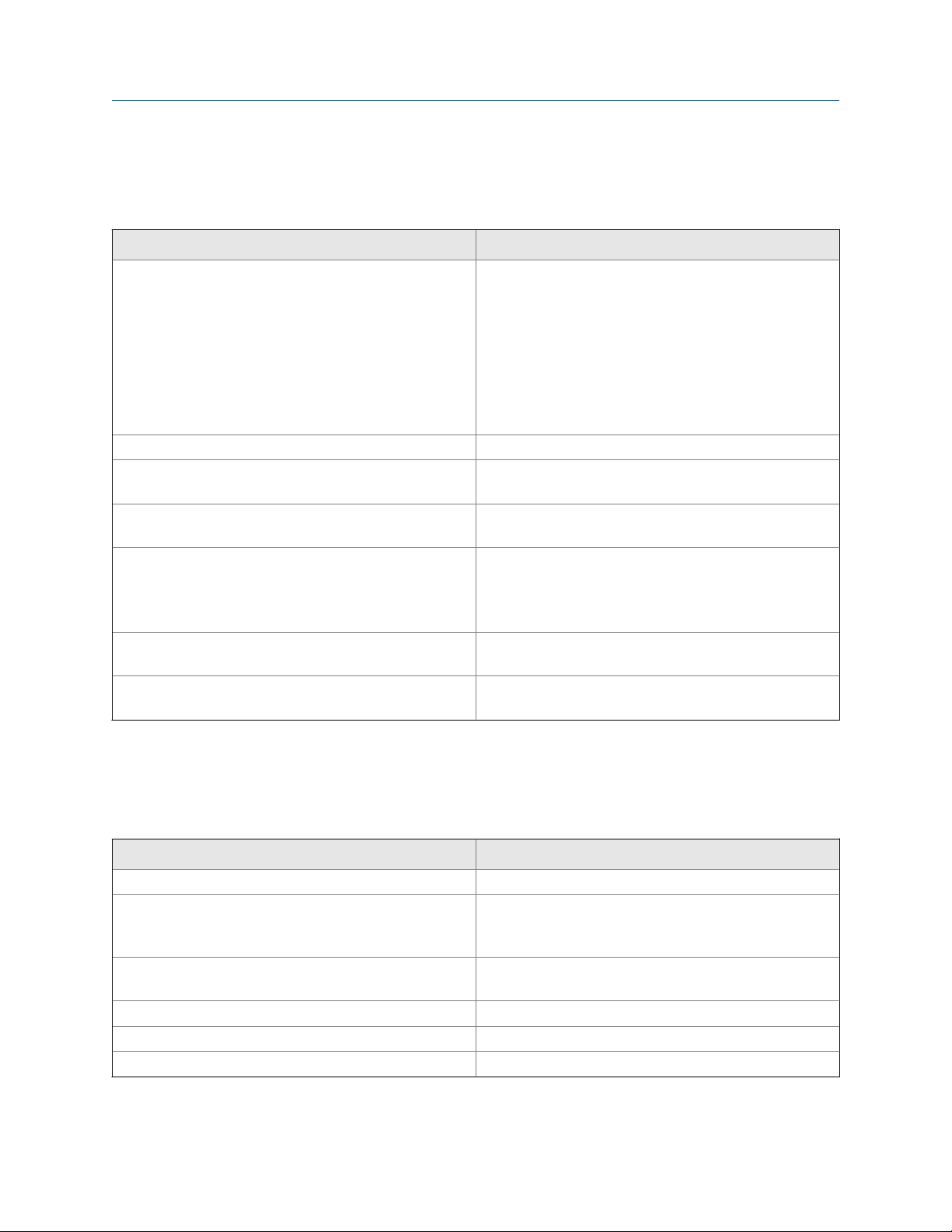
The transmitter leaves the factory with the default settings shown in Table 6-1. You can
change the settings to any value shown in the column labeled Choices.
Default SettingsTable 6-1:
Item Choices Default
Sensor assignment
Sensor 1 monochloramine monochloramine
Outputs
1. Assignments
a. output 1 monochloramine monochloramine
b. output 2 temperature temperature
2. Range 0-20 or 4-20 mA 4-20 mA
3. 0 or 4 mA setting
a. chlorine -9999 to +9999 0
b. temperature -999.9 to +999.9 0
4. 20 mA setting
a. chlorine -9999 to +9999 10
b. temperature -999.9 to +999.9 0
5. Fault current (fixed) 0.00 to 22.0 mA 12.00 mA
6. Dampening 0 to 999 sec 0 sec
Instruction Manual 27
Page 36

Programming the transmitter
Default Settings (continued)Table 6-1:
Item Choices Default
7. Simulate 0.00 to 22.00 mA 12.00 mA
Alarms
1. Logic high or low AL1 low, AL2, 3, 4, high
2. Assignments
a. AL1 and AL2 monochloramine, temperature, fault,
interval timer
b. AL3 and AL4 monochloramine, temperature, fault,
interval timer
3. Deadband 0 to 9999 0
4. Interval timer settings
a. interval time 0.0 to 999.9 hr 24.0 hr
b. on time 0 to 999 sec 10 sec
c. recovery time 0 to 999 sec 60 sec
monochloramine (sensor 1)
temperature (sensor 1)
Measurement
1. Monochloramine (sensor 1)
a. units ppm or mg/L ppm
b. resolution 0.01 or 0.001 0.001
c. input filter 0 to 999 sec 5 sec
Temperature related settings
1. Units °C or °F °C
2. Temperature compensation automatic or manual automatic
Security code
1. Calibrate/Hold 000 to 999 000
2. Program/Display 000 to 999 000
Calibration - Analog Outputs
1. 4mA 0.000 to 22.000 mA 4.000 mA
2. 20 mA 0.000 to 22.000 mA 20.000 mA
28 Rosemount MCL
Page 37

Programming the transmitter
6.3 Configuring, ranging, and simulating outputs
6.3.1 Purpose
This section describes how to configure, range, and simulate the two analog current
outputs.
Important
Configure the outputs first.
1. Configuring an output means
a. Assigning a sensor and measurement (monochloramine or temperature) to an
output.
b. Selecting a 4-20 mA or 0-20 mA output.
c. Choosing a linear or logarithmic output.
d. Set the amount of dampening on the analog outputs.
e. Selecting the value the output current goes to if the transmitter detects a fault.
2. Ranging the output means assigning values to the low (0 or 4 mA) and high (20 mA)
outputs.
3. Simulating an output means making the transmitter generate an output equal to
the value you entered.
6.3.2 Definitions
Analog current
output
Assigning an
output
Linear output
Logarithmic
output
Dampening
Fault
The analyzer provides either a continuous 4-20 mA or 0-20 mA output
signal proportional to monochloramine or temperature.
The outputs are freely assignable. Outputs can be assigned to either
monochloramine or temperature.
Linear output means the current is directly proportional to the
common logarithm of the variable assigned to the output
(monochloramine or tempreature).
Logarithmic output means the current is directly proportional to the
common logarithm of the variable assigned to the output
(monochloramine or temperature).
Output dampening smoothes out noisy readings. It also increases
response time. The time selected for output dampening is the time to
reach 63% of the final reading following a step change. Output
dampening does not affect the response time of the display.
The transmitter continuously monitors itself and the sensor for faults.
If the transmitter detects a fault, a fault message appears in the main
display. At the same time, the output current goes to the value
programmed in this section. There are two output fault modes: fixed
Instruction Manual 29
Page 38

Programming the transmitter
and live. Fixed means the selected output goes to the previously
programmed value (between 0.00 and 22.00 mA) when a fault occurs.
Live means the selected output is unaffected when the fault occurs.
Ranging an
output
The outputs are fully rangeable, including negative numbers. If the
output is logarithmic, assigned values must be positive.
6.3.3 Procedure - configure outputs
Complete the following steps to configure the analog current outputs.
1.
Press MENU.
The main Menu screen appears.
2. Move the cursor to Program and press ENTER.
The cursor is on Outputs.
3. Press ENTER.
4. Choose Configure.
30 Rosemount MCL
Page 39

Programming the transmitter
5. Choose Output 1 or Output 2.
The screen shows the present configuration. There are six items: Assign (S1 is sensor
1), Range, Scale, Dampening, Fault Mode, and Fault Value. To display the fifth and sixth
items, scroll to the bottom of the screen and continue scrolling.
6. To make a change, move the cursor to the desired line and press ENTER.
A screen appears in which the present setting can be edited.
7. Press ENTER to store the setting.
For an explanation of terms, see Section 6.3.1 and Section 6.3.2.
8. To return to the main display, press MENU and then EXIT.
6.3.4 Procedure - ranging outputs
Complete the following steps to range the outputs by assigning values to the low and high
outputs.
1. Press MENU.
The main Menu screen appears.
2. Move the cursor to Program and press ENTER.
The cursor is on Outputs.
3. Press ENTER.
Instruction Manual 31
Page 40

Programming the transmitter
4. Choose Range.
5. Choose Output 1 or Output 2.
The screen shows the present settings for the outputs. O1 is output 1, O2 is output 2,
and S1 is sensor 1.
6. To make a change, move the cursor to the desired line and press ENTER.
A screen appears in which the present setting can be edited.
7.
Press ENTER to store the setting.
For an explanation of terms, see Section 6.3.1 and Section 6.3.2.
8. To return to the main display, press MENU and then EXIT.
6.3.5 Procedure - simulating outputs
Complete the following steps to simulate an output by making the transmitter generate
an output current equal to the value you enter.
1. Press MENU.
32 Rosemount MCL
Page 41

The main Menu screen appears.
2. Move the cursor to Program and press ENTER.
The cursor is on Outputs.
3. Press ENTER.
Programming the transmitter
4. Choose Simulate.
5. Choose Output 1 or Output 2.
6. Enter the desired simulated output current.
Instruction Manual 33
Page 42

Programming the transmitter
7. To end the simulated current, press MENU or EXIT.
6.4 Configuring alarms and assigning setpoints
6.4.1 Purpose
The Rosemount MCL-220 transmitter has an optional alarm relay board. This section
describes how to configure and assign setpoints to the alarm relays, simulate alarm action,
and synchronize interval timers.
Important
Configure the alarms first.
1. Configuring an alarm means
a. Assigning a sensor and measurement (monochloramine or temperature) to an
alarm. An alarm relay can also be used as a timer.
b. Selecting high or low logic.
c. Choosing the deadband.
d. Setting the interval timer parameters.
2. Simulating an alarm means making the transmitter energize or de-energize an alarm
relay.
6.4.2 Definitions
Assigning
alarms
Fault alarm
Alarm logic,
setpoints, and
deadbands
There are four alarm relays. The relays are freely assignable to either
monochloramine or temperature. Alarm relays can also be assigned to
operate as interval timers or as fault alarms. A fault alarm activates
when the transmitter detects a fault in either itself of the sensor.
A fault condition exists when the transmitter detects a problem with
the sensor or with the transmitter itself that is likely to cause seriously
erroneous readings. If an alarm was programmed as a fault alarm, the
alarm activates. At the same time, a fault message appears in the main
display.
See Figure 6-1 and Figure 6-2.
34 Rosemount MCL
Page 43

Programming the transmitter
High Alarm LogicFigure 6-1:
The alarm activates when the chlorine concentration exceeds the high setpoint. The
alarm remains activated until the reading drops below the value determined by the
deadband.
Low Alarm LogicFigure 6-2:
The alarm activates when the chlorine concentration drops below the low setpoint.
The alarm remains activated until the reading increases above the value determined
by the deadband.
Interval timer
Any alarm relay can be used as an interval timer. Figure 6-3 shows how
the timer operates. While the interval timer is operating, the main
display, analog outputs, and assigned alarms for the sensor can be put
on hold. During hold, the main display remains at the last value.
Instruction Manual 35
Page 44

Programming the transmitter
Operation of the Interval TimerFigure 6-3:
The numbers in parentheses are the allowed values for each timer parameter.
Synchronize
timer
If two or more relays are being used as interval timers, choosing
synchronize timers will cause each timer to start one minute later than
the preceding timer.
6.4.3 Procedure - configuring alarms and assigning setpoints
Complete the following steps to configure the alarms and assign setpoints.
Press MENU.
1.
The main Menu screen appears.
2. Move the cursor to Program and press ENTER.
3. Choose Alarms.
36 Rosemount MCL
Page 45

4. Choose Configure/Setpoint.
Programming the transmitter
5. Choose Alarm 1, Alarm 2, Alarm 3, or Alarm 4.
The screens summarizes the present configuration and setpoints. There are nine
items: Setpoint, Assign (S1 is sensor 1), Logic, Deadband, Interval time, On time, Recover time,
and Hold while active. The last four items describe the operation of the timer. Only four
items are shown at a time. To view the remaining items, scroll to the bottom of the
screen and continue scrolling.
6.
To make a change, move the cursor to the desired line and press ENTER.
A screen appears in which the present setting can be edited.
7. Press ENTER to store the setting.
For an explanation of terms, see Section 6.4.1 and Section 6.4.2.
8. To return to the main display, press MENU and then EXIT.
6.4.4 Procedure - simulating alarms
Complete the following steps to make the analyzer energize or de-energize an alarm relay.
Instruction Manual 37
Page 46

Programming the transmitter
1. Press MENU.
2. Move the cursor to Program and press ENTER.
3. Choose Alarms.
The main Menu screen appears.
4. Choose Simulate.
5. Choose Alarm 1, Alarm 2, Alarm 3, or Alarm 4.
38 Rosemount MCL
Page 47

6. Choose Don't simulate, De-energize, or Energize.
7. Press MENU or EXIT to end simulation.
6.4.5 Procedure - synchronizing timers
Synch Timers is available only if two or more alarm relays have been configured as interval
timers.
1.
Press MENU.
The main Menu screen appears.
2. Move the cursor to Program and press ENTER.
Programming the transmitter
3. Choose Alarms.
The summary display shows the current Synch Timers setting (Yes or No).
4.
To make a change, choose Synch Timers and press ENTER.
A screen appears in which the present setting can be edited.
5. Press ENTER to store the setting.
For an explanation of terms, see Section 6.4.1 and Section 6.4.2.
6. To return to the main display, press MENU and then EXIT.
Instruction Manual 39
Page 48

Programming the transmitter
6.5 Configuring the measurement
6.5.1 Purpose
This section describes the following:
1. Program the transmitter to measure monochloramine using the 499ACL-03 sensor.
This step is necessary, because the transmitter can be used with other sensors to
measure other chlorine oxidants.
2. Set the level of electronic filtering of the sensor current.
6.5.2 Definitions - chlorine
Chlorine
oxidants
Filter
Resolution
Although the MCL is used to measure monochloramine only, the
transmitter used in the MCL can be used to measure other chlorine
oxidants, for example, free and total chlorine.
The transmitter applies a software filter to the raw sensor current. The
filter reduces noisy readings and increases the response time. Only the
filter time can be changed. The filter threshold cannot be changed.
If the chlorine concentration is less than 1.00 ppm (mg/L), the display
resolution can be set to 0.XX or 0.XXX.
6.5.3 Procedure - configuring the measurement
Complete the following steps to configure the transmitter to measure monochloramine.
1.
Press MENU.
The main Menu screen appears.
2. Move the cursor to Program and press ENTER.
3. Choose Measurement.
The screen summarizes the present configuration for sensor 1 (monochloramine).
There are four items: Measure, Units, Filter, and Resolution.
40 Rosemount MCL
Page 49

Programming the transmitter
4. To make a change, move the cursor to the desired line and press ENTER.
A screen appears in which the present setting can be edited.
To store the setting, press ENTER.
5.
a. For Measurement, choose Chloramine.
b. Leave Filter at the default value unless readings are noisy.
6. To return to the main display, press MENU and then EXIT.
6.6 Configuring temperature related settings
6.6.1 Purpose
This section describes how to do the following:
1.
Choose temperature units.
2. Choose automatic or manual temperature correction for membrane permeability.
3. Enter a temperature for manual temperature compensation.
6.6.2 Definitions
Automatic
temperature
correction
Manual
temperature
correction
The monochloramine sensor is a membrane-covered amperometric
sensor. It produces a current directly proportional to the rate of
diffusion of monochloramine through the membrane. The diffusion
rate, in turn, depends on the concentration of monochloramine in the
sample and membrane permeability. Membrane permeability is a
function of temperature. As temperature increases, permeability
increases. Thus, an increase in temperature will cause the sensor
current and the transmitter reading to increase even though the
concentration of monochloramine remained constant. In automatic
temperature correction, the transmitter uses the temperature
measured by the sensor to continuously correct for changes in
membrane permeability.
In manual temperature correction, the transmitter uses the
temperature you enter for correction. It does not use the actual process
temperature. Do not use manual temperature correction unless the
Instruction Manual 41
Page 50

Programming the transmitter
measurement and calibration temperatures differ by no more than
about 2 °C. Manual temperature correction is useful if the sensor
temperature element has failed and a replacement sensor is not
available.
6.6.3 Procedure - configuring temperature related settings
Complete the following steps to set the temperature units and to select automatic or
manual temperature correction.
1. Press MENU.
The main Menu screen appears.
2. Move the cursor to Program and press ENTER.
3. Choose Temperature.
The screen summarizes the present sensor configuration. There are between two
and three items. Units and S1 Temp Comp always appear. If manual temperature
compensation was selected, the manual temperature value entered for the sensor
(S1 Manual) also appears.
4. To make a change, move the cursor to the desired line and press ENTER.
A screen appears in which the present setting can be edited.
5. To store a setting, press ENTER.
For an explanation of terms, see Section 6.6.2.
6. To return to the main display, press MENU and then EXIT.
42 Rosemount MCL
Page 51

Programming the transmitter
6.7 Configuring security settings
6.7.1 Purpose
This section describes how to set security codes. There are three levels of security.
1. A user can view the default display and diagnostic screens only.
2. A user has access to the calibration and hold menus only.
3. A user has access to all menus.
The security code is a three digit number. The table shows what happens when different
security codes (XXX and YYY) are assigned to Calibration/Hold and All. 000 means no security.
Calibration/Hold All What happens
000 XXX User enters XXX and has access to all
menus.
XXX YYY User enters XXX and has access to Cal-
ibration and Hold menus only. User
enters YYY and has access to all menus.
XXX 000 User needs no security code to have
access to all menus.
000 000 User needs no security code to have
access to all menus.
6.7.2 Procedure - configuring security settings
Follow the steps below to set security codes.
1.
Press MENU.
The main Menu screen appears.
2. Move the cursor to Program and press ENTER.
3. Scroll to the bottom of the screen and continue scrolling until Security is highlighted.
Press ENTER.
Instruction Manual 43
Page 52

Programming the transmitter
4. To make a change, move the cursor to the desired line and press ENTER.
5.
6. To return to the main display, press MENU and then EXIT.
The screen shows the existing security codes.
A screen appears in which the present setting can be edited.
Press ENTER to store a change.
The security code takes effect two minutes after pressing ENTER.
6.8 Resetting the transmitter
6.8.1 Purpose
This section describes how to clear user-entered values and restore default settings. There
are three resets:
1. Resetting to factory default clears ALL user-entered settings, including sensor and
analog output calibration, and returns ALL settings and calibration values to the
factory defaults.
2. Resetting a sensor calibration to the default value clears user-entered calibration
data for the selected sensor but leaves all other user-entered data unaffected.
3. Resetting the analog output calibration clears only the user-entered analog output
calibration. It leaves all other user-entered settings unchanged.
6.8.2 Procedure - resetting the transmitter
Complete the following steps to reset the transmitter.
1. Press MENU.
The main Menu screen appears.
2. Move to Program and press ENTER.
44 Rosemount MCL
Page 53

Programming the transmitter
3. Scroll to the bottom of the screen and continue scrolling until Reset Analyzer is
highlighted. Press ENTER.
4. Choose whether to reset all user-entered values (Factory Defaults), sensor calibration
(Sensor Cal Only), or output calibration (Output Cal Only).
If you choose Sensor Cal Only or Output Cal Only, a second screen appears in which you
can select which sensor or output calibration to reset.
5.
To return to the main display, press MENU and then EXIT.
Instruction Manual 45
Page 54

Programming the transmitter
46 Rosemount MCL
Page 55

7 Calibration
7.1 Introduction
The Calibrate menu allows you to do the following:
1. Calibrate the temperature sensing element in the monochloramine sensor.
2. Calibrate the monochloramine sensor.
3. Calibrate the analog outputs.
7.2 Calibrating temperature
7.2.1 Purpose
The monochloramine sensor is a membrane-covered amperometric sensor. As the sensor
operates, monochloramine diffuses through the membrane and is consumed at an
electrode immediately behind the membrane. The reaction produces a current that
depends on the rate at which the monochloramine diffuses through the membrane. The
diffusion rate, in turn, depends on the concentration of monochloramine and how easily it
passes through the membrane (membrane permeability). Because membrane
permeability is a function of temperature, the sensor current changes if the temperature
changes. To account for changes in sensor current caused by temperature alone, the
transmitter automatically applies a membrane permeability correction. The membrane
permeability changes about 3%/° C at 25 °C (77 °F), so a 1 °C error in temperature produces
about a 3% error in the reading.
Calibration
Without calibration, the accuracy of the temperature measurement is about ±0.4 °C.
Calibrate the sensor/transmitter unit if:
1. ±0.4 °C accuracy is not acceptable.
2. The temperature measurement is suspected of being in error. Calibrate
temperature by making the transmitter reading match the temperature measured
with a standard thermometer.
7.2.2 Procedure
Complete the following steps to calibrate the temperature in the transmitter.
1. Remove the sensor from the flow cell. Place it in an insulated container of water
along with a calibrated thermometer. Submerge at least the bottom two inches of
the sensor.
2. Allow the sensor to reach thermal equilibrium.
The time constant for the sensor is about five minutes, so it may take as long as
thirty minutes for equilibration.
Instruction Manual 47
Page 56

Calibration
3. Press MENU.
The main Menu screen appears. The cursor is on Calibrate.
4. Press ENTER.
5. Choose the sensor you wish to calibrate.
Sensor 1 is the monochloramine sensor.
6. Choose Temperature.
7. Change the display to match the temperature read from the calibrated
thermometer. Press ENTER.
If the present temperature is more than 5 °C different from the value entered, an
error message appears.
8.
To force the transmitter to accept the calibration, choose Yes. To repeat the
calibration, choose No.
For troubleshooting assistance, see Section 9.5.
9. To return to the main display, press MENU and then EXIT.
48 Rosemount MCL
Page 57

7.3 Calibration - monochloramine
7.3.1 Purpose
As Figure 7-1 shows, a monochloramine sensor generates a current directly proportional to
the concentration of monochloramine in the sample. Calibrating the sensor requires
exposing it to a solution containing no monochloramine (zero standard) and to a solution
containing a known amount of monochloramine (full-scale standard).
Sensor Current as a Function of Monochloramine ConcentrationFigure 7-1:
Calibration
The zero standard is necessary, because monochloramine sensors, even when no
monochloramine is in the sample, generate a small current called the residual current or
zero current. The transmitter compensates for the residual current by subtracting it from
the measured current before converting the result to a monochloramine value. New
sensors require zeroing before being placed in service, and sensors should be zeroed
whenever the fill solutions is replaced. Deionized water makes a good zero standard.
The purpose of the full-scale standard is to establish the slope of the calibration curve.
Because stable monochloramine standards do not exist, the sensor must be calibrated
against a test run on a grab sample of the process liquid. Several manufacturers offer
portable test kits for this purpose. Observe the following standards when taking and
testing the grab sample.
• Take the grab sample from a point as close to the MCL as possible. Be sure that
taking the sample does not alter the flow of the sample to the unit. It is best to
install the sample tap just downstream from the tap for the MCL.
• Monochloramine solutions are moderately unstable. Run the test immediately after
taking the sample. Try to calibrate the sensor when the monochloramine
concentration is at the upper end of the normal operating range.
Instruction Manual 49
Page 58

Calibration
7.3.2 Procedure - zeroing the sensor
Complete the following steps to calibrate the sensor with the zero standard.
1. Remove the sensor from the flow cell and place it in the zero standard (deionized
water). Be sure no air bubbles are trapped against the membrane.
The sensor current drops rapidly at first and then gradually reaches a stable zero
value.
2. To monitor the sensor current, press DIAG.
3. Choose Sensor 1 (monochloramine).
The input current is the first line in the display. Note the units: nA is nanoamps; uA is
microamps. Typical zero current for the new sensor is between -10 and 15 nA. A new
sensor or a sensor in which the electrolyte solution has been replaced may require
several hours (occasionally as long as overnight) to reach a minimum zero current.
Important
Do not start the zero routine until the sensor has been in the zero solution for at least two
hours.
4. Press MENU.
The main Menu screen appears. The cursor is on Calibrate.
Press ENTER.
5.
6. Choose Sensor 1.
7. Choose Monochloramine.
50 Rosemount MCL
Page 59

8. Choose Zero Cal.
The transmitter automatically starts the zero calibration.
If the zero calibration was successful, the following screen appears.
Calibration
If the zero current is moderately larger than expected, an error message appears.
9. To force the transmitter to accept the zero current, choose Yes. To repeat the
calibration, choose No.
For troubleshooting information, see Section 9.5.
If the zero current is much larger than expected, the zero calibration failure screen
appears.
Instruction Manual 51
Page 60

Calibration
The transmitter will not update the zero current. For troubleshooting assistance, see
Section 9.5.
10. To return to the main display, press MENU and then EXIT.
7.3.3 Procedure - calibrating the sensor
Complete the following steps to calibrate the monochloramine sensor with the full scale
standard solution.
1. Place the monochloramine sensor in the flow cell. Adjust the sample flow until water
overflows the inside tube in the constant head flow controller.
2. Adjust the monochloramine concentration until it is near the upper end of the
operating range. Wait until the analyzer reading is stable before starting calibration.
3. Press MENU.
The main Menu screen appears. The cursor is on Calibrate.
4. Press ENTER.
5. Choose Sensor 1.
6. Choose Monochloramine.
52 Rosemount MCL
Page 61

Calibration
7. Choose In Process Cal.
8.
Follow the screen points. Once the reading is stable, press ENTER. Take the sample
and press ENTER.
At this point, the transmitter stores the present sensor current and temperature and
uses those values in calibration.
9. Determine the free chlorine concentration in the sample and enter the value in the
screen below.
See Section 7.3.1 for sampling and testing precautions.
If the calibration was successful, the live reading changes to the value entered in
step 9, and the display returns to the screen in step 6. If the sensitivity is too far
outside the range of expected values the following screen appears.
The transmitter doesn't update the calibration. For troubleshooting assistance, see
Section 9.5.
10. To return to the main display, press MENU and then EXIT.
Instruction Manual 53
Page 62

Calibration
7.4 Calibration - analog outputs
7.4.1 Purpose
Although the transmitter analog outputs are calibrated at the factory, they can be
trimmed in the field to match the reading from a standard milliameter. Both the low (0 or
4 mA) and high (20 mA) outputs can be trimmed.
7.4.2 Procedure
Complete the following steps to calibrate the transmitter's analog outputs.
1. Connect a calibrated milliameter across the output you wish to calibrate. If a load is
already connected to the output, disconnect the load.
Do not put the milliameter in parallel with the load.
2. Press MENU.
The main Menu screen appears. The cursor is on Calibrate.
3. Press ENTER.
4. Choose the output you wish to calibrate.
The transmitter simulates the low output current.
5. Change the value in the display to match the reading from the milliameter.
The transmitter simulates the 20 mA output current.
54 Rosemount MCL
Page 63

6. Change the value in the display to match the reading from the milliameter.
If the calibration was successful, the screen below appears.
Calibration
If the user enterd value is more than ±1 mA different from the nominal value, a
possible error screen appears.
7.
To force the transmitter to accept the calibration, choose Yes.
8. To return to the main display, press MENU and then EXIT.
Instruction Manual 55
Page 64

Calibration
56 Rosemount MCL
Page 65

8 Maintenance
8.1 Transmitter
The transmitter used with the Rosemount MCL requires little maintenance.
Clean the transmitter case and front panel by wiping with a clean soft cloth dampened
with water only. Do not use solvents, like alcohol, that might cause a buildup of static
charge.
The sensor circuit board (PN 24203-01) is replaceable.
To replace the board:
WARNING!
RISK OF ELECTRICAL SHOCK
Disconnect main power and relay contacts wired to separate power source before servicing.
Maintenance
Procedure
1. Turn off power to the transmitter.
2. Loosen the four screws holding the front panel in place and let the front panel drop
down.
3. Loosen the gland fitting and carefully push the sensor cable up through the fitting as
you pull out the circuit board.
4. Once you have access to the terminal strip, disconnect the sensor.
5. Unplug the sensor board from the main board.
See Figure 4-2.
6. Slide the replacement board partially into the board slot. Plug the sensor board into
the main board and reattach the sensor wires.
7. Carefully pull the sensor cable through the gland fitting as you push the sensor
board back into the enclosure. Tighten the cable glands.
8. Close the front panel.
9. Turn on power.
8.2 Monochloramine sensor
8.2.1 General
When used in clean water, the monochloramine sensor requires little maintenance.
Generally, the sensor needs maintenance when the response becomes sluggish or noisy or
when readings drift following calibration. For a sensor used in potable water, expect to
Instruction Manual 57
Page 66

Maintenance
clean the membrane every month and replace the membrane and electrolyte solution
every two or three months. Actual cleaning and maintenance frequency can be
determined only by experience.
8.2.2 Cleaning the membrane
Keep the sensor free from dirt and algae. Periodically inspect the membrane. If it appears
fouled and the sensor response is less than expected, clean the membrane by using a
stream of water from a wash bottle.
CAUTION!
EQUIPMENT DAMAGE
Do not use a tissue to clean the sensor. Do not touch the membrane. Doing so may damage the
cathode, making the sensor unusable.
8.2.3 Replacing the electrolyte solution and membrane
WARNING!
HARMFUL SUBSTANCE
Fill solution may cause irritation. May be harmful if swallowed. Read and follow manual.
Procedure
1. Unscrew the membrane retainer.
2. Remove the membrane assembly and O-ring.
See Figure 8-1.
Monochloramine Sensor PartsFigure 8-1:
58 Rosemount MCL
Page 67

3. Hold the sensor over a container with the cathode pointing down.
4. Remove the fill plug.
5. Allow the electrolyte solution to drain out.
6. Wrap the plug with several turns of pipe tape and set aside.
7. Prepare a new membrane.
a. Hold the membrane assembly with the cup formed by the membrane and
membrane holder pointing up.
b. Fill the cup with electrolyte solution.
8. Hold the sensor at about a 45° angle with the cathode end pointing up.
9. Add electrolyte solution through the fill hole until the liquid overflows.
10. Tap the sensor near the threads to release trapped air bubbles.
11. Add more electrolyte solution if necessary.
12. Place the fill plug in the electrolyte port and begin screwing it in.
13. After several threads have engaged, rotate the sensor so that the cathode is
pointing up and continue tightening the fill plug.
Maintenance
Do not overtighten.
14. Place a new O-ring in the groove around the cathode post.
15. Cover the cathode with electrolyte solution; then place the membrane assembly
over the cathode.
16. Screw the membrane retainer in place.
17. Hold the sensor with the cathode end pointing down.
18. Give the sensor several sharp shakes to dislodge air bubbles trapped behind the
cathode.
The sensor may require several hours operating at the polarizing voltage to
equilibrate after the electolyte solution has been replaced.
Spare PartsTable 8-1:
Part number Description
23750-00 Electrolyte fill plug with wooden osmotic pressure relief port
9550094 O-ring, Viton 2-014
33521-00 Membrane retainer
23501-09 Monochloramine membrane assembly: includes one membrane assembly and
one O-ring
23502-09 Monochloramine membrane kit: includes three membrane assemblies and
three O-rings
9210732 Monochloramine sensor fill solution, 4 oz (120 mL)
Instruction Manual 59
Page 68

Maintenance
8.3 Constant head flow controller
8.3.1 General
After a period of time, deposits may accumulate in the constant head overflow chamber
and in the tubing leading to the flow cell. Deposits increase the resistance to flow and
cause the flow to gradually decrease. Loss of flow may ultimately have an impact on the
sensor performance. The flow controller is designed to provide about 1.2 gal/hr (75 mL/
min) flow. Loss of flow to about 0.5 gal/hr (30 mL/min) causes about a 5% decrease in
sensor output.
8.3.2 Cleaning the flow controller
The flow controller can be taken apart completely for cleaning.
1. Use a strong flow of water to flush out the tubing.
Use a pipe cleaner or small bottlebrush to remove more adherent deposits.
2. To prevent leaks, apply a thin layer of silicone grease (or equivalent) to the two Orings as the base of the overflow chamber and to the O-ring sealing the central
overflow tube to the base.
8.3.3 Other maintenance
Table 8-2 and Figure 8-2 show the replacement parts for the flow controller assembly used
in Model MCL.
Replacement Parts for Constant Head Flow Controller Assembly (Model MCL)Table 8-2:
Location in
Figure 8-2 PN Description
1 24039-00 Flow cell for chlorine sensor with bubble shedding nozzle
2 24040-00 O-ring kit, two 2-222 and one 2-024 silicone O-rings with lubricant
3 33812-00 Dust cap for constant head flow controller
4 9322032 Elbow, 1/4 in. FNPT x 1/4 in. OD tubing
5 9350029 Check valve, 1/4 in. FNPT
6 33823-00 Outside tube for constant head device
60 Rosemount MCL
Page 69

Maintenance
Rosemount MCL Flow Controller Assembly Replacement PartsFigure 8-2:
Instruction Manual 61
Page 70

Maintenance
62 Rosemount MCL
Page 71

9 Troubleshooting
9.1 Overview
The transmitter continuously monitors itself and the sensor for problems. When the
transmitter identifies a problem, the word warning or fault appears intermittently in
the lower line of the main display. When the fault or warning message appears, press
DIAG for more information.
See Section 9.2.
Troubleshooting
Warning
Fault
The transmitter also displays warning messages if a calibration is seriously in error. For
more information, see Section 9.2.
The instrument or sensor is usable, but you should take steps as soon as
possible to correct the condition causing the warning.
The measurement is seriously in error and not to be trusted. A fault condition
might also mean that the transmitter has failed. Correct fault conditions
immediately. When a fault occurs, the analog output goes to 22.00 mA or to
the value programmed in Section 6.3.3.
9.2 Using the diagnostic feature
Complete the following steps to troubleshoot your transmitter with the diagnostic
feature.
1.
To read diagnostic messages, press DIAG.
The screen below appears.
2. To display fault messages, select Faults. To display warning messages, select
Warnings. To read measurement information about the sensor, including raw sensor
signal and calibration data, choose Sensor 1 and press ENTER.
If you choose Faults or Warnings, a screen like the one below appears. S1 means sensor
1.
Instruction Manual 63
Page 72

Troubleshooting
3. For additional troubleshooting information, select the desired message and press
ENTER.
For more information, see Section 9.3.
4.
To return to the main display, press MENU and then EXIT.
9.3 Troubleshooting when a Fault message is showing
Fault message Explanation Section
Main Board CPU Error Main board software is corrupted. Section 9.3.1
Main Board Factory Data Main board factory eeprom data is corrupted. Section 9.3.1
Main Board User Data Main board user eeprom data is corrupted. Section 9.3.1
Sensor Hardware Error Missing or bad hardware component. Section 9.3.2
Sensor Board Unknown Transmitter does not recognize sensor board. Section 9.3.3
Sensor HW-SW Mismatch Sensor board hardware and software do not
match.
Sensor Incompatible Sensor board software is not supported by main
board software.
Sensor Not Communicating Sensor board is not communicating with main
board.
Sensor CPU Error Sensor board software is corrupted. Section 9.3.5
Sensor RTD Open Temperature measuring circuit is open. Section 9.3.6
S1 Not Detected No sensor board is connected to sensor 1 termi-
nal.
Sensor Factory Data Sensor board factory eeprom data is corrupted. Section 9.3.8
Sensor EEPROM Write Error Bad CPU on the sensor board. Section 9.3.8
Sensor User Data Sensor board user eeprom data is corrupted. Section 9.3.8
Sensor ADC Error Bad component on the sensor board. Section 9.3.9
Sensor RTD Out of Range RTD is improperly wired or has failed. Section 9.3.10
Section 9.3.3
Section 9.3.3
Section 9.3.3
Section 9.3.7
64 Rosemount MCL
Page 73

Troubleshooting
9.3.1 Main Board CPU, Main Board Factory Data, and Main Board User Data errors
These error messages mean the main board is corrupted or the eeprom data on the main
board is corrupted.
1. Cycle the power off and then on.
2. If cycling the power does not help, call the factory.
The main board must be replaced. To do this, you must return the transmitter to the
factory.
3. If cycling the power does not help and the fault message was Main Board User
Data, reset the analyzer to factory default, re-enter user settings, and repeat
calibration.
9.3.2 Hardware Error
Hardware error means that there is a missing or bad hardware component on the sensor
board.
The board must be replaced.
9.3.3 Sensor Board Unknown, Sensor Board HW (Hardware) or SW (Software) Mismatch, or Sensor Board Not Communicating
These error messages mean the main board either does not recognize the sensor board or
the sensor board and main board are no longer communicating.
1.
Verify that the ribbon cable connecting the main board (on the inside of the front
panel) and the sensor board are properly seated.
2. Inspect the connecting cable for obvious tears or breaks.
3. If the ribbon cable is properly seated and appears undamaged, replace the sensor
board.
9.3.4 Sensor Incompatible
This error message means that the sensor board software is not supported by the main
board software. Either the sensor board or the main board software is too old.
Replace the main board with one compatible with the sensor board. Call the factory for
assistance. You will be asked for main and sensor board revision numbers. To read the
main board revision, press DIAG and scroll down until Inst SW Ver is showing. To view
the software board revision, press DIAG, choose the appropriate sensor, and scroll down
until Board SW Ver is showing. The main board can be replaced only at the factory.
Instruction Manual 65
Page 74

Troubleshooting
9.3.5 Sensor CPU Error
This message means the sensor board software is corrupted.
1. Cycle the power off and then on.
2. If cycling the power does not help, call the factory.
The sensor board must be replaced.
9.3.6 Sensor RTD Open
The sensor used in the MCL contains a Pt 100 RTD (resistance temperature device) for
measuring temperature. Sensor RTD Open means the temperature measuring circuit is
open.
1. Confirm that the sensor RTD wires are properly connected.
2. Confirm that the Variopol connector is properly seated.
3. Disconnect the sensor from the cable and use an ohmmeter to check the resistance
across the RTD.
See Figure 9-1.
Figure 9-1:
At room temperature, it should be about 110 Ω. If the resistance is very high, the
RTD has failed and the sensor must be replaced.
4.
If the resistance is okay, connect the Variopol cable to the sensor and disconnect the
three RTD wires at the transmitter. Measure the resistance across the red and white
RTD leads.
See Figure 9-4. If the resistance is very high, the problem is with the VP cable, and it
must be replaced.
Pin Out Diagram for Model 498CL-01-VP Sensor (Top View of
Connector End of Sensor)
9.3.7 Sensor 1 Not Detected
The ribbon cable from sensor 1 (chlorine) board must be plugged into the sensor 1 plug.
See Figure 4-2 for the location of the sensor board connectors.
66 Rosemount MCL
Page 75

Troubleshooting
Procedure
1. Confirm that the ribbon cable connecting sensor 1 (chlorine) board to the main
board is plugged into the sensor 1 connector on the main board.
2. Confirm that the ribbon cable is seated at both ends.
9.3.8 Sensor Factory Data, Sensor Board User Data, and Sensor EEPROM Write errors
These messages mean factory eeprom data or user eeprom data on the sensor board is
corrupted or the CPU on the sensor board is bad.
1. Cycle power off and then on.
2. Replace the sensor board.
9.3.9 Sensor ADC error
There is a bad component on the sensor board. The sensor board must be replaced.
9.3.10 Sensor RTD Out of Range
The sensor contains a Pt 100 RTD (resistance temperature device) for measuring
temperature. If the measured resistance is outside the expected range, the transmitter
displays the out of range error message.
1. Check wiring connections.
2. Disconnect the sensor from the cable and use an ohmeter to check the resistance
across the RTD.
See Figure 9-1. The resistance should be about 110 Ω. If there is an open or short
circuit, the sensor has failed and should be replaced.
3. If the resistance is acceptable, attach the sensor to the Variopol cable and
disconnect the red and white RTD IN and RTD RTN leads at the transmitter.
4. Connect an ohmeter across the leads and measure the resistance.
If the circuit is open or shorted, the cable must be replaced.
5. If there is no open or short, check the transmitter.
See Section 9.8.2.
Instruction Manual 67
Page 76

Troubleshooting
9.4 Troubleshooting when a Warning message is showing
Warning message Explanation Section
Sensor Need Factory Cal The sensor was not calibrated at the factory. Section 9.4.1
Sensor Negative Reading The monochloramine reading is less than -0.5
ppm.
Sensor RTD Sense Open RTD sensor line is broken or not connected. Section 9.4.3
Sensor Temperature High Temperature is greater than 155 °C (311 °F). Section 9.4.4
Sensor Temperature Low Temperature is less than -20 °C (-4 °F). Section 9.4.4
9.4.1 Sensor Need Factory Cal
The sensor board was improperly calibrated at the factory. Call the factory for assistance.
Section 9.4.2
9.4.2 Sensor Negative Reading
The transmitter converts the raw sensor current to ppm monochloramine by subtracting
the zero current from the raw current and multiplying the result by a conversion factor. If
the zero current is larger than the raw current, the result will be negative.
1. Check the zero current.
It should be less than about 15 nA.
2. If it is greater than 15 nA, repeat the zero step.
If the zero current is in the correct range, the negative reading might be the result of
the raw current or the senstivity being too low. A properly operating sensor should
generate between 250 and 450 nA for every 1 ppm of monochloramine.
3. Recalibrate the sensor. If necessary, clean or replace the membrane and check the
fill solution.
4. Replace the sensor.
9.4.3 Sensor RTD Sense Open
The transmitter measures temperature using a three-wire RTD.
See Figure 9-4. The in and return leads are used to measure the resistance of the RTD. The
third lead, called the sense line, is connected to the return lead at the sensor. The sense
line allows the transmitter to correct for the resistance of the in and return leads and to
compensate for changes in lead resistance caused by changes in ambient temperature.
Procedure
1. Check sensor wiring, particularly the red, white, and white/red RTD leads.
68 Rosemount MCL
Page 77

2. Disconnect the white and white/red sense and return leads and measure the
resistance between them.
It should be less than 1 Ω. See Figure 9-4. Even though the sense line is open, the
sensor is still usable.
3. Use a wire jumper to connect the sense and return terminals on the sensor terminal
strip.
The temperature reading will no longer be corrected for the lead resistance, nor will
the transmitter be able to compensate for changes in ambient temperature. The
error could be several °C or more.
4. Replace the sensor.
9.4.4 Sensor Temperature High or Low
The sensor RTD is most likely miswired.
1. Check wiring connections.
2. Check resistance between RTD in and return leads.
Troubleshooting
The resistance should be close to the values given in Section 9.8.2.
3. Replace the sensor.
9.5 Troubleshooting when no error message is showing
Problem See Section
Zero current was accepted, but the current is outside the range -10 to 15 nA. Section 9.5.1
Error or warning message appears while zeroing the sensor (zero current is too high). Section 9.5.1
Zero current is unstable. Section 9.5.2
Sensor can be calibrated, but the current is less than about 250 nA/ppm at 25 °C. Section 9.5.3
Process readings are erratic. Section 9.5.4
Readings drift. Section 9.5.5
Sensor does not respond to changes in monochloramine level. Section 9.5.6
9.5.1 Zero current is too high.
1. Is the sensor properly wired to the transmitter? See Section 4.1.3.
Is the zero solution monochloramine free? Take a sample of the solution and test it
2.
for monochloramine level. The concentration should be less than about 0.02 ppm.
Instruction Manual 69
Page 78

Troubleshooting
3. Has adequate time been allowed for the sensor to reach a minimum stable residual
current? It may take several hours, sometimes as long as overnight, for a new sensor
to stabilize.
4. Check the membrane for damage and replace it if necessary. Be careful not to touch
the membrane or cathode. Touching the cathode mesh may damage it.
9.5.2 Zero current is unstable.
1. is the sensor properly wired to the transmitter? See Figure 4-2. Verify that all wiring
connections are tight.
2. Readings are often erratic when a new or rebuilt sensor is first placed in service.
Readings usually stabilize after about an hour.
3. Is the space between the membrane and cathode mesh filled with electrolyte
solution? Often the flow of electrolyte can be started by simply holding the sensor
with the membrane end pointing down and sharply shaking the sensor a few times
as though shaking down a clinical thermometer.
4. Verify that the sensor is filled with electrolyte solution. Refer to Section 8.2 for
details.
9.5.3 Sensor can be calibrated, but the current is too low.
1. Is the temperature low? The sensor current decreases about 5% for every °C drop in
temperature.
2. Sensor current depends on the rate of sample flow past the sensor tip. If the flow is
too low, monochloramine readings will be low. Be sure the liquid level in the
constant head flow controller is level with the central overflow tube and that excess
sample is flowing down the tube. If necessary, disassemble and clean the overflow
sampler. See Section 8.3.
3. Is a bubble trapped against the membrane? If a sample flow becomes too low
(because dirt or slime has built up in the flow controller), bubbles have a tendency to
collect on the membrane. The bubble reduces the active area of the membrane and
readings drop. The design flow (2 gph) is adequate to push away bubbles. See
Section 8.3 for the cleaning procedure
4. Low current can be caused by lack of electrolyte flow to the cathode and membrane.
See step 3 in Section 9.5.2.
5. When was the sensor fill solution last replaced? The monochloramine sensor loses
sensitivity, that is, it generates less current per ppm of monochloramine, as it
operates. Gradual loss of sensitivity can usually be compensated for by calibrating
the sensor weekly. After about two or three months of operation, the sensitivity may
start to drop rapidly. At this point, the electrolyte solution and membrane should be
replaced. Refer to Section 8.2
6. Is the membrane fouled or coated? A dirty membrane inhibits diffusion of
monochloramine through the membrane, reducing the sensor current and
increasing the response time. Clean the membrane by swirling it vigorously in a
beaker of water or by washing with a stream of water from a washer bottle.
70 Rosemount MCL
Page 79

CAUTION!
EQUIPMENT DAMAGE
Do not use a tissue to wipe the membrane.
7. If cleaning the membrane does not remove the sensor response, replace the
membrane and electrolyte solution. See the sensor instruction sheet for details.
9.5.4 Process readings are erratic.
1. Readings are often erratic when a new sensor or rebuilt sensor is first placed in
service. The current usually stabilizes after a few hours.
2. Verify that wiring is correct. Pay particular attention to shield and ground
connections.
3. Is the membrane in good condition, and is the sensor filled with electrolyte solution?
Replace the fill solution and electrolyte. Refer to Section 8.2.
9.5.5 Readings drift.
Troubleshooting
1. Is the sample temperature changing? Membrane permeability is a function of
temperature. The time constant for response to a temperature change is about five
minutes. Therefore, the reading may drift for a while after a sudden temperature
change.
2. Is the membrane clean? For the sensor to work properly, monochloramine must
diffuse freely through the membrane. A coating on the membrane will interfere with
the passage of monochloramine , resulting in a slow response. Clean the membrane
by rinsing with a stream of water from a wash bottle or by swirling it vigorously in a
beaker of water.
CAUTION!
EQUIPMENT DAMAGE
Do not use a tissue to wipe the membrane.
3. Is the sample flow within the recommended range? Gradual loss of flow will cause
downward drift. Be sure the liquid level in the constant head flow controller is level
with the central overflow tube and that excess sample is flowing down the tube. If
necessary, dissassemble and clean the overflow sampler. See Section 8.3.
4. Is a bubble trapped against the membrane? For the sensor to work properly,
monochloramine must continuously diffuse through the membrane. Bubbles block
monochloramine in the sample from reaching the membrane, so readings drift
downward as bubbles form and grow. The nozzle at the bottom of the flow cell
pushes bubbles to the edges of the membrane where they do no harm. In cold
samples, the nozzle may not be as effective.
a. If bubbles are visible, confirm that they are blocking the membrane by removing
the sensor from the flow cell and replacing it. Removing the sensor breaks the
bubbles, so when the sensor is replaced, readings return to normal.
Instruction Manual 71
Page 80

Troubleshooting
b. Confirm that the nozzle is properly positioned in the flow cell. Line up your eye
with the bottom of the membrane retainer. No gap should be visible between
the end of the nozzle and membrane retainer.
5. Is the sensor new or has it been recently serviced? New or rebuilt sensors may
require several hours to stabilize.
6. Gradual downward drift is caused by depletion of the fill solution. Normally,
calibrating the sensor every week adequately compensates for the drift. After the
sensor has been in service for several months, it will probably be necessary to
replace the fill solution and membrane. Refer to Section 8.2.
9.5.6 Sensor does not respond to changes in monochloramine level.
1. Is the grab sample test accurate? Is the grab sample representative of the sample
flowing to the sensor?
2. When was the sensor fill solution last replaced? The monochloramine sensor loses
sensitivity, that is, it generates less current per ppm of monochloramine, as it
operates. After about two or three months of operation, the sensitivity may start to
drop rapidly. If the fill solution is extremely old, the sensor may be completely nonresponsive to monochloramine. Replace the fill solution and membrane. See the
sensor instruction manual for details.
3. Is the membrane clean? Clean the membrane with a stream of water and replace it if
necessary.
4. Is a bubble trapped against the membrane? For the sensor to work properly,
monochloramine must continuously diffuse through the membrane. Bubbles block
monochloramine in the sample from reaching the membrane, so readings drift
downward as bubbles form and grow. The nozzle at the bottom of the flow cell
pushes bubbles to the edges of the membrane where they do no harm. In cold
samples, the nozzle may not be as effective.
a. If bubbles are visible, confirm that they are blocking the membrane by removing
the sensor from the flow cell and replacing it. Removing the sensor breaks the
bubbles, so when the sensor is replaced, readings return to normal.
b. Confirm that the nozzle is properly positioned in the flow cell. Line up your eye
with the bottom of the membrane retainer. No gap should be visible between
the end of the nozzle and membrane retainer.
5. Replace the sensor.
9.5.7 Readings are too low.
1. Was the sample tested as soon as it was taken? Monochloramine solutions are
moderately unstable. Test the sample immediately after collecting it. Avoid
exposing the sample to sunlight.
2. When was the sensor fill solution last replaced? The monochloramine sensor loses
sensitivity, that is, it generates less current per ppm of monochloramine, as it
operates. Generally, calibrating the sensor every week compensates for the gradual
72 Rosemount MCL
Page 81

Troubleshooting
loss in sensitivity. After about two or three months of operation, the sensitivity may
start to drop rapidly. At this point, the electrolyte solution and membrane should be
replaced. Refer to Section 8.2.
3. Low readings can be caused by zeroing the sensor before the residual current has
reached a stable minimum value. Residual current is the current the sensor
generates even when no monochloramine is in the sample. Because the residual
current is subtracted from subsequent measured currents, zeroing before the
current is a minimum can lead to low results.
Example: The true residual current for a monochloramine sensor is 20 nA, and the
sensitivity is 400 nA/ppm. Assume the measured current is 600 nA. The true
concentration is (600-20)/400 or 1.45 ppm. If the sensor was zeroed prematurely
when the current was 40 nA, the measured concentration will be (600-40)/400 or
1.40 ppm. The error is 3.5%. Suppose the measured current is 800 nA. The true
concentration is 1.95 ppm, and the measured concentration is 1.90 ppm. The error
is now 2.6%. The absolute difference between the readings remains the same, 0.05
ppm.
4. Sensor response depends on flow. If the flow is too low, readings will be low and flow
sensitive. Be sure the liquid level in the constant head flow controller is level with the
central overflow tube and that excess sample is flowing down the tube. If necessary,
dissassemble and clean the overflow sampler. See Section 8.3.
5. Is a bubble trapped against the membrane? If a sample flow becomes too low
(because dirt or slime has built up on the flow controller), bubbles have a tendency
to collect on the membrane. The bubble reduces the active area of the membrane,
and readings drop. The design flow (2 gph) is adequate to push away bubbles. See
Section 8.3 for cleaning procedures.
9.6 Troubleshooting when no error message is showing - general
Problem See Section
New temperature during calibration more than 2-3 °C different from the live reading. Section 9.6.1
Current output is too low. Section 9.6.2
Alarm relays do not operate when setpoint is exceeded. Section 9.6.3
Bubbles trapped against membrane. Section 9.6.4
9.6.1 Difference between transmitter and standard thermometer is greater than 3 °C.
1. Is the reference thermometer, RTD, or thermistor accurate? General purpose
thermometers, particularly ones that have been mistreated, can have surprisingly
large errors.
2. Review Section 7.2.2.
Instruction Manual 73
Page 82

Troubleshooting
9.6.2 Current output too low
Load resistance is too high. Maximum load is 600 Ω.
9.6.3 Alarm relays don't work.
1. Verify the relays are properly wired.
2. Verify the deadband is correctly configured.
9.6.4 Bubbles trapped against membrane.
See Section 9.5.5, step 4.
9.7 Simulating inputs
To check the performance of the transmitter, use a decade box and 1.5 V battery to
simulate the current from the sensor. The battery, which opposes the polarizing voltage, is
necessary to ensure that the sensor current has the correct sign.
1. Disconnect the anode and cathode leads from terminals 8 and 10 on TB1 and
connect a decade box and 1.5 V battery as shown in Figure 9-2.
Simulating ChlorineFigure 9-2:
It is not necessary to disconnect the RTD leads.
2.
Set the decade box to 2.4 MΩ.
3. Note the sensor current.
It should be about 500 nA. The actual value depends on the voltage of the battery.
To view the sensor current, go to the main display and press INFO. Choose sensor 1
information. The input current is the second line in the display.
4. Change the decade box resistance and verify that the correct current is shown.
Calculate current from the equation:
74 Rosemount MCL
Page 83

The voltage of a fresh 1.5 volt battery is about 1.6 volt (1600 mV).
9.8 Simulating temperature
9.8.1 General
The MCL accepts a Pt100 RTD. The Pt100 RTD is a three-wire configuration.
See Figure 9-3.
Three-Wire RTD ConfigurationFigure 9-3:
Troubleshooting
Although only two wires are required to connect the RTD to the transmitter, using a third (and sometimes
fourth) wire allows the transmitter to correct for the resistance of the lead wires and for changes in the
lead wire resistance with temperature.
9.8.2 Simulating temperature
To simulate the temperature input, wire a decade box to the transmitter or junction box as
shown in Figure 9-4.
Instruction Manual 75
Page 84

Troubleshooting
Simulating RTD InputsFigure 9-4:
To check the accuracy of the temperature measurement, set the resistor simulating the
RTD to the values indicated in the table and note the temperature readings. The measured
temperature might not agree with the value in the table. During sensor calibration, an
offset might have been applied to make the measured temperature agree with a standard
thermometer. The offset is also applied to the simulated resistance. The MCL is measuring
temperature correctly if the difference between measured temperatures equals the
difference between the values in the table to within ±0.1 °C.
For example, start with a simulated resistance of 103.9 Ω, which corresponds to 10.0 °C.
Assume the offset from the sensor calibration was -0.3 Ω. Because of the offset, the
transmitter calculates temperature using 103.6 Ω. The result is 9.2 °C. Now change the
resistance to 107.8 Ω, which corresponds to 20.0 °C. The transmitter uses 107.5 Ω to
calculate the temperature, so the display reads 19.2 °C. Because the difference between
the displayed temperatures (10.0 °C) is the same as the difference between the simulated
temperatures, the transmitter is working correctly.
Temp. (°C) Pt 100 (Ω)
0 100.0
10 103.9
20 107.8
25 109.7
30 111.7
40 115.5
50 119.4
60 123.2
70 127.1
80 130.9
76 Rosemount MCL
Page 85

Temp. (°C) Pt 100 (Ω)
85 132.8
90 134.7
100 138.5
Troubleshooting
Instruction Manual 77
Page 86

Troubleshooting
78 Rosemount MCL
Page 87

Troubleshooting
Instruction Manual 79
Page 88

www.Emerson.com/RosemountLiquidAnalysis
Emerson Automation Solutions
8200 Market Blvd
Chanhassen, MN 55317
Toll Free +1 800 999 9307
F +1 952 949 7001
liquid.csc@emerson.com
www.Emerson.com/RosemountLiquidAnalysis
LIQ-MAN-MCL
Rev E
2017
EUROPE
Emerson Automation Solutions
Neuhofstrasse 19a P.O. Box 1046
CH-6340 Baar
Switzerland
T + 41 (0) 41 768 6111
F + 41 (0) 41 768 6300
liquid.csc@emerson.com
www.Emerson.com/RosemountLiquidAnalysis
MIDDLE EAST AND AFRICA
Emerson Automation Solutions
Emerson FZE
Jebel Ali Free Zone
Dubai, United Arab Emirates, P.O. Box 17033
T +971 4 811 8100
F +971 4 886 5465
liquid.csc@emerson.com
www.Emerson.com/RosemountLiquidAnalysis
ASIA-PACIFIC
Emerson Automation Solutions
1 Pandan Crescent
Singapore 128461
Singapore
T +65 777 8211
F +65 777 0947
liquid.csc@emerson.com
www.Emerson.com/RosemountLiquidAnalysis
©
2017 Emerson. All rights reserved.
The Emerson logo is a trademark and service mark of Emerson
Electric Co. Rosemount is a mark of one of the Emerson family of
companies. All other marks are the property of their respective
owners.
 Loading...