

Page 1

Rosemount™ CT5800
Continuous Gas Analyzer
Reference Manual
00809-0100-5800 , Rev AA
September 2019
Page 2

Preface
Published by Emerson.
All possible care has been taken in the preparation of this publication, but Emerson and its agents and distributors accept no
liability for any inaccuracies that may be found. This manual reflects the state of the product at the issue date below, but further
enhancements while in service may mean that the manual does not reflect your particular system.
Emerson reserves the right to make changes without notice both to this publication and the products which it describes.
Document number: 00809-0100-5800
Rev AA, September 2019
©
Emerson 2019. All rights reserved.
No part of this publication may be reproduced, stored in a retrieval system, or transmitted in any form or by any means electronic,
mechanical, photocopying, recording, or otherwise without the express prior written permission of the copyright holder.
If you require additional technical assistance, request help from (cascade.support@emerson.com) or Emerson distribution
partners.
General inquiries should be sent to cascade.support@emerson.com.
All trademarks used within this document are the property of their respective owners.
2
Page 3

Important information
NOTICE
This section is in accordance with IEC 60079-0: 2011 Clause 30. This section must not be changed, amended, or removed.
Important
Users must read, understand, and comply with the following information before proceeding.
All users, installers, operators, and maintainers must be familiar with operating the analyzer. To install, start up, operate, maintain,
and service the analyzer in a safe manner, it is MANDATORY to read all additional instruction manuals shipped with the analyzer.
The following instruction manual(s) are available and/or referenced within this manual:
Rosemount CT5800 Quick Start Guide: 00825-0100-5800
User information
NOTICE
This section is in accordance with IEC 60079-0: 2011 Clause 30. This section must not be changed, amended, or removed.
Important
All users must read this page before proceeding!
Emerson (Rosemount) designs, manufactures, and tests its products to meet many national and international standards. The
Rosemount CT5800 is a sophisticated technical product, and to ensure it continues to operate as designed and within normal
specifications, it MUST be installed, used, and maintained correctly.The following instructions MUST be adhered to and integrated
into your safety program when installing, using, and maintaining Emerson (Rosemount) products.
• Failure to follow the proper instructions may cause:
— Loss of life
— Personal injury
— Damage to property
— Damage to this instrument
— Warranty invalidation
• Read all instructions prior to installing, operating, and servicing the product.
• If you do not understand any of the instructions, contact your Emerson (Rosemount) representative for clarification.
• Follow all warnings, cautions, and instructions marked on and supplied with the product.
• Inform and educate your personnel in the proper installation, operation, and maintenance of the product.
• Install your equipment as specified in the installation instructions of the appropriate manual and in accordance with applicable
local and national codes.
• Connect all products to the proper electrical and pressure sources.
• To ensure proper performance, use qualified personnel to install, operate, update, program, and maintain the product.
• When replacement parts are required, ensure that qualified people use replacement parts specified by Emerson (Rosemount).
• Unauthorized parts and procedures can affect the product’s performance, place the safe operation of your process at risk, and
VOID YOUR WARRANTY. Look-alike substitutions may result in fire, electrical hazards, or improper operation.
• To prevent electrical shock and personal injury, all equipment doors must be closed and protective covers in place, except
when maintenance is being performed by qualified personnel.
• The information contained in this document is subject to change without notice.
3
Page 4

General safety notice/residual risk
Installation, operation, and maintenance of the analyzer must be in accordance with these instructions.
When operated as intended and all applicable safety instructions are observed, an element of risk will remain, including, but not
limited to, the following:
• Explosion protection measures may become ineffective on the occurrence of one failure (for Category 3 instruments).
• The emission of gases hazardous to health may be possible when all gas connections have been correctly made.
To avoid exposure to the dangers of residual risks, take particular care when installing, operating, maintaining, and servicing the
analyzer.
Authorized personnel
NOTICE
This section is in accordance with IEC 60079-0: 2011 Clause 30. This section must not be changed, amended, or removed.
In-depth specialist knowledge is an absolute requirement for working with and on the analyzer. Personnel installing, operating,
servicing, and maintaining the analyzer must be instructed, trained, qualified, and authorized for hazardous areas with the
operating company and the manufacturer. It is the operating company's responsibility to:
• Train staff
• Observe safety regulations
• Follow the safety instructions and procedures in the product manual
Operators must:
• Be trained
• Read and understand all relevant sections of the product manual before commencing work
• Know the safety mechanisms and regulations
WARNING
To avoid explosions, loss of life, personal injury, and damage to this equipment and on-site property, do not install, operate,
maintain, or service this instrument before reading and understanding this instruction manual and receiving appropriate training.
4
Page 5

Regulations and standards
Regulations / Standards Description
2014/35/EU The Low Voltage Directive
94/9/EC (until April 19, 2016)
2014/34/EU (from April 20, 2016)
(1)
(2)
The ATEX Directive
2014/30/EU The Electromagnetic Compatibility Directive
2012/19/EU Waste Electrical and Electronic Equipment (WEEE) Directive
USA 21 CFR 1040.1 Laser products
NEC 505 National Electrical Code (issued by ANSI: American National
Standards Institute and NFPA 70: National Fire Protection
Association)
EN 6223: 2008 EMC Safety Standard
IEC 60079-10: 2002-06 Electrical apparatus for explosive gas atmospheres. Part 10:
Classification of hazardous areas
IEC 60529:1992 + A2 2013 Ingress protection
BS EN 60825-1:2007 Safety of laser products. Equipment classification and requirements
(identical to IEC 608250-1 2007).
BS EN 61010-1 2010 IEC 61010-1 2010 Safety requirements for electrical equipment for measurements,
control, and laboratory use. General requirements.
IEC 61241-10: 2004-06 Electrical apparatus for use in the presence of combustible dust.
Part 10: Classification of areas where combustible dusts are or may
be present.
BS EN 61326-1: 2013 Electrical equipment for measurement, control, and laboratory use.
EMC requirements. General requirements.
BS EN60079-0: 2012 Explosive atmospheres - Part 0: Equipment - General requirements
BES EN 60079-1: 2014 Explosive atmospheres. Equipment protection by flameproof
enclosures d
IEC 60079-0:2011 Ed 6 Explosive atmospheres - Part 0: Equipment - General requirements
IEC 60079-1:2014 Ed 7 Explosive atmospheres, Part 1: Equipment protection by flameproof
enclosures d
(1) May affect equipment tested prior to April 20, 2016, but shipped at a later date.
(2) All equipment tested from April 20, 2016 will be subject to the directive.
Associated publications
Quick Start Guide
Compliance approvals
This product complies with USA 21 CFR 1040.10.
This product is designed and manufactured under an approved quality management
system to ISO 9001: 2015.
Emerson and the Rosemount CT5800 have satisfied the requirements for applying
the CE marking to the Rosemount CT5800 Gas Analyzer.
This equipment meets all requirements of the EMC and Low Voltage directives.
5
Page 6

Explosive / hazardous area protection This article is in accordance with IEC 60079-0: 2011 Clause 30.
This article must not be changed, amended, or removed.
Emerson has satisfied the requirements of and complies with IEC, ATEX, and North
American regulators for operation of electrical/electronic equipment in hazardous
locations .
Waste disposal
Do not dispose of measuring tools into household waste.
Only for EC countries:
In accordance with European Directive 2012/19/EU for Waste Electrical and Electronic Equipment and its implementation
into national right, measuring tools that are no longer usable must be collected separately and disposed of in an
environmentally correct manner.
6
Page 7

Safety and information notices
This article is in accordance with IEC 60079-0: 2011 Clause 30. This article must not be changed amended or removed.
DANGER
WILL CAUSE DEATH
Failure to follow this warning will result in death or serious injury to personnel.
WARNING
DANGER TO PERSONNEL
Failure to follow this warning may result in serious injury to personnel.
CAUTION
MAY CAUSE DAMAGE TO EQUIPMENT
Failure to follow this warning may result in damage to the equipment.
NOTICE
Important or tip messages will appear in this format.
7
Page 8

Safety Information
All authorized users, including installation, operation, and maintenance personnel, must observe the following safety precautions
and warnings.
This article is in accordance with IEC 60079-0: 2011 Clause 30.
This article must not be changed, amended, or removed.
DANGER
FLAMMABLE SUBSTANCES
This article is in accordance with IEC 60079-0: 2011 Clause 30.
Internal parts of the analyzer may reach temperatures of 150 °F (65 °C) and may present an ignition source. Failure to observe this
warning will cause death, personal injury, and/or damage to persons and/or property.
Exercise care when using oil, paint, cleaning rags, and other flammable substances near the analyzer. A fire may result if this
precaution is not observed. Always assume that the interior of an analyzer is hot unless it has been switched off and allowed to
cool down.
DANGER
ELECTRIC SHOCK
This article is in accordance with IEC 60079-0: 2011 Clause 30.
Failure to observe this precaution will cause death, personal injury, and/or damage to persons and/or property.
This analyzer operates using mains voltage that is dangerous to life.
Make sure the circuit breakers are set to OFF and tagged off before opening the front cover.
DANGER
FAILURE TO LOCK-OUT GAS HANDLING SYSTEM MAY CAUSE DEATH.
This article is in accordance with IEC 60079-0: 2011 Clause 30.
Unauthorized operation of the gas handling system when maintenance is being performed on the analyzer or its associated pipes/
hoses may result in highly flammable gas being released, causing fire or explosion.
Always lock out the gas handling system when shutting down the analyzer.
DANGER
FAILURE TO VENT SAMPLE GAS MAY CAUSE DEATH.
This article is in accordance with IEC 60079-0: 2011 Clause 30.
The sample gas in the system must be vented to prevent fire or explosion during maintenance and to prevent damage to the
analyzer during startup.
The sample gas in the pipes leading to the analyzer must be purged to prevent hazards to personnel during maintenance.
Purging the sample gas must be done in accordance with the safe working procedures for the site.
Allow the analyzer and system for returning the sample gas to run for five minutes to allow any sample gas in the system to be
returned to the exhaust.
WARNING
EXPLOSION HAZARD
The unit described in this manual may not be used in explosive atmospheres without additional safety measures.
8
Page 9

WARNING
ELECTRICAL SHOCK
This article is in accordance with IEC 60079-0: 2011 Clause 30.
Installation requires access to live parts which can cause death or serious injury.
Do not operate without covers secure.
Do not open while energized.
For safety and proper performance, this instrument must be connected to a properly grounded three-wire source of power.
WARNING
TOXIC GASES
The analyzer's exhaust may contain toxic gases, such as (but not limited to) sulfur dioxide. These gases can cause serious injuries.
Avoid inhaling exhaust gases.
Connect the exhaust pipe to a suitable flue and inspect the pipes regularly for leaks.
Make sure all connections are airtight to avoid leaks.
WARNING
GASES HAZARDOUS TO HEALTH
Follow the safety precautions for all gases (sample and span gases) and gas cylinders.
Before opening the gas lines, purge them with air or neutral gas (N2) to avoid danger from escaping toxic, flammable,
explosive, or hazardous gases.
WARNING
FLAMMABLE OR EXPLOSIVE GASES
When supplying explosive gases or flammable gases with concentrations of more than 25% of the lower explosion limit, Emerson
recommends implementing one or more additional safety measures:
Purging the unit with inert gas
Stainless steel internal pipes
Flame arrestors on gas inlets and outlets
Infallible measuring cells
WARNING
CONNECTING UNITS FOR PERMANENT INSTALLATION
Failure to complay may cause the risk of injury or death and invalidate the analyzer's warranty. Working on units equipped with
screw-type terminals for electrical components may result in the exposure of energized components.
Only qualified personnel familiar with possible risks should install the analyzer.
Wall-mounted units have no power switch and are operational when connected to a power supply. The operating company is
therefore required to have a power switch or circuit breaker (as per IEC 60947-1/-3) available on the premises. This switch
must be installed near the unit, easily accessible to operators, and labeled as a power cut-off for the analyzer.
WARNING
EXPLOSION HAZARD
Exhaust gases may contain hydrocarbons and other toxic gases, such as carbon monoxide. Carbon monoxide is toxic. Faulty gas
connections may lead to explosion and death.
Ensure that all gas connections are connected as labeled and airtight.
9
Page 10

WARNING
EXPLOSION HAZARD
This article is in accordance with IEC 60079-0: 2011, Clause 30.
Failure to observe this warning and/or follow safety instructions could cause an explosion or potentially hazardous situation, which
if not avoided, could result in death or serious injury.
Read all instruction manuals (including versions for auxiliary equipment) before installing this instrument.
WARNING
EXPLOSION HAZARD
This article is in accordance with IEC 60079-0: 2011 Clause 30.
Failure to observe this warning and/or follow safety instructions could cause an explosion or potentially hazardous situation which,
if not avoided, could result in death or serious injury.
When installing and wiring this equipment, comply with all relevant national legislative requirements and regulations.
Consider all safety instructions within this manual and all associated analyzer manuals.
WARNING
EXPLOSION HAZARD
This article is in accordance with IEC 60079-0: 2011 Clause 30.
Failure to observe this warning and/or follow safety instructions could cause an explosion or potentially hazardous situation which,
if not avoided, could result in death or serious injury.
When the analyzer is out of order, shut off all inputs and outputs connected to external equipment.
WARNING
EXPLOSION HAZARD
This article is in accordance with IEC 60079-0: 2011 Clause 30.
Failure to observe this warning and/or follow safety instructions could cause an explosion or potentially hazardous situation which,
if not avoided, could result in death or serious injury.
Only properly trained personnel who understand the content of all applicable manuals and related instructions must conduct the
startup procedure.
WARNING
EXPLOSION HAZARD
This article is in accordance with IEC 60079-0: 2011 Clause 30.
Failure to observe this warning and/or follow safety instructions could cause an explosion or potentially hazardous situation which,
if not avoided, could result in death or serious injury.
Do not open in an explosive atmosphere.
WARNING
Do not open when energized
10
Page 11

WARNING
EXPLOSION HAZARD
This article is in accordance with IEC 60079-0: 2011 Clause 30.
Failure to comply will void certification and may cause explosions. Failure to observe this warning and/or follow safety instructions
could cause an explosion or potentially hazardous situation which, if not avoided, could result in death or serious injury.
Use only replacement parts and components authorized by Emerson. All replacement parts and components must be suitable Excertified components for use in hazardous areas.
WARNING
EXPLOSION HAZARD BY BATTERY
This article is in accordance with IEC 60079-0: 2011 Clause 30.
Failure to observe this warning and/or follow safety instructions could cause an explosion or potentially hazardous situation which,
if not avoided, could result in death or serious injury.
The Rosemount CT5800 contains a low voltage battery for data backup purposes on the CPU.
Under normal operating conditions, there is no need to replace the battery during the analyzer lifetime. However, if you do
replace it, make sure to only use the same type and model.
WARNING
OPTICAL RADIATION EXPOSURE HAZARD
The analyzer contains lasers. Opening the analyzer and attempting to perform adjustments or procedures other than those
specified in this manual may result in hazardous optical radiation exposure.
Failure to follow the correct procedures may cause damage to the eye.
The Rosemount CT5800 is Class 1. The beams are fully enclosed, and there is no access to the laser beams while the product is in
operation or during maintenance. Do not look at the lasers with any kind of magnifier or optical measuring device.
The use of control or adjustments or performance of procedures other than those specified herein may result in hazardous
radiation exposure.
In accordance with USA 21 CFR 1040, the Rosemount CT5800 has warning labels at appropriate positions.
The locations of the safety labels in the analyzer are specified in Safety and system labels and annotation.
Classification
There are three types of lasers that may be included in the Rosemount CT5800: Quantum Cascade Lasers (QCLs), Interband
Cascade Lasers (ICLs), and Tunable Diode Lasers (TDLs). The characteristics of the lasers contained within are given in the table
below.
Parameter
Operation mode Pulsed Pulsed Pulsed
Lasers per system 1 - 6 1 - 6 1 - 6 Maximum of 6 lasers
Wavelength 4 -10 µm 2 - 5 µm 760 nm
Power < 5 mW < 5 mW < 5 mW
Pulse duration < 1 µs 1 µs < 5 µs
QCL ICL TDL Comments
per system
11
Page 12

Parameter QCL ICL TDL Comments
Pulse repetition
frequency
Duty cycle < 5% < 5% < 5%
< 100 kHz < 100 kHz < 100 kHz
WARNING
HAZARDOUS SUBSTANCES
Gas handling components within the analyzer will contain particulate matter residue from the sample gases. Over the life of the
analyzer, the concentration of the particulate matter will become enriched within the gas handling components.
When performing repairs or maintenance on the analyzer:
Handle used gas handling components with extreme caution.
Avoid direct skin contact with used gas handling components.
Do not smoke, drink, or eat in the work area.
Wear goggles or eye shields.
Wear a suitable face mask to protect against inhalation of particulate matter.
Do not wet fingers, eyes, or any exposed skin.
Pack used gas handling components for disposal in sealed packaging and label them Contaminated.
Dispose of contaminated items as hazardous material according to the applicable local, national, or international health and
safety regulations and pollution regulations.
WARNING
EXPLOSION HAZARD
This article is in accordance with IEC 60079-0: 2011 Clause 30.
Unauthorized operation of the gas handling system when maintenance is being performed on the analyzer or its associated pipes/
hoses may release highly flammable gas, causing fire or explosion.
Always lock-out tag-out the gas handling system when shutting down the analyzer.
WARNING
HEAVY ITEM
Handle the analyzer with caution during unpacking, installing, maintaining, and transporting to prevent crushing of hands,
feet, or other body parts.
The analyzer weighs 176.4 lb. (80 kg). Always use suitable lifting/moving equipment when moving the analyzer.
Wear suitable protective gloves and protective footwear.
When preparing the analyzer for transport by air, road, or rail, safeguard the analyzer against movement or break-away during
transport by securely strapping it in place.
WARNING
HEAVY INSTRUMENT
Failure to observe this warning and/or follow safety instructions could result in death or serious injury.
The analyzer weighs 176.4 lb. (80 kg) and must be wall or frame mounted.
Emerson recommends that a minimum of two people move and lift the analyzer using suitable lifting and transportation
equipment.
Use suitable fasteners for weight of the analyzer.
Make sure the wall or stand the analyzer is mounted on is solid, stable, and of suitable material to hold the analyzer.
Do not mount the analyzer on stud or partition walls.
12
Page 13

WARNING
HAZARDOUS GAS
This article is in accordance with IEC 60079-0: 2011 Clause 30.
The product stream that the analyzer is examining may be hazardous even at low concentrations.
Therefore, take special care to ensure that the sample gas return port either returns the sample gas to the product stream or
discharges the sample gas to a location that will not cause a hazard.
WARNING
ELECTROSTATIC CHARGING HAZARD
This article is in accordance with IEC 60079-0: 2011 Clause 30.
The keypad is non-conducting and may generate an ignition capable level of electrostatic charges under certain extreme
conditions.
Ensure that the equipment is not installed in a location where it may be subjected to external conditions (such as high pressure
steam) which might cause a build-up of electrostatic charges on non-conducting surfaces. Only clean equipment with a damp
cloth.
WARNING
HIGH PRESSURE GAS AND AIR
This article is in accordance with IEC 60079-0: 2011 Clause 30.
The calibration gas supply and compressed air supply operate at a pressure that can cause injury, e.g., damage to eyes and skin
punctures from debris blown by the high pressure gas or compressed air.
Always lock off or tag off the calibration gas supply and compressed air supply when shutting down the analyzer.
WARNING
BURNS
Some parts of the analyzer may be heated to 150 °F (65 °C). Failure to allow sufficient cooling may cause serious burn injury to
personnel.
Do not touch any part of the analyzer.
Assume all parts of the analyzer are hot unless it has been switched off and allowed to cool down.
Always wear proper protective equipment when handling the analyzer.
Switch off the analyzer and allow it to cool for at least two hours before fitting, removing, or performing any maintenance.
The analysis cell is insulated against heat loss. Allow the analyzer to cool for at least 12 hours before performing any
maintenance on, or in the vicinity of, the analysis cell.
WARNING
CRUSHING HAZARD
Take care not to crush hands when closing the frront door of analyzer field housings.
Keep out of the closing area between the enclosure cover and base.
13
Page 14

WARNING
EXPLOSION
Danger of explosion if battery is incorrectly replaced.
Replace with only the same or equivalent type of battery.
WARNING
Physical access
Unauthorized personnel may potentially cause significant damage to and/or misconfiguration of end users’ equipment. This could
be intentional or unintentional and needs to be protected against.
Physical security is an important part of any security program and fundamental to protecting your system. Restrict physical access
by unauthorized personnel to protect end users’ assets. This is true for all systems used within the facility.
CAUTION
EQUIPMENT DAMAGE
Failure to follow the startup procedure may result in damage to the analyzer.
Always follow the startup procedure.
CAUTION
EQUIPMENT DAMAGE
Failure to follow the shutdown procedure may result in damage to the analyzer.
Always follow the shutdown procedure.
CAUTION
UNSERVICEABLE EQUIPMENT
If the pressure and temperature measurements are out of tolerance, refer to Troubleshooting and diagnostics for guidance.
CAUTION
EMC
This is a Class A product. In a domestic environment, this product may cause radio interference, in which case you may be required
to take adequate measures.
CAUTION
EQUIPMENT DAMAGE
If the equipment is used in a manner not specified by the manufacturer, the protection provided by the equipment may be
impaired.
14
Page 15

CAUTION
EQUIPMENT DAMAGE
Ensure that the local power voltage where the unit is to be installed corresponds to the unit’s nominal voltage as given on the
name plate label.
CAUTION
EQUIPMENT DAMAGE
Do not power up or try to operate the analyzer unless it is physically secure and all electrical and pneumatic connections to the
analyzer are in place.
Before commencing the start-up process, it is important to ensure that electrical power, sample gas handling facilities, and
any calibration gases that are required are available to the analyzer.
CAUTION
EQUIPMENT DAMAGE
Additional notes for units with screw-type terminals:
Cables for external data processing must be double-insulated against mains power.
If this is not possible, cables must be laid in such a way as to guarantee a clearance of at least 0.2 in. (5 mm) from power
cables. This clearance must be permanently secured (e.g., with cable ties).
15
Page 16

Safety and system labels and annotation
The labels and annotation applied to the analyzer are specified in the table below.
Label type Example Location
Identification label (including serial
number, model number, and USA FDA
compliance label
Laser radiation CAUTION label Interior on analysis cell
Made in the UK
Manufactured XXXX 2017
Rosemount CT5800 Continuous Gas
Analyzer
Serial number: CT5800-XXXX
Model number: CT5800
Glendevon House
Castle Business Park
Stirling, FK9 4TZ
United Kingdom
Tel. +44 (0)1786 447 721
Fax: +44 (0) 1786 475 822
Emerson.com/RosemountGasAnalysis
Bottom right
Laser module identification label On each laser module housing
Earth identification label Back plate
WARNING statement Interior adjacent to electric power
AC power supply voltage label Interior adjacent to electric power
AC power supply Danger label External on base adjacent to mains power
connections
connections
input conduit
16
Page 17

Reference Manual Contents
00809-0100-5800 September 2019
Contents
Chapter 1 Plan............................................................................................................................. 21
1.1 Description.....................................................................................................................................21
1.2 Equipment purpose and role.......................................................................................................... 22
1.3 System overview............................................................................................................................ 23
1.4 Customer information....................................................................................................................25
1.5 Safety precautions and conditions for safe use............................................................................... 26
1.6 Qualified personnel........................................................................................................................ 27
1.7 Software version.............................................................................................................................27
1.8 Gas detection................................................................................................................................. 27
1.9 Detailed system specifications........................................................................................................28
1.10 Unpacking the analyzer................................................................................................................ 32
Chapter 2 Install...........................................................................................................................35
2.1 Site requirements...........................................................................................................................35
2.2 Mounting....................................................................................................................................... 37
2.3 Connecting the system...................................................................................................................39
2.4 Test connections............................................................................................................................ 51
2.5 Closing the housing........................................................................................................................54
2.6 Commissioning.............................................................................................................................. 56
Chapter 3 Startup procedure........................................................................................................57
3.1 Introduction................................................................................................................................... 57
3.2 Preparation for use......................................................................................................................... 57
3.3 Startup procedure.......................................................................................................................... 58
Chapter 4 Operating the analyzer.................................................................................................61
4.1 Introduction................................................................................................................................... 61
4.2 Normal operation........................................................................................................................... 61
4.3 Front panel controls and indicators.................................................................................................62
4.4 Display controller........................................................................................................................... 64
4.5 Gas Sensor Main screen.................................................................................................................. 65
4.6 Pressure and Temperature screen.................................................................................................. 66
4.7 Help system....................................................................................................................................67
4.8 Main menu..................................................................................................................................... 68
4.9 BACK button...................................................................................................................................69
Chapter 5 Verifying gas concentrations........................................................................................71
5.1 Verification.....................................................................................................................................71
Chapter 6 Gas calibration............................................................................................................. 81
6.1 Required tools................................................................................................................................ 81
Rosemount CT5800 xvii
Page 18

Contents Reference Manual
September 2019 00809-0100-5800
6.2 Main menu..................................................................................................................................... 81
6.3 Calibration......................................................................................................................................82
Chapter 7 Troubleshooting and diagnostics................................................................................. 91
7.1 Troubleshooting, repairs, and failure diagnostics............................................................................91
7.2 Using the Built-in-Test (BIT) fault diagnostics..................................................................................94
7.3 Faults menu..................................................................................................................................100
7.4 Diagnostics menu.........................................................................................................................102
7.5 Visual examination....................................................................................................................... 103
7.6 Failure diagnostics........................................................................................................................104
7.7 Repairable items...........................................................................................................................108
7.8 Tools required for troubleshooting...............................................................................................109
7.9 Opening the enclosure................................................................................................................. 110
7.10 Replacing the display and control buttons.................................................................................. 113
7.11 Replacing the fuses.....................................................................................................................117
7.12 Replacing the terminal electric cooler (TEC) board..................................................................... 121
7.13 Replacing the peripheral board...................................................................................................124
7.14 Replacing the motherboard........................................................................................................127
7.15 Replacing the DIN rail components.............................................................................................131
7.16 Optical and pneumatic repairs....................................................................................................150
7.17 Closing the enclosure................................................................................................................. 160
Chapter 8 Shutdown procedure................................................................................................. 163
8.1 Shutdown procedure safety precautions ......................................................................................163
8.2 Shutdown procedure....................................................................................................................164
Chapter 9 Preventative maintenance......................................................................................... 169
9.1 Maintaining the analyzer.............................................................................................................. 169
9.2 Scheduled maintenance............................................................................................................... 169
Appendix A ATEX / IECEx Assessment Report Summary................................................................. 171
A.1 Certification Overview..................................................................................................................171
A.2 Applicant's name and address...................................................................................................... 171
A.3 Manufacturer's name and address................................................................................................171
A.4 Trademark................................................................................................................................... 171
A.5 Product name/model number......................................................................................................171
A.6 Rating.......................................................................................................................................... 171
A.7 Assessment standards..................................................................................................................172
A.8 Markings...................................................................................................................................... 172
A.9 Conditions of certification/special conditions for safe use............................................................ 174
Appendix B Theory of operation................................................................................................... 177
B.1 Overview...................................................................................................................................... 177
B.2 Quantum Cascade Laser measurement principle..........................................................................177
B.3 Measurement process.................................................................................................................. 177
xviii Emerson.com/Rosemount
Page 19

Reference Manual Contents
00809-0100-5800 September 2019
Appendix C Spare parts list........................................................................................................... 179
Appendix D Engineering Drawings................................................................................................181
D.1 List of engineering drawings........................................................................................................ 181
Appendix E Glossary and abbreviations........................................................................................ 183
Rosemount CT5800 xix
Page 20

Contents Reference Manual
September 2019 00809-0100-5800
xx Emerson.com/Rosemount
Page 21

Reference Manual Plan
00809-0100-5800 September 2019
1 Plan
1.1 Description
The Rosemount CT5800 Continuous Gas Analyzer, referred to hereafter as Rosemount
CT5800, is an electronic sensor that uses laser spectroscopy to perform analysis of process
gas streams.
The function of the analyzer is to detect and measure up to twelve different types of gas at
concentrations ranging from parts per million (ppm) to percentage levels in the process
gas stream.
Built within a flameproof enclosure, the analyzer is designed for operation in potentially
explosive environments to measure industrial process applications requiring Ex hazardous
area certification.
The analyzer is designed to be wall mounted. However, take care to make sure that the
analyzer is not exposed to vibration and/or excess low frequency.
1.1.1
WARNING
HEAVY ITEM
In accordance with IEC 60079-0: 2011 Clause 30.
Failure to properly handle the analyzer may cause injury to personnel.
Make sure the wall the unit is mounted on is solid, stable, and of a suitable material to
hold the weight of the analzyer.
Handle the analyzer with caution during unpacking, installing, maintenance, and
transporting to prevent crushing of hands, feet, or other body parts.
The analyzer weighs 176.4 lb. (80 kg).
Emerson recommends that a minimum of two people move and lift the analyzer.
Wear suitable protective gloves and protective footwear.
Note
This manual is intended for the personnel who install, operate, and maintain the
equipment.
Intended use
The CT5800 is intended to be used as an analyzer for industrial purposes. Do not use the
analyzer in medical, diagnostic, or life support applications or as a safety device.
WARNING
An interruption of the protective earth line (e.g., in an extension cable) may result in risk to
operators.
Rosemount CT5800 21
Page 22

Plan
September 2019 00809-0100-5800
Reference Manual
WARNING
Live parts are accessible when operating the analyzer with doors open or covers removed.
WARNING
The emission of gases hazardous to health may be possible even when all gas connections
have been correctly made.
1.1.2 Notes on batteries
This analyzer contains an Li battery (button cell) of type CR 2032. The battery is soldered
into position and usually does not need to be replaced during the analyzer's lifetime.
At the end of lifetime, dispose of the analyzer in compliance with the waste regulations.
WARNING
EXPLOSION
Batteries may leak, overheat, or explode if not handled propery.
Do not open or try to charge a battery.
Do not expose batteries to heat or fire.
Replace batteries only with the same or equivalent type of battery.
1.1.3 Installing and connecting the unit
The following notices should be followed to ensure compliance with the low voltage
directive (Europe) and other applicable regulations.
• Suitably ground all connectors provided for this purpose.
• Properly reinstate all safety covers and grounding connections after maintenance work
or troubleshooting.
• Provide a fuse at the installation site which will completely disconnect the analyzer in
case of failure. Installing an isolating switch may also be beneficial. In either case, these
components must be constructed to conform to recognized norms.
1.2 Equipment purpose and role
The analyzer is a gas sensor system that can be configured to measure the concentrations
of multiple small molecules in a gas sample that is provided to the analyzer via a sample
line.
22 Emerson.com/Rosemount
Page 23

Reference Manual Plan
00809-0100-5800 September 2019
The types of molecules that are measured depend on the system configuration.
Figure 1-1: Rosemount CT5800
The analyzer can be configured to detect and measure up to twelve different gases,
depending on the combination of laser modules fitted.
1.3 System overview
A complete Rosemount CT5800 system consists of a gas handling system, the analyzer,
and the associated interconnecting wiring and gas piping.
Measurement data from the analyzer can be displayed in the process control center.
The Rosemount CT5800 is supplied by Emerson. The gas handling system may be
provided by either you or Emerson, depending upon the specific installation. The circuit
breakers used to control the application of electrical power to the analyzer, the
interconnecting wires, and gas piping are provided by you. In Figure 1-2, the items
supplied by Emerson are colored blue, customer-supplied items are colored purple, and
items that can be supplied by either Emerson or you are green. Table 1-1 lists the main
items of the system.
Rosemount CT5800 23
Page 24

Plan Reference Manual
September 2019 00809-0100-5800
Figure 1-2: Complete Rosemount CT5800 Gas Analysis System
A. Gas handling system
B. Sample supply line
C. Sample ENTER (exhaust) line
D. Rosemount CT5800 gas analyzer
E. Electrical power
F. Measurement data
G. Control center
Emerson has designed the analyzer for industrial process applications requiring ATEX Zone
1 hazardous area certification; the analyzer has an Ex d flameproof enclosure. It contains
an optical system with multiple lasers and a series of optical components that provide an
optical path, a heated multi-pass analysis cell, and sample and outlet ports that can be
connected to a gas handling system, and control and analysis electronics. The number of
lasers installed depends upon customer requirements. The complete system operates Vac
from a 110/240 Vac 50/60 Hz supply.
The analyzer uses mid-infrared optical absorption spectroscopy to measure gas
concentrations. The light sources are lasers, which are operated to produce wavelength
sweeps that cover the absorption lines of the gases. The light from each laser is routed
through an optical path to the analysis cell, which provides measurement of low
concentrations of the subject gases. An external sample handling system conditions the
sample gas and draws it through the analysis cell. The light exits the multi-pass analysis
cell and is directed to a receiver in the analyzer. The variation in the intensity of light in the
vicinity of the absorption lines is measured, and the concentration is determined using a
comprehensive spectral fitting routine.
There is no sample conditioning provided within the analyzer; the sampled gas must be
brought within the parameters shown in Detailed system specifications before entering
the analyzer. Detailed characteristics of the analyzer are also given in Detailed system
specifications.
Table 1-1: Main Items of the Rosemount CT5800 System
Item Name or description Supplied by Part number Quantity Notes
1 Rosemount CT5800 Emerson 1
24 Emerson.com/Rosemount
Page 25

Reference Manual
00809-0100-5800 September 2019
Plan
Table 1-1: Main Items of the Rosemount CT5800 System (continued)
Item Name or description Supplied by Part number Quantity Notes
2 Rosemount CT5800 software
package, version 5.x.x
3 Gas handling system Customer
4 Heated gas sample line hose Customer/
5 Exhaust line hose (for sample
gas)
6 Reference gas cylinders
(instrument gas) for
calibration purposes
7 Pressure regulator Customer Customer choice 1 per gas
8 Pneumatic T-piece Customer Customer choice 1
9 Excess flow line Customer Customer choice 1 Required for
Emerson N/A 1 Software is
embedded in
PC board.
Version
described in
manual
Customer choice or
(optionally by
Emerson)
Emerson
Customer /
Emerson
Customer Customer choice Dependent upon
Emerson
Customer choice 1 Optional
Customer choice 1 Optional
1 Optional
supply by
Emerson
supply by
Emerson
supply by
Emerson
number of gases
being measured
cylinder
calibration
10 240 Vac power cable Customer Customer 1 Connect
CT5800 to
mains power
supply
11 Cable from analyzer to
control center
12 Main circuit breaker Customer Customer choice
Customer Customer choice 1 1
1.4 Customer information
This manual contains all the important information that must be followed to ensure the
correct operation and safety of personnel when operating the analyzer.
All personnel must read this manual carefully before commencing any work on the
analyzer.
For information regarding installation, consult Install and the Quick Start Guide.
Emerson is committed to continuously improving its products and documentation. Every
effort will be made to include in the documentation any modifications by the
manufacturer. However, this document reflects the supplied sensor at the revision date on
the front cover.
Rosemount CT5800 25
Page 26

Plan
September 2019 00809-0100-5800
Should you require further information, or should particular problems arise that are not
covered in this manual, you can request additional help from Cascade Technical Support
(cascade.support@emerson.com) or Emerson distribution partners. Further contact
details for Emerson can be found on the back page of this manual.
Reference Manual
1.5 Safety precautions and conditions for safe use
WARNING
Before installing or performing any maintenance on the analyzer, read and understand the
safety information given in the preliminary information of this manual.
The analyzer described in this manual has been quality control tested and left the
manufacturer in pristine condition. To achieve the correct and safe operation of this
product, it must be transported, installed, operated, and maintained as described by the
manufacturer.
All lasers used within the analyzer are Class 1. The emitted laser light is invisible (midinfrared) and the pulse duration so short that the unprotected eye will not be damaged.
The nature of the laser beam path and beam width further ensures that it should be
impossible to cause any eye damage. The analyzer has warning labels at appropriate
positions in accordance with USA 21 CFR 1040.10.
Conditions for safe use
• This equipment has flamepaths which differ from those in IEC60079-1/EN 60079-1.
Contact Cascade (qcl.csc@emerson.com) for guidance when maintaining the
flamepaths.
• The fasteners which secure the cover are non-standard; only replace them with
fasteners supplied by the manufacturer for this purpose. The fasteners must always be
fitted with the washer supplied by the manufacturer.
• The equipment has non-conductive surfaces which are a potential electrostatic
charging hazard; see instructions for guidance.
• The process gas flow rate is limited to a maximum of 1.6 gallons (6 liters) per minute.
• Only use the analyzer with process gases which are in gas groups B, C or D (Divisions) or
IIB + H 2 (Zones). Do not use oxygen or any other oxidizer in concentrations greater
than that found in normal air.
CSA Certificate North American conditions
• The equipment has flameproof joints with dimensions which are other than those
specified in Table 2 of ANSI/UL 60079-1: 6th edition and Table 3 of CSA C22.2
60079-1:16. These flameproof joints are not intended to be repaired; when necessary,
contact the original manufacturer for guidance and information on the dimensions of
the flameproof joints.
• The fasteners which secure the cover are non-standard; only replace them with
fasteners supplied by the manufacturer for this purpose. The fasteners must always be
fitted with the washer supplied by the manufacturer.
26 Emerson.com/Rosemount
Page 27

Reference Manual Plan
00809-0100-5800 September 2019
• The equipment has non-conductive surfaces which are a potential electrostatic
charging hazard; see the instructions for guidance.
• Ensure that the flow of process gas is limited to a mazimum flow rate of 1.6 gallons (6
liters) per minute.
• Only use the analyzer with process gases which are in gas groups B, C or D (Divisions) or
IIB + H2 (Zones) and do not use oxygen or any other oxidizer in concentrations greater
than that found in normal air.
• This assessment does not cover reliable function, performance, or other properties of
the equipment not related to safety.
• Install the analyzer using wire no larger than 1mm2 (18 AWG).
• Only manufacturer trained personnel should install the analyzer.
• If at any time there is a conflict between the system safety provisions and any relevant
local (national or regional) requirements, local requirements always take precedence.
• Do not use the analyzer with flammable liquids.
1.6 Qualified personnel
This manual provides installation, operation, and maintenance personnel with the level of
knowledge required to safely start, operate, and switch off the analyzer.
Only technically qualified personnel in the field of analysis and control who are familiar
with this manual and have been specially trained on the analyzer should install, operate,
switch off, and service the analyzer. Only qualified and trained persons have the required
specific knowledge to correctly interpret the general safety information, warnings, and
procedures given in this manual and apply them to this particular application. Emerson or
its distribution partners can provide this training on request.
Knowledge of the safety information within this manual and its technically correct
implementation are prerequisites for danger-free installation, operation, and maintenance
of the analyzer.
1.7 Software version
The analyzer includes software that is used to control the operation of the analyzer. This
manual describes the software version as: 5.12.7 minimum .
1.8 Gas detection
The analyzer is highly configurable in the gases that can be detected and their range of
concentrations.
Rosemount CT5800 27
Page 28

Plan Reference Manual
September 2019 00809-0100-5800
1.9 Detailed system specifications
Table 1-2 gives the physical characteristics of the analyzer. Figure 1-3 shows schematic
diagrams of the sensor and mounting points. Table 1-3 gives the general characteristics of
the analyzer.
Table 1-2: Physical Characteristics
Rosemount CT5800 Value Comment
External dimensions (closed) 694.5 x 292 x 515 mm
27.34 x 11.5 x 20.28 in.
External dimensions (open) 27.34 x 11.5 x 41.24 in.
694.5 x 292 x 1047.5
mm
Front panel swept radius 21.46 in.
545 mm
Weight 80 kg
176.37 lb.
Length x Width x Height
Nominal dimensions
Nominal dimensions, front panel at lowest point
To open the enclosure, the minimum height required is
1030 mm (40.55 in.)
Allow sufficient space for the front panel to swing through
an arc of 180 ° (see Figure 1-5).
Approximate weight
The analyzer must be wall mounted. Do not mount it on
stud or partitioned walls.
Table 1-3: General Characteristics
Rosemount CT5800 Value Units Comment
Voltage 220/240 ± 10%
110/120 ± 10%
Peak power consumption 1100 W Max consumption per gas analyzer
Continuous steady-state
power consumption
Electrical compartment
enclosure
Optical compartment
enclosure
800 W
- -
- - Aluminum
Vac 50 Hz ± 5% (factory set)
60 Hz ± 5% (factory set)
Aluminum
Measurement technique - - Mid IR absorption spectroscopy
Mid IR source N/A N/A Quantum Cascade Laser
Near IR source N/A N/A Interband Cascade Laser Tunable diode laser
Laser classification Class 1 BS EN 60825-1: 2007 safety of laser products.
Equipment classification and requirements
(identical to IEC 60825-1 2007)
Inlet gas port connector ¼
6
Outlet (exhaust) gas port
connector
Measurement result signals 4 to 20
28 Emerson.com/Rosemount
¼
6
or Modbus over TCP /
IP
in.
mm
in.
mm
mA 4 or 8 channel outputs, specify on order
Swagelok® type, factory-configured, specify on
order
Swagelok type, factory-configured, specify on order
Page 29

Reference Manual Plan
00809-0100-5800 September 2019
Table 1-3: General Characteristics (continued)
Rosemount CT5800 Value Units Comment
Warm-up time 90 minutes
Figure 1-3: Rosemount CT5800 Dimensions: Front View
A. User interface
B. 2 off lifting eyelets
Rosemount CT5800 29
Page 30

Plan Reference Manual
September 2019 00809-0100-5800
Figure 1-4: Rosemount CT5800 Dimensions: Side View
A. Rating plate
B. External earth point
30 Emerson.com/Rosemount
Page 31

Reference Manual
00809-0100-5800 September 2019
Plan
Figure 1-5: Rosemount CT5800 Radius for Opening
A. Opening arc
Table 1-4: Environmental Characteristics
Environmental characteristic Value Comment
Operating temperature range -4 to 131 °F (-20 to 55 °C) Ambient temperature
Sample gas temperature range
(condition for safe use Europe)
Sample gas temperature range
(condition for safe use North America)
Sample gas moisture content 8% Maximum
Sample gas particulate density 5 mg/m
Sample gas particulate size 10 µm Maximum
IP code 66 IP to IEC 60529
Sensor humidity range 10 to 95% Relative humidity (non-condensing) at
39 to 140 °F (4 to 60 °C) Factory set, specify on order
122 to 176 °F (50 to 80 °C) Factory set, specify on order
3
Maximum
113 °F (45 °C)
1.9.1 Optical description
The laser modules are located in the core of the analyzer. Each laser module produces a
separate light beam, and these beams are combined linearly as the modules are aligned in
Rosemount CT5800 31
Page 32

Plan Reference Manual
September 2019 00809-0100-5800
the system. The combined beams are closely coupled, parallel, and coaxial about a virtual
line. The laser light beams pass through an optical steering assembly, which directs the
laser beam through the sample cell.
The sample cell contains a set of mirrors to create a path through the sample gas that is
between 0.7 ft. (0.2 m) and 49.2 ft. (15 m) through multiple reflections along the length of
the cell. The laser beams exit the cell at the opposite end from where they entered and are
directed using a second optical block to a receiver.
By measuring and analyzing the light detected by the receiver unit, it is possible to
accurately determine the concentrations of the target molecules within the gas sample
cell.
1.10 Unpacking the analyzer
WARNING
HEAVY ITEM
In accordance with IEC 60079-0: 2011 Clause 30.
Failure to propery handle the analyzer may cause injury to personnel.
Make sure the wall the analyzer is mounted on is solid, stable, and of suitable material
to hold the weight of the analyzer.
Handle the analyzer with caution during unpacking, installing, maintaining, and
transporting to prevent crushing of hands, feet, or other body parts.
The analyzer weighs 176.4 lb. (80 kg).
Emerson recommends that a minimum of two people move and lift the analyzer.
Wear suitable protective gloves and protective footwear.
WARNING
TRANSPORTATION HAZARD
Failure to use proper lifting procedures may cause injury to personnel or damage the
analyzer.
Use safety-approved lifting equipment.
Follow safe lifting procedures for the weight and mass of the analyzer.
32 Emerson.com/Rosemount
Page 33

Reference Manual
00809-0100-5800 September 2019
Plan
WARNING
EXPLOSION HAZARD
This article is in accordance with IEC 60079-0: 2011 Clause 30.
Failure to observe this warning and/or follow safety instructions could result in an
explosion or potentially hazardous situaiton which, if not avoided, could result in death or
serious injury.
Comply with all relevant national legislative requirements and regulations when
installing and wiring this analyzer.
Consider all safety instructions within this manual and all associated instruction
manuals.
WARNING
EXPLOSION HAZARD
Installing the instrument requires opening the enclosure and working at the open
instrument. This is permitted only when both no hazardous atmosphere is present and
the instrument and connected external circuitry are de-energized.
Depending on the local regulations, this may require a competent hot work supervisor
to issue a hot work permit.
CAUTION
SHOCK AND VIBRATION
Failure to follow this caution may result in damage to the analyzer.
The Rosemount CT5800 contains sensitive electronic equipment.
Do not subject it to any shock or vibration.
Procedure
1. On receipt of goods, look for any visible damage to the analyzer and verify that all
items noted to be shipped were received. Record on the goods receipt note any
damage or missing items, noting both the item(s) and the quantity missing.
2. Visually inspect the exterior of the analyzer for signs of damage, corrosion, gas
leaks, or signs of previously overheating.
3. Report anything found to the maintenance organization.
4. Attach suitably rated and tested lifting slings to the safety engineered lifting eye
bolts mounted on the sides of the enclosure.
5. One person carefully guides the equipment from the horizontal to the vertical
position while the other person lifts the equipment.
6. Use safety approved and tested lifting equipment to remove the analyzer from the
shipping container.
7. Place the analyzer on a solid, level surface and prepare to wall mount the analyzer.
8. Make sure that the analyzer is stored in its protective plastic cover until installation.
Rosemount CT5800 33
Page 34

Plan Reference Manual
September 2019 00809-0100-5800
34 Emerson.com/Rosemount
Page 35

Reference Manual Install
00809-0100-5800 September 2019
2 Install
This section describes the correct installation procedure for the analyzer.
NOTICE
This section is in accordance with IEC 60079-0: 2011 Clause 30. This section must not be
changed, amended, or removed.
2.1 Site requirements
Select an appropriate site for installing the analyzer.
NOTICE
This section is in accordance with IEC 60079-0: 2011 Clause 30. This section must not be
changed, amended, or removed.
WARNING
INSTALLATION REQUIREMENTS
The place of installation must be clean, dry, and protected against strong vibrations
and frost.
Observe the advisable operating temperatures given in Detailed system specifications.
Do not subject analyzer to direct sunlight or heat sources.
For outdoor installation, Emerson recommends installing the analyzer in a cabinet. At a
minimum, protect it against rainfall.
WARNING
FIRE AND EXPLOSION
In accordance with IEC 60079-0: 2011 Clause 30.
Failure to ensure the area is safe or leaving the device powered on can cause an explosion
or fire and seriously injure personnel.
Do not open the Ex d enclosure unless the area is known to be free of flammable materials
or unless all devices are switched off.
Rosemount CT5800 35
Page 36

Install
September 2019 00809-0100-5800
Reference Manual
DANGER
ELECTRIC SHOCK
This article is in accordance with IEC 60079-0: 2011 Clause 30.
Failure to observe this precaution may cause death, injury, and/or damage to persons
and/or property.
The analyzer operates using mains voltage that is dangerous to life.
Make sure that the circuit breakers are set to OFF and tagged off before opening the
front cover.
In accordance with IEC 60079-0:2011 Clause 30, install the analyzer in a suitable position
with shading to protect it from the elements. The displays and control panel on the front
of the housing must not be exposed to direct UV light sources or direct sunlight.
WARNING
POTENTIAL ELECTROSTATIC CHARGING HAZARD
This article is in accordance with IEC 60079-0: 2011 Clause 30.
The keypad is non-conducting and may generate an ignition capable of electrostatic
charges under certain extreme conditions.
Ensure that the equipment is not installed in a location where it may be subjected to
external conditions (such as high pressure steam), which might cause a build-up of
electrostatic charges on non-conducting surfaces.
Only clean the analyzer with a damp cloth.
The analyzer has a T4 temperature classification which specifies the maximum surface
temperature of the instrument, under a fault condition, is 275 °F (135 °C). You must
ensure that no combustible gas concentrations are present, whether on a continual or
occasional basis, which have an ignition temperature below the T classification of the unit.
WARNING
FIRE AND EXPLOSION
Failure to observe this precaution may cause death, personal injury, and/or damage to
equipment.
Do not open the Ex d enclosure of the analyzer unless the atmosphere of the area is known
to be below the ignitable concentration of combustible gases or materials.
In accordance with IEC 60079-0: 2011 Clause 30, install the analyzer in a suitable position
with shading to protect it from the elements. Do not expose the displays and control panel
on the front of the housing to direct UV light sources or direct sunlight.
Provide a fuse at the installation site which will completely disconnect the analyzer in case
of failure. Installing an isolating switch may also be beneficial. In either case, these
components must be constructed to conform to recognized norms.
In accordance with IEC 60664-1, install the analyzer in an area of not more than Pollution
Degree 2.
36 Emerson.com/Rosemount
Page 37

Reference Manual Install
00809-0100-5800 September 2019
Provide sufficient space around the analyzer to allow maintenance and servicing of this
unit.
2.2 Mounting
This procedure requires a minimum of two people to safely move and mount the analyzer.
Detailed system specifications shows outline dimensional drawings of the analyzer.
NOTICE
In accordance with IEC 60079-0: 2011 Clause 30. Figure 2-4 shows the positions of the
glands for the three electrical conduits. Do not redesign or reposition these glands without
consulting Emerson.
WARNING
HEAVY ITEM
In accordance with IEC 60079-0: 2011 Clause 30.
Failure to properly handle the analyzer may cause injury to personnel.
Make sure the wall the analyzer is mounted on is solid, stable, and of a suitable material
to hold the weight of the analyzer.
Handle the analyzer with caution during unpacking, installing, maintaining, and
transporting to prevent crushing of hands, feet, or other body parts.
The analyzer weighs 176.4 lb. (80 kg).
Emerson recommends that a minimum of two people move and lift the analyzer.
Wear suitable protective gloves and protective footwear.
Make sure that the wall fixing points are capable of supporting a load of 176.4 lb. (80 kg)
each; this includes a x2 safety factor. All mounting points are 0.6 in. (15 mm) diameter
holes.
Procedure
1. Use safety approved equipment to lift the analyzer from the stable platform. One
person guides the unit into position as the other person carefully operates the
lifting equipment.
2. Mount the analyzer using the factory fitted and pre-drilled wall mounting brackets
(Figure 2-1) using four M8 x 1.25 (5/16 - 18 UNC) A2/A4 grade 70 bolts.
Rosemount CT5800 37
Page 38

Install
September 2019 00809-0100-5800
Reference Manual
Figure 2-1: Mounting Details
A. Wall mounting bracket
Mounting brackets are 1/16-in. (4 mm) thick stainless steel. Position the bolts in
such a way to allow maximum use of all thread length. Make sure that the fasteners
used are suitable for the load and surface the analyzer is mounted on.
Emerson recommends installing the analyzer in an upright (vertical) position; other
orientations may affect the measuring results.
3. If you want to increase security on the installation of the analyzer by thread-locking
the fittings, only do this with compounds compatible with the hazardous area zone
classification of the installation location.
38 Emerson.com/Rosemount
Page 39

Reference Manual Install
00809-0100-5800 September 2019
4. Make sure the bolts are secure. Apply maximum torque permissible for the material
combination of the supporting structure.
5. Remove the lifting eyes and retain them for future use. Protect the threads with
plastic grommets and a suitable grease.
Postrequisites
Do not place any additional load on the analyzer.
2.3 Connecting the system
2.3.1 Opening the enclosure
Use these procedures to make the electrical, power, and gas line connections.
Procedure
1. Make sure that the hinges are securely connected to the enclosure.
WARNING
HEAVY FRONT HOUSING
Failure to properly support the lid may cause injury to personnel.
The analyzer's front housing is heavy, 68.1 lb. (30 kg).
After removing the captive bolts, provide support when opening the lid.
CAUTION
EQUIPMENT HAZARD
Inspect the hinges for damage before removing the M16 x 45 captive bolts to
open the housing.
Make sure no obstructions are in the opening radius when the front housing is
opened.
Make sure no obstructions are in the opening radius when the front housing is
opened.
2. Unscrew the 20 off M16 x 1.5 inch captive bolts holding the front and rear housings
of the enclosure together.
Rosemount CT5800 39
Page 40
Install Reference Manual
September 2019 00809-0100-5800
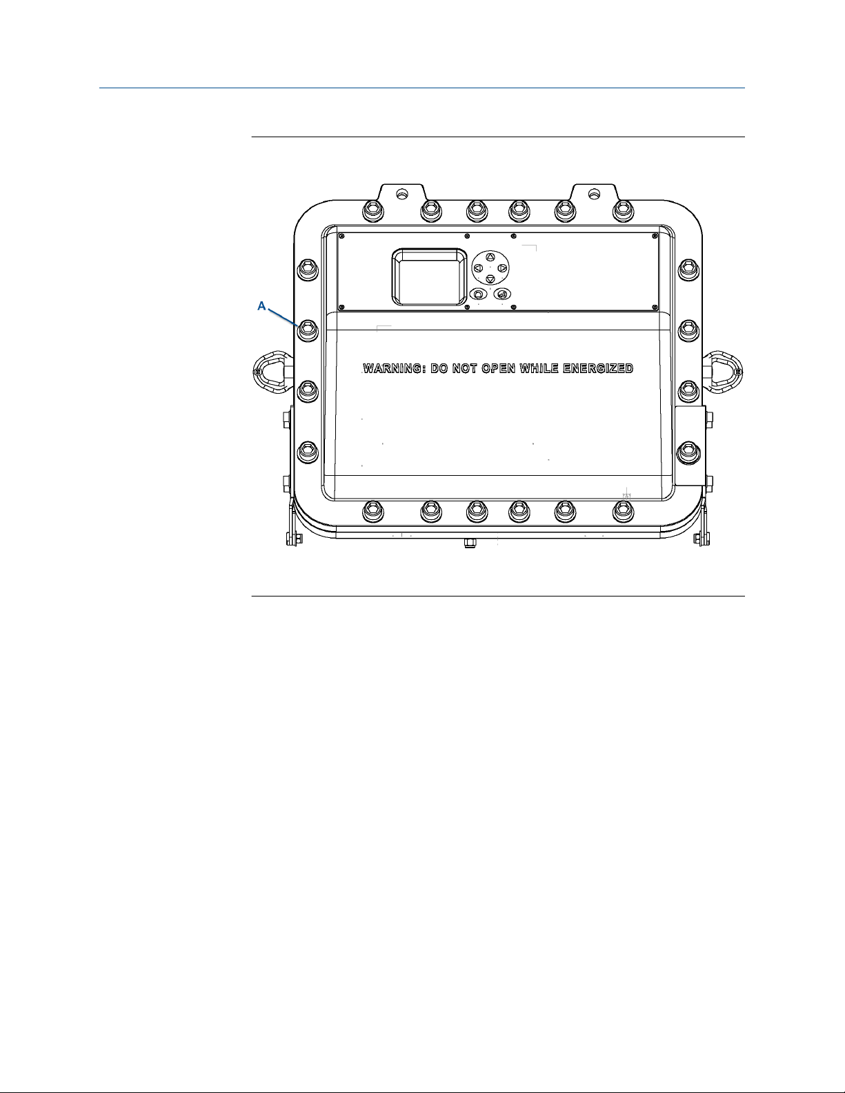
Figure 2-2: Rosemount CT5800 Housing
A. 20 off M16 captive bolts
3. Carefully lower the front enclosure to the fully open position.
40 Emerson.com/Rosemount
Page 41

Reference Manual Install
00809-0100-5800 September 2019
Figure 2-3: Enclosure Open
A. Flamepath (green highlight)
B. Seal
C. Flanges
4. Apply masking tape to the flanges, seal, and flamepath to protect them from
scratches, chipping, and other forms of damage of deformation.
CAUTION
PROTECT FLAMEPATH
Any damage to the flamepath will invalidate certification.
Protect the flamepath with masking tape.
5. Continue the installation with the power and signal cables.
See AC power safety information.
Rosemount CT5800 41
Page 42

Install
September 2019 00809-0100-5800
Reference Manual
2.3.2 AC power safety information
NOTICE
This section is in accordance with IEC 60079-0:2011 Clause 30.
This section must not be changed, amended, or removed.
WARNING
ELECTRIC SHOCK
Failure to follow instructions may cause personal injury or death.
Only qualified personnel, taking into account all applicable standards and legislative
requirements, should install the analyzer and connect the power and signal cables.
Instruments providing screw terminals for electrical connections may require working
near live parts.
The analyzer does not have power switches and is operable when connected to power.
A customer-supplied power switch or circuit breaker (complying with IEC 60947-1/ -3)
must be in the building installation. The switch has to be installed near the analyzer,
must be easily accessible, and has to be assigned as a disconnector for the analyzer.
Disconnect instruments with screw terminals from power when working at power
terminals (pull power plug or operate power switch / circuit breaker in building
installation).
The analyzer provides a protective earth terminal. To prevent electrical shock hazards,
connect the instruments to a protective earth. The instruments must be connected to
power with a three wire power cable with earth conductor. Any interruption of the
earth connector inside or outside the instrument or disconnecting the earth terminal
may cause potential electrical shock hazard.
WARNING
EXPLOSION HAZARD
In accordance with IEC 60079-0: 2011 Clause 30.
Failure to observe this warning could cause an explosion or potentially hazardous situation
which, if not avoided, may cause death or personal injury.
Only enable the purge controller bypass function during setup or maintenance and only
when the area is known to be non-hazardous.
The customer supplied circuit breaker must be in accordance with ATEX / IECEx / North
American protection concepts. The main power isolator controls the application of
electrical power to the analyzer.
Electrical protection for the instrumentation circuitry of the analyzer is provided by fuses
F1 and F2 located inside the analyzer.
42 Emerson.com/Rosemount
Page 43
Reference Manual
00809-0100-5800 September 2019
Install
Table 2-1: Electrical power requirements
Electrical supply Power consumption Voltage Fuse
Instrumentation supply
voltage
Purge supply voltage 10 W 110 to 240 Vac, 50/60 Hz ±
500 W (peak)
300 W (usual)
110 to 240 Vac, 50/60 Hz ±
10%
10%
For the electrical power wiring, use 16 AWG stranded, 3 conductor copper or tin plated
copper power wire, rated for at least 250 Vac, of the required length.
Cables must be rated for operation in ambient temperatures greater than 176 °F (80 °C).
Cables must be terminated in accordance with local electrical codes.
A switching system is not supplied with this equipment. You must supply a suitably rated
switch or circuit breaker to be included with this installation. Check the installation of the
switch for conformity in accordance with national/local regulations and standards by
inspection.
The switch or circuit breaker must be suitably located, easily reached, and identified as the
disconnection device for the analyzer.
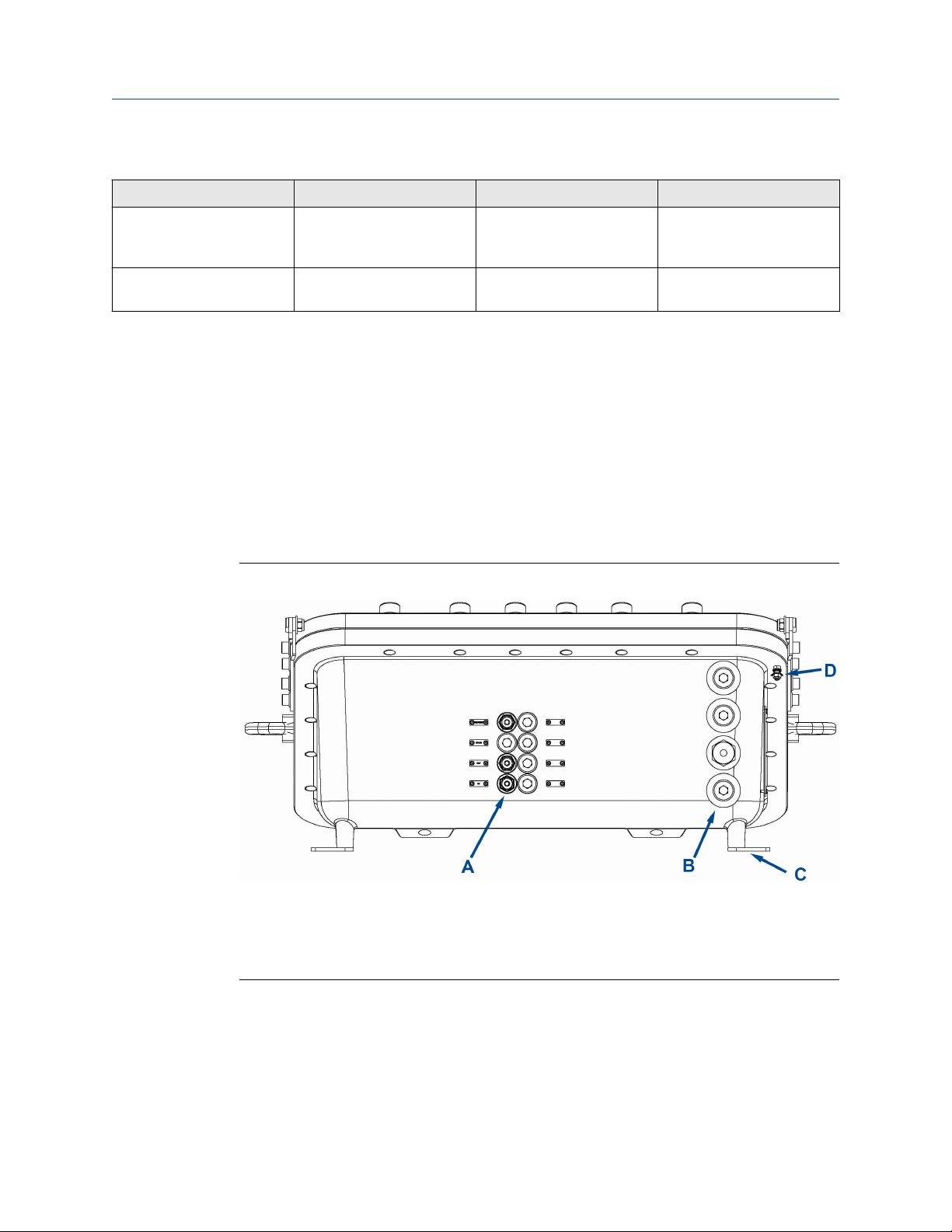
Figure 2-4: Rosemount CT5800 Bottom View: Gas Connectors and Cable Glands
3.15 A internal fuses F1 and
F2. See Connecting the
signal cables.
1 A (located in secondary
circuit breaker)
A. Gas connections (flame arrestor) (M18 x 1.5)
B. Conduit / cable entry apertures (M20 x 1.5)
C. Wall fixing line
D. Earth (ground) bond
The customer supplied circuit breaker must be in accordance with suitably certified
hazardous area Ex protection concepts. The main power isolator controls the application
of electrical power to the analyzer.
Rosemount CT5800 43
Page 44

Install Reference Manual
September 2019 00809-0100-5800
WARNING
EXPLOSION
Do not open the instrument when it is energized.
Ensure that external circuitry is disconnected or de-energized before opening the
instrument.
All cables (power and signal) must end (be connected) in either a safe (nonhazardous)
area or in a protecting enclosure (e.g., explosion-proof junction box).
WARNING
INSTALLATION USING CONDUITS
The analyzer has metric threads for installing cable entries.
Installing conduits requires metric to national pipe thread (NPT) adapters.
To be compliant with North American ordinarly location (Ordloc) and hazardous area
(Hazloc) certification, use stainless steel with captive O-ring seals.
Select a type of conduit and seals in accordance with local codes and suitable for the
site of installation.
For North American sites, do not fit seals more that 2 in. (50 mm) from the Ex d entry
point.
Unused entries are provided with plugs, secured in place with thread locking
compound.
WARNING
INSTALLATION USING CABLE GLANDS
All cable glands must be suitable certified for use in area of application (Zone/Class/
Division).
When installing the analyzer in a hydrogen environment and/or applying hydrogen to
the analyzer, do not use the standard compression type cable glands. Use suitable
compound barrier cable glands to stay compliant to EN 60079-14.
When selecting cable glands, make sure the correct diameter is selected to ensure
correct cable fit.
CAUTION
SELECT THE CORRECT TYPE OF CABLE ENTRY.
Before starting to install the analyzer, verify what type of cable entry is required at your
site of installation.
Rosemount CT5800 gas analyzers may be equipped with cable glands (e.g., regulated
for installations covered by ATEX/IEX/Ex) or may be installed with conduits (e.g., in
North America).
44 Emerson.com/Rosemount
Page 45

Reference Manual Install
00809-0100-5800 September 2019
Electrical protection for the instrumentation circuitry of the analyzer is provided by fuses
F1 and F2 located inside the analyzer.
Figure 2-5: Fuses
2.3.3
Connect power to the system through the power gland on the base of the analyzer (Figure
2-4).
Earthing/grounding the analyzer
The system must be suitably earthed / grounded using the M5 stud bonded to the rear of
the system and the connector inside with cable between 1.5 and 4 mm square.
NOTICE
This section is in accordance with IEC 60079: 2011 Clause 30. This article must not be
changed, amended, or removed.
WARNING
ELECTRIC SHOCK
In accordance with IEC 60079-0: 2011 Clause 30.
Failure to observe this warning may cause death or personal injury.
The analyzer must be earthed/grounded in accordance with national/local regulations.
Rosemount CT5800 45
Page 46

Install Reference Manual
September 2019 00809-0100-5800
Figure 2-6: Earth Bond
46 Emerson.com/Rosemount
Page 47

Reference Manual Install
00809-0100-5800 September 2019
2.3.4 Connecting the signal cables
Connect the signal cables through conduit outlets 2 and 3 as shown in the figures below.
NOTICE
This section is in accordance with IEC 60079-0: 2011 Clause 30. This section must not be
changed, amended, or removed.
The signal cables are connected to the system through conduit outlets 2 and 3 as shown in
Figure 2-7 and Figure 2-9. All signal cables are to be minimum 20 AWG tri-rated
switchgear cables. Customer supplied conduit and cables must be terminated in the
conduit outlets in accordance with local electrical codes.
Figure 2-7: Cable Glands, Conduits, and Gas Line Connections
A. Breather
B. Gas connection out (flame arrestor) (M18 x 1.5)
C. Gas connection in (flame arrestor) (M18 x 1.5)
D. Conduit / cable entry apertures (M20 x 1.5)
Figure 2-8: Signal connections
Rosemount CT5800 47
Page 48

Install Reference Manual
September 2019 00809-0100-5800
Figure 2-9: Signal cable connections
Table 2-2: Power, Digital, and Analog Connections
Terminal Function
1 System supply (L)
2 System supply (N)
3 Digital output 1
4 Digital output 2
5 Digital output 3
6 Digital output 4
7 Digital output 5
8 Digital output 6
9 Digital output 7
10 Digital output 8
11 Digital output 9
12 Digital output 10
13 Digital output 11
14 Digital output 12
15 Analog output 1
16 Analog output 2
17 Analog output 3
18 Analog output 4
19 Analog output 5
20 Analog output 6
21 Analog output 7
22 Analog output 8
23 Status output 1 (check function)
48 Emerson.com/Rosemount
Page 49

Reference Manual
00809-0100-5800 September 2019
Install
Table 2-2: Power, Digital, and Analog Connections (continued)
Terminal Function
24 Status output 2 (maintenance required)
25 Status output 3 (out of specification)
26 Status output 4 (failed)
Table 2-3: Ethernet Interface Module wiring to MOXA Ethernet Socket
Terminal Designation Color coding
1 Tx+ Orange / White
2 Tx Orange
3 Rx+ Green / White
4 Not used Blue
5 Not used Blue / White
6 Rx- Green
7 Not used Brown / White
8 Not used Brown
2.3.5 Connecting the sample supply and return lines
Sample gas supply and sample return connections are from ¼-in. (6 mm) Swagelok® type
fittings.
The analyzer has one gas input and one gas output, which are located on the base of the
analyzer (Figure 2-7).
The gas sample that is to be measured for impurities enters the instrument through the
sample gas input port.
Once the sample gas has been examined for impurities, it is expelled from the instrument
through the sample gas return port.
NOTICE
Remove the breather blanking cap and never connect anything to this port.
To avoid the risk of gas leaks, make sure that these connections are made correctly and
tightly. Both the sample gas supply pipe and the sample return pipe should be thermal
insulated.
NOTICE
The Swagelok recommendation for pipe fittings of this size is to tighten the nut finger
tight and then tighten an additional one and a quarter (1 and ¼) turns with a spanner.
The maximum gas supply pressure is 1 BarG.
Rosemount CT5800 49
Page 50

Install Reference Manual
September 2019 00809-0100-5800
The sample supply line must be heated all the way to the sample gas input port on the
analyzer to prevent condensation forming at any point in the sample supply line.
WARNING
HAZARDOUS GAS
This article is in accordance with IEC 60079-0: 2011 Clause 30.
The product stream that the analyzer is examining may be hazardous even at low
concentrations.
Take special care to ensure that the sample gas return port either returns the sample gas
to the product stream or discharges the sample gas to a location that will not cause a
hazard.
WARNING
MAINS SUPPLY CABLE
Failure to follow this warning may result in personal injury.
Make sure that the mains supply cable used is of a suitable rating for the analyzer's power
requirements.
The Ethernet connector provides an Ethernet output from the analyzer that may be used
for downloading data for failure diagnostic purposes.
The analyzer outputs the results of the gas analysis through the 4-20 mA analog outputs
and sends them to your process control center.
The status outputs provide fault indications to your process control center. Each digital
output is connected to a normally closed relay, located inside the analyzer, which will open
in response to the detection of a specific fault. The possible causes of a fault indication are:
• The sample gas concentration is outside of specification (i.e., the sample gas
concentration has exceeded the measurement range of the instrument).
• The analyzer is out of specification or has developed a fault.
WARNING
HIGH VOLTAGE
Failure to obey the wiring regulations may result in serious injury to personnel.
Voltages up to 250 Vac, 50 Hz may be present on the digital output terminals.
Install external circuits in accordance with national wiring regulations.
50 Emerson.com/Rosemount
Page 51

Reference Manual
00809-0100-5800 September 2019
Install
WARNING
ELECTRIC SHOCK
Attaching cables and wiring harnesses longer than 9.8 ft. (3 m) may cause injury to
personnel.
The analyzer passed electromagnetic compatibility (EMC) tests based on all electrical
cables and harnesses attached to it being 9.8 ft. (3 m) long.
2.4 Test connections
Before sealing the cable glands, it is vital to test the new connections in order that any
faults can be remedied before the cables are permanently sealed.
WARNING
EXPLOSION HAZARD
In accordance with IEC 60079-0: 2011 Clause 30.
Failure to observe this warning could cause an explosion or potentially hazardous situation
which, if not avoided, may cause death or personal injury.
The cable glands used in this analyzer are only suitable for use in areas with a low risk of
mechanical damage. Protect the cable glands suitably.
Temporarily seal the cable glands with a suitable sealant to allow testing.
The tests described below are a basic check to prove function, rather than a test of sensor
capability.
To start the analyzer, follow the steps in Startup procedure.
WARNING
INSTALLER RESPONSIBILITY
In accordance with IEC 60079-0: 2011 Clause 30
Failure to observe this warning could cause a potentially hazardous situation which, if not
avoided, may cause death or personal injury.
It is the installer's responsibility to connect the analyzer to a suitable alarm or shutdown
facility.
2.4.1 Testing power input cables and circuit breakers
The power input cables and circuit breakers can be tested as follows.
NOTICE
This section is in accordance with IEC 60079-0: 2011 Clause 30. This section must not be
changed, amended, or removed.
Rosemount CT5800 51
Page 52

Install Reference Manual
September 2019 00809-0100-5800
Procedure
1. Set the main circuit breaker to ON.
2. Check that the display controller lights up.
The instrument begins to power up.
52 Emerson.com/Rosemount
Page 53

Reference Manual Install
00809-0100-5800 September 2019
2.4.2 Testing temperature sensor and cell heater
The sample cell is controlled to operate at a pre-set temperature. This involves a heater
and a temperature sensor.
NOTICE
This section is in accordance with IEC 60079-0: 2011 Clause 30. This section must not be
changed, amended, or removed.
Procedure
1. Check that a temperature reading is displayed against Temperature on the display
controller as described in Operating the analyzer.
2. Leave the analyzer operating and confirm that the temperature rises until the
analysis cell reaches the pre-set operating temperature around 122 °F (50 °C).
This takes approximately 90 minutes.
2.4.3
Pressure sensor
The pressure sensor monitors the pressure in the analysis cell.
NOTICE
This section is in accordance with IEC 60079-0: 2011 Clause 30. This section must not be
changed, amended, or removed.
Procedure
1. Check that a pressure reading is displayed under Pressure on the display controller.
The reading is approximately 760 Torr at atmospheric pressure.
NOTICE
A Torr is a non SI unit of pressure, defined as 1/760 of standard atmospheric
pressure, and is equal to the fluid pressure of 1 mm of mercury.
2. If desired, cap off the gas inlet and use an external pump to evacuate the cell.
Make sure the pressure drops as expected.
Rosemount CT5800 53
Page 54

Install
September 2019 00809-0100-5800
Reference Manual
2.4.4 Testing analog output cables
Prerequisites
In order to generate a 4-20 mA output, let the analyzer warm up for 90 minutes and make
sure the analysis cell is at the correct pressure.
The 4-20 mA outputs operate when the analysis cell is between 104 and 140 °F (40 and 60
°C) and the pressure is between 180 and 220 Torr. It is not essential to flow sample gas
through the system; nitrogen or atmospheric air is adequate for this test.
Procedure
With the analyzer at operating temperature and pressure, ensure that a current between
4 mA and 20 mA is generated on each 4-20 mA output, as listed in Connecting the signal
cables.
Use a multimeter to measure the current.
2.4.5
Testing the measurement valid flag
The measurement flag is normally open contact. It is simplest to test this with a
multimeter.
With the analyzer closed and compressed air applied as described in the startup procedure
(Startup procedure) when the system is operating correctly, an open contact is created
between the two contact wires (white).
Procedure
To test the Error state, shut off the sample gas and allow the pump to reduce the cell
pressure below 180 Torr.
At this point, the contact should close and there should be no resistance between the two
white wires.
WARNING
FIRE AND EXPLOSION
In accordance with IEC 60079-0: 2011 Clause 30.
Failure to ensure the area is safe or leaving the device powered on can cause an explosion
or fire and serious injury to personnel.
Do not open the Ex d enclosure unless the area is known to be free of flammable materials
or unless all devices are switched off.
2.5 Closing the housing
After all internal connections have been made and proved/tested, close the enclosure and
secure the 20 off M16 x 45 captive screws and form A washers in accordance with the
torque sequence.
See Figure 2-11.
54 Emerson.com/Rosemount
Page 55

Reference Manual
00809-0100-5800 September 2019
Install
Procedure
1. Remove all protective covering from the flamepath and enclosure sealing gasket.
2. Inspect the seal.
If any damage is detected, stop the process immediately and report to
maintenance.
3. Clean the seal to remove any adhesive from the protective cover.
4. Inspect the flanges/flamepath for damage (i.e., scratches, chipping, and/or other
form of damage/deformation).
If any damage is detected, stop the process immediately and report to
maintenance.
5. Carefully lift the housing up and align with the rear housing.
6. Make sure that all holes are aligned. If necessary, use the two holes (Figure 2-10) to
assist alignment.
Figure 2-10: Alignment holes
A. Alignment holes
7. Insert the captive M16 bolt and engage the threads on the rear housing.
8. Refer to the torque sequence (Figure 2-11) and tighten all bolts.
Rosemount CT5800 55
Page 56

Install Reference Manual
September 2019 00809-0100-5800
WARNING
HAZARDOUS AREA PROTECTION
Failure to follow the warning will invalidate hazardous area Ex d protection.
Always use captive M16 x 45 screws and form A washers to secure the enclosure
shut.
Figure 2-11: Torque sequence
Tighten all bolts in sequence to a torque value of 18.44 ft.-lb. (25 Nm).
2.6 Commissioning
Once the sensor is fully installed as described above, commission it according to the
commissioning plan agreed on between you and Emerson.
56 Emerson.com/Rosemount
Page 57

Reference Manual Startup procedure
00809-0100-5800 September 2019
3 Startup procedure
3.1 Introduction
CAUTION
EQUIPMENT DAMAGE
Damage to the analyzer may result from a failure to follow this procedure.
Always follow the startup procedure.
The analyzer normally operates continuously. It should only be necessary to start up the
analyzer under the following circumstances:
• When the analyzer is first switched on following installation.
• Following repair or maintenance.
• When the analyzer has been switched off as part of a plant shutdown or maintenance.
3.2 Preparation for use
The analyzer must be installed and fully commissioned prior to startup.
WARNING
BURNS
Failure to allow sufficient cooling may cause serious burn injury to personnel.
Do not touch any part of the analyzer.
Assume all parts of the analyzer are hot unless it has been switched off and allowed to
cool down.
Some parts of the analyzer may be heated to 150 °F (65 °C).
Always wear proper protective equipment when handling the analyzer.
Switch off the analyzer and allow it to cool for at least two hours before fitting,
removing, or performing any maintenance.
The analysis cell is insulated against heat loss. Allow the analyzer to cool for at least
twelve hours before performing any maintenance on, or in the vicinity of, the analysis
cell.
Rosemount CT5800 57
Page 58

Startup procedure Reference Manual
September 2019 00809-0100-5800
3.3 Startup procedure
NOTICE
The gases shown in the screenshots and the measurements thereof may be different from
those shown in your particular analyzer. They indicate the functionality of the software,
which is the same regardless of the gases being measured.
NOTICE
To stop the startup procedure at any time, set the main circuit breaker to OFF.
To start up the analyzer, perform the following steps:
Procedure
1. Visually inspect the exterior of the analyzer for signs of damage, corrosion, gas
leaks, or overheating. Report anything found to the hazardous area Ex maintenance
organization.
2. Make sure that the analyzer has been correctly installed.
See Install.
3. Make sure that the enclosure is closed and all bolts are correctly torqued.
If the enclosure cannot be closed and locked, report it to the maintenance
organization and do not proceed further until the door has been repaired.
4. Make sure that the gas handling system is turned OFF.
5. Make sure that the external circuit breaker is set to OFF.
6. Visually examine the gas ports to make sure that the sample supply line and the
sample return line are correctly attached to the analyzer.
If necessary, refer to Replacing the gas input and output lines.
7. Visually check that the electrical connections have been made to the instrument.
8. Set the main circuit breaker to ON, which applies main power to the instrument.
The analyzer begins its automatic startup. The control PC that forms part of the
instrument is configured to automatically load the necessary gas sensor software
and configuration files. The startup sequence commences automatically under
software control.
After a few seconds, the Gas Sensor Main screen (Figure 3-1) appears on the display
controller. If it does not, report the fault to the maintenance organization.
58 Emerson.com/Rosemount
Page 59

Reference Manual Startup procedure
00809-0100-5800 September 2019
Figure 3-1: Gas Sensor Main Screen
9. Start up the system for returning the sample gas.
10. Start up the gas handling system that conditions the sample gas before it is fed into
the analyzer. Allow the analyzer to warm up in accordance with the Detailed system
specifications before the sample gas supply is turned on.
At the end of the startup procedure, the gas measurements initially appear as 0.00 ppm
until the first readings are taken. After a few seconds, the initial gas concentrations will be
displayed.
Rosemount CT5800 59
Page 60

Startup procedure Reference Manual
September 2019 00809-0100-5800
60 Emerson.com/Rosemount
Page 61

Reference Manual Operating the analyzer
00809-0100-5800 September 2019
4 Operating the analyzer
4.1 Introduction
This chapter describes the controls, displays, and indicators on the Rosemount CT5800
and how to use the display controller located on the front panel of the instrument.
4.2 Normal operation
The analyzer is designed for long term continuous operation, and therefore its normal
state is to be switched on and performing gas measurements. The analyzer is usually only
switched off for maintenance. The shutdown procedure used to switch off the analyzer is
described in Shutdown procedure.
Provided that the Startup procedure has been followed, the analyzer does not require any
human intervention during normal operation other than occasional calibration checks as
described in Gas calibration.
During normal operation, either the Gas Sensor Main screen (Figure 4-1) or the Pressure
and Temperature screen (Figure 4-2) is shown on the display controller. To toggle
between these two screens, press .
Figure 4-1: Gas Sensor Main Screen
Rosemount CT5800 61
Page 62
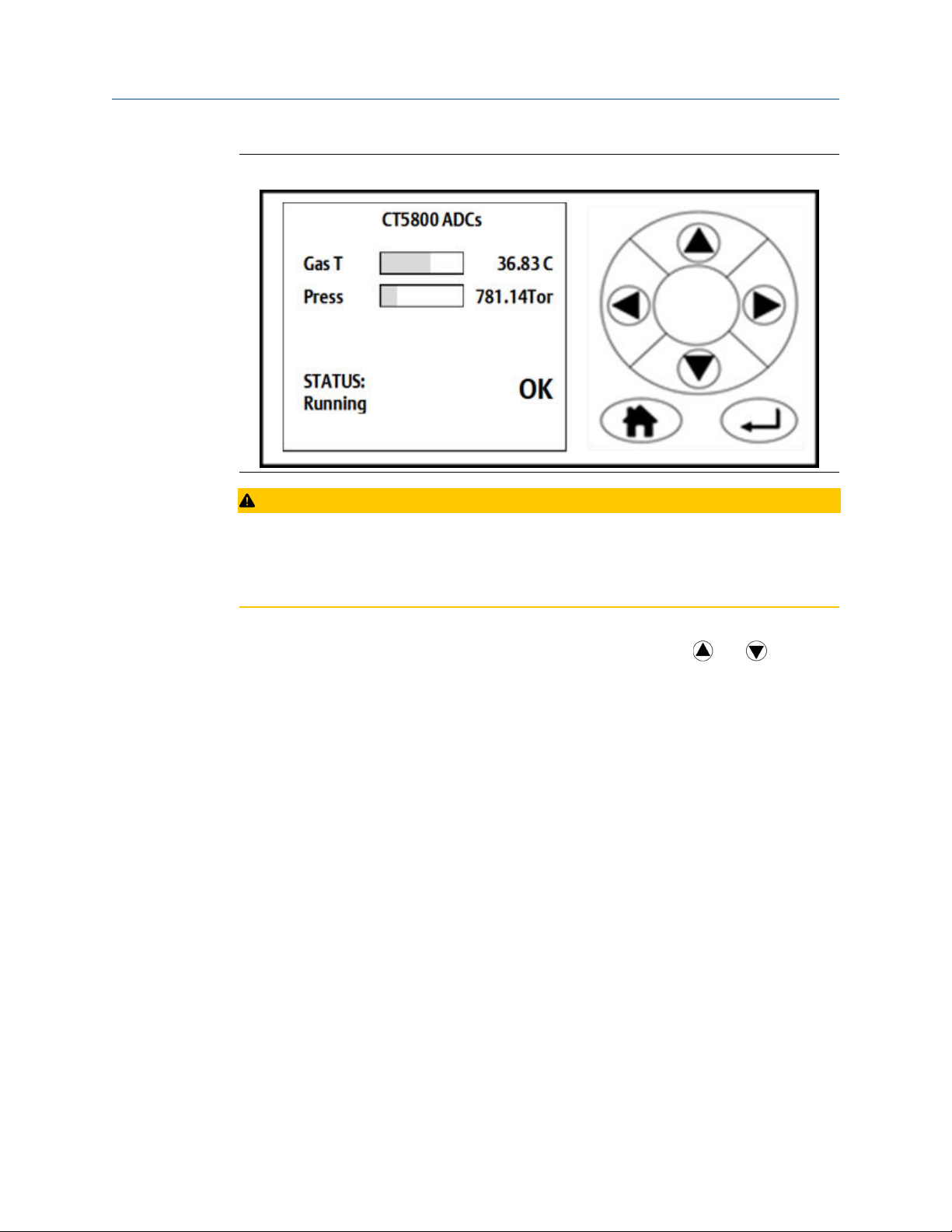
Operating the analyzer Reference Manual
September 2019 00809-0100-5800
Figure 4-2: Pressure and Temperature Screen
CAUTION
UNSERVICEABLE EQUIPMENT
If the pressure and temperature measurements are out of tolerance, refer to
Troubleshooting and diagnostics.
On both the Gas Sensor Main screen and the Pressure and Temperature screen, if the
analyzer makes more measurements than can fit on the display, use
down the list.
4.3 Front panel controls and indicators
The analyzer is configured from the display controller located on the front panel.
and to scroll
62 Emerson.com/Rosemount
Page 63

Reference Manual Operating the analyzer
00809-0100-5800 September 2019
Figure 4-3: Front Panel Display Controller
NOTICE
On/Off circuit breakers
There are no On/Off switches on the analyzer. The application of electrical power to the
analyzer is controlled through an external circuit breaker.
The circuit breaker is a simple two-pole on/off circuit breaker that must be set to On to
permit the safe operation of the analyzer.
Rosemount CT5800 63
Page 64

Operating the analyzer Reference Manual
September 2019 00809-0100-5800
4.4 Display controller
Figure 4-4: Front Panel Display Controller
A. LCD display
B. Navigation buttons
You can control the analyzer through six navigation buttons (Figure 4-4, B) on the display
controller.
The LCD display (A) can be used to display:
• Gas concentration measurements obtained
• Operating temperature and pressure
• Help screens
• Step-by-step calibration
• Diagnostics
The navigation buttons (B) are configured to perform different functions according to
which software screen is shown on the LCD display.
Table 4-1: Display Controller Navigation Button Functions
Button Description
Normally used to scroll up. Referred to as UP.
Normally used to scroll down. Referred to as DOWN.
Normally used to select. Also accesses the Main Menu from the Home
screen. Referred to as RIGHT.
Used to go back to the previous screen. No function from the Home
screen. Referred to as LEFT.
Used to access the context sensitive Help pages. Referred to as HOME.
64 Emerson.com/Rosemount
Page 65

Reference Manual Operating the analyzer
00809-0100-5800 September 2019
Table 4-1: Display Controller Navigation Button Functions (continued)
Button Description
Generally used to select an alternative function. Also allows you to toggle
between gas and physical measurements from the Home screen.
Referred to as ENTER.
The analyzer employs Intelligent Device Management which enables self-monitoring and
diagnostics. This ensures that operators are made aware of malfunctions so they can take
appropriate action. Table 4-2 defines the symbols that may be displayed.
Table 4-2: Diagnostic symbols
System running
Maintenance required: still valid output signal
Out of specification: signal out of the specified range
Indicates the analyzer is performing a calibration or validation or that the
software has been deliberately stopped.
Failure: non-valid output signal
4.5 Gas Sensor Main screen
When the analyzer is switched on, at the end of the start-up procedure, the Gas Sensor
Main screen (Figure 4-5) appears.
The Gas Sensor Main screen is the screen that is normally displayed.
NOTICE
The gas concentrations shown in the following screenshots may be different from those
shown in your particular analyzer. The screenshots indicate the functionality of the
software, which is the same regardless of the gases or gas concentrations being measured.
Rosemount CT5800 65
Page 66

Operating the analyzer Reference Manual
September 2019 00809-0100-5800
Figure 4-5: Gas Sensor Main Screen
The Gas Sensor Main screen displays the gas concentration measurements obtained by
the analyzer. In the example shown in Figure 4-5, the gases carbon dioxide (CO2), methane
(CH4), carbon monoxide (CO), and water (H2O) are being measured; for each gas, the
concentration detected is in parts per million (ppm).
4.6
At the end of the start-up procedure, the gas measurements initially appear as 0.00 ppm
until the first readings are taken. After a few seconds, the initial gas concentrations are
displayed.
The Gas Sensor Main screen also shows the status of the analyzer. In the example shown
in Figure 4-5, the analyzer is Running and OK (i.e., no faults have been identified).
If a fault is identified, ? is displayed; if maintenance is required,
To access other screens through the Main menu, press
is a link between the Gas Sensor Main screen (Figure 4-5) and the Pressure and
Temperature screen (Figure 4-6). Press
is a link to the Help system. Press to go to a Help screen (described in Help
system).
On the Gas Sensor Main screen, has no function when the analyzer is operating
correctly. If, however, the software detects a fault, an error message is displayed. Press
to get further information on the error.
to toggle between the two screens.
. (Refer to Figure 4-5).
is displayed.
Pressure and Temperature screen
The Pressure and Temperature screen (Figure 4-6) shows pressure and temperature
measurements taken inside the analyzer.
66 Emerson.com/Rosemount
Page 67

Reference Manual Operating the analyzer
00809-0100-5800 September 2019
Figure 4-6: Pressure and Temperature Screen
NOTICE
A Torr is a non-SI unit of pressure defined as 1/760 of standard atmospheric pressure and is
equal to the fluid pressure of 1 mm of mercury.
4.7 Help system
The analyzer software includes a context-sensitive help system. Press , which is
available on most of the software screens, to open the help system.
The help system contains a number of different Help screens, each conveying a different
message. As the help system is context-sensitive, the Help screen that appears is the one
that is most appropriate to the software function engaged when was pressed. Figure
4-7 shows an example of a help screen.
Rosemount CT5800 67
Page 68

Operating the analyzer Reference Manual
September 2019 00809-0100-5800
Figure 4-7: Example of a Help Screen
4.8 Main menu
To access the Main menu (Figure 4-8) , press on either the Gas Sensor Main screen
(Figure 4-5) or the Pressure and Temperature screen (Figure 4-6). The Main menu
( Figure 4-8) options are:
• DIAGNOSTICS: Displays various parameters used in the internal calculations and
compares desired and actual parameters, for example, the analysis cell pressure and
temperature. The diagnostics routines and screens are used to perform fault diagnosis.
• FAULTS: Takes you to a screen that lists any faults affecting the analyzer. This option is
used as part of the failure diagnosis procedures.
• GAS SERVICE: Allows you to check the sensor readings against a known gas source
(verification) or, if necessary, to calibrate the analyzer against that known gas source
(calibration).
• DATA SERVICE: Takes you to a screen that allows data to be downloaded from the
instrument. The downloaded data is used to diagnose faults.
• SYSTEM: Takes you to a screen that allows the analyzer to be shut down or displays the
software versions.
68 Emerson.com/Rosemount
Page 69

Reference Manual Operating the analyzer
00809-0100-5800 September 2019
Figure 4-8: Main Menu
4.9 BACK button
On most of the software screens, the top left-hand button is configured as a BACK
button. Press BACK to return to the previous screen.
Rosemount CT5800 69
Page 70

Operating the analyzer Reference Manual
September 2019 00809-0100-5800
70 Emerson.com/Rosemount
Page 71

Reference Manual Verifying gas concentrations
00809-0100-5800 September 2019
5 Verifying gas concentrations
5.1 Verification
Verification flows the known gas concentration through the analyzer and gives you a
display of the measurement, the cylinder value, and the difference between the two. You
can use verification to confirm that the analyzer is within tolerance. If it is out of tolerance,
perform a calibration (see Calibration).
5.1.1 Zero verification
Zero verification confirms that when no sample gas is flowing through the analyzer, the
gas concentrations measured by the instrument are zero. To zero verify, compare the
analyzer measurements to a known sample gas using the following procedure:
Procedure
1. Refer to Figure 4-8. Using and , select GAS SERVICE.
2. Press .
The Select gas screen (Figure 5-1) opens.
Figure 5-1: Select gas Screen
3. Use and to move the cursor until the gas that you wish to zero verify is
selected. Press .
The Select Type screen (Figure 5-2) opens.
Rosemount CT5800 71
Page 72
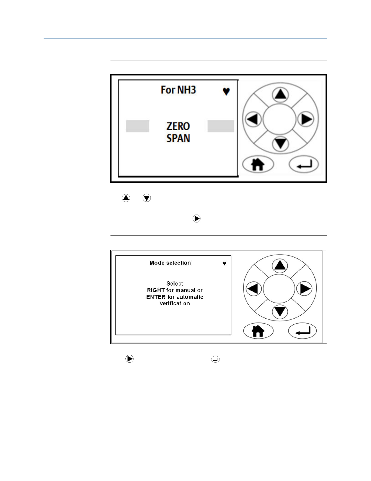
Verifying gas concentrations Reference Manual
September 2019 00809-0100-5800
Figure 5-2: Select Type Screen
4. Use and to move the cursor until the ZERO verification option is selected, as
shown in Figure 5-2.
5. To perform a verification, press
.
The Manual/Automatic screen (Figure 5-3) opens.
Figure 5-3: Manual/Automatic Screen
6. Press for manual verification. Press for automatic verification.
The Verify Zero screen (Figure 5-4) opens.
72 Emerson.com/Rosemount
Page 73

Reference Manual Verifying gas concentrations
00809-0100-5800 September 2019
Figure 5-4: Verify Zero Screen
7. Allow the concentrations to stabilize and wait for two minutes after stabilization.
This screen gives a reading of the concentration of the selected gas that is present
as an impurity in the nitrogen calibration gas, as measured by the instrument. In the
example (Figure 5-4), the gas being measured is NH3 (ammonia), and the
instrument has detected a concentration of 0.40 ppm.
8. If the reading is within tolerance, no further action is required. Press to end the
zero verification process.
The display controller proceeds to the Result screen (Figure 5-5).
Figure 5-5: Result Screen
9. If the reading is outside tolerance, you need to zero calibrate the analyzer.
Refer to Zero calibration.
10. In either case, press to return to the Calibration / Verification Complete screen
(Figure 5-6).
Rosemount CT5800 73
Page 74

Verifying gas concentrations Reference Manual
September 2019 00809-0100-5800
Figure 5-6: Calibration / Verification Complete Screen
11. To perform a zero verification for another gas, press .
The software returns to the Select gas screen (Figure 5-1).
12. Repeat the actions in steps Step 3 through Step 10 for the next gas.
5.1.2
13. To perform a span verification, press . Then follow the span verification
procedure in Span verification.
14. If you are finished verifying the analyzer, press
The software returns to the Gas Sensor Main screen.
.
Span verification
To verify the span gas concentrations measured by the analyzer when reference gas is
flowing:
Prerequisites
Run the analyzer at a stable temperature for at least thirty minutes before starting this
procedure.
Procedure
1. Use a certified reference gas cylinder as the source of the span verification gas.
2. Ensure that a pressure regulator is connected to the reference gas bottle.
3. Connect a hose from the reference gas bottle, through a T-piece, to the sample
supply port on the rear panel of the analyzer.
4. Connect an excess flow line to the unused port on the T-piece and route the excess
flow line to a suitable extractor.
5. On the display controller, browse to the Main menu as described in Main menu.
6. Using and , select GAS SERVICE (Figure 5-7).
74 Emerson.com/Rosemount
Page 75

Reference Manual Verifying gas concentrations
00809-0100-5800 September 2019
Figure 5-7: Main menu
7. Press .
The Select gas screen (Figure 5-8) opens.
Figure 5-8: Select gas Screen
8. Use and to move the cursor until the gas that you wish to span verify is
selected. Press .
The Select Type screen (Figure 5-9) opens.
Rosemount CT5800 75
Page 76
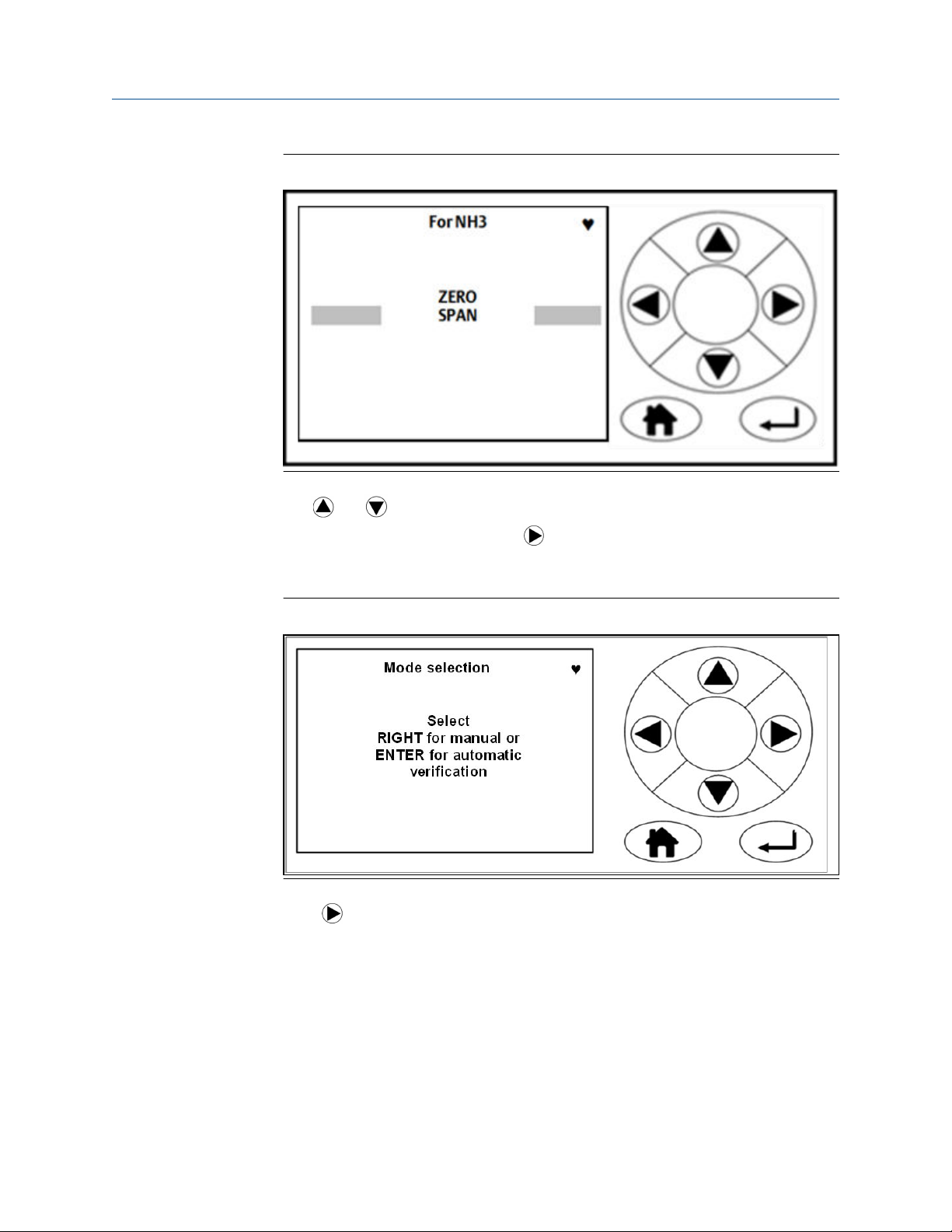
Verifying gas concentrations Reference Manual
September 2019 00809-0100-5800
Figure 5-9: Select Type screen
9. Use and until the SPAN verification option is selected, as shown in Figure
5-9. To perform a verification, press .
The Mode selection screen opens (Figure 5-10) for manual or automatic
verification.
Figure 5-10: Mode selection Screen
10. Press for manual verification.
The Span input screen (Figure 5-11) opens.
76 Emerson.com/Rosemount
Page 77

Reference Manual Verifying gas concentrations
00809-0100-5800 September 2019
Figure 5-11: Span input Screen
11. Use and to highlight each digit in turn; then use and to increase or
decrease the value until the concentration displayed matches the cylinder you are
using.
NOTICE
The cylinder concentration must be entered in ppm.
12. Press to proceed to the next step.
The Verify span screen (Figure 5-12) opens.
Figure 5-12: Verify span Screen
13. Press to cancel the manual verification.
14. Press to finish.
Rosemount CT5800 77
Page 78

Verifying gas concentrations Reference Manual
September 2019 00809-0100-5800
15. Repeat steps Step 5 through Step 9.
16. Press for automatic verification.
This opens the valve (where applicable) and flows the span gas.
17. Allow the concentrations to stabilize and wait for two minutes after stabilization.
This screen gives a reading of the concentration of the selected gas that is present,
as measured by the instrument. In the example shown in Figure 5-12, the gas being
measured is NH3 (ammonia), and the instrument has detected a concentration of
2000.29 ppm.
18. If the reading is within tolerance, no further action is required. Press to end the
span verification process.
The display controller proceeds to the Result screen (Figure 5-13).
Figure 5-13: Result Screen
19. If the reading is outside tolerance, the span calibrate the analyzer.
Refer to Span calibration.
20. Press to return to the screen shown in Figure 5-14.
78 Emerson.com/Rosemount
Page 79

Reference Manual Verifying gas concentrations
00809-0100-5800 September 2019
Figure 5-14: Calibration / Verification Screen
21. If you wish to perform a span for another gas, press .
The software returns to the Select gas screen (Figure 5-1).
22. Repeat steps Step 8 through Step 16 for the next gas.
23. If you wish to zero verify, press . Then follow the zero verification procedure in
Zero verification.
24. If you are finished verifying the analyzer, press .
The software returns to the Gas Sensor Main screen (Figure 4-5).
The span verification procedure is now complete.
Rosemount CT5800 79
Page 80

Verifying gas concentrations Reference Manual
September 2019 00809-0100-5800
80 Emerson.com/Rosemount
Page 81

Reference Manual Gas calibration
00809-0100-5800 September 2019
6 Gas calibration
6.1 Required tools
The gas concentrations measured by the analyzer can be validated against a known
sample gas or calibrated to match it by using the following gas calibration procedure.
To calibrate the analyzer, you need the following items:
• Nitrogen gas of "instrument gas" purity for use as a zero calibration gas
• Suitable span calibration gases for each gas measured
• Gas bottle pressure regulators
• Interconnecting hoses to connect the gas bottles to the analyzer
• A T-piece and excess flow line
NOTICE
In the case of gases such as H2O, where it is not normally possible to obtain calibrated gas
cylinders, it will usually be measured by the same laser as some other gas. Validating the
other gases measured by the analyzer (particularly any which are measured by the same
laser as H2O) can demonstrate that the system is functioning correctly, meaning there is
no need to calibrate the water measurement directly.
If you need to calibrate (e.g., for legal requirements), you can use a water vapor generator
to supply a known concentration of water vapor.
6.2 Main menu
Access the calibration functions through the Main menu (Figure 6-1). To get to the Main
menu, press MENU on either the Gas Sensor Main screen or the Pressure and
Temperature screen, as described in Main menu.
Rosemount CT5800 81
Page 82

Gas calibration Reference Manual
September 2019 00809-0100-5800
Figure 6-1: Main menu
Use the Main menu to access the software routines and screens that are used for
calibration and maintenance. Five options are presented (Figure 6-1). For more
information about the options on the Main menu, see Main menu.
On the Main menu, use and to scroll between the menu options.
When the option you want is highlighted (GAS SERVICE is the example shown in Figure
6-1), press to go to the first screen of that software routine.
6.3 Calibration
Calibration flows the known cylinder gas through the analyzer and then adjusts the
readout until the measurement matches the cylinder. The analyzer then applies this
adjustment to all measurements until the next calibration. There are two circumstances in
which you may want to calibrate.
1. After you verify gas concentrations (see Verifying gas concentrations) and find that
the analyzer readings are outside of tolerance
2. At regular intervals, such as once a day or once a shift
6.3.1
Zero calibration
Zero calibration is calibrating the analyzer so that when no sample gas is flowing through
it, the gas concentrations measured by the analyzer are zero. To zero calibrate, calibrate
the analyzer measurements against a known sample gas using the following procedure:
Prerequisites
Run the analyzer at a stable temperature for at least thirty minutes prior to commencing
this procedure.
Use nitrogen gas of "instrument gas" purity as the zero calibration gas.
82 Emerson.com/Rosemount
Page 83

Reference Manual Gas calibration
00809-0100-5800 September 2019
Procedure
1. Make sure that a pressure regulator is connected to the nitrogen gas bottle.
2. Connect a hose from the nitrogen gas bottle through a T-piece to the sample supply
port on the rear of the analyzer. Connect an excess flow line to the unused port on
the T-piece and route the excess flow line to a suitable extractor.
3. On the display controller of the analyzer, browse to the Main menu as described in
Main menu.
Figure 6-2: Main Menu
4. Using and , select GAS SERVICE.
5. Press .
The Select gas screen (Figure 6-3) opens.
Figure 6-3: Select gas Screen
6. Use and to move the cursor until the gas that you wish to zero calibrate is
selected. Press .
Rosemount CT5800 83
Page 84

Gas calibration Reference Manual
September 2019 00809-0100-5800
The Select Type screen (Figure 6-4) opens.
Figure 6-4: Select Type Screen
7. Use and to move the cursor until the ZERO calibration option is selected (see
Figure 6-4).
8. To calibrate, press .
The Mode selection screen (Figure 6-5) opens.
Figure 6-5: Mode selection Screen
9. Press for manual calibration. Press for automatic calibration.
10. Press to confirm.
The Result screen (Figure 6-6) displays.
84 Emerson.com/Rosemount
Page 85

Reference Manual Gas calibration
00809-0100-5800 September 2019
Figure 6-6: Result Screen
11. After the required flush time (dependent on analyzer configuration), the top line on
the screen changes from Calibrate zero to Result.
This shows the zero calibration is complete.
6.3.2
12. Press to finish the process.
13. Press to display the Calibrate gas screen (Figure 6-4) and perform a span
calibration on the same gas (see Span calibration).
Span calibration
Span calibrate to verify the span gas concentrations measured by the analyzer when
reference gas is flowing and, if necessary, calibrate them against the known reference gas.
Prerequisites
Run the analyzer at a stable temperature for at least 30 minutes prior to commencing this
procedure. Startup takes 90 minutes to achieve the required temperature.
Procedure
1. Use a certified reference gas cylinder as the source of the span calibration gas.
2. Make sure that a pressure regulator is connected to the reference gas bottle.
3. Connect a hose from the reference gas bottle, through a T-piece, to the sample
supply port on the rear panel of the analyzer. Connect an excess flow line to the
unused port on the T-piece and route the excess flow line to a suitable extractor.
4. On the display controller of the analyzer, browse to the Main menu as described in
Main menu.
5. Refer to Figure 6-2. Using and , select GAS SERVICE.
6. Press .
The Select gas screen (Figure 6-7) opens.
Rosemount CT5800 85
Page 86

Gas calibration Reference Manual
September 2019 00809-0100-5800
Figure 6-7: Select gas Screen
7. Use and to move the cursor until the gas that you wish to span calibrate is
highlighted by the cursor. Press .
The Select type screen (Figure 6-8) opens.
Figure 6-8: Select Type Screen
8. Use and to move the cursor until SPAN is selected (Figure 6-8). To calibrate,
press .
The Mode selection screen (Figure 6-9) opens.
86 Emerson.com/Rosemount
Page 87

Reference Manual Gas calibration
00809-0100-5800 September 2019
Figure 6-9: Mode selection Screen
9. Press to perform a manual calibration.
The Span input screen (Figure 6-10) opens.
Figure 6-10: Span input Screen
10. Use and to highlight each digit in turn; then use and to increase or
decrease the value until the concentration displayed matches the cylinder you are
using. Press
to proceed to the next step.
NOTICE
Enter the cylinder concentration in ppm.
The Begin Calibrate span screen (Figure 6-11) opens.
Rosemount CT5800 87
Page 88

Gas calibration Reference Manual
September 2019 00809-0100-5800
Figure 6-11: Begin Calibrate span Screen
11. Press to confirm. The Calibrate span screen Figure 6-12 opens.
Figure 6-12: Calibrate span Result Screen
12. Allow the concentrations to stabilize and wait for two minutes after stabilization.
This screen gives a reading of the concentration of the selected gas that is present,
as measured by the instrument. In Figure 6-12, the gas being measured is NH
3
(ammonia), and the instrument has detected a concentration of 119.41 ppm (vol).
13. If the reading is now within tolerance, no further action is required. Press or
to abort the span calibration process.
14. If the reading is outside tolerance, press ENTER.
The analyzer returns to its factory-set calibration. Allow a minute to ensure the
readings are stable.
15. If the reading is now within tolerance, no further action is required. Press or
to abort the calibration process.
16. If the calibration of the analyzer remains outside of tolerance, you can adjust the
calibration by pressing .
This brings up a Calibrate screen (Figure 6-12).
17. To proceed with the automatic re-calibration, press .
88 Emerson.com/Rosemount
Page 89

Reference Manual Gas calibration
00809-0100-5800 September 2019
The automatic re-calibration of the instrument's span calibration starts, and the
offset shown on the screen (in Figure 6-13 it is 0.997) is applied to the instrument.
Press or to abort the calibration process.
When the calibration or verification is complete, the screen shown in Figure 6-13 is
displayed.
Figure 6-13: Calibrate Complete Screen
18. If you wish to perform a span calibration for another gas, press .
The software returns to the Select gas screen (Figure 6-7). Repeat steps Step 7
through Step 17 for the next gas.
19. If you are finished calibrating the analyzer, press .
The software returns to the Main menu shown in Figure 6-2.
Rosemount CT5800 89
Page 90

Gas calibration Reference Manual
September 2019 00809-0100-5800
90 Emerson.com/Rosemount
Page 91

Reference Manual Troubleshooting and diagnostics
00809-0100-5800 September 2019
7 Troubleshooting and diagnostics
7.1 Troubleshooting, repairs, and failure diagnostics
To diagnose failures in the analyzer, you must interpret system fault messages shown on
the LCD display, visually examine the data, perform failure diagnostic tests, and download
performance data and send that data to Emerson for analysis.
In the failure diagnosis procedures, all controls and indicators are on the analyzer unless
otherwise indicated.
Observe and obey all safety precautions when performing preventative maintenance on
the analyzer.
Important
The troubleshooting and failure diagnosis procedures described in this chapter assume
that any host equipment provided by you is fully functional. Always make sure that the
host equipment is fully serviceable before performing failure diagnosis on the analyzer.
Failure diagnosis, repair, and maintenance must only be performed by:
• Maintenance engineers who have the necessary skills, training, and hazardous area Ex
training where applicable and who have been authorized to perform maintenance on
the analyzer.
• Emerson customer care engineers.
In all the cases described in this chapter, maintenance personnel must perform the repairs
by directly replacing the faulty item with a known serviceable spare part supplied by
Emerson. All other items must be repaired or replaced by the manufacturer.
NOTICE
As a general principle, if any optical component other than the cell assembly and the laser
module is unserviceable, the analyzer must be repaired by Emerson. Repair, replacement,
and alignment of the optical components require the use of special optical test/calibration
equipment and procedures.
DANGER
FLAMMABLE SUBSTANCES
This article is in accordance with IEC 60079-0: 2011 Clause 30.
Some parts of the analyzer may reach temperatures of 150 °F (65 °C) and may present an
igintion source. A fire may result if this precaution is not observed.
Exercise care when using oil, paint, cleaning rags, and other flammable substances
near the analyzer.
Always assume that the interior of an analyzer is hot unless it has been switched off and
allowed to cool down.
Rosemount CT5800 91
Page 92

Troubleshooting and diagnostics Reference Manual
September 2019 00809-0100-5800
DANGER
ELECTRIC SHOCK
This article is in accordance with IEC 60079-0: 2011 Clause 30.
Death or personal injury may result if this is not observed.
The analyzer uses mains voltage that is dangerous to life. Make sure that the circuit
breakers are set to OFF and tagged off before opening the front cover.
WARNING
HEAVY ITEM
The analyzer weighs 176.4 lb. (80 kg). Failure to properly handle the analyzer may cause
injury to personnel.
Use a minimum of two people when lifting and transporting the equipment.
Wear suitable protective gloves and protective footwear.
WARNING
TRANSPORTATION HAZARD
Failure to secure the equipment may cause a break-away and injure personnel.
When preparing the analyzer for transport by air, road, or rail, safeguard it against
movement or break-away during transport by securely strapping it in place. Use suitable
fasteners for the weight of the analyzer.
WARNING
INSTALLATION HAZARD
Failure to properly install the equipment may cause serious injury to personnel.
Make sure that the wall unit the analyzer is mounted on is solid, stable, and of a suitable
material to hold the weight of the analyzer.
Do not mount the analyzer on stud or partition walls.
92 Emerson.com/Rosemount
Page 93

Reference Manual Troubleshooting and diagnostics
00809-0100-5800 September 2019
WARNING
FIRE AND EXPLOSION
Failure to observe this precaution may cause death, personal injury, and/or damage to
property.
Do not open the Ex d enclosure of the analyzer unless the atmosphere in the area is known
to be below the ignitable concentration of combustible gases or materials.
WARNING
OPTICAL RADIATION EXPOSURE HAZARD
The analyzer contains lasers. Opening the analyzer and attempting to perform
adjustments or procedures other than those specified in this manual may result in
hazardous optical radiation exposure.
Failure to follow the correct procedures may cause damage to the eye.
The Rosemount CT5800 is Class 1. The beams are fully enclosed, and there is no access to
the laser beams while the product is in operation or during maintenance. Do not look at
the lasers with any kind of magnifier or optical measuring device.
The use of control or adjustments or performance of procedures other than those
specified herein may result in hazardous radiation exposure.
In accordance with USA 21 CFR 1040, the Rosemount CT5800 has warning labels at
appropriate positions.
The locations of the safety labels in the analyzer are specified in Safety and system
labels and annotation.
There are three types of lasers that may be included in the Rosemount CT5800: Quantum
Cascade Lasers (QCLs), Interband Cascade Lasers (ICLs), and Tunable Diode Lasers (TDLs).
The characteristics of the lasers contained within are given in the table below.
Parameter
Operation mode Pulsed Pulsed Pulsed
Lasers per system 1 - 6 1 - 6 1 - 6 Maximum of 6
Wavelength 4 -10 µm 2 - 5 µm 760 nm
Power < 5 mW < 5 mW < 5 mW
Pulse duration < 1 µs 1 µs < 5 µs
QCL ICL TDL Comments
lasers per system
Pulse repetition
frequency
Duty cycle < 5% < 5% < 5%
Rosemount CT5800 93
< 100 kHz < 100 kHz < 100 kHz
Page 94

Troubleshooting and diagnostics Reference Manual
September 2019 00809-0100-5800
WARNING
BURNS
Some parts of the analyzer may be heated to 150 °F (65 °C). Failure to allow sufficient
cooling may cause serious burn injury to personnel.
Do not touch any part of the analyzer.
Assume all parts of the analyzer are hot unless it has been switched off and allowed to
cool down.
Always wear proper protective equipment when handling the analyzer.
Switch off the analyzer and allow it to cool for at least two hours before fitting,
removing, or performing any maintenance.
The analysis cell is insulated against heat loss. Allow the analyzer to cool for at least 12
hours before performing any maintenance on, or in the vicinity of, the analysis cell.
If burns occur, seek immediate medical treatment.
WARNING
HAZARDOUS SUBSTANCES
Gas handling components within the analyzer will contain particulate matter residue from
the sample gases. Over the life of the analyzer, the concentration of the particulate matter
will become enriched within the gas handling components.
When performing repairs or maintenance on the analyzer:
Handle used gas handling components with extreme caution.
Avoid direct skin contact with used gas handling components.
Do not smoke, drink, or eat in the work area.
Wear goggles or eye shields.
Wear a suitable face mask to protect against inhalation of particulate matter.
Do not wet fingers, eyes, or any exposed skin.
Pack used gas handling components for disposal in sealed packaging and label them
Contaminated.
Dispose of contaminated items as hazardous material according to the applicable local,
national, or international health and safety regulations and pollution regulations.
7.2 Using the Built-in-Test (BIT) fault diagnostics
The analyzer has a limited BIT diagnostics function.
Prerequisites
The BIT function can be used to perform failure diagnosis of some functions in situations
where there is a fault other than a complete failure of the equipment. Use the display
controller mounted on the front panel to access and control the BIT.
Procedure
1. You can see the STATUS information from either the Gas Sensor Main screen (see
Figure 7-1) or the Pressure and Temperature screen (see Figure 7-2)
94 Emerson.com/Rosemount
Page 95

Reference Manual Troubleshooting and diagnostics
00809-0100-5800 September 2019
Figure 7-1: Gas Sensor Main Screen
Figure 7-2: Pressure and Temperature Screen
2. When the analyzer is running correctly, the STATUS displays Running and OK (see
Figure 7-1).
3. If a fault is detected the STATUS display in the bottom left-hand corner of the
screen changes from OK to a flashing .
Rosemount CT5800 95
Page 96

Troubleshooting and diagnostics Reference Manual
September 2019 00809-0100-5800
Figure 7-3: Fault Status - Analyzer Running Screen
If the analyzer stops the STATUS changes to Stopped, and OK changes to a ?.
Figure 7-4: Fault Status - Analyzer Stopped
4. From either the Gas sensor main screen (see Figure 7-1) or the Pressure and
Temperature screen (see Figure 7-2), press to go to the Main menu.
5. Press and to scroll to the Faults screen.
96 Emerson.com/Rosemount
Page 97

Reference Manual Troubleshooting and diagnostics
00809-0100-5800 September 2019
Figure 7-5: Main menu - FAULTS Screen
If the BIT has not identified any faults, the central area of the Faults screen is blank.
Figure 7-6: Faults Screen - No Faults Detected
If the BIT has identified faults, the display controller indicates the fault. The precise
data displayed varies depending upon where the fault has occurred in the analyzer.
Rosemount CT5800 97
Page 98

Troubleshooting and diagnostics Reference Manual
September 2019 00809-0100-5800
Figure 7-7: Faults Detected Screen
6. Press and to list the fault listed.
7. Press to display the Fault diagnostic information screen.
Figure 7-8: Cell heater Temperature Out of Range
8. Examine the data shown on the Fault screen to determine if the suspect component
has failed or is operating outside of its correct parameters. If you do not have the
necessary information to determine if the suspect component is faulty, contact
your local Customer Care representative.
9.
From the Main menu, press
and to scroll to DIAGNOSTICS.
98 Emerson.com/Rosemount
Page 99

Reference Manual Troubleshooting and diagnostics
00809-0100-5800 September 2019
Figure 7-9: Main menu
The Diagnostics screen lists those main components of the analyzer where
problems can be diagnosed using the BIT system. The Diagnostics screen also
enables you to check on the status and, where appropriate, the values of any of the
listed components.
Figure 7-10: Diagnostics Menu
10. Press and to scroll to the component for further troubleshooting.
11. Press to display the component's diagnostic information. See Figure 7-11 for a
diagnostics example for Laser 1.
Rosemount CT5800 99
Page 100

Troubleshooting and diagnostics Reference Manual
September 2019 00809-0100-5800
Figure 7-11: Laser 1 Component Diagnostics Screen
The parameters data displayed varies depending upon which component was
selected for diagnosis.
12. Examine the data shown on the Component Diagnostic screen to determine if the
suspect component has failed or is operating outside of its correct parameters. If
you do not have the necessary information to determine if the suspect component
is faulty, contact your local Customer Care representative.
7.3 Faults menu
The Faults menu displays an example list of faults affecting the analyzer that have been
identified by the BIT. If no faults have been identified by the BIT, the central area of the
Faults menu is blank.
Figure 7-12: Fault screen (no information)
However, if the BIT identifies a fault, the display shows what the fault is. See Figure 7-13.
100 Emerson.com/Rosemount
 Loading...