

Emerson Rosemount CT5100 Ex Quick Start Manual
Quick Start Guide
D-7010-0055, Rev C
Rosemount™ CT5100 (Ex) Continuous Gas
Analyzer
August 2018

Preface
Published by EmersonTM.
All possible care has been taken in the preparation of this publication, but EmersonTM and its agents and distributors accept no
liability for any inaccuracies that may be found. This manual reflects the state of the product at the issure date below, but further
enhancements while in service may mean that the manual does not reflect your particular system. This quick start guide reflects
the state of the product at the issue date below, but further enhancements while in service may mean that the manual does not
reflect your particular system.
Emerson reserves the right to make changes without notice both to this publication and the products which it describes.
Document number: D-7010-0055
Rev C, August 2018
©
Emerson 2018. All rights reserved.
No part of this publication may be reproduced, stored in a retrieval system, or transmitted in any form or by any means electronic,
mechanical, photocopying, recording, or otherwise without the express prior written permission of the copyright holder.
If you require additional technical assistance, request help from (cascade.support@emerson.com) or Emerson distribution
partners.
General inquiries should be sent to cascade.support@emerson.com.
All trademarks used within this document are the property of their respective owners.
Rosemount™ CT5100(Ex) Preliminary Information
This section details important user information for the Rosemount™ CT5100(Ex) Continuous Gas Analyzer.
This article is in accordance with IEC 60079-0: 2011 Clause 30.
This article must not be changed amended or removed.
Important
Users must read, understand and comply with the following information before proceeding.
All users, installers, operators and maintainers must be familiar with operating the analyzer. To install, start up, operate, maintain
and service the analyzer in a safe manner, it is MANDATORY to read all additional instruction manuals shipped with the analyzer.
The following instruction manual(s) are available and / or referenced within this manual:
• Quick Start Guide D-7010-0055
All instructions must be saved for future use. Contact your local service center or sales office when missing documents.
Authorized Personnel
In-depth specialist knowledge is an absolute requirement for working with and on the analyzer. Personnel installing, operating,
servicing and maintaining the analyzer must be instructed, trained, qualified and authorized personnel of the operating company
for hazardous areas and the manufacturer. It is the responsibility of the operating company to:
• train staff
• observe safety regulations
• follow the safety instructions and procedures in the product manual.
Operators must:
• have been trained
• have read and understand all relevant sections of the product manual before commencing work
• know the safety mechanisms and regulations
WARNING
To avoid explosions, loss of life, personal injury and damage to this equipment and on-site property, do not install, operate,
maintain or service this analyzer before reading and understanding this instruction manual and receiving appropriate training.
2

Safety Precautions
Operators, maintenance personnel, and authorized users must observe the following safety precautions and warnings.
DANGER
ELECTRIC SHOCK
In accordance with IEC 60079-0: 2011 Clause 30.
The analyzer operates using mains voltage, which may cause death or serious injury to personnel. Make sure that the circuit
breakers are set to Off and locked out and tagged out off before removing the top cover or opening the front cover. The analyzer
must be earthed.
Death, personal injury, and/or damage to persons and/or property may result if this is not observed.
DANGER
EXPLOSION HAZARD
In accordance with IEC 60079-0: 2011 Clause 30.
The sample gas in the system must be vented to prevent fire or explosion during maintenance and to prevent damage to the
analyzer during start-up.
The sample gas in the pipes leading to the analyzer must be purged for a minimum of 2 minutes 30 seconds at a minimum flow
rate of 280 l/m at 1.5 ± 0.5 bar to prevent hazards to personnel during maintenance.
You must purge the sample gas in accordance with the safe working procedures for this site.
Allow the analyzer and the system for returning the sample gas to run for five minutes to allow any sample gas in the analyzer to
be returned to the exhaust.
Failure to observe this precaution will cause death, personal injury, and/or damage to persons
DANGER
FLAMMABLE SUBSTANCES
Some parts of the analyzer may reach temperatures of °C ( °F) and may present an ignition source. Exercise care when using oil,
paint, cleaning rags, or other flammable substances near the analyzer. A fire may result if this precaution is not observed. The
interior of a analyzer is always hot unless it has been switched off and allowed to cool down.
WARNING
TRANSPORTATION HAZARD
Handle the analyzer with caution during unpacking, installation, maintenance, and transport to prevent crushing of hands, feet, or
other body parts.
The analyzer weighs 55 kg (121 lb) and should always be lifted and moved using suitable lifting/moving equipment. Wear suitable
protective gloves and protective footwear. When preparing the analyzer for transport by air, road, or rail, safeguard the analyzer
against movement or break-away during transport by securely strapping it in place.
WARNING
FIRE AND EXPLOSION
In accordance with IEC 60079-0: 2011 Clause 30.
The electrical compartment of the analyzer must not be opened unless the atmosphere in the area is known to be below the
ignitable concentration of combustible gases or materials, or unless all equipment within the protected enclosure is de-energized
in accordance with NFPA 496 and ISO60079-1 / 2 and 28.
Failure to observe this warning could cause an explosion or potentially hazardous situation, which if not avoided, may cause death,
personal injury, and/or damage to persons and/or property.
3

WARNING
FIRE, BURN, AND OPTICAL RADIATION EXPOSURE HAZARD
In accordance with IEC 60079-0: 2011 Clause 30.
Operators and service personnel do not have access to the laser/electrics or upper cell compartments for general maintenance or
service.
Electrical shock, thermal burns, or loss of vision may occur.
Failure to observe this warning could cause an explosion or potentially hazardous situation, which if not avoided, may cause death,
personal injury, and/or damage to persons and/or property.
WARNING
COMBUSTIBLE GASES
In accordance with IEC 60079-0: 2011 Clause 30.
The protective gas supply valve must be kept open unless the atmosphere in the area is known to be below the ignitable
concentration of combustible gases or materials, or unless all equipment within the protected enclosure is de-energized in
accordance with NFPA 496.
Failure to observe this warning could cause an explosion or potentially hazardous situation, which if not avoided, may cause death,
personal injury, and/or damage to persons and/or property.
WARNING
EXPLOSION HAZARD
In accordance with IEC 60079-0: 2011 Clause 30.
Always lock out the gas handling system when shutting down the analyzer. Unauthorized performance on the analyzer or its
associated pipes/hoses may result in highly flammable gas being released, causing fire or explosion. Failure to lock out gas
handling system may cause death.
WARNING
BURNS
Some parts of the analyzer may be heated to 165 °C (329 °F). To prevent burns, do not touch any of the hot parts. All parts of a
analyzer are always hot unless it has been switched off and allowed to cool down.
Before fitting, removing, or performing any maintenance on the analyzer, make sure that it has been switched off and allowed to
cool for at least two hours. Before performing any maintenance on, or in the vicinity of, the analysis cell, allow the analyzer to cool
for at least twelve hours as the analysis cell is insulated against heat loss.
When handling the analyzer, always use suitable protective gloves.
Personal injury and/or damage to property may result if these precautions are not observed. These precautions are particularly
important when working at heights. If a burn is received, seek medical treatment immediately.
WARNING
LASER
The Rosemount™ CT5100(Ex) contains lasers. Opening the Rosemount™ CT5100(Ex) and attempting to perform adjustments or
procedures other than those specified in this manual may result in hazardous optical radiation exposure.
All lasers used within the Rosemount™ CT5100(Ex) are Class 1. The emitted laser light is invisible (mid-infrared) and the combined
laser powers are sufficiently low at the first accessible aperture that the unprotected eye will not be damaged. This class is eye safe
under all operating conditions.
It is, however, possible to cause damage to the eye through not following correct procedures. Do not look at the laser with any
kind of magnifier or optical measuring device.
4
WARNING
HAZARDOUS SUBSTANCES
The analyzer may contain hazardous substances. Always handle the analyzer assemblies and components with extreme caution.
Wear personal protective equipment (PPE) when handling the equipment.
Gas handling components within the analyzer contain particulate matter residue from the sample gases. Over the life of the
analyzer, the concentration of particulate matter will become enriched within the gas handling components. When performing
repairs and maintenance on the analyzer:
• Handle used gas handling components with extreme caution.
• Avoid direct skin contact with used gas handling components.
• Do not smoke, drink, or eat in the work area.
• Wear goggles or eye shields.
• Wear a suitable face mask to protect against inhalation of particulate matter.
• Do not wet fingers, eyes, or any exposed skin.
• Pack used gas handling components for disposal in sealed packaging and label them Contaminated.
• Dispose of contaminated items as hazardous material in accordance with applicable local, national, or international health
and safety regulations and pollution regulations.
Failure to observe this warning could cause a potentially hazardous situation, which if not avoided, may cause death, personal
injury, and/or damage to persons and/or property.
WARNING
OPTICAL RADIATION EXPOSURE HAZARD
In accordance with IEC 60079-0: 2011 Clause 30.
The
Rosemount™ CT5100(Ex) contains lasers. Opening the Rosemount™ CT5100(Ex) and attempting to perform adjustments and
procedures other than those specified in this manual may result in hazardous optical radiation exposure.
All lasers used within the Rosemount™ CT5100(Ex) are Class 1. The combined laser powers are sufficiently low at the first
accessible aperture that the unprotected eye will not be damaged. This class is eye safe under all operating conditions.
Failure to follow the correct procedures may cause damage to the eye. Do not look at the lasers with any kind of magnifier or
optical measuring device.
There are three types of laser that may be included in the Rosemount™ CT5100(Ex) : Quantum Cascade Lasers (QCLs), Interband
Cascade Lasers (ICLs), and diode lasers. The lasers within the Rosemount™ CT5100(Ex) are Class 1. The characteristics of the lasers
contained within the Rosemount™ CT5100(Ex) are given in the table below.
Parameter QCL ICL Diode Comment
Operation mode Pulsed Pulsed Pulsed
Lasers per system 1 - 6 1-6 1-6 Maximum of 6 lasers per system
Wavelength 4 - 10 µm 2- 5 µm Approximately 760 nm
Power < 5 mW < 5 mW < 5 mW Combined power of QCL at first accessible
Pulse duration < 1 µs < 1 µs < 5 µs
Pulse repetition
frequency
Duty cycle < 5% < 5% < 25%
The combined power of the QCL, ICL, and diode lasers at the first accessible aperture is < 9.62 mW.
The Rosemount™ CT5100(Ex) has warning labels in appropriate positions according to USA 21 CFR 1040.10. The location of laser
safety labels on the Rosemount™ CT5100(Ex) is specified in Safety and system labels and annotation.
The use of controls or adjustments or performance of procedures other than those specified herein may result in hazardous
radiation exposure.
< 100 kHz < 100 kHz < 100 kHz
aperture: < 9.62mW
5

WARNING
HAZARDOUS GAS
In accordance with IEC 60079-0: 2011 Clause 30.
The product stream that the analyzer is examining may be hazardous even at low concentrations. Special care should therefore be
taken to ensure that the sample gas return port either returns the sample gas to the product stream or discharges the sample gas
to a location that will not cause a hazard.
WARNING
HIGH PRESSURE GAS AND AIR
The calibration gas supply and compressed air supply operate at a pressure that can cause injury, e.g., damage to eyes and skin
punctures from debris blown by the high pressure gas or compressed air. Always lock off or tag out the calibration gas supply and
compressed air supply when shutting down the analyzer.
WARNING
HEAVY INSTRUMENT
The analyzer weighs 55 kg (121 lb.) and is designed to be wall mounted.
It must be moved in accordance with local safety regulations, however, Emerson recommend that a minimum of two people using
suitable tools for transportation and lifting are employed.
Use suitable fasteners for the weight of the unit. Make sure the wall the unit is mounted on is solid, stable and of a suitable
material to support the weight.
Failure to observe this warning and or follow safety instruction could cause an explosion or potentially hazardous situation, which
if not avoided, could result in death or serious injury.
WARNING
EXPLOSION HAZARD / ELECTRIC SHOCK HAZARD
In accordance with IEC 60079-0: 2011 Clause 30.
Only trained, qualified personnel may install and connect power and signal cables. The installation/connection must be in
accordance with all legislative requirements and applicable standards.
Failure to follow may cause warranty invalidation, property damage and/or personal injury or death.
Installation of the analyzer is subject to qualified personnel only, familiar with the resulting potential risks.
Analyzers providing screw terminals for electrical connections may require working near live part. Failure to observe this warning
and or follow safety instruction c could cause an explosion or potentially hazardous situation, which if not avoided, could result in
death or serious injury.
WARNING
HIGH PRESSURE HAZARD
In accordance with IEC 60079-0: 2011 Clause 30.
The maximum inlet purge gas pressure at the inlet valve must not exceed 690 kPa (6.9 bar). Higher pressure may damage the
analyzer enclosure in case of failure of the inlet valve.
Failure to observe this warning could cause a potentially hazardous situation which if not avoided, could result in death or serious
injury.
6

WARNING
EXPLOSIONS HAZARD DUE TO ELECTROSTATIC DISCHARGE
In accordance with IEC 60079-0: 2011 Clause 30.
In the event of a sudden discharge from electrostatically charged devices or individuals, there is a risk of an explosion. Take
suitable measures to ensure that no electrostatic discharge can build up in the explosions risk area.
Clean the device surface by gently wiping it with a damp or antistatic cloth only.
Failure to observe this warning and or follow safety instruction c could cause an explosion or potentially hazardous situation,
which if not avoided, could result in death or serious injury.
WARNING
EXPLOSION HAZARD
In accordance with IEC 60079-0: 2011 Clause 30.
After the enclosure has been open, do not restore power until the enclosure has been purged for a minimum of 2 minutes 30
seconds at a minimum flow rate of 280 l/m at 1.5 ± 0.5 bar.
Failure to observe this warning could cause an explosion or potentially hazardous situation, which if not avoided, may cause death,
personal injury, and/or damage to persons and/or property.
WARNING
POSSIBLE EXPLOSION HAZARD
In accordance with IEC 60079-0: 2011 Clause 30.
DO NOT operate the analyzer with doors or covers open.
Refer to local regulations as this may require a competent hot work supervisor to issue a hot work permit.
Failure to observe this warning and or follow safety instruction could cause an explosion or potentially hazardous situation, which
if not avoided, could result in death or serious injury.
WARNING
HAZARD BY WRONG INPUT VOLTAGE
In accordance with IEC 60079-0: 2011 Clause 30.
Applying a rated voltage other than specified on the analyzer´s nameplate label may cause an explosion, injury or damage to the
installation.
Pressurized analyzers for hazardous locations DO NOT provide wide range power supplies.
This type of analyzer is always setup for a specific rated input voltage, see nameplate label.
Ensure the voltage at site of installation meets the rated analyzer input voltage.
Failure to observe this warning could cause an explosion or potentially hazardous situation, which if not avoided, may cause death,
personal injury, and/or damage to persons and/or property.
WARNING
EXPLOSION HAZARD
In accordance with IEC 60079-0: 2011 Clause 30.
When the analyzer is out of order or if the pressurization unit shuts off due to a failure, all inputs and outputs connected to
external equipment MUST be shut off.
This will ensure that no hazardous voltages are present within the analyzer enclosure when not pressurized.
Failure to observe this warning could cause an explosion or potentially hazardous situation, which if not avoided, may cause death,
personal injury, and/or damage to persons and/or property.
7

WARNING
EXPLOSION HAZARD
In accordance with IEC 60079-0: 2011 Clause 30.
The start-up procedure is only to be carried out by properly trained personnel who understand the contents of all applicable
manuals and related instructions.
Failure to observe this warning could cause an explosion or potentially hazardous situation, which if not avoided, may cause death,
personal injury, and/or damage to persons and/or property.
WARNING
EXPLOSION HAZARD
In accordance with IEC 60079-0: 2011 Clause 30.
During the pre-purge phase all inputs and outputs connected to external equipment MUST be shut off.
This will ensure that no hazardous voltages are present within the analyzer enclosure when not pressurized.
Note: the internal backup battery is still connected and associated circuitry remains powered.
Failure to observe this warning could cause an explosion or potentially hazardous situation, which if not avoided, may cause death,
personal injury, and/or damage to persons and/or property.
WARNING
EXPLOSION HAZARD
In accordance with IEC 60079-0: 2011 Clause 30.
Do not open while an explosive atmosphere may be present.
Failure to observe this warning could cause an explosion or potentially hazardous situation, which if not avoided, may cause death,
personal injury, and/or damage to persons and/or property.
WARNING
EXPLOSION HAZARD
In accordance with IEC 60079-0: 2011 Clause 30.
Do not keep operating the analyzer if the enclosure shows permanent deformations after performing the overpressure test.
Failure to observe this warning could cause an explosion or potentially hazardous situation, which if not avoided, may cause death,
personal injury, and/or damage to persons and/or property.
WARNING
EXPLOSION HAZARD
In accordance with IEC 60079-0: 2011 Clause 30.
Use only replacement parts and components authorized by Emerson.
All replacement parts and components must be certified and approved for use in hazardous areas.
Failure to comply will void certification and may cause an explosion or potentially hazardous situation, which if not avoided, may
cause death, personal injury, and/or damage to persons and/or property.
8

WARNING
EXPLOSION HAZARD BY BATTERY
In accordance with IEC 60079-0: 2011 Clause 30.
The analyzer contains a battery for data backup purposes.
Under normal operating conditions there is no need to replace the battery during the analyzer life time. Battery replacement
MUST only be conducted by Rosemount™ Customer Care personnel. It is NOT a customer serviceable item.
Failure to observe this warning could cause an explosion or potentially hazardous situation, which if not avoided, may cause death,
personal injury, and/or damage to persons and/or property.
WARNING
LOOSE ITEMS
Do not place any loose items on top of the system or inside the compartments when doors / covers are open.
Make sure that all loose items, tools and equipment are removed from compartments before closing doors and covers.
Failure to observe this warning could cause a potentially hazardous situation that if not avoided could result in death or serious
injury.
WARNING
MAINTENANCE / MODIFICATIONS
In accordance with IEC 60079-0: 2011 Clause 30.
On completion of any maintenance and or modifications make sure:
• All tools and equipment are removed
• No contamination (water/dust) is in the compartments
• Wipe clean
• Vents are clear and not obstructed
• Verify that system is in a safe state for operation
Failure to observe this warning could cause a potentially hazardous situation that if not avoided could result in death or serious
injury.
WARNING
TRANSPORTATION HAZARD
Use safety approved lifting equipment. The user must ensure the equipment is tested, meets the lifting ratings for the weight of
the equipment, and is in good operational condition.
Failure to verify equipment meets the lifting ratings and is in good operational condition may cause injury to personnel or damage
the analyzer.
CAUTION
EQUIPMENT DAMAGE
Do not power up or try to operate the analyzer unless it is physically secure and all electrical and pneumatic connections to the
analyzer are in place.
Before commencing the start-up process, it is important to ensure that electrical power, sample gas handling facilities, and any
calibration gases that are required are available to the analyzer.
Failure to perform pre-system start-up checks may cause damage to equipment.
CAUTION
EQUIPMENT DAMAGE
Always follow the start-up procedure. Damage to the analyzer may result from a failure to follow this procedure.
9

CAUTION
EQUIPMENT DAMAGE
Always follow the shutdown procedure. Damage to the analyzer may result from a failure to follow this procedure.
CAUTION
LASER RADIATION
Attempting to perform adjustments other than those specified in this manual may result in hazardous optical radiation exposure
which could cause damage to the eye.
Do not look at the lasers with any kind of magnifier or optical measuring device.
CAUTION
UNSERVICEABLE EQUIPMENT
If the pressure and temperature screen does not display measurements similar to those shown in Gas sensor main screen and
Pressure and Temperature screen..
CAUTION
EMC
This is a Class A product. In a domestic environment, this product may cause radio interference, in which case the user may be
required to take adequate measures.
NOTICE
EMC
As a general principle, if any optical component other than the cell assembly, the laser modules and the detectors is unserviceable
the analyzer must be repaired by Emerson. This is because the repair, replacement and alignment of the optical components
requires the use of special optical test/calibration equipment and procedures.
Some faults can only be repaired by Emerson. Where an item is unserviceable, and no replacement procedure is given in this
manual, then the fault must be repaired by Emerson.
Safety and system labels and annotation
The labels and annotation applied to the analyzer are specified in the table below.
Label type Example Location
Identification label (including Emerson.com/RosemountGasAnalysis Front panel
Laser radiation CAUTION label
Laser module identification label On each laser module housing
Earth identification label Back plate
10

Quick Start Guide Contents
D-7010-0055 August 2018
Contents
Chapter 1 Introduction ............................................................................................................... 13
1.1 Site selection ................................................................................................................................. 13
1.2 Unpacking the Rosemount™ CT5100 (Ex) Continuous Gas Analyzer ..............................................
1.3 Qualified personnel ....................................................................................................................... 16
1.4 Mounting the analyzer .................................................................................................................. 18
1.5 Software version ........................................................................................................................... 22
Chapter 2 Install ......................................................................................................................... 23
2.1 System overview ........................................................................................................................... 23
2.2 Gas inputs and outputs ................................................................................................................. 25
2.3 Connecting the electrical/electronic inputs and outputs ............................................................... 26
Chapter 3 Operating the analyzer ............................................................................................... 35
3.1 Front panel controls and indicators ............................................................................................... 35
3.2 Display controller .......................................................................................................................... 38
3.3 Gas sensor main screen ................................................................................................................. 39
3.4 Pressure and Temperature screen ................................................................................................. 41
3.5 Help system .................................................................................................................................. 42
3.6 Main menu .................................................................................................................................... 43
3.7 BACK button ................................................................................................................................. 43
14
Chapter 4 Start-up procedure ..................................................................................................... 45
4.1 Introduction .................................................................................................................................. 45
4.2 Preparation for use ........................................................................................................................ 45
4.3 Opening the electrical compartment door .................................................................................... 46
4.4 Start-up ........................................................................................................................................ 47
Chapter 5 Calibrating the analyzer .............................................................................................. 59
5.1 Required tools ............................................................................................................................... 59
5.2 Main Menu Calibration Routines ................................................................................................... 60
5.3 Closing the electrical compartment door ...................................................................................... 77
Appendix A Engineering Drawings ................................................................................................ 79
A.1 Engineering drawings ................................................................................................................... 79
Quick Start Guide 11

Contents Quick Start Guide
August 2018 D-7010-0055
12 Rosemount ™ CT5100 Ex

Quick Start Guide Introduction
D-7010-0055 August 2018
1 Introduction
1.1 Site selection
The Rosemount™ CT5100(Ex) has a T3 temperature classification. The user must ensure
that no combustible gas concentrations will be present, whether on a continual or
occasional basis, which have an ignition temperature below the T3 rating of the analyzer.
DANGER
FIRE AND EXPLOSION
The electrical compartment of the must not be opened unless the atmosphere in the area
is known to be below the ignitable concentration of combustible gases or materials, or
unless all equipment within the protected enclosure is de-energized in accordance with
NFPA496.
Death, personal injury and/or damage to persons and/or property may result if this is not
observed.
DANGER
ELECTRIC SHOCK
Rosemount™ CT5100(Ex) operates using mains voltage, which may cause death or serious
injury to personnel. Make sure that the circuit breakers are set to Off and locked out and
tagged out off before removing the top cover or opening the front cover.
Failure to observe this precaution will cause death, personal injury, and/or damage to
persons and/or property.
The Rosemount™ CT5100(Ex) is intended to be installed in a suitable Division 2 Shelter to
protect it from the elements.
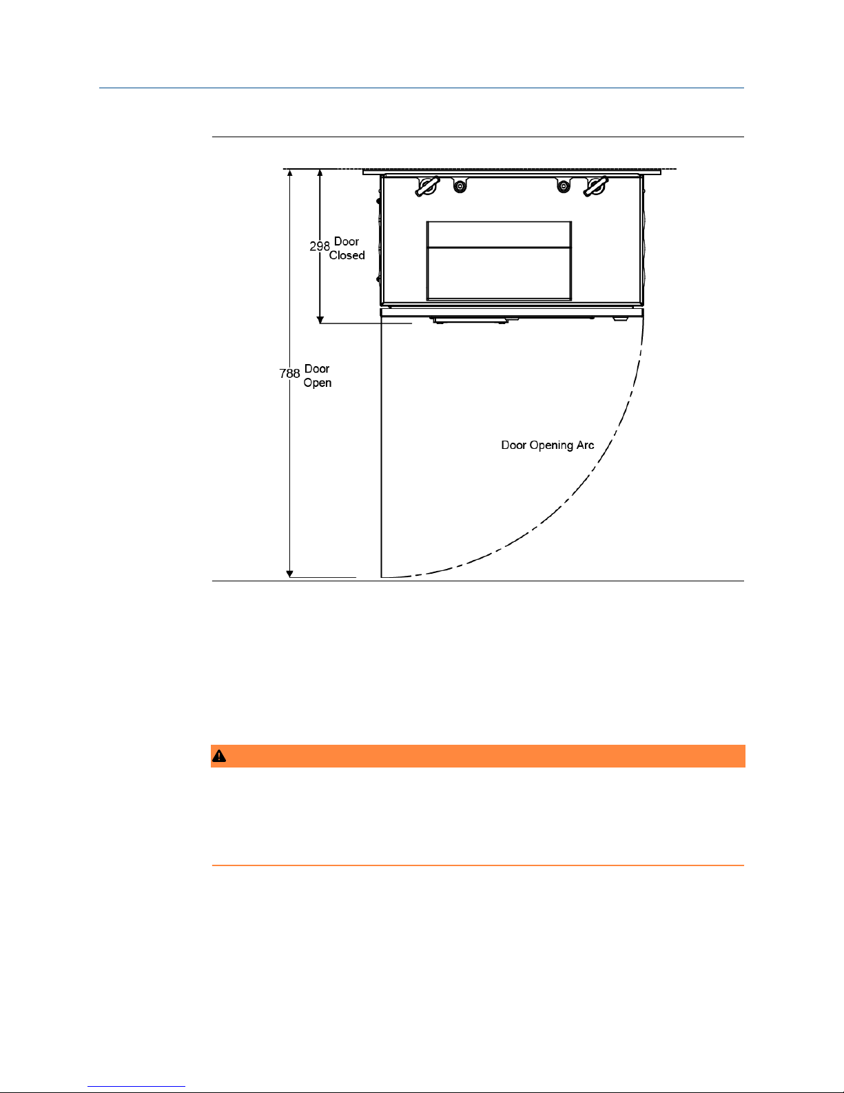
Sufficient space should be provided around the analyzer to allow the maintenance and
servicing of the unit.
Quick Start Guide 13
Introduction Quick Start Guide
August 2018 D-7010-0055
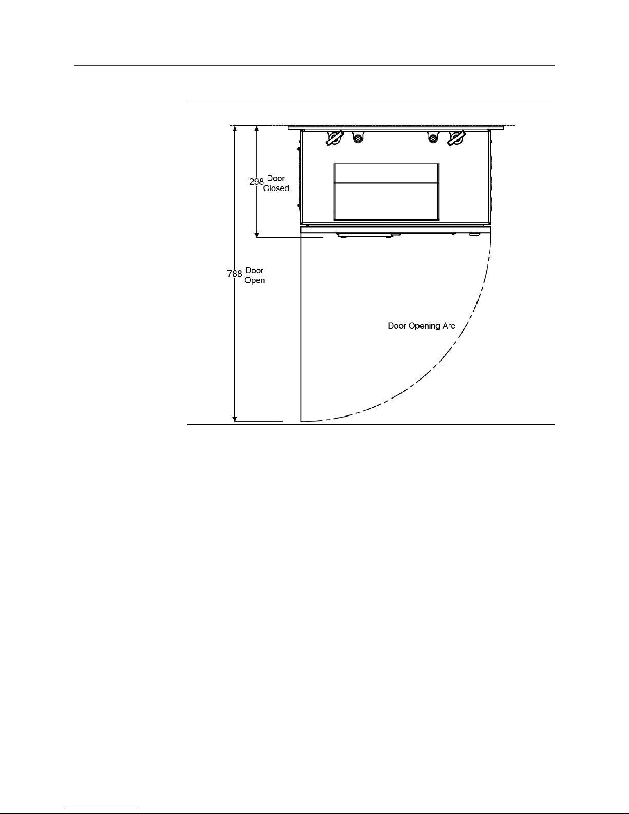
Figure 1-1: Clearance with Door Open
1.2 Unpacking the Rosemount™ CT5100 (Ex)
Continuous Gas Analyzer
This procedure requires a minimum of two people to safely remove the equipment from
the shipping container.
Prerequisites
WARNING
LIFTING HAZARD
The equipment weighs 55 kg (121 lbs.) and requires a two man lift. Local health and safety
procedures must be followed.
Failure to follow these procedures may result in serious personal injury.
14 Rosemount ™ CT5100 Ex

Quick Start Guide Introduction
D-7010-0055 August 2018
WARNING
TRANSPORTATION HAZARD
Use safety approved lifting equipment. The user must ensure the equipment is tested,
meets the lifting ratings for the weight of the equipment, and is in good operational
condition.
Failure to verify equipment meets the lifting ratings and is in good operational condition
may cause injury to personnel or damage the equipment.
Procedure
1.
Visually inspect the exterior of the analyzer for signs of damage, corrosion, gas
leaks, or signs of previously overheating.
2. Report anything found to the maintenance organization.
3. Attach suitably rated and test lifting slings to the safety engineered lifting eye bolts
mounted on top of the analyzer.
4. One person should carefully guide the equipment from the horizontal to vertical
position while the other person lifts the equipment.
5. Use safety approved and tested lifting equipment to remove the analyzer from the
shipping container.
Quick Start Guide 15
Introduction Quick Start Guide
August 2018 D-7010-0055
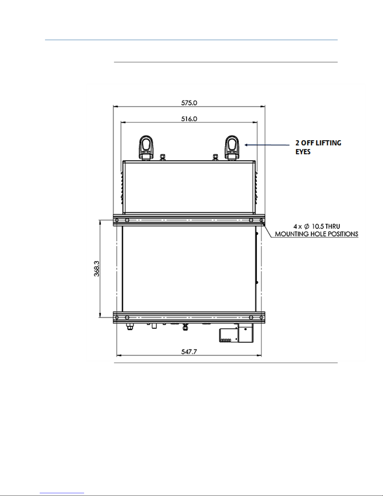
Figure 1-2: Rosemount CT5100 (Ex)- Rear View Showing Lifting Eyes and 4 off
Ø10.5 Mounting Holes
6. Place the Rosemount CT5100 (Ex) on a solid, level surface and prepare to wall
mount the analyzer.
1.3 Qualified personnel
In-depth specialist knowledge is an absolute requirement for working with and on the
analyzer. Personnel installing, operating, servicing and maintaining the analyzer must be
instructed, trained, qualified and authorized personnel of the operating company for
hazardous areas and the manufacturer.
16 Rosemount ™ CT5100 Ex

Quick Start Guide Introduction
D-7010-0055 August 2018
It is the operating company's responsibility to:
• Train staff.
• Observe safety regulations.
• Follow the safety instructions and procedures in the product manual.
Operators must:
• Be trained.
• Read and understand all relevant sections of the product manual before commencing
work.
• Know the safety mechanisms and regulations.
WARNING
To avoid explosions, loss of life, personal injury, and damage to this equipment and on-site
property, do not install, operate, maintain, or service this analyzer before reading and
understanding this instruction manual and receiving appropriate training.
Important
All users must read this page before proceeding!
Emerson™ (Rosemount™ ) designs, manufactures and tests its products to meet many
national and international standards. The Rosemount CT5100(Ex) analyzer is a
sophisticated technical product, and to ensure it continues to operate as designed and
within normal specifications it MUST be installed, used, and maintained correctly. The
following instructions MUST be adhered to and integrated into your safety program when
installing, using, and maintaining Emerson (Rosemount) products.
• Failure to follow the proper instructions may cause:
— Loss of life
— Personal injury
— Damage to property
— Damage to this analyzer
— Warranty invalidation
• Read all instructions prior to installing, operating, and servicing the product.
• If you do not understand any of the instructions, contact your Emerson (Rosemount)
representative for clarification.
• Follow all warnings, cautions, and instructions marked on and supplied with the
product.
• Inform and educate your personnel in the proper installation, operation, and
maintenance of the product.
• Install your equipment as specified in the installation instructions of the appropriate
manual and in accordance with applicable local and national codes.
• Connect all products to the proper electrical and pressure sources.
• To ensure proper performance, use qualified personnel to install, operate, update,
program, and maintain the product.
• When replacement parts are required, ensure that qualified people use replacement
parts specified by Emerson (Rosemount).
Quick Start Guide 17

Introduction Quick Start Guide
August 2018 D-7010-0055
• Unauthorized parts and procedures can affect the product’s performance, place the
safe operation of your process at risk, and VOID YOUR WARRANTY. Look-alike
substitutions may result in fire, electrical hazards, or improper operation.
• To prevent electrical shock and personal injury, all equipment doors must be closed
and protective covers in place, except when maintenance is being performed by
qualified personnel.
• The information contained in this document is subject to change without notice.
1.4 Mounting the analyzer
This procedure requires two people to safely move and mount the .
Procedure
1.
Make sure that there is free space around the analyzer to allow ventilation of the
upper part of the analyzer.
WARNING
HEAVY INSTRUMENT
The analyzer weighs and must be wall mounted. It must only be moved by two
people and/or suitable tools for transportation and lifting. Use suitable fasteners for
the weight of the unit.
Make sure the wall or stand the unit is mounted on is solid, stable and of a suitable
material to hold the unit. The analyzer must not be mounted on stud or partition
walls.
Failure to observe this warning and or follow safety instruction c could cause an
explosion or potentially hazardous situation, which if not avoided, could result in
death or serious injury.
2. Attach suitably rated and tested lifting slings to the safety engineered lifting eye
bolts (see Figure 1-3, items A and D) mounted on top of the analyzer.
18 Rosemount ™ CT5100 Ex

Quick Start Guide Introduction
D-7010-0055 August 2018
Figure 1-3: Front View Dimensions
A. Lifting eye bolt
Sample gas input port
B.
C. Sample gas return port
D. Lifting eye bolt
E. 10.5 mm diameter mounting points
F. Purge compressed air supply port
3. One person should carefully guide the equipment while the other person operates
the lifting equipment.
Use safety approved and tested lifting equipment to lift the analyzer from the stable
4.
platform.
5. The analyzer must be mounted using four M8 (3/8 in.) fasteners to attach the wall
mount brackets.
6. The bolts must be positioned in such a way to allow maximum use of all thread
length.
7. The installer must make sure that the fasteners used are suitable for the load and
surface that the analyzer is mounted on.
Quick Start Guide 19
Introduction Quick Start Guide
August 2018 D-7010-0055
8. In case extra security is required on the installation of the analyzer by thread locking
the fittings, it should only be performed with compounds compatible with the zone
classification of the installation location.
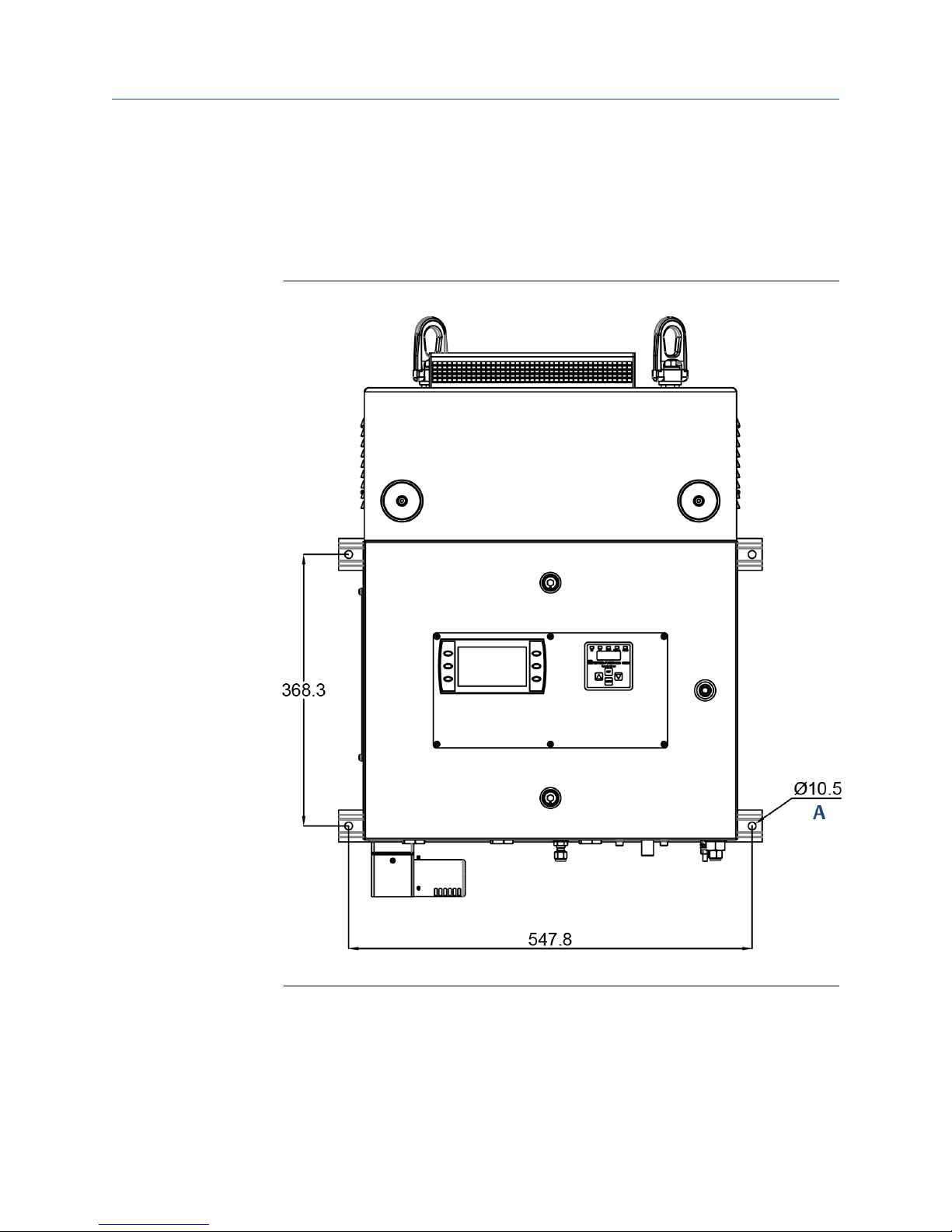
9.
The four wall fixing points must be 10.5 mm diameter mounting holes.
10. Make sure that the wall fixing points are capable of supporting a load of 110 kg (242
lb) each; this includes a x 2 factor of safety. Figure 1-5 shows the locations of the
mounting points on the analyzer. All mounting points are 10.5 mm diameter holes.
11. Make sure the bolts are secure. Do not over tighten the fasteners.
12. The analyzer must be mounted using the four off factory fitted and pre-drilled holes
on the brace bars. Refer to Figure 1-3.
13. The lifting eyes are to be removed and retained for future use. Threads must be
protected with a suitable grease and plastic grommets.
After mounting, no additional load is to be placed on the analyzer.
14. Do not place or leave loose items on flat surfaces.
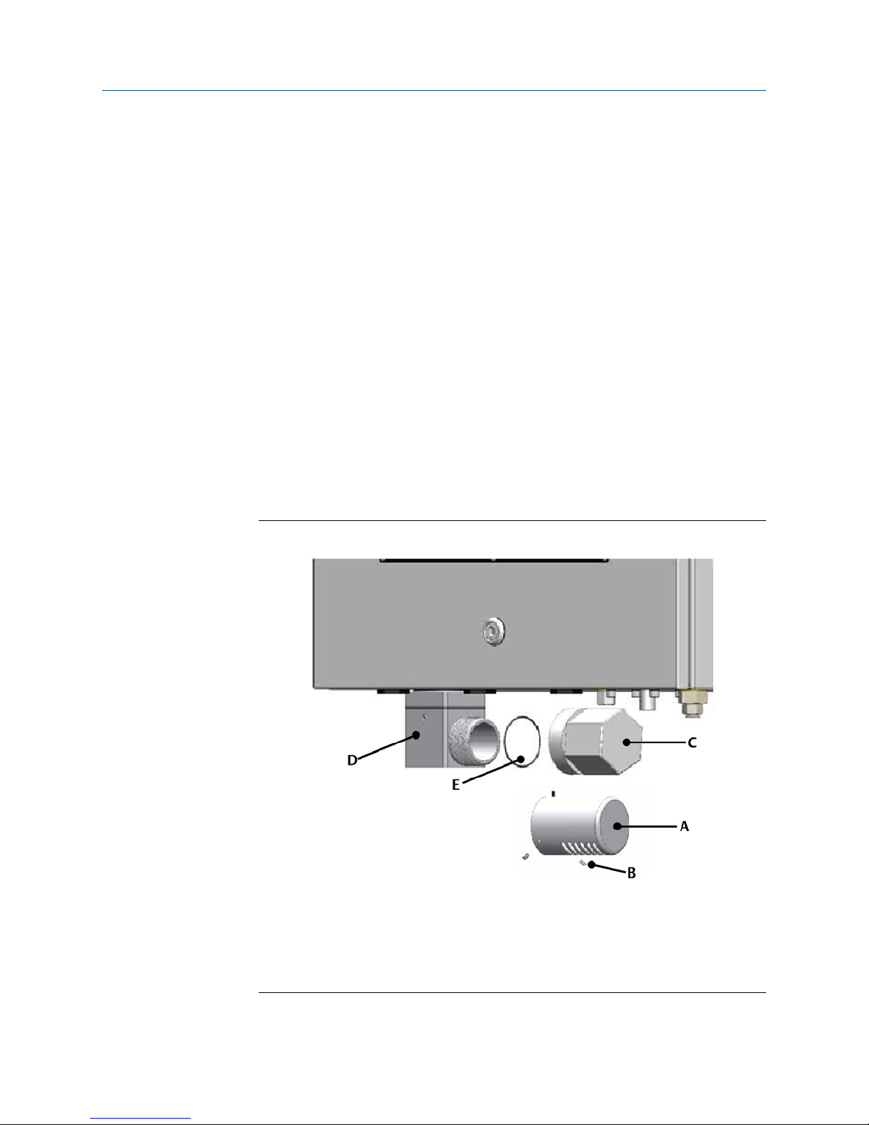
15. For transportation, the purge vent (D) located on the base of the analyzer is fitted
with a temporary protector cap (C). This protector cap MUST remain in place until
the analyzer is going to be commissioned. Refer to Figure 1-4.
The vent cap (A), O-ring (E) and grub screws (B) are shipped loose in the crate. Refer
to Figure 1-3.
Figure 1-4: Connecting the Purge Vent Cap
A. Vent cap
B.
3/32 in. socket grub screws
C. Protector cap
D. Purge vent
E. O-ring
20 Rosemount ™ CT5100 Ex
Quick Start Guide Introduction
D-7010-0055 August 2018
16. To complete the installation the protector cap MUST be removed from the purge
vent and the O-ring (E). The vent cap installed, locking in position with the grub
screws. Refer to Figure 1-3. An Allen key will be provided for the grub screws.
17.
The protector cap (C) must be retained as it will need to be refitted whenever the
analyzer is being shutdown for a prolonged period to seal the purge vent from fluid
ingress.
Figure 1-5: Mounting Details
A. Mounting Points
Quick Start Guide 21
Introduction Quick Start Guide
August 2018 D-7010-0055
Figure 1-6: Clearance with Door Open
1.5 Software version
The analyzer includes software that is used to control the operation of the analyzer. This
manual describes software version 5.7.13.
22 Rosemount ™ CT5100 Ex

Quick Start Guide Install
D-7010-0055 August 2018
2 Install
2.1 System overview
A complete Rosemount™ CT5100(Ex) system consists of a gas handling system, the
analyzer, and the associated interconnecting wiring and gas piping.
Measurement data from the analyzer can be displayed in the process control center. You
must provide the gas handling system and interconnecting wiring and gas piping.
The Rosemount CT5100(Ex) is supplied by Emerson. The gas handling system may be
provided by either you or Emerson, depending upon the specific installation. The circuit
breakers used to control the application of electrical power to the analyzer, the
interconnecting wires, and gas piping are provided by you.
In Figure 2-1, the items supplied by Emerson are colored blue; the items supplied by you
are colored purple. The green gas handling system may be provided by Emerson or you.
Table 2-1 lists the main items of the system.
Figure 2-1: Complete Rosemount CT5100(Ex) Installation
The analyzer contains an optical system with multiple lasers and a series of optical
components that provide an optical path, a heated multi-pass analysis cell, and sample
and outlet ports that can be connected to a gas handling system, and control and analysis
electronics. The number of lasers installed depends upon customer requirements. The
complete system operates from 110/230 Vac 50/60 Hz supply.
Gas concentrations are measured using mid-infrared optical absorption spectroscopy. The
light sources are , which are operated to produce wavelength sweeps that cover the
Quick Start Guide 23

Install Quick Start Guide
August 2018 D-7010-0055
absorption lines of the gases. The light from each laser is routed through an optical path to
the analysis cell, which provides measurement of low concentrations of the subject gases.
An external sample handling system conditions the sample gas and draws it through the
analysis cell. The light exits the multi-pass analysis cell and is directed to a receiver in the
analyzer. The variation in the intensity of light in the vicinity of the absorption lines is
measured, and the concentration is determined using a comprehensive spectral fitting
routine.
There is no sample conditioning provided within the analyzer; the sampled gas must be
brought within the parameters shown in the Installation, Operations, and Maintenance
Manual, Detailed system specifications in the before entering the analyzer. Detailed
characteristics of the analyzer are also given in the Installation, Operations, and
Maintenance Manual, Detailed system specifications.
Table 2-1: Main Items of the Rosemount CT5100(Ex) Installation
Item Name or
description
1 Rosemount
CT5100(Ex)
2 Rosemount
CT5100(Ex)
software package,
version 5.7.13
3 Gas handling
system
4 Heated gas sample
line hose
5 Exhaust line hose
(for sample gas)
6 Reference gas
cylinders
(instrument gas)
for calibration
purposes
7 Pressure regulator Customer Customer choice 1 per gas cylinder Required for
8 Pneumatic T-piece Customer Customer choice 1 Required for
Supplied by Part number Quantity Notes
Emerson Rosemount
CT5100(Ex)
Emerson N/A.Software is
embedded in the
system.
Customer
(optionally by
Emerson)
Customer Customer choice 1
Customer Customer choice 1
Customer Customer choice Dependent upon
Customer Choice
or Emerson
1
1 Version described
in manual
1
number of gases
being measured
calibration
calibration
9 Excess flow line Customer Customer choice 1 Required for
10 Power cables to
Rosemount
CT5100(Ex)
11 Cables from
Rosemount
CT5100(Ex) to
control center
24 Rosemount ™ CT5100 Ex
calibration
Customer Customer choice 1
Customer Customer choice 1

Quick Start Guide Install
D-7010-0055 August 2018
Table 2-1: Main Items of the Rosemount CT5100(Ex) Installation (continued)
Item Name or
description
13 Secondary circuit
breaker
Supplied by Part number Quantity Notes
Customer Customer choice
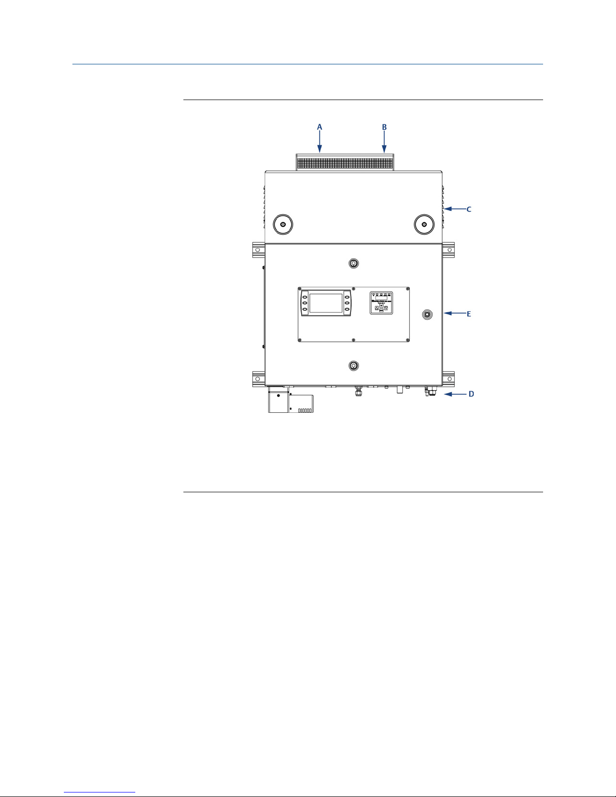
2.2 Gas inputs and outputs
About this task
The analyzer has two gas inputs and one gas output. See Figure 2-2.
Procedure
1.
The gas sample that is to be measured for impurities enters the analyzer through
the sample gas input port located on top of the analyzer (see Figure 2-2, Items A
and B).
2. Once the gas sample has been examined for impurities, it is expelled from the
analyzer through the sample gas return port (A).
Quick Start Guide 25
Install Quick Start Guide
August 2018 D-7010-0055
Figure 2-2: Gas Inlet and Outlet Connectors
A. Sample gas return port
B.
Sample gas input port
C. Top cover of Rosemount CT5100(Ex) (cell compartment)
D. Purge air supply
E. Laser/electrical compartment
3. The sample supply line must be heated all the way to the sample gas input port on
the analyzer to prevent condensation forming at any point in the sample supply
line.
2.3 Connecting the electrical/electronic inputs and
outputs
2.3.1 AC power
Power is connected to the analyzer instrumentation through the power entry point (B) and
the purge controller through the purge power and alarm entry point (A) fitted to the base
of the analyzer. Refer to Figure 2-3.
26 Rosemount ™ CT5100 Ex
 Loading...