

Page 1
Operations Manual
D-7010-0046, Rev A
Rosemount CT5100 Continuous Gas Analyzer
May 2016
Page 2

Preface
Published by Emerson.
All possible care has been taken in the preparation of this publication, but Emerson and its agents and distributors accept no liability
for any inaccuracies that may be found. This manual reflects the state of the product at the issue date below, but further
enhancements while in service may mean that the manual does not reflect your particular system.
Emerson reserves the right to make changes without notice both to this publication and the products which it describes.
Document Number: D-7010-0046
Rev A, May 2016
©
Emerson 2016. All rights reserved.
No part of this publication may be reproduced, stored in a retrieval system, or transmitted in any form or by any means electronic,
mechanical, photocopying, recording, or otherwise without the express prior written permission of the copyright holder.
If you require additional technical assistance, request help from Cascade Technical Support (cascade.support@emerson.com) or
Emerson distribution partners.
General inquiries about this or other Cascade Technologies products should be sent to cascade.info@emerson.com.
All trademarks used within this document are the property of their respective owners.
Page 3

Preliminary Information
Regulations and Standards
Regulations / Standards Description
2014/35/EU The Low Voltage Directive
2014/30/EU The Electromagnetic Compatibility Directive
2012/19/EU Waste Electrical and Electronic Equipment (WEEE) Directive
USA 21 CFR 1040.1 Laser products
NEC 505 National Electrical Code (issued by ANSI: American National Standards
Institute and NFPA 70: National Fire Protection Association)
EN 6223: 2008 EMC Safety Standard
BS EN 60825-1:2007 Safety of laser products. Equipment classification and requirements
(identical to IEC 608250-1 2007)
BS EN 61010-1 2010 IEC 61010-1 2010 Safety requirements for electrical equipment for measurements, control,
and laboratory use. General requirements
BS EN 61326-1: 2013 Electrical equipment for measurement, control, and laboratory use. EMC
requirements. General requirements
Associated publications
Maintenance Manual (D-7010-0009)
Quick Start Guide (D-7010-0052)
Compliance approvals
This product complies with USA 21 CFR 1040 .10. It is also designed and manufactured under an approved
quality management system to ISO 9001:2008.
CE marking
Emerson and the CT5100 Continuous Gas Analyzer have satisfied the requirements for applying the CE
marking to the CT5100 Continuous Gas Analyzer.
This equipment meets all requirements of the EMC and Low Voltage directives.
Waste disposal
Do not dispose of measuring tools into household waste!
Only for EC countries
In accordance with European Directive 2012/19/EU for Waste Electrical and Electronic Equipment and its
implementation into national right, measuring tools that are no longer usable must be collected separately
and disposed of in an environmentally correct manner.
Page 4

Safety and information notices
The following notices are used throughout this publication:
DANGER!
MAY CAUSE DEATH
Failure to follow this warning will result in death or serious injury to personnel.
WARNING!
DANGER TO PERSONNEL
Failure to follow this warning may result in injury to personnel.
CAUTION!
MAY CAUSE INJURY TO PERSONNEL OR DAMAGE TO EQUIPMENT
Failure to follow this warning may result in injury to personnel or cause damage to the equipment.
NOTICE
Important or tip messages will appear in this format.
Page 5

Safety Precautions
Operators, maintenance personnel, and authorized users must observe the following safety precautions and warnings.
DANGER!
ELECTRIC SHOCK
The CT5100 Continuous Gas Analyzer (CT5100 CGA) operates using mains voltage, which may cause death or serious injury to
personnel. Make sure that the circuit breakers are set to Off and locked out and tagged out off before removing the top cover or
opening the front cover.
Death, personal injury, and/or damage to persons and/or property may result if this is not observed.
WARNING!
FIRE, BURN, AND OPTICAL RADIATION EXPOSURE HAZARD
Operators and service personnel do not have access to the laser/electrical and the upper cell compartments for maintenance or
service.
Electrical shock or thermal burns may occur.
WARNING!
FLAMMABLE SUBSTANCES
Some parts of the CT5100 CGA may reach temperatures of 190 °C (374 °F) and may present an ignition source. Exercise care when
using oil, paint, cleaning rags, or other flammable substances near the CT5100 CGA. A fire may result if this precaution is not
observed. The interior of a CT5100 CGA is always hot unless it has been switched off and allowed to cool down.
WARNING!
EXPLOSION HAZARD
Always lock out the gas handling system when shutting down the CT5100 CGA. Unauthorized performance on the CT5100 CGA or its
associated pipes/hoses may result in highly flammable gas being released, causing fire or explosion. Failure to lock out gas handling
system may cause death.
WARNING!
EXPLOSION HAZARD
The sample gas in the system must be vented to prevent fire or explosion during maintenance and to prevent damage to the CT5100
CGA during startup.
The sample gas in the pipes leading to the CT5100 CGA must be purged to prevent hazards to personnel during maintenance. You
must purge the sample gas in accordance with the safe working procedures for this site.
Allow the CT5100 CGA and the system for returning the sample gas to run for five minutes to allow any sample gas in the instrument
to be returned to the exhaust.
Failure to vent sample gas may cause death.
Page 6
WARNING!
BURNS
Some parts of the CT5100 CGA may be heated to 190 °C (374 °F). To prevent burns, do not touch any of the hot parts. All parts of a
CT5100 CGA are always hot unless it has been switched off and allowed to cool down.
Before fitting, removing, or performing any maintenance on the CT5100 CGA, make sure that it has been switched off and allowed to
cool for at least two hours. Before performing any maintenance on, or in the vicinity of, the analysis cell, allow the CT5100 CGA to
cool for at least twelve hours as the analysis cell is insulated against heat loss.
When handling the CT5100 CGA, always use suitable protective gloves.
Personal injury and/or damage to property may result if these precautions are not observed. These precautions are particularly
important when working at heights. If a burn is received, seek medical treatment immediately.
WARNING!
OPTICAL RADIATION EXPOSURE HAZARD
The CT5100 CGA contains lasers. Opening the CT5100 CGA and attempting to perform adjustments and procedures other than those
specified in this manual may result in hazardous optical radiation exposure.
All lasers used within the CT5100 CGA are Class 1. The combined laser powers are sufficiently low at the first accessible aperture that
the unprotected eye will not be damaged. This class is eye safe under all operating conditions.
Failure to follow the correct procedures may cause damage to the eye. Do not look at the lasers with any kind of magnifier or optical
measuring device.
There are three types of laser that may be included in the CT5100 CGA: Quantum Cascade Lasers (QCLs), Interband Cascade Lasers
(ICLs), and diode lasers. The lasers within the CT5100 CGA are Class 1. The characteristics of the lasers contained within the CT5100
CGA are given in the table below.
Parameter QCL ICL Diode Comment
Operation mode Pulsed Pulsed Pulsed
Lasers per system 1 - 6 1-6 1-6 Maximum of 6 lasers per system
Wavelength 4 - 10 µm 2- 5 µm Approximately 760 nm
Power < 5 mW < 5 mW < 5 mW Combined power of QCL at first accessible
aperture: < 9.62mW
Pulse duration < 1 µs < 1 µs < 5 µs
Pulse repetition
< 100 kHz < 100 kHz < 100 kHz
frequency
Duty cycle < 5% < 5% < 25%
The combined power of the QCL, ICL, and diode lasers at the first accessible aperture is < 9.62 mW.
The CT5100 Continuous Gas Analyzer has warning labels in appropriate positions according to USA 21 CFR 1040.10. The location of
laser safety labels on the CT5100 Continuous Gas Analyzer is specified in Section 4.3.
The use of controls or adjustments or performance of procedures other than those specified herein may result in hazardous radiation
exposure.
Page 7

WARNING!
HAZARDOUS SUBSTANCES
The CT5100 CGA may contain hazardous substances. Always handle CT5100 CGA assemblies and components with extreme caution.
Wear personal protective equipment (PPE) when handling the equipment.
Gas handling components within the CT5100 CGA contain particulate matter residue from the sample gases. Over the life of the
CT5100 CGA, the concentration of particulate matter will become enriched within the gas handling components. When performing
repairs and maintenance on the CT5100 CGA:
• Handle used gas handling components with extreme caution.
• Avoid direct skin contact with used gas handling components.
• Do not smoke, drink, or eat in the work area.
• Wear goggles or eye shields.
• Wear a suitable face mask to protect against inhalation of particulate matter.
• Keep food and beverages away from the CT5100 Continuous Gas Analyzer.
• Do not wet fingers, eyes, or any exposed skin.
• Pack used gas handling components for disposal in sealed packaging and label them Contaminated.
• Dispose of contaminated items as hazardous material in accordance with applicable local, national, or international health
and safety regulations and pollution regulations.
WARNING!
TRANSPORTATION HAZARD
Handle the CT5100 CGA with caution during unpacking, installation, maintenance, and transport to prevent crushing of hands, feet,
or other body parts.
The CT5100 CGA weighs 50.3 kg (111 lb.) and should always be lifted and moved using suitable lifting/moving equipment. Wear
suitable protective gloves and protective footwear. When preparing the CT5100 CGA for transport by air, road, or rail, safeguard the
CT5100 CGA against movement or break-away during transport by securely strapping it in place.
WARNING!
HAZARDOUS GAS
The product stream that the CT5100 CGA is examining may be hazardous even at low concentrations. Special care should therefore
be taken to ensure that the sample gas return port either returns the sample gas to the product stream or discharges the sample gas
to a location that will not cause a hazard.
WARNING!
HIGH PRESSURE GAS AND AIR
The calibration gas supply and compressed air supply operate at a pressure that can cause injury, e.g., damage to eyes and skin
punctures from debris blown by the high pressure gas or compressed air. Always lock off or tag out the calibration gas supply and
compressed air supply when shutting down the CT5100 CGA.
CAUTION!
EQUIPMENT DAMAGE
Do not power up or try to operate the CT5100 CGA unless it is physically secure and all electrical and pneumatic connections to the
CT5100 CGA are in place.
Before commencing the startup process, it is important to ensure that electrical power, sample gas handling facilities, and any
calibration gases that are required are available to the CT5100 CGA.
Failure to perform pre-system startup checks may cause damage to equipment.
Page 8

CAUTION!
EQUIPMENT DAMAGE
Always follow the startup procedure. Damage to the CT5100 CGA may result from a failure to follow this procedure.
CAUTION!
EQUIPMENT DAMAGE
Always follow the shutdown procedure. Damage to the CT5100 CGA may result from a failure to follow this procedure.
CAUTION!
LASER RADIATION
Invisible laser radiation. Do not stare into beam. Class 1 laser.
Failure to follow the correct procedures may cause damage to the eye.
CAUTION!
EMC
This is a Class A product. In a domestic environment, this product may cause radio interference, in which case the user may be
required to take adequate measures.
Page 9

Abbreviations
The following abbreviations are used in this manual.
©
Copyright
% Percent
< Less than
° Degree
AC Alternating current
Barg Pressure, in units of bars, above or below atmospheric pressure
BS British Standard
C Celsius
CE European Conformity
CFR Code of Federal Regulations
CGA Continuous Gas Analyzer
CH
4
Methane
CO Carbon monoxide
CO
2
Carbon dioxide
DC Direct current
Deg Degree (temperature)
e.g. For example
EC European Community
EMC Electromagnetic compatibility
EU European Union
Hrs Hours
Hz Hertz
H2O Water
ICL Interband Cascade Laser
IEC International Electro-technical Commission
in. Inches
IPxx Ingress protection (the xx are numbers that define the level of protection)
ISO International Organisation for Standardisation
K Thousand
kg Kilogram
kHz Kilo hertz
L Liter
lb. Pound
LCD Liquid crystal display
LED Light emitting diode
Page 10

L/min Liters per minute
m Meter
3
m
Cubic meter
mA Milliamp
Max Maximum
mBar milli-Bar
mbps Megabits per second
mg Milligram
3
mg/m
Microgram/cubic meter
Mid IR Mid Infrared
min Minute
mm Millimeter
O
2
N
2
Oxygen
Nitrogen
NEC National Electrical Code
NFPA National Fire Protection Association
nm Newton meter
NO Nitric oxide
NO
2
Nitrogen dioxide
N2O Nitrous oxide
NH
3
Ammonia
No. Number
O
2
Oxygen
PC Personal computer
PM Preventative maintenance
ppm Parts per million
psi Pounds per square inch
QCL Quantum Cascade Laser
Torr Unit of pressure defined as exactly 1/760 of a standard atmosphere
UKAS United Kingdom Accreditation Service
USA United States of America
USB Universal serial bus
V Volt
VA Volt-ampere
Vac Volt alternating current
W Watt
WEEE Waste electrical and electronic equipment
μm Micro-meter
Page 11

Contents
Contents
Chapter 1 Introduction ...................................................................................................................1
1.1 Description .................................................................................................................................. 1
1.2 Customer information ................................................................................................................. 1
1.3 Safety precautions ....................................................................................................................... 2
1.4 Qualified personnel ......................................................................................................................2
1.5 Software version .......................................................................................................................... 2
Chapter 2 Theory of Operation ....................................................................................................... 3
2.1 Overview ......................................................................................................................................3
2.2 Quantum Cascade Laser ..............................................................................................................3
2.3 Measurement process ..................................................................................................................3
Chapter 3 Description .................................................................................................................... 5
3.1 Equipment purpose and role ........................................................................................................5
3.2 System overview ..........................................................................................................................6
3.3 Gas inputs and outputs ................................................................................................................ 8
3.4 Electrical/electronic inputs and outputs .....................................................................................10
3.5 Controls and indicators ..............................................................................................................12
3.6 Optical description .....................................................................................................................12
Chapter 4 Specifications ...............................................................................................................15
4.1 Gas detection .............................................................................................................................15
4.2 Detailed system specifications ...................................................................................................15
4.3 Safety and system labels and annotation ................................................................................... 18
Chapter 5 Controls and display controller .....................................................................................23
5.1 Introduction ...............................................................................................................................23
5.2 Operating states ........................................................................................................................ 23
5.3 Startup procedure ......................................................................................................................23
5.4 Shutdown procedure ................................................................................................................. 24
5.5 Front panel controls and indicators ............................................................................................24
5.6 Display controller .......................................................................................................................26
5.7 Gas sensor main screen ..............................................................................................................27
5.8 Pressure and Temperature screen ................................................................................................ 29
5.9 Help system ...............................................................................................................................29
5.10 Calibration ................................................................................................................................. 30
5.11 BACK button ...............................................................................................................................30
Chapter 6 Startup procedure ........................................................................................................33
6.1 Introduction ...............................................................................................................................33
6.2 Preparation for use .....................................................................................................................33
6.3 Startup .......................................................................................................................................34
Chapter 7 Operation .....................................................................................................................37
7.1 Introduction ...............................................................................................................................37
7.2 Normal operation ...................................................................................................................... 37
Chapter 8 Shutdown procedure ................................................................................................... 39
8.1 Introduction ...............................................................................................................................39
8.2 Shutdown procedure ................................................................................................................. 40
Operations Manual i
Page 12

Contents
Chapter 9 Gas Calibration Procedures ...........................................................................................45
9.1 Required tools ............................................................................................................................45
9.2 Main menu .................................................................................................................................45
9.3 Zero Calibration ......................................................................................................................... 47
9.4 Span gas calibration ................................................................................................................... 52
Chapter 10 Preventative Maintenance ........................................................................................... 59
10.1 Maintenance ..............................................................................................................................59
10.2 Schedule ....................................................................................................................................59
ii Rosemount CT5100
Page 13

1 Introduction
Topics covered in this chapter:
• Description
• Customer information
• Safety precautions
• Qualified personnel
• Software version
1.1 Description
The CT5100 Continuous Gas Analyzer, referred to hereafter as CT5100 CGA, is an
electronic sensor that uses laser spectroscopy to perform analysis of process gas streams.
The function of the CT5100 CGA is to detect and measure up to ten different types of gas
at concentrations ranging from parts per million (ppm) to percentage levels in the process
gas stream.
Introduction
This Operations Manual is intended for the personnel who operate and maintain the
equipment.
1.2 Customer information
This manual contains all the important information that must be followed to ensure the
correct operation and safety of personnel when operating the CT5100 CGA.
Operators and maintenance personnel must read this manual carefully before
commencing any work on the CT5100 CGA.
The manual is divided into chapters, which will allow you to easily find the information
required.
For information regarding maintenance, installation, and spare parts, contact your local
service representative.
Emerson is committed to continuously improving its products and documentation. Every
effort will be made to include in the documentation any modifications by the
manufacturer. However, it should be noted that this document reflects the supplied
sensor at the revision date on the front cover.
Should you require further information, or should particular problems arise that are not
covered in this Manual, then additional help can be requested from Cascade Technical
Support (cascade.support@emerson.com) or Cascade Technologies Ltd distribution
partners. Further contact details for Cascade technologies Ltd can be found in the
preliminary material of this manual.
Operations Manual 1
Page 14

Introduction
1.3 Safety precautions
WARNING!
Before installing or performing any maintenance on the CT5100 CGA, read and understand the
safety information given in the preliminary material of this manual.
The CT5100 CGA described in this manual has been quality control tested and left the
manufacturer in pristine condition. To achieve the correct and safe operation of this
product, it must be transported, installed, operated, and maintained as described by the
manufacturer.
All lasers used within the instrument are Class 1. The emitted laser light is invisible (midinfrared) and the pulse duration so short that the unprotected eye will not be damaged.
The nature of the laser beam path and beam width further ensures that it should be
impossible to cause any eye damage. The instrument has warning labels at appropriate
positions in accordance with USA 21 CFR 1040.10.
1.4 Qualified personnel
This manual provides operation and maintenance personnel with the level of knowledge
required to safely start, operate, and switch off the CT5100 CGA.
The installation, advanced operation, switching off, and servicing of the CT5100 CGA must
only be performed by technically qualified personnel in the field of instrumentation and
control who are familiar with this manual and have been specially trained on the CT5100
CGA. Only qualified and trained persons have the required specific knowledge to correctly
interpret the general safety information, warnings, and procedures given in this manual
and apply them to this particular application. Emerson or its distribution partners can
provide this training on request.
Knowledge of the safety information within this manual and its technically correct
implementation are prerequisites for danger-free operation, installation, and maintenance
of the CT5100 CGA.
1.5 Software version
The CT5100 CGA includes software that is used to control the operation of the instrument.
This manual describes software version 4.4.1-1.
2 Rosemount CT5100
Page 15

2 Theory of Operation
Topics covered in this chapter:
• Overview
• Quantum Cascade Laser
• Measurement process
2.1 Overview
The CT5100 CGA is a gas sensor system that can be configured to measure the
concentrations of multiple small molecules carried in the gas sample. The types of
molecules that are measured depend on the system configuration.
The CT5100 CGA can be configured to detect and measure up to ten gases, with ranges
varying from parts per million (ppm) to percent (%) levels. A detailed description of the
system is given in Chapter 3 of this manual.
Theory of Operation
2.2 Quantum Cascade Laser
The CT5100 CGA uses up to six Quantum Cascade Lasers to detect and measure the gases.
Each QCL measures between one and three gases.
Inside the QCL, which is about the size of a pin head, electrons cascade down a series of
quantum wells, producing a photon at each step. This cascade of electrons can produce
between 20 and 100 photons per electron, giving QCLs higher output power than
traditional semi-conductor lasers.
The lasing wavelength of a QCL is determined by adjusting the physical thickness of the
semiconductor layers, giving access to high power lasers covering the mid-infrared
spectral region. A QCL has no need for cryogenic cooling, has excellent spectral quality in
chirped mode, and good tunability.
2.3 Measurement process
In the CT5100 CGA, gas concentrations are measured using mid-infrared optical
absorption spectroscopy. The light sources are QCLs, which are operated to produce
wavelength sweeps that cover the absorption lines of the gases to be measured.
Sample gas, which may contain impurity gases that are to be detected and measured, is
conditioned and drawn into the CT5100 CGA. Inside the CT5100 CGA, the sample gas is
fed into an analysis cell, where the beams from the QCLs are passed through the gas. The
analysis cell contains a set of mirrors that bounce the light back and forth many times,
Operations Manual 3
Page 16

Theory of Operation
which lengthens the path of the lasers through the gas. On exiting the analysis cell, the
light is detected by a receiver unit. The variation in the intensity of light in the vicinity of
absorption lines for the gases being detected is measured, and the concentration is
determined using a comprehensive spectral fitting routine.
4 Rosemount CT5100
Page 17

3 Description
Topics covered in this chapter:
• Equipment purpose and role
• System overview
• Gas inputs and outputs
• Electrical/electronic inputs and outputs
• Controls and indicators
• Optical description
3.1 Equipment purpose and role
The CT5100 CGA shown in Figure 3-1 is a gas sensor system that can be configured to
measure the concentrations of multiple small molecules contained in a gas sample that is
provided to the CT5100 CGA via a sample line. The types of molecules that are measured
depend on the system configuration.
Description
Operations Manual 5
Page 18

Description
CT5100 Continuous Gas AnalyzerFigure 3-1:
The CT5100 CGA can be configured to detect and measure up to ten different gases,
depending on the combination of laser modules fitted.
3.2 System overview
A complete CT5100 CGA, as shown in Figure 3-2, consists of a gas handling system, the
CT5100 CGA, and the associated interconnecting wiring and gas piping. Measurement
data from the CT5100 CGA can be displayed in the process control center.
The CT5100 CGA is supplied by Emerson. The gas handling system may be provided by
either you or Emerson, depending upon the specific installation. The circuit breakers used
to control the application of electrical power to the CT5100 CGA, the interconnecting
wires, and gas piping are provided by you. In Figure 3-2, the items supplied by us are
colored blue; the items supplied by you are colored purple. The green Gas Handling
System may be provided by you or us. Table 3-1 lists the main items of the system.
6 Rosemount CT5100
Page 19

Description
CT5100 CGA installationFigure 3-2:
The CT5100 CGA contains an optical system with multiple lasers and a series of optical
components that provide an optical path, a heated multi-pass analysis cell, sample and
outlet ports that can be connected to a gas handling system, and control and analysis
electronics. The number of lasers installed depends upon customer requirements. The
complete system operates from either 100 or 240 Vac 50/60 Hz supply. You must specify
whether you want 100 or 240 Vac on your order.
Gas concentrations are measured using mid-infrared optical absorption spectroscopy. The
light sources are QCLs, which are operated to produce wavelength sweeps that cover the
absorption lines of the gases. The light from each laser is routed through an optical path to
the analysis cell, which provides measurement of low concentrations of the subject gases.
The sample gas is conditioned and drawn through the analysis cell by an external sample
handling system. The light exits the multi-pass analysis cell and is directed to a receiver in
the CT5100 CGA. The variation in the intensity of light in the vicinity of the absorption lines
is measured, and the concentration is determined using a comprehensive spectral fitting
routine.
There is no sample conditioning provided within the CT5100 CGA; the sampled gas must
be brought within the parameters shown in Table 4-3 before entering the CT5100 CGA.
Detailed characteristics of the CT5100 CGA are also given in Section 4.2.
Main items of the CT5100 CGA installationTable 3-1:
Item Name or description Supplied by Part number Quantity Notes
1 CT5100 CGA Emerson CT5100 1
2 CT5100 CGA software
package, version 4.0
Emerson N/A.
Software is
embedded in the
system.
1 Version
described
in manual
Operations Manual 7
Page 20

Description
Main items of the CT5100 CGA installation (continued)Table 3-1:
Item Name or description Supplied by Part number Quantity Notes
3 Gas handling system Customer
(optionally by
Emerson)
4 Heated gas sample line
hose
5 Exhaust line hose (for
sample gas)
6 Reference gas cylinders
(instrument gas) for
calibration purposes
7 Pressure regulator Customer Customer choice 1 per gas
8 Pneumatic T-piece Customer Customer choice 1 Required
9 Excess flow line Customer Customer choice 1 Required
10 Power cables to
CT5100 CGA
11 Cables from CT5100
Continuous Gas
Analyzer to control
center
12 Main circuit breaker Customer Customer choice
Customer Customer choice 1
Customer Customer choice 1
Customer Customer choice Dependent
Customer Customer choice 1
Customer Customer choice 1
Customer choice
or Emerson
1
upon
number of
gases being
measured
cylinder
Required
for
calibration
for
calibration
for
calibration
3.3 Gas inputs and outputs
The CT5100 CGA has one gas input and one gas output (Figure 3-3).
1. The gas sample that is to be measured for impurities enters the instrument through
the sample gas input port (A) located on top of the CT5100 CGA.
2. Once the gas sample has been examined for impurities, it is expelled from the
instrument through the sample gas return port (B).
8 Rosemount CT5100
Page 21

Description
Gas inlet and outlet connectorsFigure 3-3:
A. Sample gas input port
B. Sample gas return port
C. Top cover of CT5100 CGA (cell compartment)
D. Laser/electrical compartment
3. The sample supply line must be heated all the way to the sample gas input port on
the CT5100 CGA to prevent condensation forming at any point in the sample supply
line.
DANGER!
HAZARDOUS GASES
The product stream that the CT5100 CGA is examining may be hazardous even at low
concentrations. Special care should be taken to ensure that the sample gas return port
either returns the sample gas to the product stream or discharges the sample gas to a
location that will not cause a hazard. Hazardous gases may cause death.
Operations Manual 9
Page 22

Description
3.4 Electrical/electronic inputs and outputs
Electrical / electronic connectorsFigure 3-4:
A. Analog/digital conduit
B. Analog/digital conduit
C. Power conduit
Electrical/electronic connections to the CT5100 CGA are made through three electrical
conduits located on the underside of the instrument, as shown in Figure 3-4. Use the wiring
diagram to make the electrical user connections as shown below.
10 Rosemount CT5100
Page 23
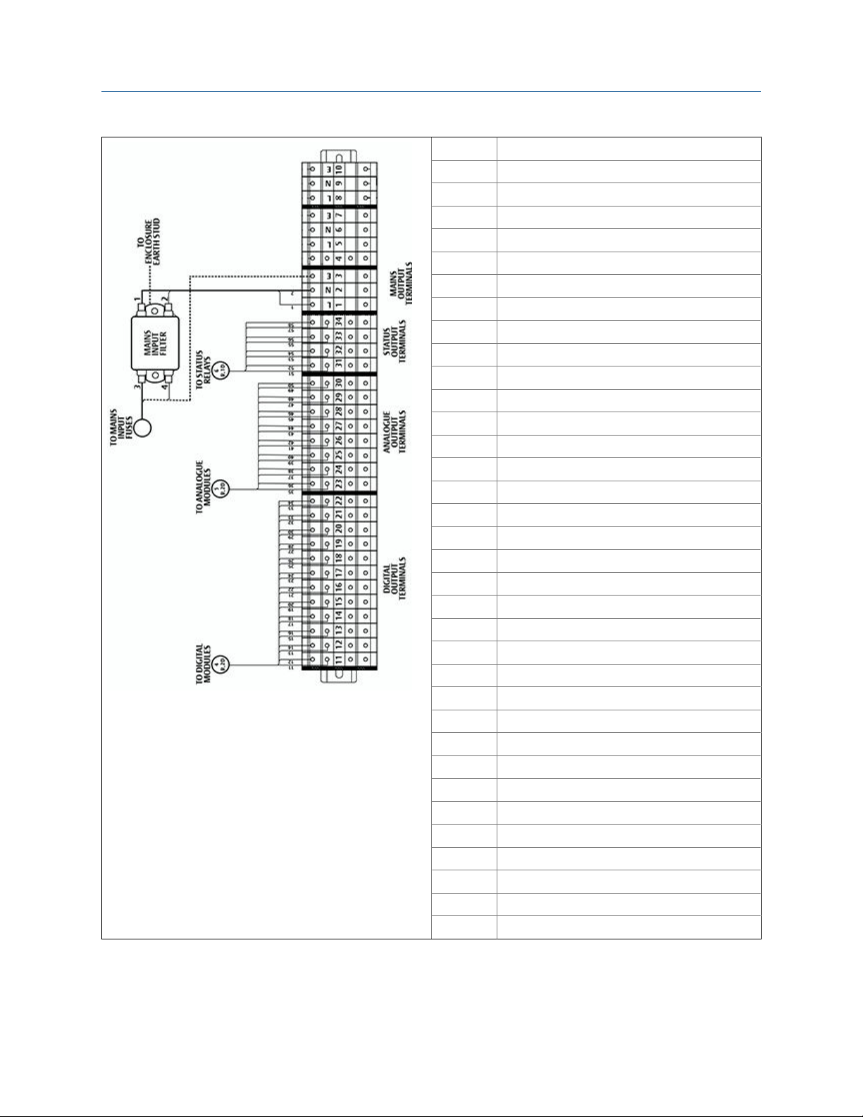
Note: Maximum number of user terminals shown. These
may be reduced dependant on number and type of
Analog/Digital outputs required.
Description
Terminal Function
1 SENSOR SYSTEM SUPPLY (L)
2 SENSOR SYSTEM SUPPLY (N)
3 EARTH
4 PURGE ALARM CONTACTS (Not used)
5 PURGE SYSTEM SUPPLY (L) (Not used)
6 PURGE SYSTEM SUPPLY (N) (Not used)
7 EARTH
8 PURGE SOLENOID (L) (Not used)
9 PURGE SOLENOID (N) (Not used)
10 EARTH
11 DIGITAL OUTPUT 1
12 DIGITAL OUTPUT 2
13 DIGITAL OUTPUT 3
14 DIGITAL OUTPUT 4
15 DIGITAL OUTPUT 5
16 DIGITAL OUTPUT 6
17 DIGITAL OUTPUT 7
18 DIGITAL OUTPUT 8
19 DIGITAL OUTPUT 9
20 DIGITAL OUTPUT 10
21 DIGITAL OUTPUT 11
22 DIGITAL OUTPUT 12
23 ANALOG OUTPUT 1
24 ANALOG OUTPUT 2
25 ANALOG OUTPUT 3
26 ANALOG OUTPUT 4
27 ANALOG OUTPUT 5
28 ANALOG OUTPUT 6
29 ANALOG OUTPUT 7
30 ANALOG OUTPUT 8
31 STATUS OUTPUT 1 (Check function)
32 STATUS OUTPUT 2 (Maintenance Required)
33 STATUS OUTPUT 3 (Out of Specification)
34 STATUS OUTPUT 4 (Failed)
Electrical power is applied to the instrument through the power conduit (C).
Operations Manual 11
Page 24

Description
The power supply is 110 to 240 Vac, 50/60 Hz ± 10%. AC to DC power converters inside the
instrument automatically adjust in response to the input voltage level and ensure that the
correct DC voltage is available inside the instrument. The instrument is electrically
protected by an internal 5 A, 250 VA fast acting fuse on the instrumentation electrical
supply line and an internal 2 A, 250 VA fuse on the purge electrical supply line.
CAUTION!
You must ensure that the mains supply cable used is of a suitable rating for the unit power
requirements. Failure to do so may result in personal injury and/or damage to persons and/or
property.
The digital outputs conduit (B) provides an Ethernet output from the instrument that may
be used for downloading data for failure diagnosis purposes or for downloading data to the
process control center.
The results of the gas analysis are output from the instrument through the 4-20 mA analog
or Modbus outputs and sent to your process control center.
The optional digital outputs provide fault indications to your process control center. Each
digital output is connected to a normally closed relay, located inside the CT5100 CGA,
which will open in response to the detection of a specific fault. The possible causes of a
fault indication are:
1. The sample gas concentration is outside of specification, i.e., the sample gas
concentration has exceeded the measurement range of the instrument.
2. The CT5100 CGA is out of specification or has developed a fault.
NOTICE
The installation of the gas analyzer shall be in accordance with National Electrical Code (NEC).
3.5 Controls and indicators
The controls and indicators on the CT5100 CGA are described in Section 5.5 of this manual.
3.6 Optical description
The laser modules are located in the core of the CT5100 CGA. Each laser module produces
a separate light beam, and these beams are combined linearly as the modules are aligned
in the system. The combined beams are closely coupled, parallel, and coaxial about a
virtual line. The laser light beams pass through a baseplate onto an optical steering
assembly, which directs the laser beam through the sample cell.
The sample cell contains a set of mirrors to create a path through the sample gas that is
between 2 m and 5 m through multiple reflections along the length of the cell. The laser
beams exit the cell at the opposite end from where they entered and are directed using a
second optical block to a receiver.
12 Rosemount CT5100
Page 25

Description
By measuring and analyzing the light detected by the receiver unit, it is possible to
accurately determine the concentrations of the target molecules within the gas sample
cell.
Operations Manual 13
Page 26

Description
14 Rosemount CT5100
Page 27

4 Specifications
Topics covered in this chapter:
• Gas detection
• Detailed system specifications
• Safety and system labels and annotation
4.1 Gas detection
The CT5100 CGA is highly configurable in the gases that can be detected and their range of
concentrations.
4.2 Detailed system specifications
Specifications
Table 4-1 gives the physical characteristics of the CT5100 CGA. Schematic diagrams of the
sensor and mounting points are shown in Figure 4-1and Figure 4-2. Table 4-2 gives the
general characteristics of the instrument.
Physical characteristicsTable 4-1:
CT5100 CGA Value Units Comment
Gas analyzer
dimensions
Gas analyzer weight 50.35
General characteristicsTable 4-2:
CT5100 CGA Value Units Comment
Instrumentation supply
voltage
Peak power consumption 500 W Max consumption per gas analyzer
Continuous steady-state
power consumption
Electrical compartment
enclosure
Optical compartment
enclosure
Measurement technique - - Mid IR absorption spectroscopy
Mid IR source - - Quantum Cascade Laser
575 x 286 x 641
22.64 x 11.25 x 25.24
111
110 or240 V AC 50/60 HZ ± 10%
300 W Once the gas analyzer has stabilized and the analysis cell
- -
- - Stainless steel
mm
in.
kg
lb.
has reached the temperature set point
Stainless steel
Length x Width x Height
Operations Manual 15
Page 28

Specifications
General characteristics (continued)Table 4-2:
CT5100 CGA Value Units Comment
Near IR source - - Interband Cascade Laser
Diode Laser
Laser classification Class 1 BS EN 60825-1: 2007 safety of laser products. Equipment
classification and requirements (identical to IEC 60825-1
2007)
Inlet gas port connector 6 mm or 1/4 in. Swagelok type, factory-configured, specify on order
Outlet (Exhaust) gas port
connector
Measurement result signals 4 to 20 mA 4 or 8 channel outputs, specify on order
6 mm or 1/4 in. Swagelok type, factory-configured, specify on order
10/100 Mbps Ethernet
16 Rosemount CT5100
Page 29

Specifications
CT5100 Continuous Gas Analyzer dimensions - front viewFigure 4-1:
Operations Manual 17
Page 30

Specifications
CT5100 Continuous Gas Analyzer dimensions - top viewFigure 4-2:
Table 4-3 gives the environmental characteristics of the CT5100 CGA.
Environmental characteristicsTable 4-3:
Environmental characteristic Value Units Comment
Operating temperature range 5 to 45
41 to 113
Sample gas temperature range 50 to 195
122 to 383
Sample gas moisture content 20 % Maximum
Sample gas particulate density 5 mg/m
Sample gas particulate size 10 μm
IP code 66 IP to IEC 60529
Sensor humidity range 10 to 95 % Relative humidity (non-
Operating altitude 0 to 2,000 m
°C
°F
°C
°F
Ambient temperature
Factory set, specify on order
3
condensing) at 45 °C (113 °F)
4.3 Safety and system labels and annotation
The labels and annotation applied to the CT5100 CGA are specified in Table 4-4.
18 Rosemount CT5100
Page 31

Safety and system labelsTable 4-4:
Label type Example Location
Identification label
(including serial
number and model
number
Front panel
Specifications
Fuse identification
label
Ratings label Enclosure side panel
Laser radiation
CAUTION label
1. Back plate
2. Top right inside of
door
Baseplate
Laser module
identification label
On each laser module
housing
Operations Manual 19
Page 32

Specifications
Safety and system labels (continued)Table 4-4:
Label type Example Location
Intrinsically safe label 1. HMI
2. Intrinsically safe
sensor barrier
Terminal label Top left inside of door
Earth identification
label
Back plate
20 Rosemount CT5100
Page 33

Specifications
Safety and system labels (continued)Table 4-4:
Label type Example Location
Manufacturer's label On analysis cell heater
block
Electrical safety label On inside of electrical
compartment door
AC Power Supply
Danger label
1. On outside of
electrical
compartment door
2. On manifold block
of air overpressure
system
Operations Manual 21
Page 34

Specifications
22 Rosemount CT5100
Page 35

5 Controls
Topics covered in this chapter:
• Introduction
• Operating states
• Startup procedure
• Shutdown procedure
• Front panel controls and indicators
• Display controller
• Gas sensor main screen
• Pressure and Temperature screen
• Help system
• Calibration
• BACK button
Controls
5.1 Introduction
This chapter describes the controls, displays, and indicators on the CT5100 CGA and how
to use the display controller located on the front panel of the instrument.
5.2 Operating states
The CT5100 CGA has two operating states: Work Mode and Off.
1. As the CT5100 CGA is designed for long term continuous operation, it is usually in
Work Mode.
2. The CT5100 CGA is normally only placed in the Off state for maintenance.
5.3 Startup procedure
The startup procedure described in Chapter 6 must be followed or damage to the CT5100
CGA may result. The description of normal operation provided in Chapter 7 of this manual
assumes that the startup procedure has been followed and completed correctly.
CAUTION!
EQUIPMENT DAMAGE
Always follow the startup procedure. Damage to the CT5100 CGA may result from a failure to
follow the startup procedure.
Operations Manual 23
Page 36

Controls
5.4 Shutdown procedure
To switch off the instrument, the shutdown procedure described in Chapter 8 must be
followed or damage to the CT5100 CGA may result.
CAUTION!
EQUIPMENT DAMAGE
Always follow the shutdown procedure. Damage to the CT5100 CGA may result from a failure
to follow the shutdown procedure.
5.5 Front panel controls and indicators
The CT5100 CGA is configured from the two control displays located on the front panel
(Figure 5-1).
24 Rosemount CT5100
Page 37

Controls
Front panelFigure 5-1:
A. Display controller
NOTICE
On/Off circuit breakers
There are no On/Off switches on the CT5100 CGA. The application of electrical power to the
instrument is controlled through an external circuit breaker.
The circuit breaker is a simple 2-pole on/off circuit breaker that must be set to On to permit the
safe operation of the CT5100 CGA.
Operation of the CT5100 CGA is controlled primarily through the display controller
(Figure 5-2).
Operations Manual 25
Page 38

Controls
Display controllerFigure 5-2:
5.6 Display controller
Display controller buttonsFigure 5-3:
A. LCD display
B. Configurable button
C. Scroll button
D. Configurable button
E. Configurable button
F. Scroll button
G. Configurable button
Operation of the CT5100 CGA is controlled through the six buttons on the display
controller: Figure 5-3.
The LCD display (A) can be used to display:
1. The gas concentration measurements obtained
26 Rosemount CT5100
Page 39

2. The operating temperature and pressure
3. Help screens
4. Step-by-step calibration and diagnostics
The two scroll buttons (C and F) are used to scroll through the information on the LCD
display. The right-hand scroll button (C) is used to scroll up, and the left-hand scroll button
(F) is used to scroll down.
The other four buttons (B, D, E, and G) are configured to perform different functions
according to which the software screen is shown on the LCD display.
5.7 Gas sensor main screen
When the CT5100 CGA is switched on, at the end of the startup procedure, the gas sensor
main screen (Figure 5-4) appears. The gas sensor main screen is the screen that is normally
displayed.
NOTICE
Controls
The gas concentrations shown in the following screenshots may be different from those shown
in your particular CT5100 CGA. They indicate the functionality of the software, which it the
same regardless of the gases or gas concentrations being measured.
Gas sensor main screenFigure 5-4:
The gas sensor main screen displays the gas concentration measurements obtained by the
CT5100 CGA. In the example shown in Figure 5-4, the gases nitric oxide (NO), nitrogen
dioxide (NO2), oxygen (O2), carbon monoxide (CO), and carbon dioxide (CO2) are being
measured, and for each gas the concentration detected is in parts per million (ppm) or
percentage as applicable.
At the end of the startup procedure, the gas measurements initially appear as 0.00 ppm
until the first readings are taken. After a few seconds, the initial gas concentrations are
displayed.
Operations Manual 27
Page 40

Controls
The gas sensor main screen also shows the status of the CT5100 CGA. In the example
shown in Figure 5-5, the instrument is Running and OK (i.e., no faults have been identified).
This area of the display shows any errors detected by the software.
On the software screens, highlighted items are links to other screens in the software. To
access a screen, press the button next to the highlighted item.
Gas sensor main screen buttonsFigure 5-5:
A. MENU button
B. MENU text
C. PAGE text
D. PAGE button
E. HELP button
F. HELP text
G. STATUS button
PAGE (C) is a link between the gas sensor main screen and the Pressure and Temperature
screen (described in Section 5.8). Press the PAGE button (D) to toggle between these two
screens.
HELP (F)is a link to the Help system. Press the HELP button to go to the HELP screen
(described in Section 5.9).
MENU (B) is a link to the main menu of the software. Press the MENU button (A) to go to the
MAIN MENU screen (described in Section 5.10).
On the gas sensor main screen, the STATUS button (G) has no function when the CT5100
CGA is operating correctly. If, however, the software detects a fault, an error message is
displayed. Press the STATUS button to get further information on the error.
28 Rosemount CT5100
Page 41

5.8 Pressure and Temperature screen
The Pressure and Temperature screen (Figure 5-6) shows pressure and temperature
measurements taken inside the CT5100 CGA.
Pressure and Temperature screenFigure 5-6:
Controls
The Cell reading is the temperature, in °C, of the analysis cell.
The Gas reading is the temperature, in °C, of the gas within the analysis cell.
The Pres reading is the pressure, measured in Torr, inside the analysis cell.
NOTICE
A Torr is a non-SI unit of pressure defined as 1/760 of standard atmospheric pressure and is
equal to the fluid pressure of 1 mm of mercury.
CAUTION!
UNSERVICEABLE EQUIPMENT
If the Pressure and Temperature screen does not display measurements similar to those shown
in Figure 7-2, contact your local service representative for guidance.
5.9 Help system
The CT5100 CGA software includes a context-sensitive help system. Press the HELP button,
which is available on most of the software screens, to open the help system.
The help system contains a number of different help screens, each conveying a different
message. As the help system is context-sensitive, when the HELP button is pressed, the
help screen that appears is the one that is most appropriate to the software function
engaged when the HELP button was pressed. Figure 5-7 shows an example of a help screen.
Operations Manual 29
Page 42

Controls
Example of a help screenFigure 5-7:
5.10 Calibration
To access the Main menu (Figure 5-8), press the MENU button on either side of the gas
sensor main screen (Figure 5-4) or the Pressure and Temperature screen (Figure 5-6). The
Main menu is used for calibration, diagnostics, fault finding, downloading data, and
shutting down the CT5100 CGA.
Main menuFigure 5-8:
5.11 BACK button
On most of the software screens, the top left-hand button (Figure 5-9) is configured as a
BACK button. Press the BACK button to return to the previous screen.
30 Rosemount CT5100
Page 43

BACK buttonFigure 5-9:
A. BACK button
Controls
Operations Manual 31
Page 44

Controls
32 Rosemount CT5100
Page 45

6 Startup Procedure
Topics covered in this chapter:
• Introduction
• Preparation for use
• Startup
6.1 Introduction
This section describes the startup procedure for the CT5100 CGA.
CAUTION!
EQUIPMENT DAMAGE
Always follow the startup procedure. Damage to the CT5100 CGA may result from a failure to
follow this procedure.
Startup Procedure
The CT5100 CGA normally operates continuously. It should only be necessary to start up
the instrument under the following circumstances.
• When the CT5100 CGA is first switched on following installation
• Following repair or maintenance of the CT5100 CGA
• When the CT5100 CGA has been switched off as part of a plant shutdown or
maintenance
6.2 Preparation for use
The CT5100 CGA must be installed and fully commissioned prior to startup.
CAUTION!
EQUIPMENT DAMAGE.
Do not power up or try to operate the CT5100 CGA unless it is physically secure and all electrical
and pneumatic connections to the CT5100 CGA are in place.
Before commencing the startup process, ensure that electrical power, sample gas handling
facilities, and any calibration gases that are required are available to the CT5100 CGA.
Failure to perform pre-system startup checks may cause damage to equipment.
Operations Manual 33
Page 46

Startup Procedure
WARNING!
BURN HAZARD
Some parts of the CT5100 CGA may be heated to 190 °C (374 °F). To prevent burns, do not touch
any of the hot parts. All components of a CT5100 CGA are hot unless it has been switched off
and allowed to cool down.
Before fitting, removing, or performing any maintenance on the CT5100 CGA, make sure that it
has been switched off and allowed to cool for at least two hours. Before performing any
maintenance on, or in the vicinity of, the analysis cell, allow the CT5100 CGA to cool for at least
twelve hours, as the analysis cell is insulated against heat loss.
When handling the CT5100 CGA, always use suitable protective gloves.
Personal injury and/or damage to property may result if these safety precautions are not
observed. These precautions are especially important when working at heights. If a burn is
received, seek medical treatment immediately.
6.3 Startup
NOTICE
The gases shown in the screenshots and the measurements thereof may be different from
those shown in your particular CT5100 CGA. They indicate the functionality of the software,
which is the same regardless of the gases being measured.
NOTICE
To stop the startup procedure at any time, set the main circuit breaker to Off.
To start up the CT5100 CGA, perform the following steps:
1. Visually inspect the exterior of the CT5100 CGA for signs of damage, corrosion, gas
leaks, or overheating. Report anything found to the maintenance organization.
2. Make sure that the top cover is fitted to the CT5100 CGA. If it is not, report it to the
maintenance organization and do not proceed further until the top cover has been
fitted.
3. Make sure that the door to the electrical compartment is closed and locked. If the
door cannot be closed and locked, report it to the maintenance organization and do
not proceed further until the door has been repaired.
4. Make sure that the gas handling system is turned off.
5. Make sure that the external main circuit breaker is set to Off.
6. Visually examine the gas ports (if necessary, refer to Figure 6-1) to make sure that
the sample supply line and the sample return line are correctly attached.
34 Rosemount CT5100
Page 47

Startup Procedure
CT5100 CGA Gas Supply LinesFigure 6-1:
A. Sample gas input port
B. Sample gas return port
C. Top cover of CT5100 CGA (cell compartment)
D. Laser/electrical compartment
E. Power conduit
F. Analog/digital conduit
G. Analog/digital conduit
7. Visually check that the electrical connections have been made to the three conduit
hubs at the base of the instrument. See Figure 6-1.
8. Set the main circuit breaker to On.
Operations Manual 35
Page 48

Startup Procedure
The CT5100 CGA commences its automatic startup. The control PC that forms part
of the instrument is configured to automatically load the necessary gas sensor
software and configuration files. The startup sequence commences automatically
under software control.
After a few seconds, the Gas Sensor main screen (Figure 6-2) appears on the display
controller. If it does not, report the fault to the maintenance organization.
Gas sensor main screenFigure 6-2:
9. Start up the system for returning the sample gas.
10. Start up the gas handling system that conditions the sample gas before it is fed into
the CT5100 CGA.
At the end of the startup procedure, the gas measurements initially appear as 0.00 ppm
until the first readings are taken. After a few seconds, the initial gas concentrations are
displayed.
The startup procedure is now complete.
36 Rosemount CT5100
Page 49

7 Operating Procedure
Topics covered in this chapter:
• Introduction
• Normal operation
7.1 Introduction
This section describes the normal operation of the CT5100 CGA. Chapter 5 of this manual
describes how to use the display controller located on the front panel of the CT5100 CGA.
NOTICE
The gas concentrations shown in the following screenshots may be different from those shown
in your particular CT5100 CGA. The screenshots indicate the functionality of the software,
which is the same regardless of the gases or gas concentrations being measured.
Operating Procedure
7.2 Normal operation
The CT5100 CGA is designed for long term continuous operation, and therefore its normal
state is to be switched on and performing gas measurements. The CT5100 CGA is usually
only switched off for maintenance. The shutdown procedure used to switch of the CT5100
CGA is described in Chapter 8 of this manual.
Provided that the startup procedure described in Chapter 6 has been followed, the CT5100
CGA does not require any human intervention during normal operation other than
occasional calibration checks (described in Chapter 9 of this manual).
During normal operation, either the Gas Sensor main screen (Figure 7-1) or the Pressure and
Temperature screen (Figure 7-2) is shown on the display controller. To toggle between
these two screens, press the PAGE button.
Operations Manual 37
Page 50

Operating Procedure
Gas Sensor main screenFigure 7-1:
Pressure and Temperature screenFigure 7-2:
CAUTION!
UNSERVICEABLE EQUIPMENT
If the Pressure and Temperature screen does not display measurements similar to those shown
in Figure 7-2, contact your local service representative for guidance.
On both the Gas Sensor main screen and the Pressure and Temperature screen, the STATUS
button has no function when the CT5100 CGA is operating correctly. If, however, the
software detects a fault, an error message is displayed; press the STATUS button to get
further information on the error.
38 Rosemount CT5100
Page 51

8 Shutdown Procedure
Topics covered in this chapter:
• Introduction
• Shutdown procedure
8.1 Introduction
This chapter describes the shutdown procedure for the CT5100 CGA.
CAUTION!
EQUIPMENT DAMAGE
Always follow this shutdown procedure. Damage to the CT5100 CGA may result from a failure
to follow this procedure.
Shutdown Procedure
The CT5100 CGA normally operates continuously. It should only be necessary to shut
down the instrument in the following circumstances:
• In order to perform repairs or maintenance on the CT5100 CGA
• When the CT5100 CGA has to be switched off as part of a plant shutdown or plant
maintenance
• When the CT5100 CGA is switched off for re-calibration
Use the display controller to perform the shutdown procedure. Refer to Chapter 5 for the
display controller navigation instructions.
NOTICE
The gas concentrations shown in the following screenshots may be different from those shown
in your particular CT5100 CGA. The screenshots indicate the functionality of the software,
which is the same regardless of the gases or gas concentrations being measured.
Operations Manual 39
Page 52

Shutdown Procedure
WARNING!
BURN HAZARD
Some parts of the CT5100 CGA may be heated to 329 °F (165 °C). To prevent burns, do not touch
any of the hot parts. All parts of a CT5100 CGA are hot unless it has been switched off and
allowed to cool down.
Before fitting, removing, or performing any maintenance on the CT5100 CGA, make sure that it
has been switched off and allowed to cool for at least two hours. Before performing any
maintenance on, or in the vicinity of, the analysis cell, allow the CT5100 CGA to cool for at least
twelve hours as the analysis cell is insulated against heat loss.
When handling the CT5100 CGA, always use suitable protective gloves.
Personal injury and/or damage to property may result if these safety precaution are not
observed. These precautions are particularly important when working at heights. If a burn is
received, seek medical treatment immediately.
8.2 Shutdown procedure
To shut down the CT5100 CGA, perform the following steps:
DANGER!
EXPLOSION HAZARD
Always lock out the gas handling system when shutting down the CT5100 CGA. Unauthorized
operation of the gas handling system when maintenance is being performed on the CT5100
CGA or its associated pipes/hoses may result in highly flammable gas being released, causing
fire or explosion. Failure to lock out gas handling system may cause death.
1. Shut down the gas handling system that conditions the sample gas and feeds it to
the CT5100 CGA. Always lock out the gas handling system to prevent its
unauthorized operation during maintenance, which may cause an escape of gas.
DANGER!
EXPLOSION HAZARD
The sample gas in the system must be vented to prevent fire or explosion during
maintenance and to prevent damage to the CT5100 CGA during shutdown.
The sample gas in the pipes leading to the CT5100 CGA must be purged to prevent
hazards to personnel during maintenance. Purging the sample gas must be done in
accordance with the safe working procedures for the site.
Allow the CT5100 CGA and system for returning the sample gas to run for five minutes to
allow any sample gas in the instrument to be returned to the exhaust.
Failure to vent sample gas may cause death.
40 Rosemount CT5100
Page 53

Shutdown Procedure
2. Purge any sample gas in the pipe/hose from the gas handling system to the CT5100
CGA using factory air or nitrogen supply.
3. Allow the CT5100 CGA to run for five minutes with the purge gas connected, so that
any sample gas in the instrument is vented to the exhaust. On the display controller,
check that the gas concentrations read 0 ppm before stopping the purge flow.
WARNING!
HIGH PRESSURE GASES
The calibration gas supply and compressed air supply operate at a pressure that can
cause injury, e.g., damage to eyes and skin punctures from debris blown by the high
pressure gas or compressed air. Always lock out and tag out the calibration gas supply
when shutting down the CT5100 CGA.
4. Turn off the calibration gas supply to the CT5100 CGA. Lock out and tag out the
compressed air supply.
5. Press the MENU button on the display controller in either the Gas Sensor main screen
(Figure 8-1) or the Pressure and Temperature screen (Figure 8-2).
Gas Sensor main screenFigure 8-1:
Pressure and Temperature screenFigure 8-2:
Operations Manual 41
Page 54

Shutdown Procedure
The Main menu (Figure 8-3) opens.
Main menuFigure 8-3:
A. BACK button
B. SELECT button
C. Scroll up button
D. HELP button
E. Scroll down button
6. On the display controller, use the scroll up (C) and scroll down (E) buttons to select
SERVICE as shown in Figure 8-3. Then press the SEL (select) button (B).
The Service screen (Figure 8-4) opens.
Service screenFigure 8-4:
A. BACK button
B. SELECT button
C. Scroll up button
D. HELP button
E. Scroll down button
7. Use the scroll up (C) and scroll down (E) buttons to select Shutdown as shown in
Figure 8-4. Then press the SEL (select) button (B).
The Shutdown screen (Figure 8-5) appears.
42 Rosemount CT5100
Page 55

Shutdown Procedure
Shutdown screenFigure 8-5:
8. Press the YES button.
The CT5100 CGA shuts down.
9. Check that the screen of the display controller goes blank.
10. Set the external secondary circuit breaker to Off. Lock out and tag out the secondary
circuit breaker.
11. Set the external main circuit breaker to Off. Lock out and tag out the main circuit
breaker.
The shutdown procedure is now complete.
Operations Manual 43
Page 56

Shutdown Procedure
44 Rosemount CT5100
Page 57

9 Gas Calibration Procedures
Topics covered in this chapter:
• Required tools
• Main menu
• Zero Calibration
• Span gas calibration
The gas concentrations measured by the CT5100 CGA can be calibrated against a known
sample gas by using the following gas calibration procedures. The CT5100 CGA and its
installation have to be configured to allow zero and span calibration procedures to be
used. If you are unable to complete the steps below, contact Emerson for further
assistance.
9.1 Required tools
Gas Calibration Procedures
To calibrate the CT5100 CGA, you need the following items:
• Nitrogen gas of instrument gas purity for use as a zero calibration gas
• Suitable span calibration gases for each gas measured
• Gas bottle pressure regulators
• Interconnecting hoses to connect the gas bottles to the CT5100 CGA
• A T-piece and excess flow line
9.2 Main menu
Calibration is performed under the control of the CT5100 CGA software, using calibration
routines built in to the software. The calibration functions are accessed through the Main
menu (Figure 9-1). To get to the Main menu, press the MENU button on either the gas
sensor main screen or the Pressure and Temperature screen, as described in Chapter 5.
Operations Manual 45
Page 58

Gas Calibration Procedures
A. Calibration and maintenance options
B. SEL text
C. SEL button
D. Scroll up button
E. Scroll up arrow
F. Scroll down arrow
G. Scroll down button
Main menuFigure 9-1:
The Main menu is used to access the software routines and screens that are used for
calibration and maintenance. Four options are presented (Figure 9-1, item A), which are:
• VERIFY: This option allows the operator to check the sensor readings against a known
gas source and then, if necessary, to calibrate the CT5100 CGA against the known
gas source.
• DIAGNOSTICS: This option displays various parameters used in the internal
calculations and compares desired and actual parameters, for example, the analysis
cell pressure and temperature. The diagnostics routines and screens are used to
perform fault diagnosis.
• FAULTS: This option takes you to a screen that lists any faults affecting the CT5100
CGA. This option is used as part of the failure diagnosis procedures.
• SERVICE: This option takes you to a screen from which you can shut down the
CT5100 CGA or download data from the instrument. The downloaded data is used
to diagnose faults. The data downloading is performed by maintenance and/or
management personnel.
On the Main menu, the up and down arrows (E and F) and the associated scroll buttons (D
and G) can be used to scroll between the menu options (A). When the option you want is
highlighted (VERIFY is the example shown in Figure 9-1), press the SEL (select) button (C) to
go to the first screen of that software routine.
46 Rosemount CT5100
Page 59

9.3 Zero Calibration
Zero calibration is calibrating the CT5100 CGA so that when no sample gas is flowing
through it the gas concentrations measured by the instrument are zero. Zero calibration is
done by calibrating the CT5100 CGA measurements against a known sample gas using the
following procedure:
Run the CT5100 CGA at a stable temperature for at least thirty minutes prior to
commencing this procedure.
Use nitrogen gas of instrument gas purity as the zero calibration gas.
1. Make sure that a pressure regulator is connected to the nitrogen gas bottle.
2. Connect a hose from the nitrogen gas bottle through a T-piece to the sample supply
port on the rear of the CT5100 CGA. Connect an excess flow line to the unused port
on the T-piece and route the excess flow line to a suitable extractor.
3. On the display controller of the CT5100 CGA, browse to the Main menu as described
in Section 9.2.
4. Select VERIFY using the scroll up and scroll down buttons.
Gas Calibration Procedures
Refer to Figure 9-1.
5. Press the SEL button.
The Verify gas screen (Figure 9-2) opens.
CT5100 Verify gas screenFigure 9-2:
A. BACK button
B. SEL (select) button
C. Scroll up button
D. HELP button
E. Gas type
F. Scroll down button
6. Use the scroll up (C) and scroll down (F) buttons to move the cursor until the gas
that you wish to zero calibrate is selected. Press the SELECT button (B).
The Verify type screen (Figure 9-3) opens.
Operations Manual 47
Page 60

Gas Calibration Procedures
7. Refer to Figure 9-3. Use the scroll up (C) and scroll down (E) buttons to move the
Verify type screenFigure 9-3:
A. BACK button
B. SEL (select) button
C. Scroll up button
D. Calibration options
E. Scroll down button
cursor until the ZERO calibration option is selected, as shown in Figure 9-3. Press the
SELECT button (B).
The Verify zero screen shown in Figure 9-4 opens.
Verify zero screenFigure 9-4:
A. BACK button
B. GO button
C. HELP button
D. CANCEL button
8. Flow the zero gas at a pressure of +.05 Bar Gauge from the nitrogen cylinder into the
CT5100 Continuous Gas Analyzer.
9. Refer to Figure 9-4. To proceed with the zero calibration, press the GO button (B).
48 Rosemount CT5100
Page 61

Gas Calibration Procedures
NOTICE
To halt the zero calibration and return to the Main menu (Figure 9-1), press the CANCEL
button (D).
10. Allow the concentrations to stabilize and wait for two minutes after stabilization.
When the two minutes have elapsed, observe the display controller. It displays a
Verify zero measurement screen similar to that shown in Figure 9-5. This screen gives
a reading (C) of the concentration of the selected gas that is present as an impurity
in the nitrogen calibration gas as measured by the instrument. In the example
shown in Figure 9-5, the gas being measured is N2O (nitrous oxide), and the
instrument has detected a concentration of 0.411 ppm.
Verify zero measurement screenFigure 9-5:
A. BACK button
B. DONE button
C. Gas measurement
D. HELP button
E. CAL (Calibrate) button
F. RES (Reset) button
11. If the reading is within tolerance, no further action is required. Press the DONE
button (B) to end the zero calibration process.
The display controller proceeds to the calibration/verification complete screen.
Refer to Figure 9-7.
Operations Manual 49
Page 62

Gas Calibration Procedures
12. If the reading is outside tolerance, press the RES (Reset) button (F).
Verify zero confirmation screenFigure 9-6:
A. BACK button
B. OK button
C. HELP button
D. CANCEL button
The CT5100 CGA returns to its factory set calibration.
13. Repeat steps 3-11 of this procedure to check that the CT5100 CGA is within
tolerance.
14. If the reading is within tolerance, no further action is required. Press the DONE
button (B) to end the zero calibration process.
The display controller proceeds to the calibration/verification complete screen.
Refer to Figure 9-7.
15. If the calibration of the CT5100 CGA remains outside of tolerance, press the CAL
button (E) to adjust the calibration.
This brings up the confirmation screen, an example of which is shown in Figure 9-6.
50 Rosemount CT5100
Page 63

Gas Calibration Procedures
Calibration/verification complete screenFigure 9-7:
A. GAS button
B. DONEbutton
C. HELP button
D. TYPE button
16. Refer to Figure 9-7. To proceed with the automatic re-calibration, press the OK
button (B).
To halt the calibration and return to the Main menu (Figure 9-1), press the CANCEL
button (D).
When the calibration or verification is complete, the screen shown in Figure 9-7 is
displayed.
17. Refer to Figure 9-8. If you wish to perform a Span calibration on the same gas, press
the TYPE button (D).
The software proceeds to the Verify type screen. Refer to Figure 9-8.
Verify type screenFigure 9-8:
A. BACK button
B. SEL (Select) button
C. Scroll up button
D. Calibration options
E. Scroll down button
Operations Manual 51
Page 64

Gas Calibration Procedures
18. If you wish to perform a zero calibration for another gas, press the BACK button (A).
The software returns to the Verify gas screen (Figure 9-2).
19. Repeat steps 7 - 17 for the next gas.
20. If you are finished calibrating the CT5100 CGA, press the DONE button.
The software returns to the Main menu shown in Figure 9-1.
The zero calibration procedure is now complete.
9.4 Span gas calibration
The span gas concentrations measured by the CT5100 CGA when reference gas is flowing
can be verified and, if necessary, calibrated against the known reference gas by using the
following procedure.
Run the CT5100 CGA at a stable temperature for at least thirty minutes prior to
commencing this procedure.
1. Use a certified reference gas cylinder as the source of the span calibration gas.
2. Make sure that a pressure regulator is connected to the reference gas bottle.
3. Connect a hose from the reference gas bottle, through a T-piece, to the sample
supply port on the rear panel of the CT5100 CGA. Connect an excess flow line to the
unused port on the T-piece and route the excess flow line to a suitable extractor.
4. On the display controller of the CT5100 CGA, browse to the Main menu as described
in Section 9.2.
5. Refer to Figure 9-1. Select VERIFY using the scroll up (D) and scroll down (G) buttons.
6. Press the SEL button.
The Verify gas screen (Figure 9-9) opens.
52 Rosemount CT5100
Page 65

Verify gas screenFigure 9-9:
A. BACK button
B. SEL (Select) button
C. Scroll up button
D. HELP button
E. Gas type
F. Scroll down button
Gas Calibration Procedures
7. Use the scroll up (C) and scroll down (F) buttons to move the cursor until the gas
that you wish to span calibrate is highlighted by the cursor. Press the SEL button (B).
The Verify type screen (Figure 9-10) opens.
Verify type screenFigure 9-10:
A. BACK button
B. SELECT button
C. Scroll up button
D. Calibration options
E. Scroll down button
8. Refer to Figure 9-10. Use the scroll up (C) and scroll down (E) buttons to move the
cursor until the SPAN calibration option is selected as shown in Figure 9-10.
The Span cylinder entry screen shown in Figure 9-11 opens.
Operations Manual 53
Page 66

Gas Calibration Procedures
Span cylinder entry screenFigure 9-11:
A. BACK button
B. OK button
C. RIGHT button
D. DOWN button
E. Reference gas concentration
F. Cursor
G. UP button
H. LEFT button
9. Refer to Figure 9-11. Enter the gas concentration of the cylinder reference gas (E)
into the CT5100 CGA.
Initially, the default value 00000.000 appears on the screen.
10. Use the LEFT (H) and RIGHT (C) buttons to move the cursor (F) along the number to
select and highlight digits that need to be changed. For each digit that needs to be
changed, use the UP (G) and DOWN (D) buttons to respectively increase or decrease
the highlighted digit. Continue until the number on the screen is identical to the gas
concentration of the reference gas cylinder.
11. When the number on the screen is identical to the gas concentration of the
reference gas cylinder, press the OK button (B).
The Verify Span screen (Figure 9-12) appears.
54 Rosemount CT5100
Page 67

Gas Calibration Procedures
Verify span screenFigure 9-12:
A. BACK button
B. GO button
C. HELP button
D. CANCEL button
12. Flow the reference gas, at a pressure of +.05 Bar Gauge, from the reference gas
cylinder into the CT5100 CGA.
13. Refer to Figure 9-12. To proceed with the verification/calibration, press the GO
button (B).
NOTICE
To halt the calibration and return to the Main menu, press the CANCEL button (D).
14. Allow the concentrations to stabilize and wait for two minutes after stabilization.
15. When the two minutes have elapsed, observe the display controller.
It displays a Verify span measurement screen similar to that shown in Figure 9-13. This
screen gives the actual concentration of the gas present as an impurity in the
reference gas cylinder (B), as manually entered in Step 9. The screen also displays
the gas concentration (G) as measured by the instrument and the percentage
difference (E) between the actual and measured concentrations.
Operations Manual 55
Page 68

Gas Calibration Procedures
Verify span measurement screenFigure 9-13:
A. BACK button
B. Reference gas concentration
C. DONE button
D. HELP button
E. Difference between actual and measured concentrations
F. CAL (Calibrate) button
G. Measured gas concentration
H. RES (Reset) button
16. If the reading is within tolerance, no further action is required. Press the DONE
button (C) to end the span verification/calibration process.
The display controller proceeds to the Calibration/verification complete screen (refer
to Figure 9-14 and Step 20).
56 Rosemount CT5100
Page 69

Gas Calibration Procedures
Calibration/verification complete screenFigure 9-14:
A. GAS button
B. DONE button
C. HELP button
D. TYPE button
17. If the reading is outside tolerance, press the RES (Reset) button (H).
The CT5100 CGA returns to its factory-set calibration.
18. Repeat steps 4-16 of this span calibration procedure to check that the CT5100 CGA
is within tolerance.
19. If the calibration of the CT5100 CGA remains outside of tolerance, the calibration
can be adjusted by pressing the CAL button (F).
This brings up a confirmation screen, an example of which is shown in Figure 9-15.
Span Calibrate screenFigure 9-15:
A. BACK button
B. OK button
C. HELP button
D. CANCEL button
20. Refer to Figure 9-15. To proceed with the automatic re-calibration, press the OK
button (B).
Operations Manual 57
Page 70

Gas Calibration Procedures
21. Refer to Figure 9-14. If you wish to perform a zero calibration on the same gas, press
22. If you wish to perform a span calibration for another gas, press the GAS button (A).
23. If you are finished calibrating the CT5100 CGA, press the DONE button.
The automatic re-calibration of the instrument's span calibration starts, and the
offset shown on the screen is applied to the instrument. To halt the calibration and
return to the Main menu (Figure 9-1), press the CANCEL button (D).
When the calibration or verification is complete, the screen shown in Figure 9-14 is
displayed.
the TYPE button (D).
The software returns to the Verify type screen. Refer to Figure 9-10, Figure 9-11, and
steps 9 onwards.
The software returns to the Verify gas screen (Figure 9-9). Repeat steps 9-20 for the
next gas.
The software returns to the Main menu shown in Figure 9-1.
The span verification/calibration procedure is now complete.
58 Rosemount CT5100
Page 71

10 Preventative Maintenance
Topics covered in this chapter:
• Maintenance
• Schedule
10.1 Maintenance
This section describes the preventative maintenance for the CT5100 CGA.
10.2 Schedule
This schedule lists the tasks required by the CT5100 CGA and the recommended
frequency. Variation in customer sites may require these activities to be performed more
or less often than indicated; however, the time between checks should not be increased by
more than 10%. Details of the tasks to be performed are contained in Table 10-1.
Preventative Maintenance
Scheduled checksTable 10-1:
Frequency Action
Monthly 1. Check the zero and span calibration of the CT5100 CGA.
2. Perform the calibration more frequently if necessary to meet quality
control or plant operation requirements.
Every three months 1. Perform the monthly check detailed in the previous row.
2. Purge the long path cell mirrors (as described in the Maintenance
Manual).
3. Check the X-Shift calibration of the lasers. Contact your local service
representative for guidance.
Annually 1. Perform the three-monthly check detailed in the previous row.
2. Perform a laser wavelength calibration. Contact your local service
representative for guidance.
Operations Manual 59
Page 72

Preventative Maintenance
60 Rosemount CT5100
Page 73

Preventative Maintenance
Operations Manual 61
Page 74

D-7010-0046
Rev A
2016
Cascade Technologies
Emerson Process Management
Glendevon House
Castle Business Park
Stirling, FK9 4TZ
T +44 1786 447 721
F +44 1786 475 822
qcl.csc@emerson.com
©
2016 Rosemount. All rights reserved.
The Emerson logo is a trademark and service mark of Emerson
Electric Co. Rosemount is a mark of one of the Emerson Process
Management family of companies. All other marks are the property
of their respective owners.
 Loading...