

Page 1
Reference Manual
00809-0100-4731, Rev FA
April 2003
TM
and Radar Gauges
www.rosemount.com
Page 2

Page 3

Reference Manual
00809-0100-4731, Rev FA
April 2003
APEX™ and APEX Sentry™ Radar Gauge
APEX™ and APEX Sentry™
Radar Gauge
NOTICE
Read this manual before working with the product. For personal and system safety, and for
optimum product performance, make sure you thoroughly understand the contents before
installing, using, or maintaining this product.
Within the United States, Rosemount Inc. has two toll-free assistance numbers.
Customer Central: 1-800-999-9307(7:00 a.m. to 7:00 p.m. CST)
Technical support, quoting, and order-related questions.
North American1-800-654-7768 (24 hours a day – Includes Canada)
Response Center: Equipment service needs.
For equipment service or support needs outside the United States, contact your local
Rosemount representative.
The products described in this document are NOT designed for nuclear-qualified
applications.
Using non-nuclear qualified products in applications that require nuclear-qualified hardware
or products may cause inaccurate readings.
For information on Rosemount nuclear-qualified products, contact your local Rosemount
Sales Representative.
Rosemount and the Rosemount logotype are registered trademarks of Rosemount Inc.
PlantWeb is a trademark of the Fisher-Rosemount group of companies.
APEX, APEX Sentry, and the APEX logotypes are trademarks of Rosemount Inc.
HART is a registered trademark of the HART Communication Foundation.
Teflon, VITON, and Kalrez are registered trademarks of E.I. du Pont de Nemours & Co.
Cover Photo: APEX002C
www.rosemount.com
Page 4

Page 5

Reference Manual
00809-0100-4731, Rev FA
April 2003
APEX™ and APEX Sentry™ Radar Gauge
Table of Contents
SECTION 1
Introduction
SECTION 2
Installation
Using This Manual . . . . . . . . . . . . . . . . . . . . . . . . . . . . . . . . . . . . . . . . 1-1
Safety Messages . . . . . . . . . . . . . . . . . . . . . . . . . . . . . . . . . . . . . . . . . 1-2
Overview . . . . . . . . . . . . . . . . . . . . . . . . . . . . . . . . . . . . . . . . . . . . . . . 1-3
Components of the APEX and
APEX Sentry Radar Gauges . . . . . . . . . . . . . . . . . . . . . . . . . . . . . 1-5
System Architecture. . . . . . . . . . . . . . . . . . . . . . . . . . . . . . . . . . . . . . . 1-6
APEX /Hybrid System Overview
(APEX Radar Gauge Only). . . . . . . . . . . . . . . . . . . . . . . . . . . . . . . 1-7
Addressing Concerns about Exposure to
The APEX and APEX Sentry Radar Gauges . . . . . . . . . . . . . . . . . 1-7
Service Support . . . . . . . . . . . . . . . . . . . . . . . . . . . . . . . . . . . . . . . . . . 1-8
Safety Messages . . . . . . . . . . . . . . . . . . . . . . . . . . . . . . . . . . . . . . . . . 2-2
Before You Install . . . . . . . . . . . . . . . . . . . . . . . . . . . . . . . . . . . . . . . . 2-3
Considerations. . . . . . . . . . . . . . . . . . . . . . . . . . . . . . . . . . . . . . . . . . . 2-4
Telecommunications Agency Requirements . . . . . . . . . . . . . . . . . 2-4
Operation Requirements . . . . . . . . . . . . . . . . . . . . . . . . . . . . . . 2-4
Tank Requirements . . . . . . . . . . . . . . . . . . . . . . . . . . . . . . . . . . 2-4
Unpacking the APEX and APEX Sentry Radar Gauges. . . . . . . . . 2-5
Installation Considerations . . . . . . . . . . . . . . . . . . . . . . . . . . . . . . . 2-5
Process Characteristics . . . . . . . . . . . . . . . . . . . . . . . . . . . . . . . . . 2-5
Dielectric Constant . . . . . . . . . . . . . . . . . . . . . . . . . . . . . . . . . . 2-5
Foam and Vapors . . . . . . . . . . . . . . . . . . . . . . . . . . . . . . . . . . . 2-6
Changing Density, Temperature, or Pressure. . . . . . . . . . . . . . 2-6
Turbulence or Vortices . . . . . . . . . . . . . . . . . . . . . . . . . . . . . . . 2-6
Coating, Condensate, or Corrosion. . . . . . . . . . . . . . . . . . . . . . 2-7
Vessel Characteristics . . . . . . . . . . . . . . . . . . . . . . . . . . . . . . . . . . . . . 2-7
General Vessel Considerations . . . . . . . . . . . . . . . . . . . . . . . . . . . 2-9
Heating Coils and Agitators. . . . . . . . . . . . . . . . . . . . . . . . . . . . 2-9
Cables, Floats, Baffles, or Trays . . . . . . . . . . . . . . . . . . . . . . . . 2-9
Inlet Pipes or Flows . . . . . . . . . . . . . . . . . . . . . . . . . . . . . . . . . 2-10
Specific Tank Shapes. . . . . . . . . . . . . . . . . . . . . . . . . . . . . . . . . . 2-10
Spherical Vessel Considerations. . . . . . . . . . . . . . . . . . . . . . . 2-10
Horizontal Vessel Mounting Surface . . . . . . . . . . . . . . . . . . . . 2-11
Stilling Well, Bypass Cage, and
Bridle Connection Considerations . . . . . . . . . . . . . . . . . . . . . . 2-12
Nozzle Considerations . . . . . . . . . . . . . . . . . . . . . . . . . . . . . . . . . 2-13
Non-horizontal Mounting Surface . . . . . . . . . . . . . . . . . . . . . . 2-13
Tank Nozzle Considerations . . . . . . . . . . . . . . . . . . . . . . . . . . 2-14
Process Windows . . . . . . . . . . . . . . . . . . . . . . . . . . . . . . . . . . . . . . . 2-16
Mechanical Installation . . . . . . . . . . . . . . . . . . . . . . . . . . . . . . . . . . . 2-20
www.rosemount.com
Page 6

APEX™ and APEX Sentry™ Radar Gauge
Mounting Considerations . . . . . . . . . . . . . . . . . . . . . . . . . . . . . . . 2-20
Flange Sizes . . . . . . . . . . . . . . . . . . . . . . . . . . . . . . . . . . . . . . 2-20
Access Clearances . . . . . . . . . . . . . . . . . . . . . . . . . . . . . . . . . 2-20
Wall, Nozzle, or Standoff Clearance . . . . . . . . . . . . . . . . . . . . 2-20
Mounting the Gauge . . . . . . . . . . . . . . . . . . . . . . . . . . . . . . . . . . . . . 2-21
Electrical Installations . . . . . . . . . . . . . . . . . . . . . . . . . . . . . . . . . . . . 2-22
Check Processor Switches. . . . . . . . . . . . . . . . . . . . . . . . . . . . . . 2-22
Electrical Considerations . . . . . . . . . . . . . . . . . . . . . . . . . . . . . . . 2-23
Conduit Connections . . . . . . . . . . . . . . . . . . . . . . . . . . . . . . . . 2-23
Grounding the Gauge Housing . . . . . . . . . . . . . . . . . . . . . . . . 2-23
Transient Protection . . . . . . . . . . . . . . . . . . . . . . . . . . . . . . . . 2-24
External Power Shut-off Switch. . . . . . . . . . . . . . . . . . . . . . . . 2-24
Electrical Considerations . . . . . . . . . . . . . . . . . . . . . . . . . . . . . . . . . . 2-24
Cable Selection . . . . . . . . . . . . . . . . . . . . . . . . . . . . . . . . . . . . . . 2-24
Power Requirements . . . . . . . . . . . . . . . . . . . . . . . . . . . . . . . . . . 2-24
Power vs. Distance Requirements . . . . . . . . . . . . . . . . . . . . . . . . 2-25
Hazardous Locations . . . . . . . . . . . . . . . . . . . . . . . . . . . . . . . . . . 2-25
DC Main Power Supply with 4–20 mA Loop
Power Supply . . . . . . . . . . . . . . . . . . . . . . . . . . . . . . . . . . . . . . . . 2-25
DC Main Power Supply Fuse Size and Type . . . . . . . . . . . . . 2-26
DC Main Power Supply with No Loop Power Supply . . . . . . . . . . 2-27
AC Main Power Supply with 4–20 mA Loop
Power Supply . . . . . . . . . . . . . . . . . . . . . . . . . . . . . . . . . . . . . . . . 2-28
AC Main Power Supply Fuse Size and Type . . . . . . . . . . . . . 2-29
Wiring Optional Gauge Devices. . . . . . . . . . . . . . . . . . . . . . . . . . . . . 2-29
Model 751 Field Signal Indicator . . . . . . . . . . . . . . . . . . . . . . . . . 2-29
(APEX Radar Gauge and APEX Sentry Radar Gauge) . . . . . 2-29
APEX/Hybrid System Installation (APEX Radar Gauge Only) . . . 2-31
3- or 4-Wire RTD (APEX Radar Gauge Only) . . . . . . . . . . . . . . . 2-32
Powering Up . . . . . . . . . . . . . . . . . . . . . . . . . . . . . . . . . . . . . . . . . . . 2-33
Reference Manual
00809-0100-4731, Rev FA
April 2003
SECTION 3
Configuration
TOC-2
Safety Messages . . . . . . . . . . . . . . . . . . . . . . . . . . . . . . . . . . . . . . . . . 3-1
Basic Configuration Parameters . . . . . . . . . . . . . . . . . . . . . . . . . . . . . 3-2
Key Measurement Values . . . . . . . . . . . . . . . . . . . . . . . . . . . . . . . 3-2
Reference Gauge Height. . . . . . . . . . . . . . . . . . . . . . . . . . . . . . 3-2
Minimum Clearance to Product Level . . . . . . . . . . . . . . . . . . . . 3-3
Maximum Range . . . . . . . . . . . . . . . . . . . . . . . . . . . . . . . . . . . . 3-3
Upper Range Value (20 mA Point) . . . . . . . . . . . . . . . . . . . . . . 3-3
Lower Range Value (4 mA Point) . . . . . . . . . . . . . . . . . . . . . . . 3-3
Volume Parameters. . . . . . . . . . . . . . . . . . . . . . . . . . . . . . . . . . 3-4
Special Cases. . . . . . . . . . . . . . . . . . . . . . . . . . . . . . . . . . . . . . . . . 3-4
Dish-bottom Tanks, Empty Tank Detection . . . . . . . . . . . . . . . . 3-4
Null Zones . . . . . . . . . . . . . . . . . . . . . . . . . . . . . . . . . . . . . . . . . 3-6
Field Configuration Using the Integral
Display Option . . . . . . . . . . . . . . . . . . . . . . . . . . . . . . . . . . . . . . . . . . . 3-6
(APEX Radar Gauge Only). . . . . . . . . . . . . . . . . . . . . . . . . . . . . . . 3-6
Starting the Main Menu . . . . . . . . . . . . . . . . . . . . . . . . . . . . . . . . . 3-7
Setting Configuration Options. . . . . . . . . . . . . . . . . . . . . . . . . . . . . 3-8
Page 7

Reference Manual
00809-0100-4731, Rev FA
April 2003
APEX™ and APEX Sentry™ Radar Gauge
Configuration Options Form . . . . . . . . . . . . . . . . . . . . . . . . . . . . . . 3-9
Setting the Language . . . . . . . . . . . . . . . . . . . . . . . . . . . . . . . 3-11
Setting the Output Units . . . . . . . . . . . . . . . . . . . . . . . . . . . . . 3-11
Setting the Display Units . . . . . . . . . . . . . . . . . . . . . . . . . . . . . 3-11
Setting the Reference Gauge Height . . . . . . . . . . . . . . . . . . . 3-12
Setting the 4 mA Calibration . . . . . . . . . . . . . . . . . . . . . . . . . . 3-13
Setting the 20 mA Calibration . . . . . . . . . . . . . . . . . . . . . . . . . 3-14
Exiting the Main Menu . . . . . . . . . . . . . . . . . . . . . . . . . . . . . . . . . 3-15
Model 275 HART Communication Option . . . . . . . . . . . . . . . . . . . . . 3-15
Commissioning on the Bench With HART . . . . . . . . . . . . . . . . . . 3-15
Setting the Loop to Manual. . . . . . . . . . . . . . . . . . . . . . . . . . . . . . 3-17
Wiring Diagrams . . . . . . . . . . . . . . . . . . . . . . . . . . . . . . . . . . . . . . 3-17
Bench Hook-up . . . . . . . . . . . . . . . . . . . . . . . . . . . . . . . . . . . . 3-17
Field Hook-up . . . . . . . . . . . . . . . . . . . . . . . . . . . . . . . . . . . . . 3-17
Connections and Hardware . . . . . . . . . . . . . . . . . . . . . . . . . . . . . 3-18
Using a Model 275 HART Communicator . . . . . . . . . . . . . . . . 3-18
Set Transmitter Units . . . . . . . . . . . . . . . . . . . . . . . . . . . . . . . . . . 3-18
Set Reference Gauge Height . . . . . . . . . . . . . . . . . . . . . . . . . . . . 3-18
Set 4 and 20 mA Points . . . . . . . . . . . . . . . . . . . . . . . . . . . . . . . . 3-18
Volume Configuration (APEX Radar Gauge Only) . . . . . . . . . . . . 3-18
Set Volume Units . . . . . . . . . . . . . . . . . . . . . . . . . . . . . . . . . . . . . 3-19
Set Primary Variable. . . . . . . . . . . . . . . . . . . . . . . . . . . . . . . . . . . 3-19
Set Range Values
(4 and 20 mA points) . . . . . . . . . . . . . . . . . . . . . . . . . . . . . . . . . . 3-19
Choose Tank Type . . . . . . . . . . . . . . . . . . . . . . . . . . . . . . . . . . . . 3-19
Enter Tank Dimensions . . . . . . . . . . . . . . . . . . . . . . . . . . . . . . . . 3-19
Enter Strapping Table Information . . . . . . . . . . . . . . . . . . . . . . . . 3-19
Standard Volume (Apex Radar Gauge Only) . . . . . . . . . . . . . . . . 3-20
Enable RTD Input . . . . . . . . . . . . . . . . . . . . . . . . . . . . . . . . . . . . . 3-20
Enter Volume Coefficients . . . . . . . . . . . . . . . . . . . . . . . . . . . . . . 3-20
AMS Configuration Tool Option . . . . . . . . . . . . . . . . . . . . . . . . . . . . . 3-21
Basic Setup . . . . . . . . . . . . . . . . . . . . . . . . . . . . . . . . . . . . . . . . . 3-21
Strapping Table . . . . . . . . . . . . . . . . . . . . . . . . . . . . . . . . . . . . . . 3-22
Transmitter Variables . . . . . . . . . . . . . . . . . . . . . . . . . . . . . . . . . . 3-23
Rerange . . . . . . . . . . . . . . . . . . . . . . . . . . . . . . . . . . . . . . . . . . . . 3-24
Radar Configuration Tool (RCT) Option . . . . . . . . . . . . . . . . . . . . . . 3-25
Installing the RCT Software . . . . . . . . . . . . . . . . . . . . . . . . . . . . . 3-25
Specifying the COM Port . . . . . . . . . . . . . . . . . . . . . . . . . . . . . . . 3-26
Using the Setup Wizard . . . . . . . . . . . . . . . . . . . . . . . . . . . . . . . . 3-27
Using the Setup Function . . . . . . . . . . . . . . . . . . . . . . . . . . . . . . . 3-28
Setup - Info . . . . . . . . . . . . . . . . . . . . . . . . . . . . . . . . . . . . . . . 3-29
Setup - Basics . . . . . . . . . . . . . . . . . . . . . . . . . . . . . . . . . . . . . 3-29
Setup- Output . . . . . . . . . . . . . . . . . . . . . . . . . . . . . . . . . . . . . 3-30
Setup - Tank Config . . . . . . . . . . . . . . . . . . . . . . . . . . . . . . . . 3-31
Setup - Volume . . . . . . . . . . . . . . . . . . . . . . . . . . . . . . . . . . . . 3-32
Setup - LCD. . . . . . . . . . . . . . . . . . . . . . . . . . . . . . . . . . . . . . . 3-33
Setup - Advanced . . . . . . . . . . . . . . . . . . . . . . . . . . . . . . . . . . 3-34
Logging Measurement Data . . . . . . . . . . . . . . . . . . . . . . . . . . 3-36
Saving the log to a disk . . . . . . . . . . . . . . . . . . . . . . . . . . . . . . 3-37
Using the Advanced Tab . . . . . . . . . . . . . . . . . . . . . . . . . . . . . . . 3-38
Tank Plotting . . . . . . . . . . . . . . . . . . . . . . . . . . . . . . . . . . . . . . 3-38
Memory Map . . . . . . . . . . . . . . . . . . . . . . . . . . . . . . . . . . . . . . 3-38
TOC-3
Page 8

APEX™ and APEX Sentry™ Radar Gauge
Reference Manual
00809-0100-4731, Rev FA
April 2003
SECTION 4
Hardware and Software
Maintenance and
Troubleshooting
APPENDIX A
Reference Data
Safety Messages . . . . . . . . . . . . . . . . . . . . . . . . . . . . . . . . . . . . . . . . . 4-1
Preventive Maintenance . . . . . . . . . . . . . . . . . . . . . . . . . . . . . . . . . . . 4-2
Product Buildup . . . . . . . . . . . . . . . . . . . . . . . . . . . . . . . . . . . . . . . 4-2
Splashing and Coating . . . . . . . . . . . . . . . . . . . . . . . . . . . . . . . 4-2
Performance . . . . . . . . . . . . . . . . . . . . . . . . . . . . . . . . . . . . . . . . . . 4-3
Alarm and Diagnostic Messages . . . . . . . . . . . . . . . . . . . . . . . . . . . . . 4-3
Local Operator Interface Display . . . . . . . . . . . . . . . . . . . . . . . . . . . . . 4-7
HART Communicator Software Diagnostics . . . . . . . . . . . . . . . . . . . . 4-7
AMS Configuration Software Diagnostics . . . . . . . . . . . . . . . . . . . . . . 4-8
Removing the Gauge Housing From the Flange . . . . . . . . . . . . . . . . 4-10
Antenna Selection Guidelines . . . . . . . . . . . . . . . . . . . . . . . . . . . . . . . A-1
Telecom Restrictions . . . . . . . . . . . . . . . . . . . . . . . . . . . . . . . . . . . . . .A-2
Equipment Description. . . . . . . . . . . . . . . . . . . . . . . . . . . . . . . . . . . . . A-4
Performance Specifications . . . . . . . . . . . . . . . . . . . . . . . . . . . . . . . . . A-4
Environmental Conditions . . . . . . . . . . . . . . . . . . . . . . . . . . . . . . . . . .A-5
Process Conditions. . . . . . . . . . . . . . . . . . . . . . . . . . . . . . . . . . . . . A-5
Electrical Specifications . . . . . . . . . . . . . . . . . . . . . . . . . . . . . . . . . . . . A-5
Power Supply . . . . . . . . . . . . . . . . . . . . . . . . . . . . . . . . . . . . . . . . .A-7
Input . . . . . . . . . . . . . . . . . . . . . . . . . . . . . . . . . . . . . . . . . . . . . . . . A-7
Output. . . . . . . . . . . . . . . . . . . . . . . . . . . . . . . . . . . . . . . . . . . . . . .A-7
Calibration . . . . . . . . . . . . . . . . . . . . . . . . . . . . . . . . . . . . . . . . . . . . . . A-7
Software Functionality . . . . . . . . . . . . . . . . . . . . . . . . . . . . . . . . . . . . .A-7
Weight . . . . . . . . . . . . . . . . . . . . . . . . . . . . . . . . . . . . . . . . . . . . . . . . . A-7
Materials of Construction . . . . . . . . . . . . . . . . . . . . . . . . . . . . . . . . . . . A-8
Mounting. . . . . . . . . . . . . . . . . . . . . . . . . . . . . . . . . . . . . . . . . . . . .A-8
Size. . . . . . . . . . . . . . . . . . . . . . . . . . . . . . . . . . . . . . . . . . . . . . . . . A-8
Options . . . . . . . . . . . . . . . . . . . . . . . . . . . . . . . . . . . . . . . . . . . . . .A-8
Dimensional Drawings . . . . . . . . . . . . . . . . . . . . . . . . . . . . . . . . . . . . . A-9
Ordering Information . . . . . . . . . . . . . . . . . . . . . . . . . . . . . . . . . . . A-12
Configuration Data Sheet . . . . . . . . . . . . . . . . . . . . . . . . . . . . A-16
Tagging . . . . . . . . . . . . . . . . . . . . . . . . . . . . . . . . . . . . . . . . . .A-16
APPENDIX B
Product Certificates
TOC-4
Approved Manufacturing Locations . . . . . . . . . . . . . . . . . . . . . . . . B-1
European Directive Information . . . . . . . . . . . . . . . . . . . . . . . . . . . . . . B-1
ATEX Directive . . . . . . . . . . . . . . . . . . . . . . . . . . . . . . . . . . . . . . . .B-1
Flame-Proof enclosure Ex d protection type in
accordance with EN50 018 . . . . . . . . . . . . . . . . . . . . . . . . . . . .B-1
European Pressure Equipment Directive (PED) (97/23/EC) . . . . . B-1
Electro Magnetic Compatibility (EMC) (89/336/EEC) . . . . . . . . . . . B-2
Low Voltage Directive (93/68/EEC) . . . . . . . . . . . . . . . . . . . . . . . . B-2
Other important guidelines . . . . . . . . . . . . . . . . . . . . . . . . . . . . . . .B-2
Hazardous Locations Certifications . . . . . . . . . . . . . . . . . . . . . . . . . . . B-2
North American Certifications . . . . . . . . . . . . . . . . . . . . . . . . . . B-2
Approval Drawings. . . . . . . . . . . . . . . . . . . . . . . . . . . . . . . . . . . . . . . . B-3
Page 9

Reference Manual
00809-0100-4731, Rev FA
April 2003
APEX™ and APEX Sentry™ Radar Gauge
Section 1 Introduction
Using This Manual . . . . . . . . . . . . . . . . . . . . . . . . . . . . . . . page 1-1
Safety Messages . . . . . . . . . . . . . . . . . . . . . . . . . . . . . . . . . page 1-2
Overview . . . . . . . . . . . . . . . . . . . . . . . . . . . . . . . . . . . . . . . page 1-3
System Architecture . . . . . . . . . . . . . . . . . . . . . . . . . . . . . . page 1-6
Service Support . . . . . . . . . . . . . . . . . . . . . . . . . . . . . . . . .page 1-8
USING THIS MANUAL NOTE
All information included refers to both the APEX Radar Gauge
and the APEX Sentry Radar Gauge unless otherwise stated.
Section 2: Installation
• Mechanical considerations
• Electrical considerations
• Mounting, wiring, and field configuration instructions
Section 3: Configuration
• Field Configuration Using the Integral Display
• Level Configuration
• Volume Configuration
Section 4: Hardware and Software Maintenance and Troubleshooting
• Preventive maintenance
• Hardware and software diagnostic messages
Appendix A: Reference Data
• Specifications
• Dimensional Drawings
• Ordering Information
Appendix B: Product Certificates
• European ATEX Directive information
• Examples of intrinsic safety labels
• Approval drawings for installation
www.rosemount.com
Page 10
Reference Manual
00809-0100-4731, Rev FA
APEX™ and APEX Sentry™ Radar Gauge
April 2003
SAFETY MESSAGES Procedures and instructions in this manual may require special precautions to
ensure the safety of the personnel performing the operations. Information that
raises potential safety issues is indicated by a warning symbol ( ). Refer to
the safety messages listed at the beginning of each section before performing
an operation preceded by this symbol.
Explosions could result in death or serious injury:
Verify that the operating environment of the gauge is consistent with the appropriate
hazardous locations certifications.
Before connecting a HART-based communicator in an explosive atmosphere, make sure
the instruments in the loop are installed in accordance with intrinsically safe or
non-incendive field wiring practices.
Failure to follow safe installation and servicing guidelines could result in death or
serious injury:
Make sure only qualified personnel perform these procedures.
Use the equipment only as specified in this manual. Failure to do so may impair the
protection provided by the equipment.
Do not perform any service other than those contained in this manual unless you are
qualified.
As a matter of routine, shut off the APEX Radar Gauge and all other equipment in the tank
before you enter the tank.
1-2
Page 11

Reference Manual
00809-0100-4731, Rev FA
April 2003
APEX™ and APEX Sentry™ Radar Gauge
OVERVIEW The APEX and APEX Sentry Radar Gauges use a radar signal to measure
the level of liquid in a vessel. Because the radar gauge is mounted on top of a
vessel and its components do not contact the product, it is a dependable
alternative to a standard insertion device that can become broken or corroded
when inserted into the process. The APEX Radar Gauge also works well in
turbulent, aerated, solids-laden, viscous, or corrosive liquids, and thick pastes
or slurries.
The advanced 24 GHz frequency technology in the gauges significantly
increases the reliability of your level measurement for a wide range of tank
level applications. The gauges use radar technology based on frequency
modulated continuous wave (FMCW) transmission of microwaves. Radar
(microwave) signals are sent from the gauge to the surface of the material
and reflected back to the gauge receiver. The receiver evaluates the
frequency difference between the transmitted and returned signals. The
gauge analyzes the signals to determine the distance to the product surface.
The 24 GHz frequency and advanced electronics allow the radar gauges to
use a small antenna and maintain a narrow beamwidth. The small, lightweight
antenna simplifies installation while the narrow beamwidth allows unwanted
echoes from vessel obstructions such as agitators, heat exchangers, filling
pipes, baffles, thermowells, and intermittent filling streams to be avoided. The
narrow beam also increases mounting flexibility because the gauge can be
mounted on existing flanges located close to tank walls.
1-3
Page 12
Reference Manual
00809-0100-4731, Rev FA
April 2003
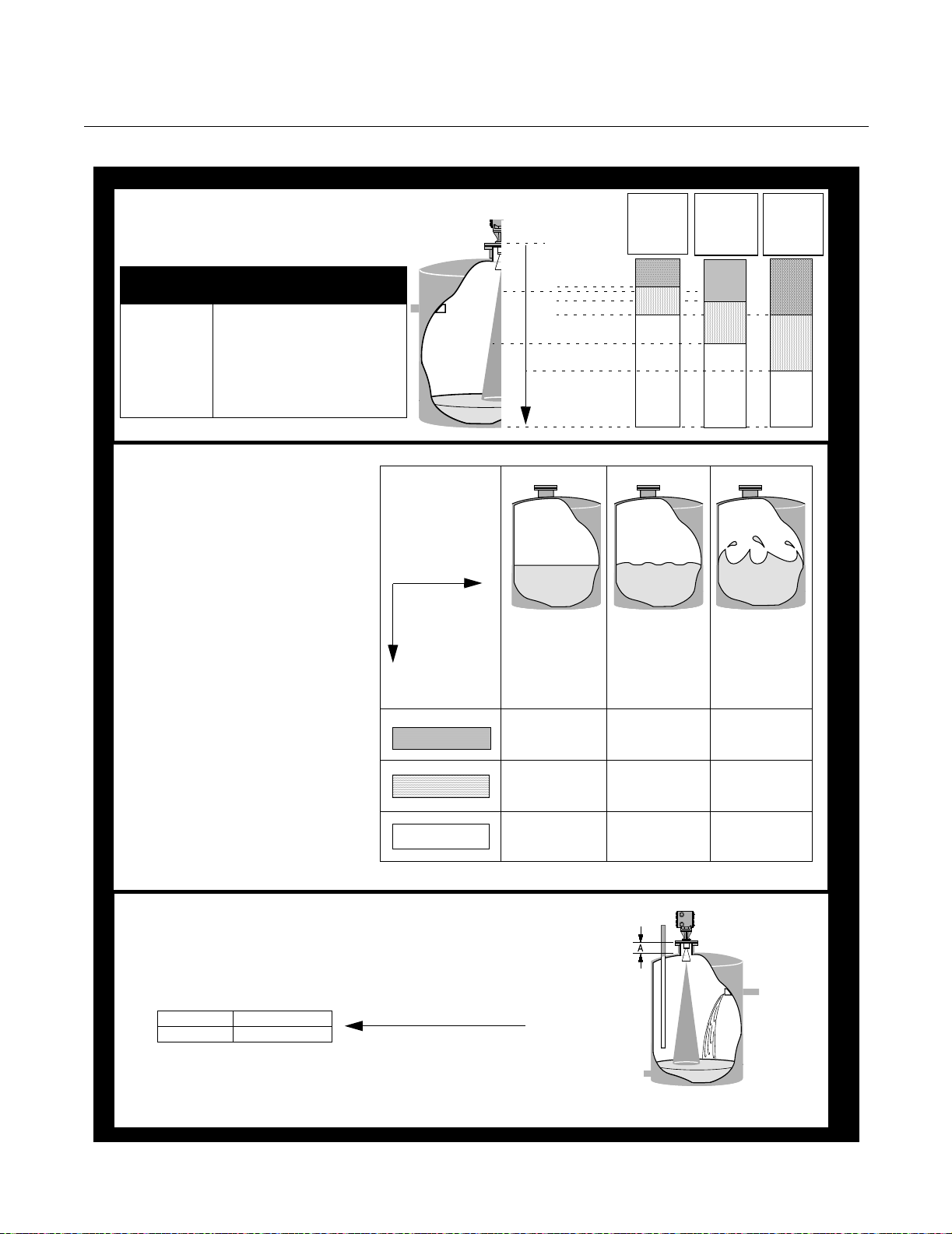
Which Radar Gauge is Best for Your Level Measurement Application?
APEX™ and APEX Sentry™ Radar Gauge
Step 1. Dielectric vs. Distance
Choose the appropriate
shaded region for the application.
Dielectric
Constant, ε
(1)
1.5 - 4.0
4.0 - 10.0 Organic or concentrated acids,
> 10.0 Water-based fluids, alcohols,
(1) Consult Factory when dielectric less than 4
Liquid Examples
r
Hydrocarbons, petrochemicals,
freons, vegetable oils, toluene,
...
organic solvents, ...
dilute acids, acetone, glycols, ...
Step 2. Liquid Surface Quality
Dielectric vs.
(from Step 1.)
Distance Region
Match surface
quality with
shaded region
from Step 1.
Region A
Region B
Region C
Dielectric
Constant
0 m
5 m (16.4 ft)
7,5 m (24.6 ft)
10 m (32.8 ft)
15 m (49.2 ft)
20 m (65.6 ft)
Maximum Distance
30 m (98.4 ft)
CALM
No waves,
storage
Possible
SENTRY-
go to Step 3.
Possible
SENTRY-
go to step 3.
APEX APEX APEX
1.5 to 4.0
Region
Region
Region
Surface Quality
MOVING
Mild rolling,
no splashing,
surface
unbroken
Possible
SENTRY-
go to step 3.
APEX APEX
A
B
C
Dielectric
Constant
4.0 to 10.0
Region
Region
Region
Dielectric
Constant
> 10.0
APEX
Region
Region
Region
(1)
A
B
C
TURBULENT
Heavy
agitation,
vapors, filling,
splashing, or
reactions
A
B
C
Step 3. Tank Geometry
YES APEX Sentry
NO APEX only
NOTE: To meet most telecommunications requirements, the APEX and APEX
Sentry Radar Gauges must be installed on enclosed or vented metal tanks.
However, other tank types may be approved in country of final destination. Refer to
product manual (document number 00809-0100-4731) for detailed information.
Is flange height
(A) 0,5 m (19.6 in)?
— AND —
Is the radar beam free
of any obstructions, such as fill
tubes, baffles, or
exposed agitators?
*
* See “Antenna Selection
Guidelines” on page A-1
LEVEL-APEX_07A, APEX_08A, APEX_011A
1-4
Page 13
Reference Manual
00809-0100-4731, Rev FA
April 2003
APEX™ and APEX Sentry™ Radar Gauge
Components of the
APEX and
APEX Sentry Radar
Gauges
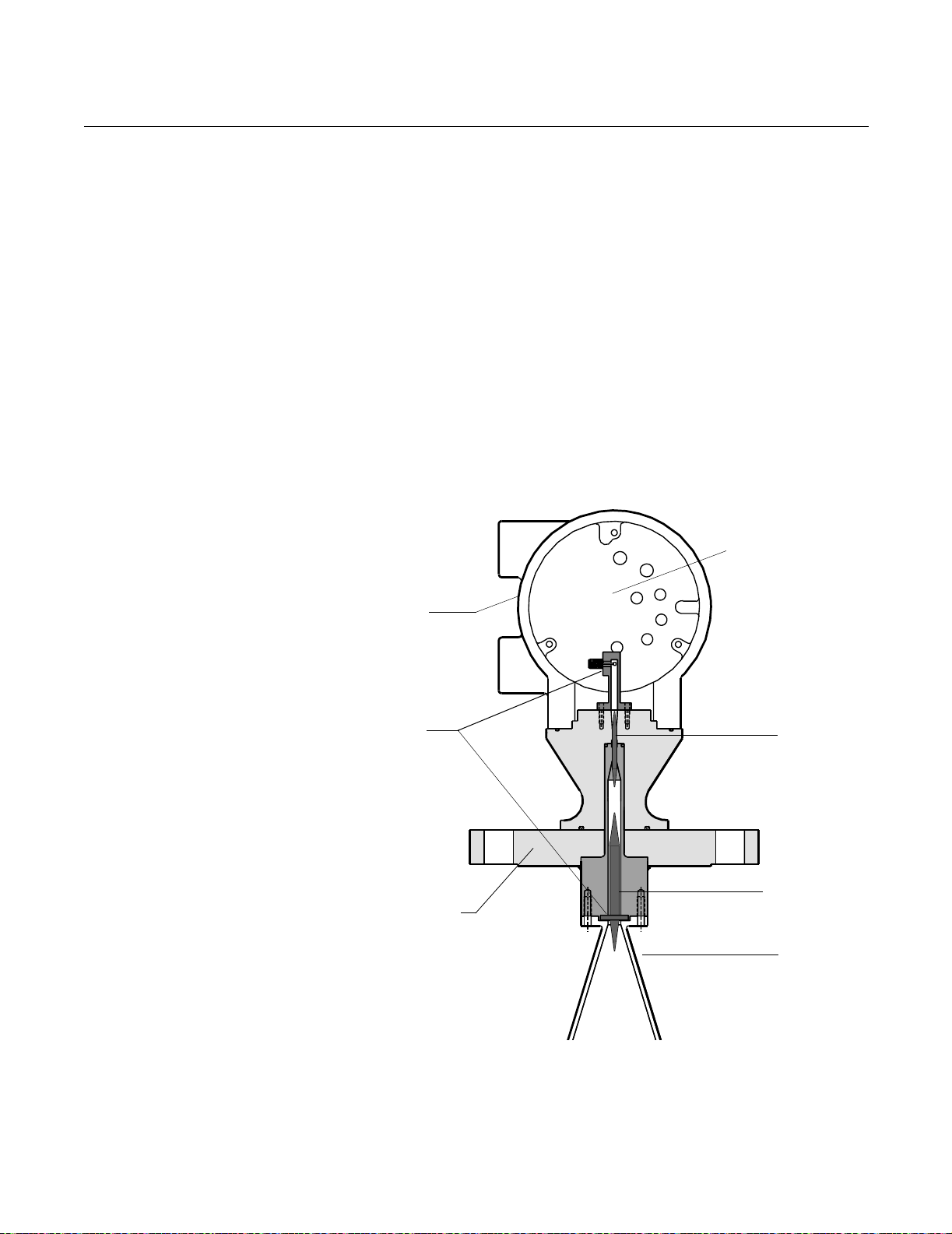
Figure 1-1. Cross-sectional View
of the APEX Radar Gauge
The top of the APEX and APEX Sentry Radar Gauges is an aluminum gauge
housing (see Figure 1-1). The gauge housing includes advanced radar
electronics for signal processing.
The radar electronics is the heart of the gauge. It produces an
electromagnetic wave by using an oscillator that converts direct current (dc)
power into a radar signal. It also receives the return signal.
The radar signal passes from the electronics through a waveguide containing
an alumina ceramic process barrier. The waveguide is the entire path from
the electronics to the antenna.
The antenna is a cone-shaped device made of stainless steel. The antenna
controls the signal beamwidth by helping to keep the radar signal focused on
its target (the product in the tank) so it does not spread out over the entire
vessel and give false echoes. A larger antenna provides a more focused,
narrow beam. (Refer to Appendix A: Reference Data for further information
regarding beamwidth.)
Radar
Electronics
Aluminum
Gauge
Housing
Waveguide
Flange
Alumina
Ceramic
Tef lon
Vapor Seal
Antenna
1-5
Page 14

Reference Manual
00809-0100-4731, Rev FA
April 2003
APEX™ and APEX Sentry™ Radar Gauge
SYSTEM ARCHITECTURE
Figure 1-2. APEX System
Architecture and Display
Options
The output of the APEX and APEX Sentry Radar Gauges is a 4–20 mA
analog signal superimposed with a digital HART signal. As a result, the
primary variable (4–20 mA output) can be configured to represent either level
(APEX and APEX Sentry Radar Gauges) or calculated volume (APEX Radar
Gauge only), with up to three additional variables available through the HART
signal.
In addition to using the HART Communicator, you can view level and volume
variables using an optional Integral Display on the gauge or a Model 751 Field
Signal Indicator as a remote display (see Figure 1-2).
Optional
Integral Display
Level: 5.10 m
4
–
2
0
Level=
5.10 m
mA
/
H
A
R
T
S
i
g
n
a
l
Level: 5.10 m
Model 751 Field
Signal Indicator
HART
Communicator
Control System
Level: 5.10 m
LEVEL-0006B
1-6
Page 15

Reference Manual
00809-0100-4731, Rev FA
April 2003
APEX™ and APEX Sentry™ Radar Gauge
APEX /Hybrid
System Overview
(APEX Radar
Gauge Only)
Figure 1-3. Hybrid System
Option
To maximize the number of available on-line inventory measurements, you
can install and combine an APEX Radar Gauge with a Rosemount
industry-leading pressure transmitter to create a hybrid system (see Figure
1-3). A hybrid system offers the best advantages from both level-based and
pressure-based tank gauging systems:
• Offers all the advantages of the APEX and HTG technologies
• Provides level, volume, mass, and true average
density measurements
• Enhances plant safety since no manual operations are necessary
• Handles traditional problems such as density stratification
For further installation details, please see page 2-1, and refer to the certified
wiring diagrams provided.
APEX
Radar Gauge
Model 3201
HIU
MCAP
Output
HART
Communicator
Addressing Concerns
about Exposure to
The APEX and APEX
Sentry Radar Gauges
Optional
RTD
Optional Pressure Transmitter
RS 485
RS 232
Output
Model 3402 AIM
The Federal Communications Commission has issued a bulletin called
Questions and Answers About Biological Effects and Potential Hazards of
Radio frequency Radiation (OET Bulletin No. 56, Third Edition, January
1989). This document states a recommended power density limit of 5
mW/cm
2
in the frequency range of 1.5–100 GHz. This limit is based on a 1982
ANSI guideline for a time-averaged exposure for humans.
The maximum power density emitted from APEX and APEX Sentry Radar
Gauges is approximately 1.1 mW/cm
When the gauge is mounted in a metal vessel, the emissions external to the
vessel are much lower than the 1.1 mW/cm
2
, which is below the ANSI guideline.
2
measured at the antenna.
For additional information about the safety of radar signals, see Appendix A:
Reference Data.
LEVEL- 2510_04A
1-7
Page 16

Reference Manual
00809-0100-4731, Rev FA
April 2003
APEX™ and APEX Sentry™ Radar Gauge
SERVICE SUPPORT If you have reason to believe that your APEX or APEX Sentry Radar Gauge
may need to be returned for service, please contact a Level Applications
Support Specialist at Rosemount Customer Central (1-800-999-9307). They
will help you determine the best course of action, and may transfer you to
either an Order Administrator or to the Rosemount North American Response
Center (NARC) to arrange the return of your gauge for service or repair.
NOTE
Most radar problems encountered in the field are applications-related, and
can best be dealt with while the gauge is installed.
The representative arranging the return will ask for product model and serial
numbers, and will provide a Return Material Authorization (RMA) number.
The center will also ask for the name of the process material to which the
product was last exposed. If the material to which the product was last
exposed is a hazardous substance as defined by OSHA, a copy of the
required Material Safety Data Sheet (MSDS) for each hazardous substance
identified must be included with the returned products.
The representative arranging your return will detail the additional information
and procedures necessary to return products exposed to hazardous
substances.
1-8
Page 17

Reference Manual
00809-0100-4731, Rev FA
April 2003
APEX™and APEX Sentry™ Radar Gauge
Section 2 Installation
Safety Messages . . . . . . . . . . . . . . . . . . . . . . . . . . . . . . . . . page 2-2
Before You Install . . . . . . . . . . . . . . . . . . . . . . . . . . . . . . . . page 2-3
Considerations . . . . . . . . . . . . . . . . . . . . . . . . . . . . . . . . . . page 2-4
Vessel Characteristics . . . . . . . . . . . . . . . . . . . . . . . . . . . . page 2-7
Process Windows . . . . . . . . . . . . . . . . . . . . . . . . . . . . . . . . page 2-16
Mechanical Installation . . . . . . . . . . . . . . . . . . . . . . . . . . . page 2-20
Mounting the Gauge . . . . . . . . . . . . . . . . . . . . . . . . . . . . . . page 2-21
Electrical Installations . . . . . . . . . . . . . . . . . . . . . . . . . . . . page 2-22
Electrical Considerations . . . . . . . . . . . . . . . . . . . . . . . . . . page 2-24
Wiring Optional Gauge Devices . . . . . . . . . . . . . . . . . . . . page 2-29
Powering Up . . . . . . . . . . . . . . . . . . . . . . . . . . . . . . . . . . . . page 2-33
NOTE
All information included refers to both the APEX Radar Gauge
and the APEX Sentry Radar Gauge unless otherwise stated.
This section contains instructions for installing the APEX and APEX Sentry
Radar Gauges, including gauge mounting, wiring, and field configuration
using the APEX integral display or a HART Communicator.
www.rosemount.com
Page 18

Reference Manual
00809-0100-4731, Rev FA
APEX™and APEX Sentry™ Radar Gauge
April 2003
SAFETY MESSAGES Procedures and instructions in this section may require special precautions to
ensure the safety of the personnel performing the operations. Information that
raises potential safety issues is indicated by a warning symbol ( ). Please
refer to the following safety messages before performing an operation
preceded by this symbol.
Explosions could result in death or serious injury:
Verify that the operating environment of the gauge is consistent with the appropriate
hazardous locations certifications.
Before connecting a HART-based communicator in an explosive atmosphere, make sure
the instruments in the loop are installed in accordance with intrinsically safe or
non-incendive field wiring practices.
Do not remove the gauge cover in explosive atmospheres when the circuit
is alive.
Failure to follow safe installation and servicing guidelines could result in death or
serious injury:
Make sure only qualified personnel perform the installation.
Use the equipment only as specified in this manual. Failure to do so may impair the
protection provided by the equipment.
Do not perform any service other than those contained in this manual unless you are
qualified.
High voltage that may be present on leads could cause electrical shock:
Avoid contact with leads and terminals.
Make sure the main power to the APEX Radar Gauge is off and the lines to any other
external power source are disconnected or not powered while wiring
the gauge.
2-2
Page 19
Reference Manual
00809-0100-4731, Rev FA
April 2003
APEX™and APEX Sentry™ Radar Gauge
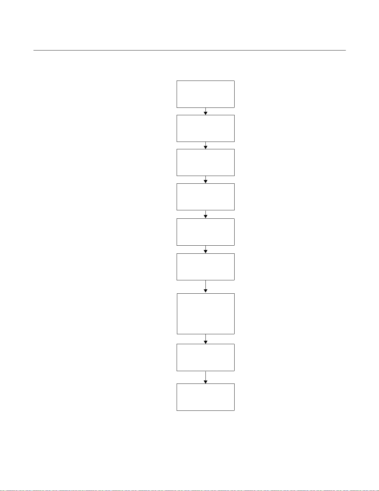
BEFORE YOU INSTALL Follow these steps for proper installation:
Review Installation
Considerations
(see page 2-4)
Check Processor
Switches
(See page 2-22)
Review Electrical
Considerations
(See page 2-24)
Mount Gauge
(See page 2-21)
Wire Gauge
(See page 2-22)
Wire Optional Devices
(See page 2-29)
Make sure covers and
conduit connections
are tight; plug unused
conduit entry
Power Up Gauge
(See page 2-33)
Configure Gauge
(See page 3-1)
2-3
Page 20

Reference Manual
00809-0100-4731, Rev FA
APEX™and APEX Sentry™ Radar Gauge
April 2003
CONSIDERATIONS This section includes information you should consider before installing the
APEX and APEX Sentry Radar Gauges in the field. It includes information on
the following:
• Telecommunications agency requirements
• Unpacking the gauge
• Mounting requirements
• Vessel and process characteristics to consider
For information about configuring the radar gauge using a HART
Communicator, refer to Section 3: Configuration.
Telecommunications
Agency Requirements
Rosemount APEX and APEX Sentry Radar Gauges have been approved for
installation in closed metal tanks, including those that are vented to the
atmosphere. (See "Tank Requirements" below.) Tanks must be closed (or
vented) to contain radar emissions which can otherwise interfere with
aeronautical aviation. Installation shall be done by trained installers. The
radar gauges must be securely bolted to a standard tank flange in strict
compliance with the manufacturer’s instructions.
Failure to properly install the device could constitute an impermissible
modification of the device. In such an event, the responsibility is placed on the
modifying party to ensure compliance with telecommunications regulations,
and Rosemount shall have no liability whatsoever resulting from unauthorized
installation of the device.
Operation Requirements
The use of this device is on a “no-protection, no-interference” basis. That is,
the user shall accept government operations of high-powered radar in the
same frequency band which may interfere with or
damage this device. On the other hand, devices found to interfere
with Government operations will be required to be removed at the user’s
expense.
APEX and APEX Sentry Radar Gauges installed in the United Kingdom
operate between 24.15-26.05 GHz. All other APEX and APEX Sentry Radar
Gauges operate between 24.05 GHz and 26.05 GHz.
In certain countries, the radar gauge must be switched off when opening the
access door to the tank. Any usage in tanks made of non-metallic materials is
prohibited.
2-4
Underground tanks with all exposed surfaces metallized are sufficient to
contain radar emissions.
Tank Requirements
In the United States only, APEX and APEX Sentry Radar Gauges may also
be installed on enclosed or vented concrete tanks with a minimum wall
thickness of 2.5 inches.
In purchasing an APEX or APEX Sentry Radar Gauge, you agree to install the
device in accordance with these conditions.
At the time of this printing, Rosemount Inc. has received the appropriate
telecommunications approval for sale in the countries shown on page A-13.
If you have any questions about what constitutes proper installation, please
contact Rosemount Customer Central at 1-800-999-9307.
Page 21

Reference Manual
00809-0100-4731, Rev FA
April 2003
APEX™and APEX Sentry™ Radar Gauge
Unpacking the APEX and
APEX Sentry Radar
Gauges
Figure 2-1. APEX Radar Gauge
1. Remove the gauge from the shipping container, taking care not to
damage the contents.
2. Place the gauge on its side on a flat surface as in Figure 2-1.
NOTE
Do not stand the radar gauge upright on its antenna. Be careful not to
damage any part of the antenna during bench inspection or installation.
3. Inspect the unit and report any shipping damage to the carrier.
RADAR-003AB
Installation
Considerations
Before you install an APEX or APEX Sentry Radar Gauge, be sure to
consider your specific mounting requirements, vessel characteristics, and
process characteristics. Review the following information to ensure a
trouble-free, safe, and accurate installation.
The gauge has an Installation Category II (Overvoltage Category) with
pollution degree 2 classification.
Process Characteristics Dielectric Constant
Dielectric constant is a measure of a material’s ability to reflect a radar signal.
Materials with dielectric constants below 3.0 reflect only a small fraction of the
radar signal. Therefore, special care must be taken when measuring low
dielectric fluids.
The gauge can measure fluids with a dielectric constant as low as 1.8 if
vessel conditions are favorable. For example, water-based compounds tend
to have high dielectrics (water has a dielectric of approximately 80), while
hydrocarbons are low. In cases with low dielectrics, it is important to verify
that the dielectric is high enough for radar to measure. For information on
dielectric constants when using an APEX Radar Gauge, refer to Table 2-1 on
page 2-6. If you are unable to determine the dielectric constant for your
process, or if you are measuring a process with a dielectric constant lower
than 3.0, contact Rosemount Customer Central at 1-800-999-9307 for
assistance.
2-5
Page 22

Reference Manual
00809-0100-4731, Rev FA
APEX™and APEX Sentry™ Radar Gauge
Table 2-1. Sample list of dielectric constants
Dielectric Constant Ranges for Chemicals Listed
Less Than 1.8 1.8 to 4.0 4.0 to 10.0 10.0 to 15.0 15.0 to 20.0 More than 20.0
carbon dioxide acetylene acetic acid benzyl alcohol ammonia acetone
cyclopentane asphalt bromobutane butyl nitrate butanol ethanol
ethylene benzene butyl alcohol carveol cyclohexanol ethylene glycol
methane butane chlorobenzene creosol diacetone alcohol glycerine
jp4 (military fuel) carbon tetrachloride chloroform dimethyl oxalate dichloro ethane glycol
propane cocaine chlorotoluene ethylene chloride isopropyl alcohol hydrazine
freons cresol hexanol lactic acid hydrogen peroxide
kerosene dibutyl phtalate iodine methylamine hydrogen cyanide
napthalene dichlorobutane methylamine methyl ethyl ketone latex
octane ethylamine phenol nitroglycerin methanol
oleic acid nicotine pyridine sulfur dioxide molasses
petroleum oils phosphorus tripropyl phosphate propanol
stearic acid phosgene vinyl isocyanate sorbitol
styrene sulfur water
sulfur toluene diisocyanate
toluene
vegetable oils
April 2003
Foam and Vapors
Foam may affect the gauge performance because it can reduce the radar
signal being reflected. The effect is highly dependent on the particular
characteristics of the foam. In general, the APEX Radar Gauge reads the top
of the foam if it is sufficiently reflective. The APEX Sentry Radar Gauge is not
for use in applications with foam.
Changing Density, Temperature, or Pressure
The level accuracy is not affected by changes in the density, temperature, or
pressure of the product.
Turbulence or Vortices
The gauge uses advanced signal processing, reducing the effects of
turbulence and vortices. However, the greater the turbulence or vortex the
larger the effect because they disturb the product surface where the signal is
being reflected. With vortices caused by agitators, you need to be aware of
the “swell” effect. That is, the product surface will rise in the vessel when
sufficiently agitated and the radar output will measure this rise. The APEX
Sentry Radar Gauge is not for use in turbulent applications. Refer to Figure
2-18 on page 2-22 for further information.
2-6
Page 23

Reference Manual
00809-0100-4731, Rev FA
April 2003
APEX™and APEX Sentry™ Radar Gauge
Coating, Condensate, or Corrosion
The functionality of the gauge may be affected by coating, condensate, or
corrosion, depending on the type of process in the vessel. When conditions
produce heavy condensation or coating, or when the process is corrosive to
316 SST or alumina ceramic, Rosemount suggests using a process “window”
with the gauge to protect the antenna and waveguide.
VESSEL CHARACTERISTICS
Figure 2-2. Vessel
Characteristics That May Affect
the Level Reading
Mount the gauge where it will have a clear view of the tank surface, but not in
the top center of the vessel (Figure 2-10).
LEVEL-SEETHEPROCESS.TIF
POOR PLACEMENT PREFERRED PLACEMENT
NOTE
When using an APEX Sentry Radar Gauge, it is necessary for 100% of the
beam cone to contact the liquid surface.
Refer to Table 2-2 on page 2-8 for further information.
2-7
Page 24

APEX™and APEX Sentry™ Radar Gauge
Table 2-2. Beamwidth versus
Distance from flange face
to tank bottom
Distance (D)
from gauge
2-in. Antenna 3-in. Antenna 4-in. Antenna
ft (m) ft (m) ft (m) ft (m)
2 (0.6) 0.4 (0.12) 0.2 (0.07) 0.2 (0.06)
4 (1.2) 0.8 (0.25) 0.5 (0.15) 0.4 (0.11)
6 (1.8) 1.2 (0.37) 0.7 (0.22) 0.6 (0.17)
8 (2.4) 1.6 (0.49) 1.0 (0.29) 0.7 (0.22)
10 (3.0) 2.0 (0.62) 1.2 (0.37) 0.9 (0.28)
15 (4.6) 3.0 (0.93) 1.8 (0.55) 1.4 (0.42)
20 (6.1) 4.1 (1.23) 2.4 (0.73) 1.8 (0.56)
25 (7.6) 5.1 (1.54) 3.0 (0.92) 2.3 (0.70)
30 (9.1) 6.1 (1.85) 3.6 (1.10) 2.8 (0.84)
35 (10.7) 7.1 (2.16) 4.2 (1.28) 3.2 (0.98)
40 (12.2) 8.1 (2.47) 4.8 (1.46) 3.7 (1.12)
45 (13.7) 9.1 (2.78) 5.4 (1.65) 4.1 (1.26)
50 (15.2) 10.1 (3.09) 6.0 (1.83) 4.6 (1.40)
55 (16.8) 11.1 (3.40) 6.6 (2.01) 5.1 (1.54)
60 (18.3) 12.2 (3.70) 7.2 (2.20) 5.5 (1.68)
65 (19.8) 13.2 (4.01) 7.8 (2.38) 6.0 (1.82)
70 (21.3) 14.2 (4.32) 8.4 (2.56) 6.4 (1.96)
75 (22.9) 15.2 (4.63) 9.0 (2.75) 6.9 (2.10)
80 (24.4) 16.2 (4.94) 9.6 (2.93) 7.4 (2.24)
85 (25.9) 17.2 (5.25) 10.2 (3.11) 7.8 (2.38)
90 (27.4) 18.2 (5.56) 10.8 (3.30) 8.3 (2.52)
95 (29.0) 19.2 (5.86) 11.4 (3.48) 8.7 (2.66)
100 (30.5) 20.3 (6.17) 12.0 (3.66) 9.2 (2.80)
Radius (r) from Flange Centerline to
Reference Manual
00809-0100-4731, Rev FA
April 2003
Beamwidth Edge
2-8
Page 25
Reference Manual
00809-0100-4731, Rev FA
April 2003
APEX™and APEX Sentry™ Radar Gauge
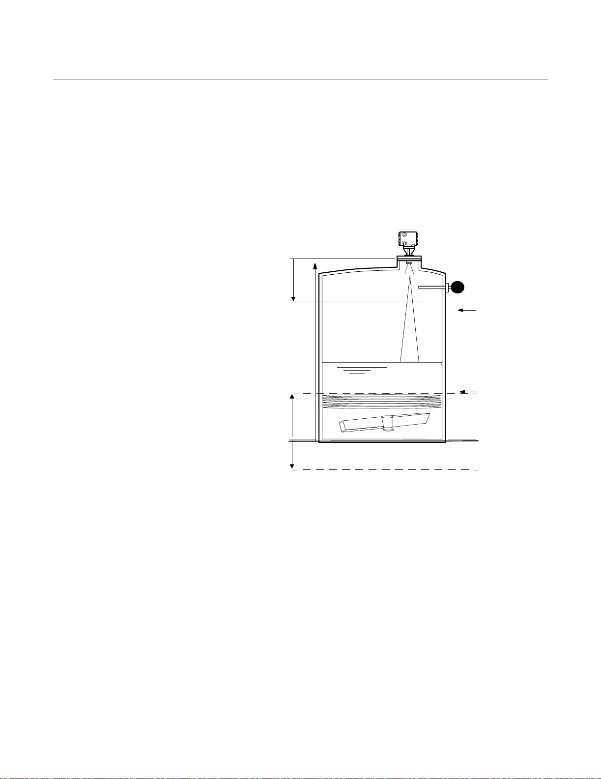
General Vessel
Considerations
Figure 2-3. User-Programmable
“Null” Zones for
APEX and APEX Sentry Radar
Gauges
Heating Coils and Agitators
If the vessel contains heating coils or agitators (see Figure 2-2), they may
create noise when the radar signal bounces off of them. The noise level is
less if the signal contacts a non-flat surface (for example, round pipe, angled
blade, etc.) that causes the signal to scatter rather than directing it back to the
antenna. To avoid these problems, try to make sure that heating coils or
agitators are below the minimum product level or within the null zones (see
Figure 2-3 on page 2-9 and Figure 2-3 on page 2-9).
Upper
Null
Zone
Radar gauge will not
measure above this line.
Reference
Gauge Height
High Level Switch
URV (20 mA)
LRV (4 mA)
Lower
Null
Zone
-19.6 in.
(-0.5 m)
Radar gauge will not measure below this line.
Reference Line
Cables, Floats, Baffles, or Trays
Cables, floats, baffles, or trays can introduce noise into the radar signal. A
vertical cable or rounded surface causes minimal effect because the radar
signal is scattered rather than directed back to the antenna. To reduce the
amount of noise from cables, floats, baffles, or trays, position the gauge such
that the beam will not contact them.
LEVEL-0579A
2-9
Page 26

APEX™and APEX Sentry™ Radar Gauge
Inlet Pipes or Flows
The level reading may be affected by the process flowing into the vessel. To
lessen the effects, mount the radar gauge so the beam signal does not
contact the inlet pipe or flow (Figure 2-2).
Center of tank installations should be avoided, off-center installations are
preferred (Figure 2-4).
Figure 2-4. Example of off
center tank installation.
Reference Manual
00809-0100-4731, Rev FA
April 2003
NOTE
Center of the tank installations should be avoided.
Specific Tank Shapes Spherical Vessel Considerations
Figure 2-5. Spherical vessel
installation
NOTE
Spheres should never have top-center installation options.
EXNEW/COLUMNALIGHN.TIF
SPHEREALIGN_AB.TIF
2-10
Page 27

Reference Manual
00809-0100-4731, Rev FA
April 2003
Figure 2-6. Possible horizontal
vessel mounting options
APEX™and APEX Sentry™ Radar Gauge
Horizontal Vessel Mounting Surface
Horizontal cylinders often only have top-center connection options. If this is
the case, then the end of the antenna should be down into the vessel or
mounted in a widened area such as a manhole cover. Recessing the antenna
into a nozzle is not recommended (Figure 2-6).
APEXNEW_CYLINDERS.TIF
2-11
Page 28
APEX™and APEX Sentry™ Radar Gauge
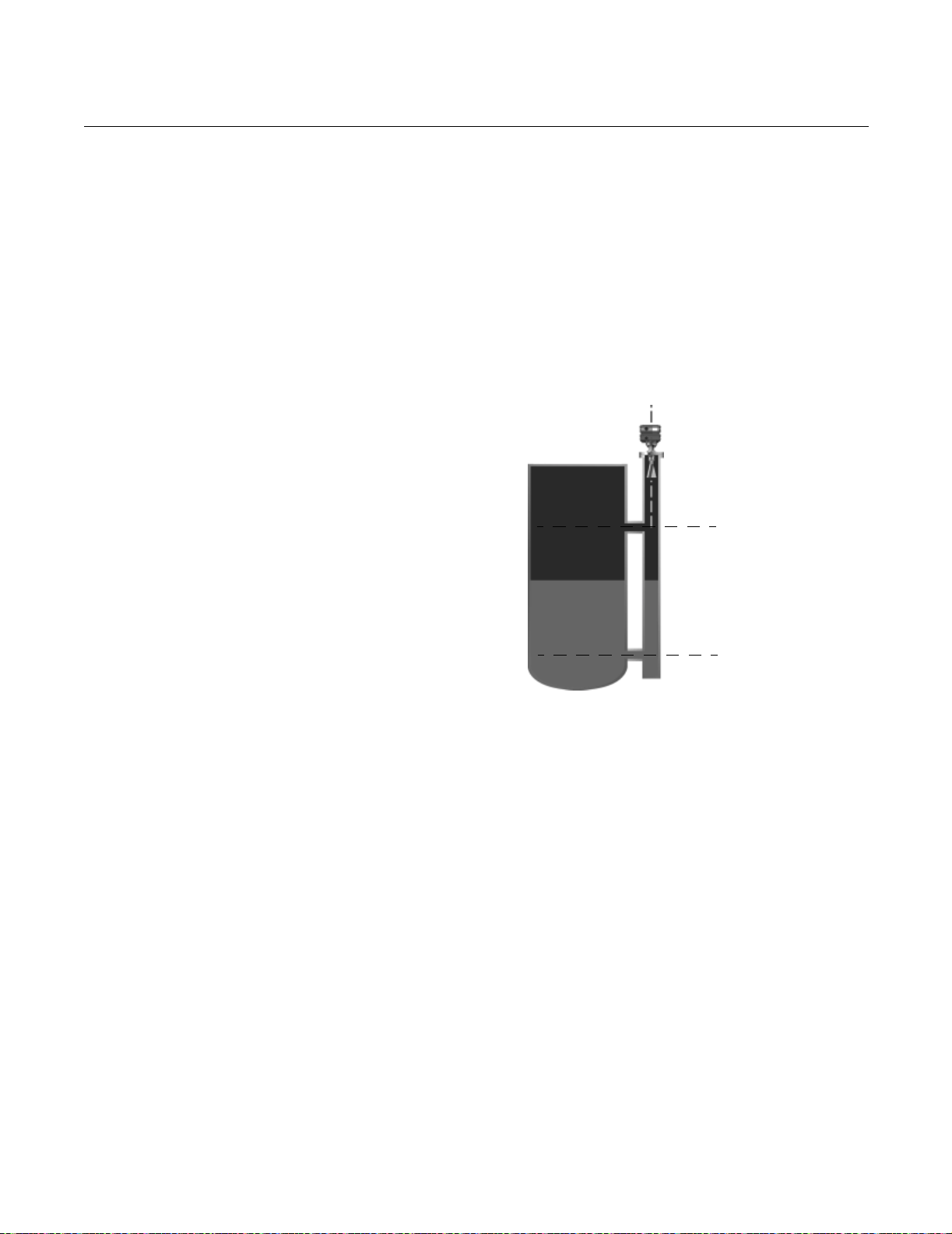
Stilling Well, Bypass Cage, and
Bridle Connection Considerations
Apex and Apex Sentry can be mounted on bypass cages, bridles, and stilling
wells. Non-slotted stilling wells are preferred. If holes must be present, then 1
inch diameter holes approximately 0.5 meters apart are acceptable.
Higher dielectric materials (such as water-based compounds) in a stilling well
or bypass cage will create a strong return signal to the gauge. For this reason
smaller antennas should be used. Lower dielectric materials, (such as
hydrocarbons and solvents) will attenuate the signal so the antenna size
should be as large as possible for the bypass pipe or stilling well.
Figure 2-7. 3 inch or 4 inch
bypass cages can be used.
Reference Manual
00809-0100-4731, Rev FA
April 2003
20mA
4mA
BYPASSCONNECTIONS.TIF
• Stilling wells should be non-slotted. The signal will be stronger because
it is contained within the stilling well. With higher dielectric fluids it is
possible for the signal to be too strong. If this is the case, try using a
smaller antenna.
• At the low end of the well or bridle, especially with joints or bends in
pipes the level or distance may be incorrect due to false reflections. Fill
with fluid to cover the area.
2-12
Page 29

Reference Manual
00809-0100-4731, Rev FA
April 2003
APEX™and APEX Sentry™ Radar Gauge
Nozzle Considerations Non-horizontal Mounting Surface
In most applications, the gauge should be mounted perpendicular to the level
surface. It is acceptable to have the mounting flange up to 2° off from
perpendicular. In applications with low dielectric constants or long measuring
ranges, mounting the radar gauge with the flange horizontal to the product
level becomes more important in order to receive an adequate return signal
(Vessel Characteristics on page 2-7). For more information regarding
mounting considerations, contact Rosemount Customer Central at
1-800-999-9307.
Figure 2-8. Example of
Non-horizontal mounting
APEXNEW/HORIZONTALMOUNTING.TIF
2-13
Page 30

APEX™and APEX Sentry™ Radar Gauge
Tank Nozzle Considerations
Nozzles should be wide open and smooth without any intersecting lines. The
nozzles should not be too long because it will cause a reflection and attenuate
signal. Valves can be used as long as they are open and smooth (no
reducers, lips, or rough edges).
• Nozzles should be open and smooth; no weld lines or ledges should
protrude inside the nozzle, and there should be no restrictions.
• Maximum length of nozzle: 1m for 3 and 4 inch antennas, and 0.3m for
2 inch antennas.
• Full port valves may be used.
• The antenna can be recessed in the nozzle or can extend into the
vessel. However, the end of the antenna should never be even with the
roof of the tank (Figure 2-9).
Figure 2-9. Tank Nozzle
Recommendation
Recommended Not Recommended
Reference Manual
00809-0100-4731, Rev FA
April 2003
Figure 2-10. Example of multiple
nozzle function
Note: Do not install an APEX
Radar Gauge where
there is a T-intersection in the
mounting nozzle.
Note: Antenna must not be even with the roof tank.
APEX_CONEALIGNBA.TIF
The gauge should be mounted so antenna extends 1 inch or more into the
tank, or is recessed into the nozzle by 1 inch or more.
APEX_CONEALIGN.TIF
GASPURGE_AB.TIF
2-14
Page 31

Reference Manual
00809-0100-4731, Rev FA
April 2003
Figure 2-11. Beamwidth vs.
Distance from APEX and APEX
Sentry Radar Gauge to Tank
Bottom
APEX™and APEX Sentry™ Radar Gauge
D
Beam Angle
r
Example: the beam radius (r) at the
bottom of a 10-foot (3.05 m) (D)
vessel would be 0.9 ft (0.28 m) for
a 4-inch antenna.
LEVEL-0038A
Antenna Size Beam Angle
2-in. 22.9°
3-in. 13.7°
4-in. 10.5°
NOTE
A larger antenna yields a tighter and more concentrated signal.
This is an important consideration when using the gauge in various
applications with such characteristics as agitation and/or low
dielectric constants.
2-15
Page 32

APEX™and APEX Sentry™ Radar Gauge
Reference Manual
00809-0100-4731, Rev FA
April 2003
PROCESS WINDOWS The process window typically consists of a PTFE cone that goes below the
gauge antenna and fits in the tank nozzle (see Figure 2-12).
(1)
Condensation
and coating run off of the cone and corrosive processes cannot reach the
antenna. Window installation requires a spool piece that surrounds the
antenna. (See page A-9 for further information.) The length of the spool
piece should allow the end of the antenna to be within 1 inch (25mm) of
the window.
Install the window as shown on page 2-16 and page 2-17.
Figure 2-12. Using a PTFE
Process Window with the APEX
Radar Gauge
Spool Piece
PTFE Window
and Process
Wetted O-ring
APEX Radar Gauge
Metal Gasket
Tank Nozzle
LEVEL-3750A01N
NOTE
Make sure the metal gaskets are installed and the flange bolts are torqued
properly to keep moisture out of the spool piece. Bolts should be re-tightened
24 to 48 hours after initial installation to ensure a tight seal, to prevent
moisture from entering the area, and to meet the pressure needs.
Consult the factory for temperature and pressure limits when using a process
window. See page A-6 for APEX Radar Gauge and process window pressure
and temperature ratings.
Installing without a Process Window
If you are installing the gauge without a process window, refer to Figure
2-13 and follow these steps:
1. Place a gasket on top of the tank flange. (Choose a gasket type
according to process compatibility.)
2. Position the antenna into the tank flange standoff.
3. Check to see that the gauge is positioned so the conduit openings face
the proper direction for wiring.
4. Secure the gauge flange to the tank flange.
5. Tighten the flange bolts when the gauge is properly positioned.
2-16
(1) Further window information is detailed on page 2-16 and page 2-17.
Page 33

Reference Manual
00809-0100-4731, Rev FA
April 2003
Figure 2-13. Diagram for
Installation without a Process
Window
APEX™and APEX Sentry™ Radar Gauge
NOTE
The tightening torque is dependent on the strength of the stud bolts and the
pressure rating of the vessel.
APEX Radar Gauge
Mounting
Bolt/Nut
Customer-Supplied
Gasket
Process
Flange
Installing with a Process Window
If you are installing the gauge with a process window, refer to Figure 2-14
and follow these steps:
NOTE
Make sure the metal gaskets are installed and the flange bolts are torqued
properly to keep moisture out of the spool piece. Bolts should be re-tightened
24 to 48 hours after initial installation.
1. Seat the process O-ring (7) into the groove on the window (6), and center
the window on the process flange without letting the
O-ring slip out of its position in the groove.
2. Make sure that the EMI gasket (8) is seated in the stainless steel window
ring (5), place the window ring over the window, and center a
spiral-wound gasket (4) over the window ring.
3. Center the standoff pipe or spool piece (2) on the flange. Put two of the
bolts (9) in opposite sides and hand tighten. Look inside the spool piece
to verify that the Teflon window is centered on the flange. (See Figure
2-15 on page 2-19.)
4. Once the Teflon window is centered, use the rest of the mounting bolts
and nuts to finish attaching the spool piece to the tank flange. A
misaligned window will severely hinder gauge performance. Tighten
the bolts to 75-100 ft-lbs (102-136 N-m).
NOTE
Visually inspect down the center of the spool to assure the window is
centered.
2-17
Page 34

APEX™and APEX Sentry™ Radar Gauge
Figure 2-14. Diagram for
Installation with a Process
Window
1. APEX Radar
Gauge
Reference Manual
00809-0100-4731, Rev FA
April 2003
9. Mounting Bolts/Nuts
5. SST Window Ring
8. EMI O-Ring
7. Process O-Ring
4. Spiral-wound
Gasket (non-wetted)
2. Standoff Pipe or Spool
Piece (non-wetted)
4. Spiral-wound
Gasket (non-wetted)
6. Teflon Window
Process
O-Ring
3. Process
Flange
Cross-Section of
Installed Process Window
Spiral-wound
Gasket
SST
Window Ring
Teflon
Window
EMI
O-Ring
5. Center the second spiral-wound gasket (4) on top of the standoff
pipe/spool piece.
6. Attach the radar gauge(1) to the standoff pipe or spool piece using the
bolts and nuts as shown. Tighten the bolts to
75-100 ft-lbs (102-136 N-m).
3700_2005A01A
2-18
NOTE
Intermittent purge lines are acceptable. Either purging onto the antenna to
flush away material or onto the window for periodic cleaning. See Figure 5-1
on page 5-3 for more detailed information.
NOTE
When a process window is used, the window and spool piece heights will
need to be incorporated into the Reference Gauge Height and Upper Null
Zone. Refer to the definitions on page 3-8 for more information.
Page 35

Reference Manual
00809-0100-4731, Rev FA
April 2003
Figure 2-15. Window Centering
– Radar Gauge with Installed
Isolation Window
Correctly Installed Incorrectly Installed
APEX™and APEX Sentry™ Radar Gauge
NOTE
It is possible to use a standoff pipe/spool piece supplied by a source other
than Rosemount; however, it is suggested that when the APEX and APEX
Sentry Radar Gauges are mounted, the end of the antenna be no more than
1-inch from the face of the window. For antenna lengths, refer to dimension
“D” in Dimensional Drawings on page A-9.
Tank Nozzle
Common Center
Line for Antenna
and Window
Spool Piece
Correctly Aligned
PTFE Window
and Process
Wetted O-ring
Tank Nozzle
Center Lines for
Antenna and Window
should be the same
Spool Piece
Incorrectly Aligned
PTFE Window
and Process
Wetted O-ring
The APEX and APEX Sentry Radar Gauges are typically factory configured,
so in most situations, gauge adjustments are minimal. To ensure proper
operation, review the following information before installing the gauge. If,
however, your gauge was not configured at the factory, or if you need to
reconfigure the gauge for any reason, please note that the gauge can be
configured on the bench prior to installation or in the field. (Refer to Section 3:
Configuration.)
2-19
Page 36
APEX™and APEX Sentry™ Radar Gauge
MECHANICAL INSTALLATION
Reference Manual
00809-0100-4731, Rev FA
April 2003
Mounting
Considerations
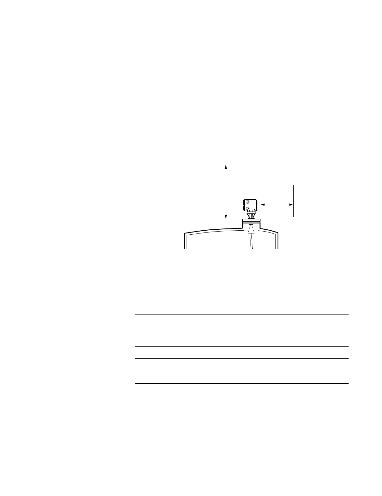
Figure 2-16. APEX and APEX
Sentry Radar Gauge Access
Clearances
Flange Sizes
The radar gauge mounts on the top of a vessel using a 2-, 3-, 4-, or 6-inch
ASME B 16.5 (ANSI) Class (DN 50, DN 80, DN 100, or DN 150) flange.
(Flange size is specified at the time of order.)
Access Clearances
Recommended access clearances for the gauge are shown in Figure 2-16.
18 in. (457mm)
15 in.
(381 mm)
LEVEL-0005A
Wall, Nozzle, or Standoff Clearance
If the radar signal comes in contact with a wall, nozzle, or standoff, it may
cause noise in the level signal. Even though the advanced signal processing
of the radar gauge is designed to filter out this noise, try to keep the noise
level at a minimum by installing the gauge an acceptable distance from
obstructions. To ensure the proper clearance for your vessel height and
beamwidth, review Table 2-2 on page 2-8.
2-20
NOTE
When installing an APEX Sentry Radar Gauge, refer to Figure 2-17 on
page 2-21 for further mounting requirements. 100% of the beam cone must
contact the liquid surface for accurate measurement.
NOTE
Do not mount the radar gauge in the top-center of a vessel.
Off-center mounting is preferred.
Page 37

Reference Manual
00809-0100-4731, Rev FA
April 2003
APEX™and APEX Sentry™ Radar Gauge
MOUNTING THE GAUGE NOTE
If the electronics housing needs to be rotated, do not un-bolt the
adapter-to-housing bolts! Either un-bolt the flange bolts or the
adapter-to-flange bolts and rotate as needed. If the housing is rotated at the
housing-to-adapter connection, the gauge will be irreparably damaged, and
the warranty invalidated. (See Figure 2-17.) Flange bolts are suggested for
use; performance may be affected if adapter bolts are used.
Figure 2-17. Rotating the
Electronic Housing
Housing
Adapter
Flange
Mount the radar gauge vertically on a 2-, 3-, 4-, or 6-inch ANSI Class
(DN 50, DN 80, DN 100, or DN 150) flange on top of the vessel. Make sure
only qualified personnel perform the installation.
DO NOT UN-BOLT HERE
Un-bolt flange bolts or
adapter-to-flange bolts to rotate
(flange bolts are recommended,
as adapter-to-flange bolts may
affect performance)
LEVEL-0021B
NOTE
To ensure long life for your radar gauge, and to comply with hazardous
location installation requirements, tighten covers on both sides of the
electronics housing to achieve metal-to-metal contact.
Refer to Safety Messages on page 2-2 for more information.
2-21
Page 38

APEX™and APEX Sentry™ Radar Gauge
ELECTRICAL INSTALLATIONS
Reference Manual
00809-0100-4731, Rev FA
April 2003
Check Processor
Switches
Electronic boards are electrostatically sensitive. Failure to observe proper
handling precautions for static-sensitive components can result in damage to
the electronic components. Do not remove the APEX or APEX Sentry
electronic boards. The gauges are calibrated with particular boards; swapping
boards will negatively affect accuracy.
Table 2-3.
Switch Bank Description Default Setting Position Settings
Switch 1 4–20 mA Alarm Output High (ON) ON = High, OFF = Low
Switch 2 Security Write Protection Disabled (OFF) ON = Enabled, OFF = Disabled
APEX Radar Gauge Switch Settings
Table 2-4. Analog Output: Standard Alarm Values vs. Saturation Values
Level 4–20 mA Saturation Values 4–20 mA Alarm Value
Low 3.9 mA 3.75 mA
High 20.8 mA 21.75 mA
Table 2-5. Analog Output: NAMUR-Compliant Alarm Values vs. Saturation Values
(option codes C4 or CN)
Level 4–20 mA Saturation Values 4–20 mA Alarm Value
Low 3.8 mA 3.6 mA
High 20.5 mA 21.0 mA
The gauge monitors its own operation. This automatic diagnostic routine is a
timed series of checks repeated continuously. If the diagnostic routine detects
a failure in the gauge, the 4–20 mA output is driven upscale (high) to 21 mA or
downscale (low) to 3.75 mA, depending on the position of Switch 1.
Figure 2-18. Radar Gauge
Processor Switch Settings
Security write protection prevents unauthorized access to configuration data
through the optional integral display or HART Communicator.
4–20 mA Alarm
Output Switch
Microprocessor
Chip
ON
2
1
PROCESSOR BOARD
Security Write
Protection
Switch
LEVEL-0025A
2-22
Page 39

Reference Manual
00809-0100-4731, Rev FA
April 2003
APEX™and APEX Sentry™ Radar Gauge
To set the switches, follow these steps:
1. To access the switch bank on the microprocessor board
(Figure 2-18), remove the cover opposite the terminal side, or remove
the optional integral display (if installed) from the gauge. Do not remove
the gauge cover in explosive atmospheres when the circuit is alive.
2. To set the 4–20 mA alarm output to low, move Switch 1 to the OFF
position. High (ON) is the factory default setting (see Figure 2-18).
3. To enable the security write protection feature, move Switch 2 to the ON
position (top). The OFF (low) option is the factory default setting
(see Figure 4-1).
4. Reinstall the display (if necessary) or replace the cover.
Electrical Considerations Conduit Connections
The electronics housing has two ports for
Adapters are also available for PG 13.5 or CM20 conduit. These connections
are made in a conventional manner in accordance with local or plant electrical
codes. Be sure to properly seal unused ports to prevent moisture or other
contamination from entering the terminal block compartment of the electronics
housing.
3
/4–14 NPT conduit connections.
NOTE
To ensure long life for your radar gauge, and to comply with hazardous
location installation requirements, tighten covers on both sides of the
electronics housing to achieve metal-to-metal contact.
NOTE
In some applications it may be necessary to install conduit seals and arrange
for conduits to drain to prevent moisture from entering the wiring
compartment.
Grounding the Gauge Housing
The electronics housing should always be grounded in accordance with
national and local electrical codes. Use the equipment only as specified in this
manual. Failure to do so may impair the lightning and transient protection
provided by the equipment. The most effective grounding method is to
connect the grounding lug on the gauge directly to earth ground with 1 ohm or
less impedance.
The Internal Ground Connection (Protective Ground Connection), located
inside the FIELD TERMINALS side of the electronics housing, is the Internal
Ground Connection screw. This screw is identified by a ground symbol: .
NOTE
Grounding the gauge case via threaded conduit connection may not provide
sufficient ground.
Refer to Safety Messages on page 2-2 for more information.
2-23
Page 40

APEX™and APEX Sentry™ Radar Gauge
Transient Protection
The APEX and APEX Sentry Radar Gauges include transient protection and
comply with IEC 61000 4-5. Transient protection increases the ability of the
APEX and APEX Sentry Radar Gauges to withstand electrical transients
induced by lightning, welding, or heavy electrical equipment.
External Power Shut-off Switch
The wiring should include an external power shut-off switch or an external
circuit breaker. This device should be located near the gauge.
Reference Manual
00809-0100-4731, Rev FA
April 2003
ELECTRICAL CONSIDERATIONS
APEX and APEX Sentry Radar Gauges accept ¾–14 NPT male conduit
fittings. PG 13.5 and CM 20 adapters are optional. If necessary and
permissible, use flexible conduits close to the gauge.
The gauge output is 4–20 mA superimposed with a HART signal and
shielded, twisted pair wiring is required.
Cable Selection Power supply cables must be suitable for the supply voltage and approved for
use in hazardous areas, where applicable. For instance, in the U.S.,
explosion-proof conduits must be used in the vicinity of the vessel. Use 12
AWG to 18 AWG wire. Using smaller than 18 AWG wire can cause too much
voltage drop to the gauge. Refer to Figure 2-19 on page 2-25 to determine the
correct wire size according to the length of the wire run and available supply
voltage.
Use wire rated for the proper temperature application. For connections in
ambient temperatures above 140 °F (60 °C), use a wire rated for
176 °F (80 °C).
Power Requirements Screw terminals in the radar gauge provide connections for dc or ac power,
secondary inputs and outputs, grounding, and loop testing.
Gauges cannot share common power supplies in a series. Each gauge needs
to have separate wire pairs from the power supply. The loop wires can be
multidropped. Approximately 0.44 amp is required for running the gauge and
1 amp is required for startup. Each APEX and APEX Sentry Radar Gauge
consumes approximately 8 watts.
Avoid contact with leads and terminals.
The operating current will vary depending on power supply size. For example,
the operating current using a 24 vdc supply will equal 0.33 amps:
NOTE
The gauge requires an additional power supply (as indicated in Table 2-6 on
page 2-25) to power the 4–20 mA loop.
NOTE
To ensure long life for your radar gauge, and to comply with hazardous
location installation requirements, tighten covers on both sides of the
electronics housing to achieve metal-to-metal contact.
Refer to Safety Messages on page 2-2 for more information.
2-24
8W
---------- - 0.33amps=
24V
Page 41

Reference Manual
00809-0100-4731, Rev FA
April 2003
Figure 2-19. Main Power Supply
Voltage vs. Wire Length
Required
APEX™and APEX Sentry™ Radar Gauge
Table 2-6. APEX and APEX Sentry Radar Gauge Power Requirements
Power Supply dc ac
Main Power Supply 18–36 V dc 90–250 V ac 50/60 Hz
Loop Power Supply for 4–20 mA 10.5–55 V dc 10.5–55 V dc
45.0
40.0
35.0
18 AWG
30.0
16 AWG
25.0
12 AWG
20.0
Power Supply Voltage in Volts
15.0
300
0
(0)
200
100
(60)
(30)
Approximate Wire Distance in Feet (Meters)
(91)
400
(121)
500
(153)
600
(182)
700
(213)
800
(243)
900
(274)
1000
(304)
Power vs. Distance
Requirements
Hazardous Locations APEX and APEX Sentry feature an explosion-proof housing. Each gauge is
clearly marked with a label indicating the certification it carries. See
Appendix B: Product Certificates for specific approval information.
DC Main Power Supply
with 4–20 mA Loop
Power Supply
Wire the APEX and APEX Sentry Radar Gauges as shown in Figure 2-20,
using an 18–36 V dc main power supply. Loop power is required for the 4–20
mA/HART output. Use a 10.5–55.0 V dc secondary power supply for the 4–20
mA/HART loop output. Refer to Power Requirements on page 2-24 to
determine the power supply voltage required in the control room. Make sure
the main power to the gauge is off and the lines to any other external power
source are disconnected or not powered while wiring the gauge.
LEVEL_APEX06A
Refer to Safety Messages on page 2-2 for more information.
2-25
Page 42

APEX™and APEX Sentry™ Radar Gauge
Figure 2-20. DC Power Supply
Connections with 4-wire
Installation and Separate 4–20
mA Power Supply
Reference Manual
00809-0100-4731, Rev FA
April 2003
10.5–55.0 V dc
Power Supply
Indicator/DCS
APEX Radar
Gauge
(fused)
APEX Radar Gauge with Output Code 2 or
APEX Sentry Radar Gauge
10.5-55 V dc
Supply
18-36 V
18-36 V dc
Main Power
Supply
Indicator/DCS
See note regarding grounding on page 2-23.
dc
Main
NOTE
DC gauges can be configured as a 3 wire gauge if a jumper is used between
the power supply and the loop wiring.
The power terminals are located under a sliding safety cover on the terminal
blocks. This sliding cover exposes only one terminal at a time to guard against
electrical shock. The safety cover must be left on while wiring the radar
gauge. If the cover has been removed, the word “DANGER” appears near the
terminals.
LEVEL-0032, 3700 -1501a01a
2-26
NOTE
When wiring multiple devices, run separate wire pairs to each radar gauge—
do not “daisy chain” or use common return wiring configurations. In other
words, while it is acceptable to multidrop gauges in the 4–20 mA loop, it is not
acceptable to multidrop the power supply loops.
DC Main Power Supply Fuse Size and Type
Be sure to use the proper fuse size and type. Failure to use the appropriate
fuse could result in improper operation or damage to the gauge.
The radar gauge with a dc power supply uses the following
fuse size and type (Rosemount Part No. C53323-0107):
• 2 AG Fuse, 1A, 250 V, Fast Action
Page 43

Reference Manual
00809-0100-4731, Rev FA
April 2003
APEX™and APEX Sentry™ Radar Gauge
NOTE
To ensure long life for your radar gauge, and to comply with hazardous
location installation requirements, tighten covers on both sides of the
electronics housing to achieve metal-to-metal contact.
DC Main Power Supply
with No Loop Power
Supply
Figure 2-21. DC Power Supply
Connections with no loop power
supply
APEX Radar
Gauge
Indicator/DCS
You can also wire the gauge as shown in Figure 2-21, using one 18–36 V dc
power supply capable of supplying 8 watts. Make sure the main power to the
gauge is off and the lines to any other external power source are
disconnected or not powered while wiring the gauge.
NOTE
The APEX draws 1 amp at startup; it is not recommended that a DCS or
channel card be used to power the gauge (the gauge has an operating draw
of 0.375 amp using a 24 vdc supply).
APEX Radar Gauge with Output Code 2
or APEX Sentry Radar Gauge
Add Jumper
Indicator/DCS
Ground Terminal
(fused)
18–36 V
dc Main
Power
Supply
10.5 W
The power terminals are located under a sliding safety cover on the APEX
terminal block. This sliding cover exposes only one terminal at a time to guard
against electrical shock. The safety cover must be left on while wiring the
APEX gauge. If the cover has been removed, the word “DANGER” appears
near the terminals.
Refer to Safety Messages on page 2-2 for more information.
18-36 V
dc Main
Power
See note regarding grounding on page 2-23.
LEVEL-0033, 3700 1501C01A
2-27
Page 44

APEX™and APEX Sentry™ Radar Gauge
NOTE
For all radar gauges with output code 2 (intrinsically safe output), the negative
4–20 mA (HART) terminal is grounded to the electronics housing. Do not use
another ground in the loop. In installations where the intrinsically safe
output (output code 2) will be used, an isolated barrier is required.
NOTE
The APEX will operate on 18–36 V dc at its power terminals. Refer to Power
Requirements on page 2-24 to determine the power supply voltage required
in the control room.
NOTE
To ensure long life for your radar gauge, and to comply with hazardous
location installation requirements, tighten covers on both sides of the
electronics housing to achieve metal-to-metal contact.
Reference Manual
00809-0100-4731, Rev FA
April 2003
AC Main Power Supply
with 4–20 mA Loop
Power Supply
Figure 2-22. AC Power Supply
Connections with Separate 4–20
mA Loop Power
APEX Radar
Gauge
10.5–55.0 V dc
Power Supply
Indicator/DCS
Protective
Earth
(Ground)
Conductor
Wire the gauge as shown in Figure 2-22, using a 90–250 V ac, 50/60 Hz
power supply. Loop power is required for the 4–20 mA/HART output. Use an
additional 10.5–55.0 V dc secondary power supply for the 4–20 mA/HART
loop output. Make sure the main power to the gauge is off and the lines to any
other external power source are disconnected or not powered while wiring the
gauge.
APEX Radar Gauge with Output Code 2
or APEX Sentry Radar Gauge
Ground Terminal
10.5–55.0 V dc
Power Supply
L1
(fused)
90-250 V ac,
50/60 Hz
Main Power
L2
Indicator/DCS
(fused)
Protective
Earth
(Ground)
Conductor
L1
90-250 V ac,
50/60 Hz
Main Power
Supply
L2
LEVEL-0034, 0032AA.EPS
Refer to Safety Messages on page 2-2 for more information.
2-28
Page 45

Reference Manual
00809-0100-4731, Rev FA
April 2003
APEX™and APEX Sentry™ Radar Gauge
The power terminals are located under a sliding safety cover on the terminal
block. This sliding cover exposes only one terminal at a time to guard against
electrical shock. The safety cover must be left on while wiring the gauge. If the
cover has been removed, the word “DANGER” appears near the terminals.
NOTE
For all radar gauges with output code 2 (intrinsically safe output), the negative
4–20 mA (HART) terminal is grounded to the electronics housing. Do not use
another ground in the loop. In installations where the intrinsically safe
output (output code 2) will be used, an isolated barrier is required.
AC Main Power Supply Fuse Size and Type
Be sure to use the proper fuse size and type. Failure to use the appropriate
fuse could result in improper operation or damage to
the gauge.
The gauge with an ac power supply uses the following fuse size and type
(Rosemount Part No. C53323-1104):
3
• 2 AG Fuse,
/8 A, 250 V, Time Delay
WIRING OPTIONAL
GAUGE DEVICES
Model 751 Field
Signal Indicator
NOTE
To ensure long life for your radar gauge, and to comply with hazardous
location installation requirements, tighten covers on both sides of the
electronics housing to achieve metal-to-metal contact.
Optional devices that can be used with the APEX and APEX Sentry Radar
Gauges include the Model 751 Field Signal Indicator, a 3- or 4-wire RTD
(Resistance Temperature Detector), such as the Series 58C, 68, or 78. The
APEX Radar Gauge can also be used in conjunction with a model 3201 HIU
to form a hybrid system.
(APEX Radar Gauge and APEX Sentry Radar Gauge)
If the gauge is to be used with a Model 751 Field Signal Indicator, wire the
gauge using one of the options shown in Figure 2-23.
(If necessary, refer to the Model 751 Field Signal Indicator manual,
00809-0100-4378.) Make sure the main power to the gauge is off and the
lines to any other external power source are disconnected or not powered
while wiring the gauge.
Refer to Safety Messages on page 2-2 for more information.
2-29
Page 46
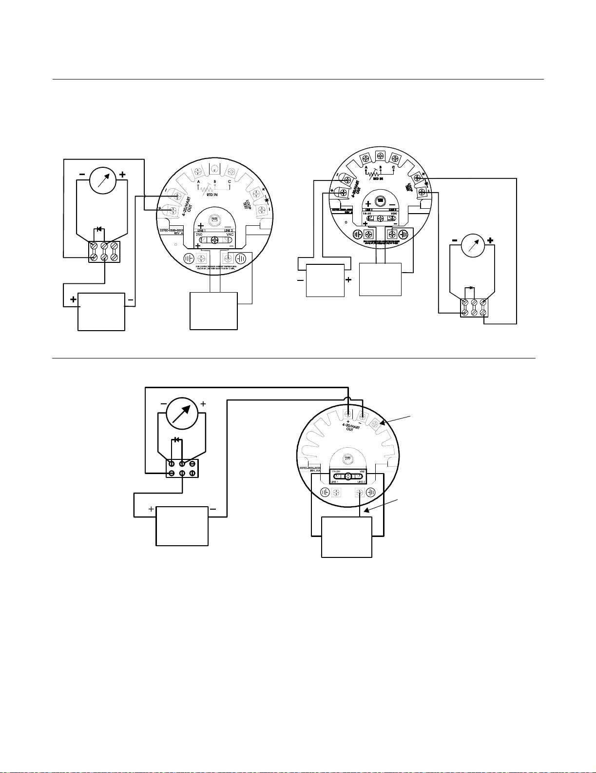
APEX™and APEX Sentry™ Radar Gauge
Figure 2-23. Wire Connection
Options for the Model 751 Field
Signal Indicator
APEX
Model 751 Field
Radar Gauge
Reference Manual
00809-0100-4731, Rev FA
April 2003
APEX
Radar Gauge
10.5-55 V dc,
Power
Supply
REMOTE WIRING FOR MODEL
751 FIELD SIGNAL INDICATOR
10.5-55 V dc
Power
Supply
Model 751 Field
Signal Indicator
90–250 V ac
50/60 Hz
Main Power
10.5-55 V dc
ALTERNATE WIRING FOR MODEL 751
APEX Radar Gauge with Output Code 2
or APEX Sentry Radar Gauge
L1
(fused)
Power
Supply
90–250 V ac,
50/60 Hz
Main Power
Supply
FIELD SIGNAL INDICATOR
Protective Earth
90–250 V ac
50/60 Hz
Main Power
Supply
L2
Model 751 Field
Signal Indicator
Ground Terminal
(Ground)
Conductor
LEVEL-0051/-0035, 3700 -1501D01A
2-30
Page 47
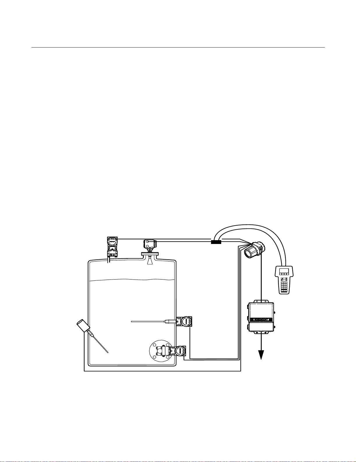
Reference Manual
00809-0100-4731, Rev FA
April 2003
APEX™and APEX Sentry™ Radar Gauge
APEX/Hybrid System
Installation (APEX Radar
Gauge Only)
Figure 2-24. APEX Hybrid
Installation
Model 3001C (PT) Top
Pressure Transmitter Hart
Poll Address: 3
Figure 2-24 and the wiring diagrams in Figures 2-23 are provided to detail the
proper methods of wiring the following tank gauging architectures:
• Figure 2-24: APEX Hybrid System (APEX interfacing with a Model
3201 HIU and Model 3402 AIM architecture)
• Figure 2-24: HART Polling addresses
Based upon the specific type of system you are installing, Figures 2-23
through 2-25 should answer your installation wiring questions. For further
details regarding each component of the system, please refer to each
product’s individual manual.
Product Document Number
• Model 3001C Transmitters 00809-0100-4635
• Model 3201 HIU 00809-0100-4640
• Model 3202 SAM 00809-0100-4646
• Model 3402 AIM 00809-0100-4641
APEX Radar Gauge
Hart Poll Address: 10
Model 3201 (HIU)
Hydrostatic Interface Unit
Hart Poll Address: 0
Water bottom Probe
Hart Poll Address: 5
SMART RTD
TEMPERATURE SENSOR
HART POLL ADDRESS: 4
Model 3001C (PB) Bottom
Pressure Transmitter Hart
Poll Address: 1
(Optional)
Hart
Communicator
Model 3402 (AIM)
Application
Interface Module
RS 232
RS 485
Outputs
OULEVEL-2510A04B
2-31
Page 48

APEX™and APEX Sentry™ Radar Gauge
Reference Manual
00809-0100-4731, Rev FA
April 2003
3- or 4-Wire RTD
(APEX Radar Gauge
Only)
If your vessel is equipped with a 3- or 4-wire platinum 100 ohm RTD, wire the
gauge as shown in Figure 2-25. Make a direct connection from the RTD to the
gauge. The RTD may be mounted a maximum of 500 feet from the gauge.
1. Make sure the main power to the gauge is off and the lines to any other
external power source are disconnected or not powered while wiring the
gauge.
2. Connect three RTD wires directly from the temperature element to the
gauge. Avoid contact with leads and terminals.
3. Wire the sensor across the gauge terminals A and B and the
loop compensation across B and C.
Wires B and C are the same color code; wire A is a different color code.
When using a 4-wire RTD, one wire (the same color as the wire
connected to terminal A) is not used.
For more information about Rosemount RTDs, refer to Product Data Sheet
No. 00813-0100-2654: Series 58C, 68, 68Q, and 78 Temperature Sensors,
Assemblies, and Accessories.
NOTE
If RTD input is to be used, the gauge must have the RTD function enabled.
This can be done at the factory, or it can be done in the field using a Model
275 Hart Communicator or Radar Configuration Tool (see page 3-18).
NOTE
To ensure long life for your radar gauge, and to comply with hazardous
location installation requirements, tighten covers on both sides of the
electronics housing to achieve metal-to-metal contact.
Figure 2-25. Wire Connections
for a 3- and 4-wire RTD
Leave unconnected from circuit
and ground and insulate
Refer to Safety Messages on page 2-2 for more information.
4 Wire RTD
18-35
VDC
3 Wire RTD
Red
WhiteWhiteRedRed
A
White
B
White
C
LEVEL-0036
2-32
Page 49

Reference Manual
00809-0100-4731, Rev FA
APEX™and APEX Sentry™ Radar Gauge
April 2003
POWERING UP Be sure to make all of the APEX or APEX Sentry Radar Gauge connections
before applying power to the system. Check the connections for the power to
the gauge and the power supply for the 4–20 mA loop to be sure they are
correct. Make sure the main power to the gauge is off and the lines to any
other external power source are not powered while wiring the gauge.
Connect the gauge to either 18–36 V dc or 90–250 V ac 50/60 Hz power,
depending on the model selected.
Power consumption by the gauge is approximately 8 watts.
After connecting power, configure the radar gauge using the APEX integral
display (APEX Radar Gauge only), the hand-held Model 275 Hart
Communicator (APEX and APEX Sentry Radar Gauges), or the Radar
Configuration Tools (APEX and APEX Sentry Radar Gauges). The remainder
of this section provides information about field configuration using the optional
integral display.
NOTE
To ensure long life for your radar gauge, and to comply with hazardous
location installation requirements, tighten covers on both sides of the
electronics housing to achieve metal-to-metal contact.
Refer to Safety Messages on page 2-2 for more information.
2-33
Page 50

APEX™and APEX Sentry™ Radar Gauge
Reference Manual
00809-0100-4731, Rev FA
April 2003
2-34
Page 51

Reference Manual
00809-0100-4731, Rev FA
April 2003
APEX™ and APEX Sentry™ Radar Gauge
Section 3 Configuration
Safety Messages . . . . . . . . . . . . . . . . . . . . . . . . . . . . . . . . . page 3-1
Basic Configuration Parameters . . . . . . . . . . . . . . . . . . . . page 3-2
Field Configuration Using the Integral Display Option . page 3-6
Model 275 HART Communication Option . . . . . . . . . . . . . page 3-15
AMS Configuration Tool Option . . . . . . . . . . . . . . . . . . . . page 3-21
Radar Configuration Tool (RCT) Option . . . . . . . . . . . . . . page 3-25
NOTE
All information included refers to both the APEX Radar Gauge
and the APEX Sentry Radar Gauge unless otherwise stated.
The HART Communicator manual provides detailed instructions on the use
and features of the HART Communicator. For information on all the
capabilities of the HART Communicator, refer to the HART Communicator
Product Manual (document 00809-0100-4275).
SAFETY MESSAGES Procedures and instructions in this section may require special precautions to
ensure the safety of the personnel performing the operations. Information that
potentially raises safety issues is indicated by a warning symbol ( ). Please
refer to the following safety messages before performing an operation
preceded by this symbol.
Explosions could result in death or serious injury:
• Verify that the operating environment is consistent with the appropriate
hazardous locations certifications.
• Before connecting a HART-based communicator in an explosive atmosphere,
make sure the instruments in the loop are installed in accordance with
intrinsically safe or non-incendive field wiring practices.
• Do not make connections to the serial port or NiCad recharger jack in an
explosive atmosphere.
Failure to follow safe installation and servicing guidelines could result in death or
serious injury:
• Make sure only qualified personnel perform these procedures.
• Use the equipment only as specified in this manual. Failure to do so may
impair the protection provided by the equipment.
• Do not perform any service other than those contained in this manual unless
you are qualified.
As a matter of routine, the APEX Radar Gauge and all other equipment in your
tank should be shut off prior to entering the tank.
www.rosemount.com
Page 52

APEX™ and APEX Sentry™ Radar Gauge
BASIC CONFIGURATION PARAMETERS
Reference Manual
00809-0100-4731, Rev FA
April 2003
Key Measurement Values
Figure 3-1. Key Measurement
Values
The values given in Figure 3-1 are key factors for installing and configuring
the gauge. Please take a moment to familiarize yourself with the terms used
below. These terms are used throughout this manual.
APEX or APEX
Sentry Radar
Gauge
Upper
Null Zone
Distance
URV
(20 mA)
Reference
Gauge
Process
Level
Empty
Tank
LRV
(4 mA)
Lower Null
Zone
Height
Reference
Line
KEYVALUES.TIF
3-2
Default Values
Upper Null Zone
Lower Null Zone
Minimum Value
Span (URV-LRV)
(1) See “Null Zones” on page 3-6.
(1)
(1)
(1)
19.6 in (0.5 m)
-19.6 in (-0.5 m)
19.6 in (0.5 m)
Reference Gauge Height
The reference line is a common point from which all level measurements are
made. It is usually the bottom of the tank (see Figure 3-1). However, if there is
a stationary object, such as a heat exchanger that is reflective, then that can
serve as the reference line.
Page 53

Reference Manual
00809-0100-4731, Rev FA
April 2003
APEX™ and APEX Sentry™ Radar Gauge
The Reference Gauge Height is the distance between the reference line and
the face of the radar gauge flange, as shown in Figure 3-1. The Reference
Gauge Height is the most critical setting for the radar gauge because it is the
basis for all other calculations. The radar gauge measures the distance to the
product surface and subtracts this value from the Reference Gauge Height to
determine level. To keep level measurements within the stated accuracy
specifications, the Reference Gauge Height must be within the ranges
specified in Appendix A: Reference Data.
If the distance from the reference line (bottom) of the vessel to the gauge is
unknown, you can do one of the following:
• Record the radar gauge level reading and compare it to another known
reference level measurement, such as a hand dip.
Enter the actual level during the configuration process
(see Section 2: Installation). The actual level and distance equals the
Reference Gauge Height. Use the distance reading from the gauge
and the actual level measurement from some other means, add these
values, and input the sum on the Reference Gauge Height.
or
• If the radar gauge is installed when the tank is empty, measure the
Reference Gauge Height (see Figure 3-1) and record the value. You
can determine the Reference Gauge Height in one of
two ways:
– Use the engineering drawing of the vessel to calculate the distance
from the mounting flange surface to the bottom of
the tank.
– If the tank has a flat bottom, use the HART Communicator to set
Distance as the secondary variable and have the radar gauge measure
it. The distance reading displayed on the HART Communicator is the
Reference Gauge Height.
Minimum Clearance to Product Level
The minimum clearance from the gauge flange to the expected maximum
product level must be at least 19.6 inches (50 cm). The gauge cannot
accurately measure levels at less than 19.6 inches (50 cm) from the flange.
Maximum Range
The maximum measuring range for stated accuracies can be found in
Section A: Reference Data.
Upper Range Value (20 mA Point)
When configuring the gauge, you must provide the Upper Range Value
(URV). The URV must be at least 19.6 inches (0.5 m) above the lower range
value.
Lower Range Value (4 mA Point)
When configuring the gauge, the Lower Range Value (LRV) must be provided
and must be at least 19.6 inches (0.5 m) below the upper range value.
3-3
Page 54

APEX™ and APEX Sentry™ Radar Gauge
Volume Parameters
• Refer to “Set Volume Units” on page 3-19 if using a HART
communicator to configure the volume parameters.
• Refer to “Setup - Volume” on page 3-32 if using RCT to configure the
volume parameters.
Special Cases Dish-bottom Tanks, Empty Tank Detection
Radar gauges require a horizontal surface, such as the product surface or the
bottom of the tank, to reflect the signal back up to the antenna. When a
dish-bottom tank is emptied and the surface is no longer horizontal, there may
not be a sufficient amount of signal reflected to get a level reading (see Figure
3-2). If this happens, the radar gauge indicates a lost signal condition unless
the empty tank detection zone is configured.
Figure 3-2. Reflecting the Signal
in a Dish-Bottom Tank
Reference Manual
00809-0100-4731, Rev FA
April 2003
Reference
Gauge Height
URV
(20 mA)
Empty Tank Line
LRV
(4 mA)
APEXNEW/FOCUS.TIF
Reference
Line
The gauge has an empty tank setting designed to handle this situation. To
prevent the gauge from indicating “Lost Signal” in empty tank situations, the
empty tank setting forces it to report “Empty Tank” if the signal is lost when
the level goes below the setting.
3-4
Page 55

Reference Manual
00809-0100-4731, Rev FA
April 2003
Figure 3-3. Reflecting Signal in a
Low Level Tank.
APEX™ and APEX Sentry™ Radar Gauge
Reference
Gauge Height
URV
(20 mA)
Low Level
Tank Line
Empty Tank Line
LRV
(4 mA)
To activate the empty tank feature, use the HART Communicator and set the
Empty Tank parameter to a value greater than zero, but less than 25% of the
Reference Gauge Height (gauges with a serial number over 3217). If the
empty tank parameter is not specified when the gauge is ordered, it will be set
to approximately 10% of the Reference Gauge Height. If the signal is lost
below this setting, the radar gauge will output LEVEL=0 and the mA signal
corresponding to the zero level (usually 4 mA). The message will read “Empty
Tank.”
Reference
Line
APEXNEW/FOCUSAB.TIF
If the signal is lost outside of this configured distance (that is, at higher levels
in the tank), the radar gauge will go into alarm mode and indicate “Lost
Signal” (see Section 5: Hardware and Software Maintenance and
Troubleshooting).
3-5
Page 56

APEX™ and APEX Sentry™ Radar Gauge
Null Zones
The gauge can be programmed to ignore signals that are outside of the
normal operating span of the vessel. There are two user-configurable null
zones—one at the top of the tank and one at the bottom—that, in conjunction
with the gauge height, define the measurement limits for the gauge (see
Figures 3-1 and 2-3). The gauge will ignore any signals reflected outside
these null zones limits.
The upper null zone is measured from the face of the flange down. The
factory default setting for the upper null zone is 19.6 in. (0.5 m). This setting
means that the gauge will ignore all signals within 19.6 in. (0.5 m) of the
gauge flange. Typically, the upper null zone is at least the length of the gauge
antenna and mounting nozzle. The nozzle length must not be the same as
the dimension (see Figure 3-1) or the signal will not generate properly. The
length of the nozzle must be set so the antenna is not even with the roof of the
tank.
The lower null zone is measured from the reference line and may be either a
positive or negative number. The factory default setting for the lower null zone
is –19.6 in. (–0.5 m). This setting allows the gauge to read a level below the
reference line, although it would result in a negative value.
Reference Manual
00809-0100-4731, Rev FA
April 2003
FIELD CONFIGURATION
USING THE INTEGRAL
DISPLAY OPTION
(APEX Radar
Gauge Only)
If the lower null zone is a positive value, the gauge will not read level below
that point. This may be useful if there are any obstacles near the bottom of the
tank that would give a false reading. The overall level reading is still based on
the reference line, however.
The null zone settings can be changed using a HART Communicator and the
“Detailed Setup” procedure as outlined on Figure 3-9 on page 3-16.
NOTE
For information on configuring the APEX Radar Gauge using a Model 275
HART Communicator, refer to page 3-18. The same parameters will need to
be entered regardless of which method you use to configure the gauge.
NOTE
To ensure long life for your radar gauge, and to comply with hazardous
location installation requirements, tighten covers on both sides of the
electronics housing to achieve metal-to-metal contact.
The gauge integral display may be used in explosion-proof areas. Verify that
the operating environment of the gauge is consistent with the appropriate
hazardous locations certifications. You do not need to remove the cover to
operate the integral display.
3-6
To operate the integral display once it has been activated (see page 3-7),
place your finger over one of the optical sensors—ENTER, NEXT, UP, or
DOWN (see Figure 3-4). A light beam reflects off your finger and activates the
sensor and the corresponding function. When you activate a sensor, a red
light confirms that you made contact.
Page 57

Reference Manual
00809-0100-4731, Rev FA
April 2003
Figure 3-4. Optional Integral
Display and Optical Sensors
APEX™ and APEX Sentry™ Radar Gauge
NOTE
An “A” displayed in the lower right corner of the display indicates that the
gauge has gone into alarm mode (see Figure 3-4 for an explanation of error
messages). The “A” will disappear once the unit is out of alarm mode.
Red Indicator Light
ENTER
Level: 5.10
NEXT
NOTE
If the red indicator light blinks constantly, try to clean the glass to see if it
stops blinking.
The sensors provide the following functions:
• The ENTER sensor (left arrow) sets a variable or selects an option.
• The NEXT sensor (right arrow) moves the cursor within the displayed
variable.
• The UP and DOWN sensors change the displayed value of the variable
or option.
Starting the Main Menu To start the main menu, follow these steps
(refer to Figure 3-4 and Figure 3-5):
UP
DOWN
LEVEL/0025A.EPS
1. Press the ENTER sensor.
2. Press the UP sensor.
3. Press the DOWN sensor.
4. Press the NEXT sensor.
5. Press the ENTER sensor again to activate the main menu.
The integral display shows the first variable, Language.
NOTE
If you do not activate any sensors for one minute, the display will
time-out and exit the main menu without saving changes.
3-7
Page 58

APEX™ and APEX Sentry™ Radar Gauge
Figure 3-5. Main Menu Start Up
Sequence
1
5
Language: English
4
Reference Manual
00809-0100-4731, Rev FA
April 2003
2
LEVEL-0025C
3
Setting Configuration
Options
Once you start the main menu, you can set variables and configuration
options. The integral display allows you to set the following:
• Language
• Output units
• Display units
• Reference height
• 4 mA calibration
• 20 mA calibration
The basic procedure for setting configuration options is as follows:
1. Press UP or DOWN to change the displayed value of the variable or
option.
If necessary, press NEXT to move the cursor to the digit you
want to change.
2. Press ENTER to set the variable or select the option and move to the
next option.Configuration changes are not saved until you exit the main
menu using the “Save Changes” selection.
NOTE
When each configuration option first appears on the display, its current value
is displayed below it.
3-8
The menu tree in Figure 3-6 on page 3-10 shows all of the variables and
options you can configure using the integral display. Use the form on the next
page to record the key pieces of information you need to configure the APEX
gauge using the integral display.
Page 59

Reference Manual
00809-0100-4731, Rev FA
April 2003
APEX™ and APEX Sentry™ Radar Gauge
Configuration
Options Form
Use this form to record the five key pieces of information you need before you
begin to configure the gauge using the integral display. Getting this
information ahead of time will help you get your gauge set up and operating
quickly and accurately.
Mark the boxes next to your choices and fill in the requested information on
this form.
1.
Language (select one) ___ English ___ Francais
___ Deutsch ___ Espanol
2.
Output Units (select one) Level Volume
___ ft
___ yd
___ in
3
3
3
3
___ ft ___ m
___ in ___ liters
___ m ___ Imp gal
___ cm ___ US gal
___ mm ___ bbls
Note: Your choice of output units determines the choices available for display units
3.
Reference Gauge
Height:
or
Known Actual Level: _______________________ (circle one: ft, in, cm, mm, m)
Empty Tank Setting: _______________________ (10% of gauge height
4.
4 mA Set Point: _______________________
5.
20 mA Set Point: _______________________
_______________________ (circle one: ft, in, cm, mm, m)
suggested)
3-9
Page 60
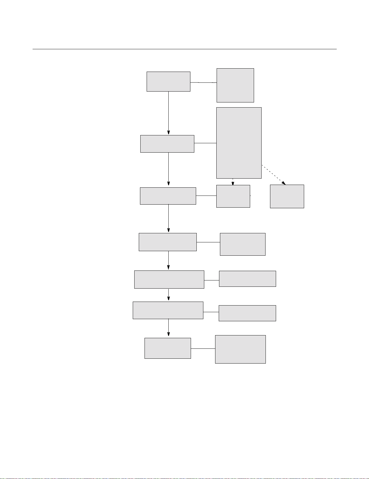
APEX™ and APEX Sentry™ Radar Gauge
Figure 3-6. APEX Radar Gauge
Integral Display Menu Tree
LANGUAGE
OUTPUT UNITS
Reference Manual
00809-0100-4731, Rev FA
April 2003
English
Deutsch
Francais
Espanol
feet
m3
inches
liters
meter
ImGallons
cm
USGallons
millimeter
barrels
ft3
yd3
in3
DISPLAY UNITS
SET REF. HEIGHT
4 mA CALIBRATION
20 mA CALIBRATION
Finished?
level
% level
mA
(Reference) Gauge
Height
Actual Level
xxx [output units]
xxx [output units]
Continue
Save Changes
Abort
volume
% volume
mA
3-10
Page 61

Reference Manual
00809-0100-4731, Rev FA
April 2003
APEX™ and APEX Sentry™ Radar Gauge
Setting the Language
The first variable displayed is Language. Language options include English,
Deutsch, Français, and Español. To set the language:
1. Press UP until the display shows the language you want to use.
2. Press ENTER to set the language.
The menu then displays the Output Units option.
Setting the Output Units
Output unit options include level units and volume units. Level units are feet
(feet), inches (inches), meters (meter), centimeters (cm), and millimeters
(millimeter). Volume units are cubic meters (m3), liters (liters), Imperial
Gallons (ImGallons), U. S. Gallons (USGallons), barrels (barrels), cubic feet
(ft3), cubic yards (yd3), and cubic inches (in3).
NOTE
Volume output units should be selected only if tank type (Tnk Typ) Volume
Geometry has been configured using the HART Communicator (refer to
page 3-18). To display accurate volumetric units, the tank dimensions and
volume equations or a strapping table must be configured in APEX memory
using the HART Communicator.
NOTE
If volume is the desired output, the gauge must first be configured in level
units (see “Setting the Reference Gauge Height” on page 3-12).
To configure the unit for volume output, refer to page 3-18.
To set the output units:
1. Press UP until the display shows the output units option you want to use.
2. Press ENTER to set the output units.
The menu then displays the Display Units option.
Setting the Display Units
The integral display has two display lines (see Figure 3-4). The display for the
upper line can be selected via the integral display itself. The lower line scrolls
through a series of options. It is programmed using the HART Communicator
(refer to page 3-18) or is pre-configured at the factory.
Display unit options for the upper line are level,% level, and mA if level units
were selected for output units.
Display unit options for the upper line are volume,% volume, and mA if
volume units were selected for output units.
3-11
Page 62

APEX™ and APEX Sentry™ Radar Gauge
To set the display units:
1. Press UP until the display shows the display units option you want to
use.
2. Press ENTER to set the display units.
The menu then displays the Reference Height option.
NOTE
The gauge can output up to four variables via the HART Signal.
Setting the Reference Gauge Height
The Reference Height options are Reference Gauge Height or Actual Level.
The “Actual Level” option should be used only when there is a definite target
for signal reflection. Flat-bottom tanks and flat, horizontal liquid surfaces
reflect well. Slanted or turbulent surfaces may not provide sufficient reflection.
The Reference Gauge Height is the most critical setting for the gauge
because it is the basis for all other calculations—choose it carefully!
Reference Manual
00809-0100-4731, Rev FA
April 2003
Figure 3-7. Reference Gauge
Height
Reference Gauge Height
Actual Level
Reference Line
LEVEL-0005A
NOTE
The Reference Gauge Height must be set in level (linear) units. If you want
volume output units on the integral display, you must first select level units,
set the Reference Height, null zones, and empty tank settings and save the
changes. You may then re-enter the menu and choose the desired volume
display units.
Set the Reference Gauge Height:
NOTE
The empty tank setting must be less than or equal to 25% of the gauge height.
When changing from a large gauge height to a smaller gauge height, it may
be necessary to first change the empty tank setting to a smaller value using
the Model 275 HART Communicator.
3-12
Page 63

Reference Manual
00809-0100-4731, Rev FA
April 2003
APEX™ and APEX Sentry™ Radar Gauge
1. Press UP until the display shows the reference height option you want to
use.
2. Press ENTER to select (reference) Gauge Height or Actual Level.
If the dimension from the reference line (bottom) of the vessel to the
gauge is unknown, do one of the following:
• • If the tank is empty and has a flat bottom, enter “0” for the
actual level.
or
• • Use the vessel drawing to determine the Reference Gauge Height.
or
• • Use another known reference level measurement, such as a hand
dip, and enter that value for Actual Level. The gauge will then calculate
its height.
3. Press NEXT to move the cursor to the digit you want to change.
4. Press UP or DOWN to change the value.
5. Repeat steps 3 and 4 for each digit.
6. When finished, press ENTER to set the value of the Reference Gauge
Height or Actual Level.
The menu will continue to the next step.
Setting the 4 mA Calibration
The 4 mA calibration variable is expressed in terms of the configured output
units. To receive a 20 mA calibration on the Integral Display Option the loop
must be powered. To set the 4 mA calibration:
1. Press NEXT to move the cursor to the digit you want to change.
2. Press UP or DOWN to change the value.
3. Repeat steps 1 and 2 to change the next digit.
4. When finished, press ENTER to set the desired 4 mA calibration.
The menu then displays the 20 mA calibration variable.
3-13
Page 64
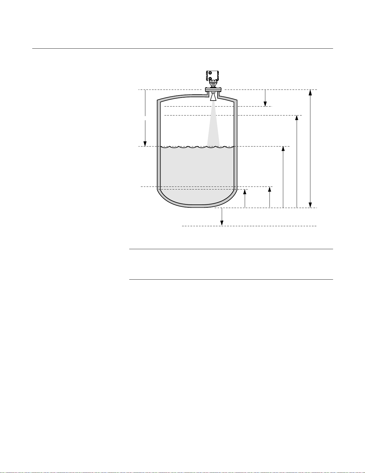
APEX™ and APEX Sentry™ Radar Gauge
Figure 3-8. Key Measurement
Values
APEX Radar Gauge
Reference Manual
00809-0100-4731, Rev FA
April 2003
Distance
Lower Null Zone
Upper Null Zone
(Min. 19.6 in.)
Process Level
LRV
(4 mA)
Empty
Tan k
Reference
Gauge Height
URV(20 mA)
Reference
Line
LEVEL-0005B
Setting the 20 mA Calibration
NOTE
When setting the 20 mA point, be sure to set it at least 19.6 in. (0.5 m) from
the flange face and below the upper null zone. The gauge cannot accurately
measure the product level closer than 19.6 inches.
3-14
The 20 mA calibration variable is expressed in terms of the configured output
units. To receive a 20 mA calibration on the Integral Display Option the loop
must be powered. To set the 20 mA calibration:
1. Press NEXT to move the cursor to the digit you want to change.
2. Press UP or DOWN to change the value.
3. Repeat steps 1 and 2 to change the next digit.
4. When finished, press ENTER to set the desired 20 mA calibration.
The menu then displays the message “Finished?”
Page 65

Reference Manual
00809-0100-4731, Rev FA
April 2003
APEX™ and APEX Sentry™ Radar Gauge
Exiting the Main Menu To save the configuration information and exit the main menu:
1. Make sure the “Save Changes” message is displayed
(press UP or DOWN if necessary).
2. Press ENTER.
To make additional changes, press UP or DOWN to display the message
“Continue.”
• Press ENTER if you want to repeat the steps for changing each of the
variables and configuration options.
or
• To go to a specific option, continue pressing ENTER until you reach the
option you want to change.
To discard the configuration changes:
1. Press UP or DOWN to display the message “Abort.”
2. Press ENTER.
MODEL 275 HART COMMUNICATION OPTION
Commissioning on the
Bench With HART
Commissioning consists of testing the transmitter and verifying transmitter
configuration data. The APEX and APEX Sentry Radar Gauge can be
commissioned either before or after installation. Commissioning the
transmitter on the bench before installation using a Model 275 HART
Communicator or AMS ensures that all transmitter components are in working
order.
To commission on the bench, connect the transmitter and the HART
Communicator. Make sure the instruments in the loop are installed according
to intrinsically-safe or nonincendive field wiring practices before connecting a
communication in an explosive atmosphere. Connect HART Communicator
leads at any termination point in the signal loop. For convenience, connect
them to the terminals labeled “COMM” on the terminal block. Connecting
across the “TEST” terminals will prevent successful communication. Avoid
exposing the transmitter electronics to the plant environment after installation
by setting all transmitter jumpers during the commissioning stage on the
bench.
For 4–20 mA transmitters, the power supply must provide 10.5 to 42.4 V dc at
the transmitter, and a meter to measure output current. To enable
communication, a resistance of at least 250 ohms must be present between
the HART Communicator loop connection and the power supply. Do not use
inductive-based transient protectors with the APEX and APEX Sentry Radar
Gauge.
When using a HART Communicator, any configuration changes made must
be sent to the transmitter by using the “Send” key (F2). AMS configuration
changes are implemented when the “Apply” button is clicked.
For more information on the Model 275 HART Communicator see document
00275-8026-0002.
3-15
Page 66

00809-0100-4731, Rev FA
APEX™ and APEX Sentry™ Radar Gauge
Figure 3-9. HART Communicator Menu Tree for the APEX and APEX Sentry Radar Gauges
Reference Manual
April 2003
Online Menu
1.DEVICE SETUP
2. PV
3. AO
4.LRV
5.URV
NOTE
The Review Menus list all of
the information stored in the
radar gauge. This includes
device information,
measuring element, signal
condition, output condition, and
software revision.
3-16
1.PROCESS
VAR IAB LE
2.DIAGNOSTICS
AND SERVICE
3.BASIC SETUP
4.DETAILED SETUP
5.REVIEW
MENUS
1.VARIABLE MAPPING
2.Level
3.PV % rnge
4.A01
5. Dist
6.Vol *
7.Int. Temp
8.Temp *
9.RTD *
— St Vol *
— Loop Vlt
— SNR
— Targ Str
1.TEST DEVICE
2.Loop Test
3.D/A Trim
1. Tag
2.TRANSMITTER UNITS
3.RERANGING
4.Gauge Ht
5.RTD Usage *
6.EmpTank
1.DEVICE
INFORMATION
2.LCD DISPLAY
3.VOLUME
GEOMETRY *
4.SIGNAL
CONDITION
5.OUTPUT
CONDITION
6.THRESHOLD
SETTING
1.Variable Re-map
2.PV is
3.SV is
4.TV is
4 4V is
1.STATUS
2.Master Reset
1.Lev Units
2.Vol Units *
3.Tmp Units
1.Apply Values
2.Range Values
3.PV % Range
1.Distributor
2.Model
3.Dev id
4. Tag
5.Date
6.Write Protect
7.Descriptor
8.Message
9.REVISIONS
- CONSTRUCTION MATLS
1.Current
2.Pct Rng
1.LINE 1
2.LINE 2
3.LANGUAGE
1.TnkTyp
2.Diametr
3.LthOrHt
4.STRAPPING TABLE
(see note)
5.VOLUME COEFFIC
1.PV LRV
2.PV URV
3.PV % rnge
4.PV Damp
5.UprNlZ
6.LowNlZ
1.ANALOG OUTPUT
2.HART OUTPUT
1.Threshold Units
2.Threshold Range
3.Threshold Snapshot
3. PV
1.Status Group 1
2.Status Group 2
3.Status Group 3
4.Status Group 4
5.Status Group 5
6.Status Group 6
7.Status Group 15
8.Status Group 16
9.Status Group 17
— Status Group 18
— Status Group 19
1.Current
2.PctRange
3.Level
4.Distance
5.Volume *
6.Int Temp
7.Temp *
8.RTD Ohms *
— English
— German
— French
— Spanish
To enable volume calculations based on
a strapping table, the “strap table” option
must be selected for tank type.
1.PV AO
2.PV AO ALRM TYP
3.Loop test
4.D/A trim
5.Scaled D/A trim
1.Poll addr
2.Num req preams
3.Burst mode
4.Burst option
Do not go into “Threshold Setting” unless
specifically directed to do so by a Rosemount
Service Representative.
9.Std Volume *
— Loop Vlt
— SNR
— TargStr
1. K0
2. K1
3. K2
4. K3
5. K4
6.Std Temp
NOTE:
* Selections in italics
are not available with the APEX
Sentry Radar Gauge
NOTE
Indicates whether error
messages are active. Refer to
“Alarm and Diagnostic
Messages” on page 5-3 for
assistance.
1.Flange Type
2.Matrl
3.Meter
4.Antenna
5.Barrier
1.Universal Rev
2.Fld Dev Rev.
3.Software Rev.
1.Strap table
2.Ver Cylinder
3.Hor Cylinder
4.Ver Bullet
5.Hor Bullet
6.Sphere
7.None
1.Entries Used
2.Max Entries
3.Lvl0
4.Vol0
5.Lvl1
6.Vol1
7.Lvl2
8.Vol2
9.Lvl3
— Vol3
— Lvl4
— Vol4
—Lvl9
— Vol9
Page 67

Reference Manual
00809-0100-4731, Rev FA
April 2003
APEX™ and APEX Sentry™ Radar Gauge
Setting the Loop to
Manual
Whenever sending or requesting data that would disrupt the loop or change
the output of the transmitter, set the process application loop to manual. The
HART Communicator will prompt you to set the loop to manual when
necessary. Acknowledging this prompt does not set the loop to manual. The
prompt is only a reminder; set the loop to manual as a separate operation.
Wiring Diagrams Bench Hook-up
Connect the bench equipment, and turn on the HART Communicator by
pressing the ON/OFF key. The HART Communicator will search for a
HART-compatible device and indicate when the connection is made. If the
HART Communicator fail to connect, it indicates that no device was found. If
this occurs, refer to Section 5: Hardware and Software Maintenance and
Troubleshooting.
Field Hook-up
Signal point may be grounded at any point or left ungrounded.
Construction Materials 1, 4, 1, –
Device Information 1, 4, 1
Diameter (APEX Radar Gauge Only) 1, 4, 3, 2
Display Language 1, 4, 2, 3
Display Line 1 1, 4, 2, 1
Display Line 2 1, 4, 2, 2
Empty Tank 1, 3, 6
Length or Height (APEX Radar Gauge Only) 1, 4, 3, 3
Level Units 1, 3, 2, 1
Loop Test 1, 2, 2
Lower Null Zone 1, 4, 4, 6
Lower Range Value (LRV) (4 mA) 1, 3, 3
Master Reset 1, 2, 1, 2
Poll Address 1, 4, 5, 2, 1
Primary Variable 1, 1, 1, 1
Process Variable Damping 1, 4, 4, 4
Range Values 1, 3, 3, 2
Reference Gauge Height 1, 3, 4
Strapping Table (APEX Radar Gauge Only) 1, 4, 3, 4
Ta g 1, 3, 1
Tank Type (APEX Radar Gauge Only) 1, 4, 3, 1
Temperature Units 1, 3, 2, 3
Upper Null Zone 1, 4, 4, 5
Upper Range Value (URV) (20 mA) 1, 3, 3
Variable Remapping 1, 1, 1, 1
Volume Coefficient (K Constants) (APEX Radar Gauge Only) 1, 4, 3, 5
Volume Units (APEX Radar Gauge Only) 1, 3, 2, 2
Function HART Fast Key
3-17
Page 68

APEX™ and APEX Sentry™ Radar Gauge
Reference Manual
00809-0100-4731, Rev FA
April 2003
Connections and
Hardware
The HART Communicator exchanges information with the APEX and APEX
Sentry Radar Gauges from the control room, the instrument site, or any wiring
termination point in the loop. The HART Communicator should be connected
in parallel with the gauge. Use the loop connection ports on the rear panel of
the HART Communicator. The connections are non-polarized.
Do not make connections to the serial port or NiCad recharger pack in an
explosive atmosphere.
Using a Model 275 HART Communicator
NOTE
Remember, when using a Model 275 hand held communicator, you must
send the data before configuration changes will take effect.
NOTE
As a matter of routine, shut off the APEX Radar Gauge and all other
equipment before you enter the tank.
To configure the APEX and APEX Sentry Radar Gauges to report LEVEL
(analog output is linear to level) with the gauge wired as in Figure 3-6 on
page 3-10, connect the Model 275 as shown.
Set Transmitter Units Set transmitter units:
HART Comm 1, 3, 2, 1
•ft
•m
•in
•cm
•mm
Set Reference
Gauge Height
HART Comm 1, 3, 4
When setting the Reference Gauge Height, keep in mind that this value is
used for all measurements performed by the APEX. (Refer to “Setting the
Reference Gauge Height” on page 3-12.)
Set 4 and 20 mA Points When setting the range values, it is possible to enter the values directly, or to
HART Comm 1, 3, 3
Volume Configuration
(APEX Radar
Gauge Only)
Refer to “Safety Messages” on page 3-1 and for more information.
3-18
use actual values. Keep in mind that the 20 mA point must be at least 19.6
inches below the flange face.
NOTE
The primary variable must be set to level (factory default).
To configure the gauge to report ACTUAL VOLUME (analog output is linear
with volume) set transmitter units and Reference Gauge Height in level units
as detailed above. The Reference Gauge Height must be set in linear units for
the gauge to be able to read volume.
Page 69

Reference Manual
00809-0100-4731, Rev FA
April 2003
APEX™ and APEX Sentry™ Radar Gauge
Set Volume Units You may choose one of the following:
HART Comm 1, 3, 2, 2
• Gallons (gal)
• Liters (L)
• Imperial Gallons (Impgal)
• Cubic Meters (cum)
• Barrels (bbl)
• Cubic Feet (cuft)
• Cubic Inches (cuin)
• Cubic Yards (cuyd)
Set Primary Variable Select volume for volume measurements.
HART Comm 1, 1, 1, 1
Set Range Values
(4 and 20 mA points)
HART Comm 1, 3, 3
When setting the range values, it is possible to enter the values directly or to
have the gauge read the values. If values are to be read by the gauge, set the
desired tank type first.
Choose Tank Type Choose a tank with a standard shape, or select the strapping option. Standard
HART Comm 1, 4, 3, 1
shapes: Vertical Cylinder, Horizontal Cylinder, Vertical Bullet, Horizontal
Bullet, or Sphere. (If primary variable is level, select “None”). If your tank is
not one of the above, or if you have strapping table information, select “Strap
Table.”
Enter Tank Dimensions If a standard tank shape was chosen, enter the diameter and length
HART Comm 1, 4, 3
Enter Strapping
Table Information
HART Comm 1, 4, 3, 4
(1)
(or height) for the tank.
First tell the gauge how many entries you will have; the more entries you
have, the better the gauge will be able to calculate the volume. The maximum
number of strapping points you can enter is 10.
Next, input the actual level and volume points, starting at the bottom of the
tank. It may be desirable to use most of the points in the areas of the tank that
are the least “straight.” See Figure 3-10. Suggestion: Set first entry at zero
level and zero volume to enable the gauge to track volume over the entire
range.
(1) If tank type is strapping table
3-19
Page 70

APEX™ and APEX Sentry™ Radar Gauge
Figure 3-10. Tank Bottom
Strapping Points
Actual tank bottom may look like this.
Using only 3 strapping points results in a level-to-volume
profile that is more angular than the actual shape.
Reference Manual
00809-0100-4731, Rev FA
April 2003
Using 6 of the points at the bottom of the tank yields a
level-to-volume profile that is similar to the actual tank bottom.
Standard Volume (Apex
Radar Gauge Only)
If standard volume is desired, an RTD must be installed and wired to the
APEX Radar Gauge. First, configure the gauge for actual volume as outlined
in the previous section and configure standard volume as the
secondary variable.
Enable RTD Input Enables the radar gauge to use the RTD input.
HART Comm 1, 3, 5
Enter Volume
Coefficients
HART Comm 1, 4, 3, 4
Volume coefficients (K-Constants) are used to determine how temperature
changes affect volume measurements. If you do not know K-Constants for
your process and would like to measure standard volume, contact Rosemount
Customer Central at 1-800-999-9307 for further assistance.
LEVEL-APEX_05A
3-20
Page 71

Reference Manual
00809-0100-4731, Rev FA
April 2003
AMS CONFIGURATION TOOL OPTION
APEX™ and APEX Sentry™ Radar Gauge
Basic Setup
Figure 3-11. Basic Setup
Example
Right click on the device and select “Configuration Properties” from the menu.
Select the Basic Setup tab, to enter Tank, Process Input, and Device
information.
APEX/AMS/APEX_AMS_01A.TIF
3-21
Page 72
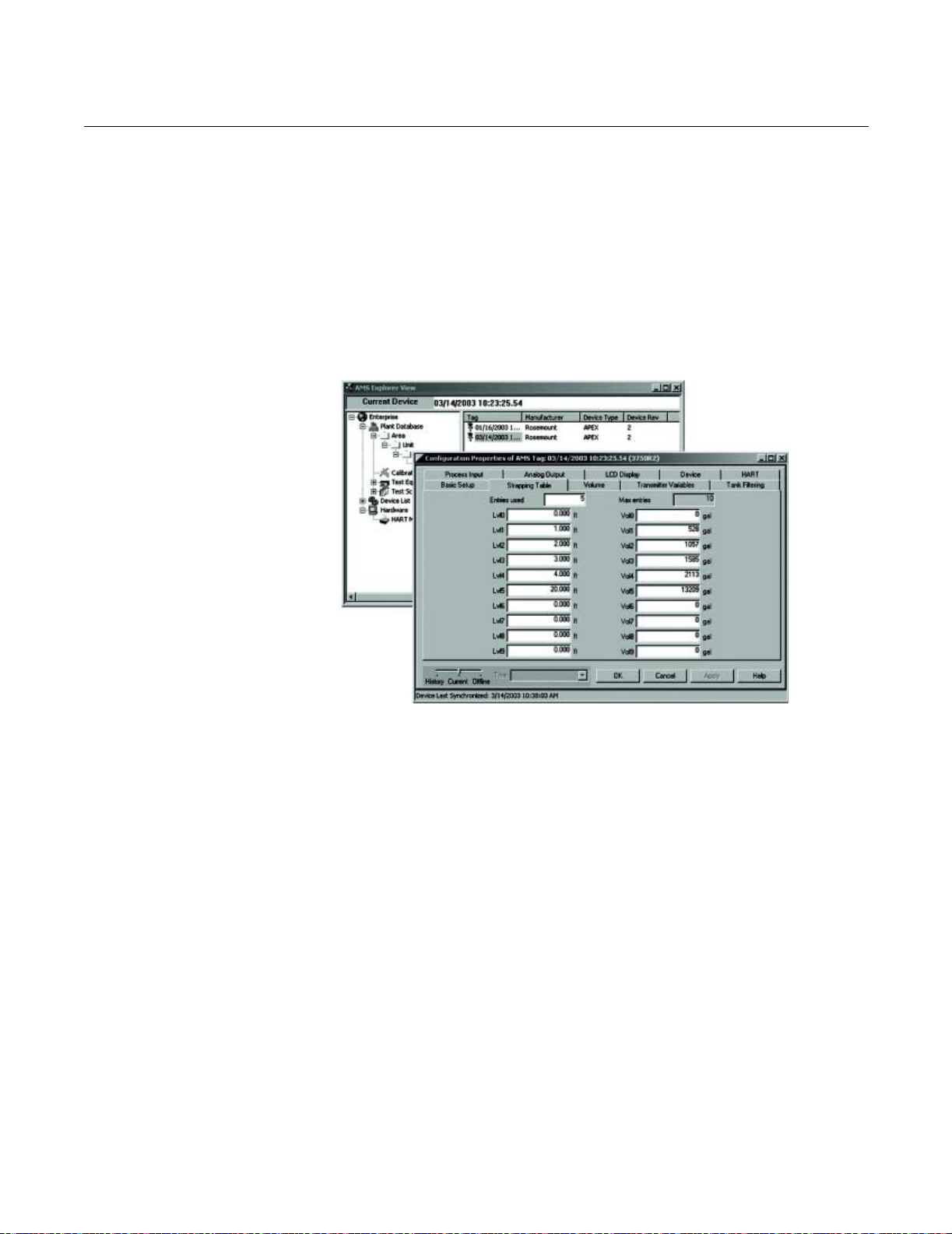
Reference Manual
00809-0100-4731, Rev FA
APEX™ and APEX Sentry™ Radar Gauge
April 2003
Strapping Table Right click on the device and select “Configuration Properties” from the menu.
Locate the Strapping Table tab and perform the following procedure:
First tell the gauge how many entries you will have; the more entries you
have, the better the gauge will be able to calculate the volume. The maximum
number of strapping points you can enter is 10.
Next, input the actual level and volume points, starting at the bottom of the
tank. It may be desirable to use most of the points in the areas of the tank that
are the least “straight.” Suggestion: Set first entry at zero level and zero
volume to enable the gauge to track volume over the entire range.
Figure 3-12. Strapping Table
Example
APEX/AMS/APEX_AMS_02A.TIF
3-22
Page 73

Reference Manual
00809-0100-4731, Rev FA
April 2003
APEX™ and APEX Sentry™ Radar Gauge
Transmitter Variables Right click on the device and select “Configuration Properties” from the menu.
Locate the Transmitter Variables tab and perform the following procedure:
1. Enter the entries in the fields provided. Click Apply.
2. An “Apply Parameter Modification” screen appears, enter desired
information and click OK.
3. After carefully reading the warning provided, select OK.
Figure 3-13. Transmitter
Variables Example
APEX/AMS/APEX_AMS_03A.TIF
3-23
Page 74

Reference Manual
00809-0100-4731, Rev FA
APEX™ and APEX Sentry™ Radar Gauge
April 2003
Rerange Right click on the device and select “Configuration Properties” from the menu.
Locate the Analog Output tab and perform the following procedure:
1. Enter the lower range value (LRV) and the upper range value (URV) in
the fields provided. Click Apply.
2. An “Apply Parameter Modification” screen appears, enter desired
information and click OK.
3. After carefully reading the warning provided, select OK.
Figure 3-14. Analog Output
Example
APEX/AMS/APEX_AMS_04A.TIF
3-24
Page 75

Reference Manual
00809-0100-4731, Rev FA
April 2003
APEX™ and APEX Sentry™ Radar Gauge
RADAR CONFIGURATION TOOL (RCT) OPTION
Installing the RCT
Software
The Radar Configuration Tool (RCT) is a user-friendly software tool that
allows you to configure the APEX Radar gauge. You can choose either of the
following two methods to configure the APEX Radar gauge:
• Start the Wizard for a guided installation if you are un-familiar with the
APEX Radar Gauge (See “Using the Setup Wizard” on page 3-27).
• Use the Setup function if you are already familiar with the configuration
process or if you want to change the current settings
(See “Using the Setup Function” on page 3-28).
To install the Rosemount Configuration Tool:
1. Insert the installation CD into your CD-Rom drive.
2. Run Setup.exe from the CD.
3. Follow the instructions.
NOTE
Do not use an alternate drive other then your hard drive when installing the
RCT Software.
To start the RCT:
1. From the Start menu click Programs > RCT Tools > RCT.
2. In the RCT Status Bar check that RCT communicates with the radar
gauge.
Figure 3-15. RCT
Communication established
Figure 3-16. RCT
Communication not established
Communication is established
(green symbol)
APEX/RCT/APEX_01AA.TIF
Communication is not established
(red symbol)
APEX/RCT/APEX_01AA.TIF
3-25
Page 76
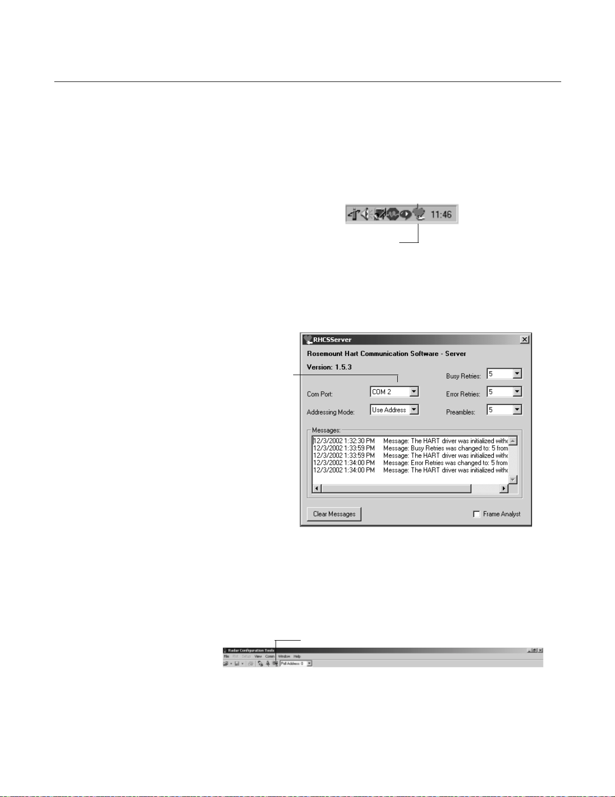
Reference Manual
00809-0100-4731, Rev FA
APEX™ and APEX Sentry™ Radar Gauge
April 2003
Specifying the COM Port If communication is not established, open the HART Communication Server
window and verify the right COM Port is selected.
To check the current COM port settings do the following:
1. Locate the HART Server icon in the lower right corner of the screen.
Figure 3-17. HART Server Icon
HART Server Icon
2. Double-click the HART Server icon.
Figure 3-18. Rosemount HART
Communication Software
APEX/RCT/10053_CA.TIF
Figure 3-19. RCT tool bar
Check that the
selected COM port
matches the
connected port on
the PC.
APEX/RCT/APEX_03AA.TIF
3. Check the COM port.
4. Choose the COM Port option that matches the COM Port connected to
the transmitter.
5. Click the Search for a device icon in the RCT tool bar:
Search for a device
3-26
PEX/RCT/APEX_04AA.TIF
Page 77

Reference Manual
00809-0100-4731, Rev FA
April 2003
APEX™ and APEX Sentry™ Radar Gauge
Using the Setup Wizard To install an APEX Radar Gauge by using the installation Wizard do the
following:
Figure 3-20. RCT workspace
Basic
Wizard
1. Start the RCT software.
2. In the RCT workspace click the Wizard icon (make sure the Basic
section is open), or choose the View > Wizard menu option.
APEX/RCT/APEX_05AA.TIF
Figure 3-21. RCT Wizard
APEX/RCT/APEX_06AA.TIF
3. Click the Start button and follow the instructions. Now you will be guided
through a number of dialogs allowing you to configure the transmitter.
3-27
Page 78

APEX™ and APEX Sentry™ Radar Gauge
Reference Manual
00809-0100-4731, Rev FA
April 2003
Using the Setup
Function
Figure 3-22. RCT workspace/
Setup Info
To install the APEX Radar Gauge by using the Setup function do the
following:
Basic
Setup
APEX/RCT/APEX_07AA.TIF
1. Start the RCT software.
2. In the RCT workspace click the Setup icon (make sure the Basic section
is open)
3. Choose the appropriate tab:
• Info: Information about the device.
• Basics: Set measurement units.
• Output: Variable assignment and range value settings.
• Tank Config: Tank height and other geometry settings, null zones, and
empty tank settings.
• Volume: Specification of tank geometry for volume calculations.
• LCD: Display panel settings.
• Advanced: Quick pick options and their required parameter settings.
3-28
Page 79

Reference Manual
00809-0100-4731, Rev FA
April 2003
Figure 3-23. Setup Info tab
APEX™ and APEX Sentry™ Radar Gauge
Setup - Info
The Info tab shows information about the connected transmitter.
Figure 3-24. Setup Basics Tab
Device Name: model designation
Device ID: 28 (Rosemount APEX Radar Gauge)
Software Rev: Software version number
APEX/RCT/APEX_08AA.TIF
Setup - Basics
The Basics tab lets you choose Measurement Units for Length, Volume, and
Temperature. These units are used wherever measurement data is
presented.
APEX/RCT/APEX_09AA.TIF
This window also allows you to enter some general information about the
transmitter like Message, Tag, Descriptor, and Date. This information is not
required for the operation of the transmitter and can be left out if desired.
3-29
Page 80

APEX™ and APEX Sentry™ Radar Gauge
Setup- Output
The Output tab lets you assign up to four transmitter variables.
Figure 3-25. Setup Output Tab
Reference Manual
00809-0100-4731, Rev FA
April 2003
APEX/RCT/APEX_10AA.TIF
Typically, the Primary Variable (PV) is configured to be Product Level,
Interface Level, or Volume.
Set the Lower Range Value (4 mA) and the Upper Range Value (20 mA) to
the desired values. Keep in mind the 20 mA value should be below the Upper
Null Zone.
RTD Usage should be checked if an RTD is used with the gauge.
3-30
Page 81

APEX™ and APEX Sentry™ Radar Gauge
Setup - Tank Config
The Tank Configuration tab contains information on tank geometry.
Figure 3-26. Setup Tank
Configuration Tab
Reference Manual
00809-0100-4731, Rev FA
April 2003
APEX/RCT/APEX_11AA.TIF
Tank Geometry
The Gauge Height (RGH) is the distance from the Upper Reference Point
to the bottom of the tank. When setting the Reference Gauge Height, keep
in mind that this value is used for all measurements performed by the
APEX Radar Gauge. The Gauge Height must be set in linear (level) units,
such as feet or meters, regardless of primary variable assignment.
The Upper Null Zone (UNZ) should not be changed unless there are
disturbances at the top of the tank. By increasing the Upper Null Zone
value measurements in this region can be avoided. The UNZ is equal to
19.6 inches (0.5 m) in the factory configuration.
NOTE
The gauge cannot reliably read measurements too close to the antenna.
The Lower Null Zone (LNZ) should not be changed unless there are
disturbances at the bottom of the tank. By increasing the Lower Null Zone
value measurements in this region can be avoided. The LNZ is equal to
-19.6 inches (-0.5 m) in the factory configuration.
3-31
Page 82
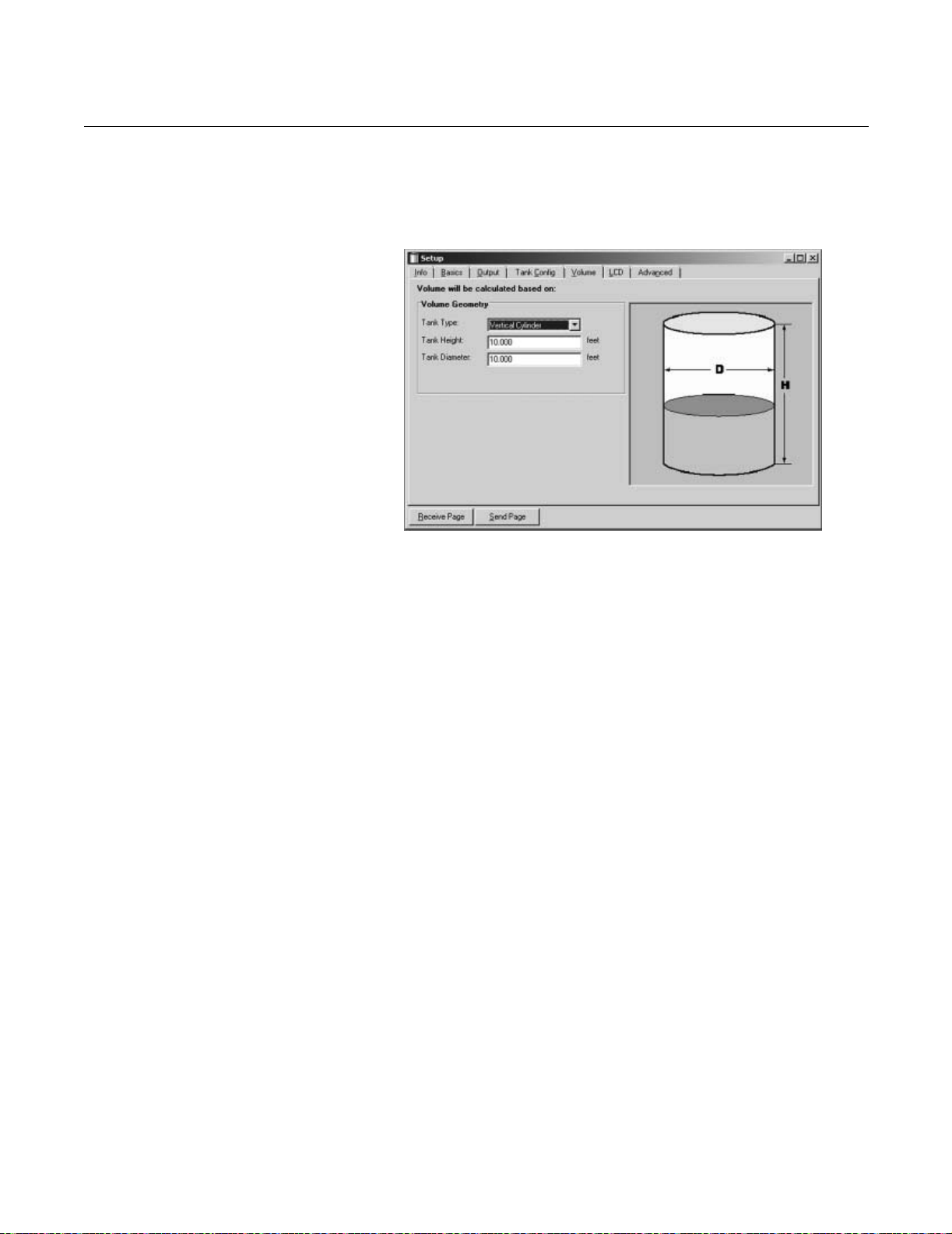
APEX™ and APEX Sentry™ Radar Gauge
Setup - Volume
The Volume tab lets you configure the transmitter for volume calculations.
Figure 3-27. Setup Tank Volume
Ta b
Reference Manual
00809-0100-4731, Rev FA
April 2003
You can choose one of the standard tank shapes or the strapping option.
Choose None if volume calculation is not used at all.
Choose one of the following options:
• None
• Strap Table
• Vertical Cylinder
• Horizontal Cylinder
• Vertical Bullet
• Horizontal Bullet
• Sphere
APEX/RCT/APEX_12BA.TIF
3-32
Page 83

APEX™ and APEX Sentry™ Radar Gauge
Setup - LCD
The LCD tab lets you specify which parameters to appear on the display
panel.
Figure 3-28. Setup Tank LCD
Ta b
Reference Manual
00809-0100-4731, Rev FA
April 2003
Choose one the following options:
Parameter Description
Level Product Level
Distance Distance from upper reference point to product surface
Volume Total product volume
Internal Temperature Temperature inside the transmitter housing
RTD Temperature Temperature report from connected RTD (optional)
RTD Ohms Resistance report from connected RTD (optional)
Standard Volume Product volume corrected for temperature
Loop Voltage Voltage of loop at device terminal
DSP Signal/ Noise An indicator of signal quality
DSP Target Strength An indicator of signal quality
LNF Counter A counter indicating lost targets (typically 0)
LF Counter A counter indicating found targets (typically 8)
Percent Range Level value in percent of total measurement range
APEX/RCT/APEX_13AA.TIF
3-33
Page 84

APEX™ and APEX Sentry™ Radar Gauge
Setup - Advanced
The Advanced tab lets you specify which quick pick option and required
parameters to configure.
Figure 3-29. Setup Tank
Advanced Tab
Reference Manual
00809-0100-4731, Rev FA
April 2003
Figure 3-30. Quick Pick Option Empty Tank
APEX/RCT/APEX_14AA.TIF
• Empty Tank - turns on when level is below the empty tank setting.
The Empty Tank option controls gauge function when target is lost after
level drops below the empty tank setting. This is typically used in
non-flat bottom vessels. It prevents the gauge from going into full
search mode when a vessel is empty. The gauge will focus its search in
the area below the Empty Tank setting and wait for vessel filling to
begin.
APEX/RCT/APEX_23AA.TIF
3-34
Page 85
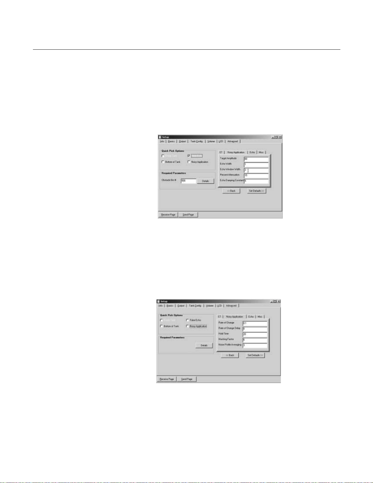
APEX™ and APEX Sentry™ Radar Gauge
• False Echoes - minimizes reflection from a false target that is within
the measurement range. Use this when the gauge occasionally locks
on a false target when the level drops below it.
To use this function, the false target must be identified by its bin
number. To learn this, run a tank plot and spectrum (under the
Advanced Tab) and locate the false target and associated bin number.
Input this value as shown in Figure 3-31. Consult the factory for
assistance.
Figure 3-31. Quick Pick Option False Echo
Reference Manual
00809-0100-4731, Rev FA
April 2003
Figure 3-32. Quick Pick Option Noisy Applications
APEX/RCT/APEX_22AA.TIF
• Bottom of Tank - allows the gauge to track just beyond the LNZ
without alarming. This option prevents the gauge from locking onto the
tank bottom. The Bottom of Tank tab is often used in flat bottom tanks
with low dielectric fluids.
• Noisy Applications - includes applications with high turbulence or
occasional foam where the level target will disappear for short periods
of time. This option increases the amount of time that gauge will look
for a target within the tracking window before alarming.
APEX/RCT/APEX_20AA.TIF
3-35
Page 86

APEX™ and APEX Sentry™ Radar Gauge
• Miscellaneous - allows you to change the target window size and the
tracking window size.
Figure 3-33. Quick Pick Option Miscellaneous
Logging Measurement Data
To start logging do the following:
Reference Manual
00809-0100-4731, Rev FA
April 2003
APEX/RCT/APEX_21AA.TIF
1. Click the Monitor icon in the RCT workspace or choose the Monitor
option for the View menu.
Basic
Monitor
2. Choose the desired variables to be monitored. Click the Start Monitoring
button.
APEX/RCT/APEX_26AB.TIF
3-36
Page 87

APEX™ and APEX Sentry™ Radar Gauge
Start Monitoring
Start Disk Logging
Saving the log to a disk
00809-0100-4731, Rev FA
Log Interval
Reference Manual
April 2003
Counter
APEX/RCT/APEX_26AA.TIF
1. Choose the desired variables to be monitored.
2. Click the Log interval button and enter a time interval. For example, type
10 if you want data to be logged every tenth of a second.
3. Click the Counter button and enter the maximum number of files to be
stored. The Counter is used to limit the amount of data stored on the
hard disk. Each time the maximum number of entries in a log file is
reached, the current log file is saved and a new file is created. This
procedure continues up to the maximum number of files given by the
Counter value. The file size is limited to 60000 entries which can easily
be handled by spreadsheet programs such as MS Excel.
4. Select the desired options of Timer, Time, and Date. By selecting a
check box the corresponding time indication is stored for each log entry
in the log file.
5. Click the Start disk logging button.
6. Choose a destination folder and enter a file name.
3-37
Page 88

APEX™ and APEX Sentry™ Radar Gauge
Using the Advanced Tab Tank Plotting
Advanced
Tan k
Plotting
Reference Manual
00809-0100-4731, Rev FA
April 2003
APEX/RCT/APEX_24AA.TIF
Memory Map
A recording of all the memory files and a listing of standard defaults.
Advanced
Memory Map
APEX/RCT/APEX_27AA.TIF
3-38
Page 89

Reference Manual
00809-0100-4731, Rev FA
April 2003
APEX™ and APEX Sentry™ Radar Gauge
Section 4 Hardware and Software
Maintenance and
Troubleshooting
Safety Messages . . . . . . . . . . . . . . . . . . . . . . . . . . . . . . . . . page 4-1
Preventive Maintenance . . . . . . . . . . . . . . . . . . . . . . . . . . . page 4-2
Alarm and Diagnostic Messages . . . . . . . . . . . . . . . . . . . . page 4-3
Local Operator Interface Display . . . . . . . . . . . . . . . . . . . page 4-7
HART Communicator Software Diagnostics . . . . . . . . . . page 4-7
AMS Configuration Software Diagnostics . . . . . . . . . . . . page 4-8
Removing the Gauge Housing From the Flange . . . . . . . page 4-10
This section provides information on preventive maintenance and diagnostic
and alarm messages displayed by the APEX and APEX Sentry Radar
Gauges and the HART Communicator.
SAFETY MESSAGES NOTE
All information included refers to both the APEX Radar Gauge and the APEX
Sentry Radar Gauge unless otherwise stated.
Procedures and instructions in this section may require special precautions to
ensure the safety of the personnel performing the operations. Information that
raises potential safety issues is indicated by a warning symbol ( ). Please
refer to the following safety messages before performing an operation
preceded by this symbol.
Explosions could result in death or serious injury:
Failure to follow safe installation and servicing guidelines could result in death or
serious injury:
• Verify that the operating environment of the gauge is consistent with the
appropriate hazardous locations certifications.
• Before connecting a HART-based communicator in an explosive atmosphere,
make sure the instruments in the loop are installed in accordance with intrinsically
safe or non-incendive field wiring practices.
• Do not remove the gauge cover in explosive atmospheres when the circuit
is alive.
• Make sure only qualified personnel perform these procedures.
• Use the equipment only as specified in this manual. Failure to do so may impair
the protection provided by the equipment.
• Do not perform any service other than those contained in this manual unless you
are qualified.
www.rosemount.com
Page 90

APEX™ and APEX Sentry™ Radar Gauge
High voltage that may be present on leads could cause electrical shock:
• Avoid contact with leads and terminals.
• Make sure the main power to the APEX Radar Gauge is off and the lines to any
other external power source are disconnected or not powered while wiring the
gauge.
As a matter of routine, shut off the APEX Radar Gauge and all other equipment in the
tank before you enter the tank.
People who handle products exposed to a hazardous substance can avoid injury if they are
informed and understand the hazard.
Return of Materials: If the product being returned was exposed to a hazardous substance
as defined by OSHA, a copy of the required Material Safety Data Sheet (MSDS) for each
hazardous substance identified must be included with the
returned products.
Reference Manual
00809-0100-4731, Rev FA
April 2003
PREVENTIVE MAINTENANCE
The APEX and APEX Sentry Radar Gauges have built-in diagnostics and
self-tests that generate alarms if certain failures occur. In addition, there are a
few basic things you may want to check periodically to prevent problems
from occurring.
Use only the procedures and new parts specifically referenced in this manual
to ensure specification performance and certification compliance.
Unauthorized procedures or parts may affect product performance and the
output signal used to control a process.
Product Buildup If you have a process that produces condensate or is prone to coating, check
the radar antenna for product buildup. If buildup appears on the inside or
outside of the antenna, clean it with a solvent that will not damage the SST
antenna material, flange, or PTFE/ceramic waveguide.
Splashing and Coating
• Horn antennas can be recessed into the nozzle to protect against
coating.
- Gas purge can be used
- Intermittent water purge can be used.
• In other cases, periodic cleaning might be required.
Flushing Connection
A flushing connection (Figure 4-1) may be installed to prevent corrosion on
the radar antenna.
Refer to “Safety Messages” on page 4-1 and for more information.
4-2
Page 91
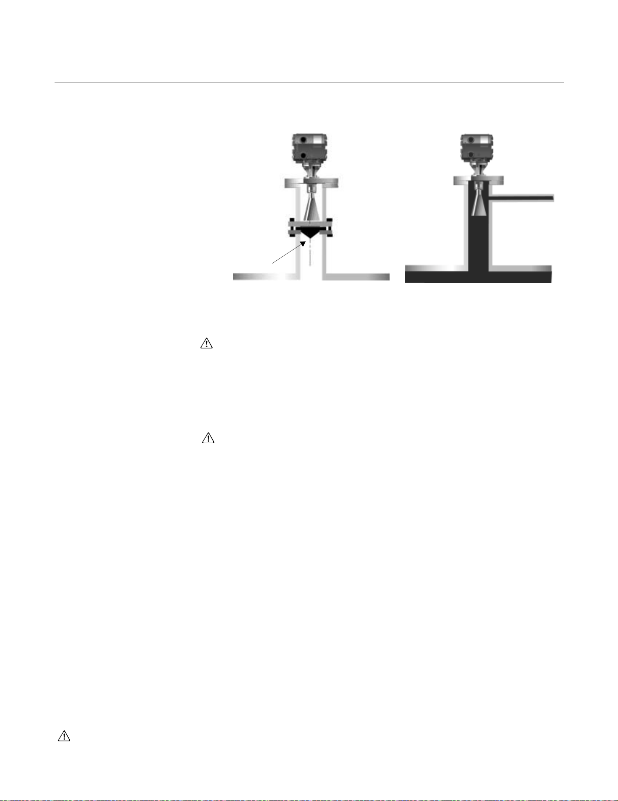
Reference Manual
00809-0100-4731, Rev FA
April 2003
Figure 4-1. APEX Radar Gauge
with flushing connection
APEX™ and APEX Sentry™ Radar Gauge
Flushing Connection with Window
Window
Flushing Connection with No Window
Performance Check the level output from the radar gauge by comparing the gauge output
with a hand dip or other means that is suitable for a level comparison.
LEVEL/APEX NEW/GASPURGE_FA; GASPURGE_CA
ALARM AND DIAGNOSTIC MESSAGES
Check the 4–20 mA output with a milliampere meter or read the signal on a
current indicator. You can do this type of test by performing a loop test using
the HART Communicator. Before connecting a HART-based communicator in
an explosive atmosphere, make sure the instruments in the loop are installed
in accordance with intrinsically safe or non-incendive field wiring practices.
Set the 4–20 mA current to 4 mA and measure or display the signal on the mA
meter or indicator. Check the 20 mA in the same manner.
Check the ac or dc power supply that supplies operating power to the gauge
to make certain it is still operating within specifications. If a separate dc power
supply is used for the 4–20 mA output, check the dc power supply to make
certain it is still operating within its specifications. Avoid contact with leads
and terminals.
Table 4-1 is a list of alarm and diagnostic messages that may be displayed on
the Integral Display (if installed) or on the Model 275 HART Communicator.
Some of the messages involve the digital signal processor (DSP), which is
one of the microprocessor boards. It simply indicates that this board
originated the message. Also, you will see “Radar Configuration Tools (RCT)”
mentioned in the “Action” column of the table.
If any of these problems persist after performing the suggested action, contact
Rosemount Customer Central at 1-800-999-9307.
If you encounter any of these messages immediately after start up, wait 30
seconds to allow the gauge to “lock on” to a signal. If, after 30 seconds, these
messages are still displayed, follow the course of action listed below.
Refer to “Safety Messages” on page 4-1 and for more information.
4-3
Page 92

Reference Manual
00809-0100-4731, Rev FA
April 2003
Table 4-1. Alarm and Diagnostic Messages
Displayed Message Cause Action
dspNotResponding The DSP is not responding to a request to
dspOutOfLimits One of three conditions could cause this
dspReportsError The DSP has set one of its 32 error flags. If other messages are present, follow
dspReportWarning The DSP has set one of its 32 warning flags. If other messages are present, follow
DSP Startup in Progress
or
DSP Error #6
DSP EEPROM failure
or
DSP Error #14
eepromFactAreaFailure Part of the EEPROM can be configured only at
eepromUserChecks
or
eepromUserAreaFailure
Factory Alg Param Invalid
or
DSP Warning #26
High Signal Strength
or
Warning: Signal
too strong
or
DSP Warning #0
Incorrect Alg Lib Vers
or
DSP Error #25
APEX™ and APEX Sentry™ Radar Gauge
return the distance.
message:
Level is returned as “Not a Number” (usually
resulting from a “dspNotResponding”
condition).
Level is less than the lower null zone.
Level is greater than (Reference Gauge
Height – upper null zone).
Advisory No action necessary; gauge is starting up.
Electronics Failure Call Rosemount Customer Central. The unit will
the factory. The checksum for this portion of
the EEPROM does not match the contents.
Part of the EEPROM can be configured by the
user, normally using a 275 or RCT. The
checksum for this portion of the EEPROM
does not match the contents.
Configuration Warning Verify 4-20 mA Settings, null zone configurations,
Process Condition: Return signal is stronger
than expected.
The radar gauge is either too close to the
product or there is a failure in the gauge.
or
The radar gauge is in a stilling well.
Internal Software Error Call Rosemount Customer Central. The unit will
Verify that the gauge is getting enough power.
See page A-7 for power requirements
Verify that the APEX gauge is properly installed;
the target (product) must be within 98 ft (30 m) of
the flange but no closer than 19.6 in. (0.5 m).
Cycle power or use a Model 275, AMS, or RCT to
reset.
This message most frequently appears during
start-up; wait 30 seconds and if the message
persists, follow steps 2 and 3.
Verify that the Reference Gauge Height and null
zones are set correctly.
Check the Reference Gauge Height first because
setting the Reference Gauge Height will cause
the lower null zone to reset to its default value.
recommended action(s) for those messages;
verify configuration.
Cycle power or use a 275 or RCT to reset.
recommended action(s) for those messages.
Some warnings, especially #5, may appear for a
few seconds when the APEX gauge is being
configured. If it persists, verify configuration.
Cycle power or use a 275 or RCT to reset.
most likely need advanced troubleshooting in the
field or will need to be returned to the factory for
repair.
Call Rosemount Customer Central for
further assistance.
Use a 275 or RCT to change some portion of the
user EEPROM. (For example, change the
message tag, descriptor, or date.) This causes
the checksum to be updated.
Verify 4-20 mA Settings, null zone configurations,
Reference Gauge Height, empty tank detection
zone, etc.
Cycle power or use a 275 or RCT to reset.
Reference Gauge Height, empty tank detection
zone, etc.
If error persists, call Rosemount
Customer Central.
The product is too close to the gauge, the nozzle
is obstructed, or there is a failure in the gauge. If
the message persists throughout the
measurement range, the beam is unobstructed,
and the level measurement is not correct, the
gauge has failed. Call Rosemount Customer
Central to arrange a return.
most likely need to be sent in for repair.
4-4
Page 93

Reference Manual
00809-0100-4731, Rev FA
April 2003
Table 4-1. Alarm and Diagnostic Messages
Displayed Message Cause Action
intTempOutOfRang
or
Internal PRT out of range
invalidConfigur A background task that validates the APEX
Invalid DSP Command
or
DSP Error #26
INVALID TEST CMD PARAM
or
DSP Warning #27
DSP Error #5 Electronics Failure: Inadequate signal strength
lowTermVoltage The power supply for the HART
Low Signal Strength
or
DSP Warning #1
ramFailure Write/read tests of RAM failed. Cycle power or use a 275 or RCT to reset.
romChecksum
or
romChecksumFailure
rtdOutOfLimits
or
RTD out of sensor limits
softwareError A stack overflow occurred in the transmitter. Cycle power or use a 275 or RCT to reset.
Target in null zone
or
DSP Warning #5
Targ et l ost o r
Error: lost signal
or
DSP Error #7
APEX™ and APEX Sentry™ Radar Gauge
The APEX gauge internal temperature
appears to be less than –40 °F (–40 °C) or
greater than 185 °F (85 °C).
gauge configuration has found one or more
discrepancies.
This flag is also set if certain key items (polling
address, LCD language, dynamic variable
assignments, sample time) must be reset to
reasonable values at start-up.
Internal Software Error Call Rosemount Customer Central. The unit will
Configuration Warning Verify 4-20 mA settings, null zone configurations,
returning to gauge.
communications loop has dropped below 5 V;
current will be fixed at 1 mA.
Inadequate Return Signal Check nozzle for obstructions/debris that could
The checksum for the ROM code does not
match the contents.
RTD is missing, wired incorrectly, or returning
invalid data.
Process Condition: Target has moved into a
null zone
Configuration or Process Error: APEX cannot
find a target in the tank.
Take appropriate measures to ensure that the
housing remains within the specified temperature
limits. See Appendix A: Reference Data.
Cycle power or use a 275 or RCT to reset.
Verify configuration after Master Reset; verify
4-20 mA settings, null zone configurations,
Reference Gauge Height, empty tank detection
zone, etc.
most likely need to be sent in for repair.
Reference Gauge Height, empty tank detection
zone, etc.
If error persists, call Rosemount
Customer Central.
Cycle power or use a Model 275, AMS,
or RCT to reset. If error does not
clear, call Rosemount Customer Central for
additional troubleshooting. Unit may
need repair.
Provide a proper power supply for HART
communications (10.5 - 55 vdc).
weaken the signal
May occur in applications with occasional foam or
in presence of low dielectric and heavy
turbulence.
Cycle power or use a 275 or RCT to reset.
If no RTD should be present, use a 275 or RCT to
disable the RTD.
Otherwise, verify that the RTD is wired and
working correctly.
Verify that null zones are configured correctly for
your tank. (This message will only display for
about one minute; the gauge will start to ignore
the signal after that).
Null zones may need to be adjusted;
see page 3-11. After adjustment, Cycle Power or
use a Model 275, AMS, or RCT to reset. This will
reset the alarm condition.
Verify that the unit is configured correctly and that
the beam has a clear shot to the target.
4-5
Page 94

Reference Manual
00809-0100-4731, Rev FA
April 2003
Table 4-1. Alarm and Diagnostic Messages
Displayed Message Cause Action
Empty tank
or
DSP Warning #7
or
Warning: Empty Tank
or
Empty Tank
mode Active
User Alg Param invalid
or
USR ALG PAR OUT OF RNG
or
DSP Warning #25
VCO Cal Failure #X
or
DSP Error #16, 17, 22, or 31
VCO Calibration Retry
or
DSP Warning #18
volumeInputError The level from which the volume would be
DSP EEPROM failure
or
DSP Error #14
DSP Error #3
or
DSP Error #4
VCO Cal Failure #27 or 28
or
DSP Error #27 or 28
VCO Cal Failure #18 or 19
or
DSP Error #18 or 19
DSP Error #9 or 10 Electronics Failure Cycle power; if error does not clear in a few
DSP Warning #19 Software Error Cycle power; if error does not clear, call
APEX™ and APEX Sentry™ Radar Gauge
Process Condition: Target has moved into the
empty tank detection zone, and the signal has
been lost.
Configuration Warning: User entered
parameter does not fit within suggested
guidelines.
Electronics Failure Note failure number (#), and call Rosemount
Internal Software Warning: This message will
either go away in several seconds to be
replaced by another or the unit will fail.
computed is beyond the physical dimensions
of the tank (one or more of the following):
The level is less than zero.
For a sphere or horizontal tank, the level is
greater than twice the radius.
For an upright tank, the level is greater than
the height of the tank.
If a strapping table is being used, an invalid
number of strapping points has been defined
(fewer than 2 or more than 10).
Electronics Failure If error does not clear after power is cycled, call
Hardware Failure Cycle power; if the error does not clear, the
Electronics Failure Cycle power; if the message does not clear within
Electronics Failure Cycle power; if the error is followed by other
Is the tank empty? If so, the gauge is operating
correctly; if not, reconfigure the empty tank
detection zone (see page 3-6).
Verify 4–20 mA settings, null zone configurations,
Reference Gauge Height, empty tank detection
zone, etc.
If error persists, call Rosemount Customer
Central for further guidance.
Customer Central. The unit will most likely need
to be sent in for repair.
Cycle power; if the message does not disappear
within 30 seconds, the unit has failed; call
Rosemount Customer Central to arrange for
repair.
If no strapping table is being used, verify that the
tank type, height, and width have been entered
correctly.
If a strapping table is being used, verify
the following:
Tank type = strapping table.
Number of strapping table entries ≥ 2 and ≤ 10).
All strapping entries are in ascending order.
Any level to be measured is within the range of
the strapping table entries.
Rosemount Customer Central for further
troubleshooting. The gauge may require service
in the field.
gauge will need to be sent in for repair.
three minutes, the gauge will need to be returned
or serviced in the field.
errors, follow instructions listed for those errors. If
the error does not clear in five minutes, it will
need to be returned to the factory for repair.
minutes, the gauge will need to be repaired.
Rosemount Customer Central
4-6
Page 95

Reference Manual
00809-0100-4731, Rev FA
April 2003
Table 4-1. Alarm and Diagnostic Messages
Displayed Message Cause Action
DSP Warning #20 Advisory The error will either clear in a few minutes or be
DSP Warning #9 Hardware Warning This is probably an informational warning. If this
**If you get an error message that is not listed here, it was not in use at this printing.
Call Rosemount Customer Central (1-800-999-9307) for guidance.
APEX™ and APEX Sentry™ Radar Gauge
accompanied by another error.
message is not accompanied by any other
messages, and the gauge seems to be
functioning properly, this message can be
ignored. If, however, it is accompanied by any
other warnings, refer to these warnings.
LOCAL OPERATOR INTERFACE DISPLAY
HART COMMUNICATOR SOFTWARE DIAGNOSTICS
If the red light is blinking constantly, it could be due to dirt over one of the
optical switches. Try to clean the outside of the Local Operator Interface glass
to see if the blinking stops.
When using the HART Communicator to communicate with the APEX and
APEX Sentry Radar Gauges, you may encounter software diagnostic
messages. These messages may indicate problems with the equipment or
mistakes made in entering data, while others act as reminders to you.
Before connecting a HART-based communicator in an explosive atmosphere,
make sure the instruments in the loop are installed in accordance with
intrinsically safe or non-incendive field wiring practices.
Section 3: Configuration describes some of the messages displayed by the
HART Communicator, generally explains why they occur, and provides
instructions for responding to each message.
4-7
Page 96

Reference Manual
00809-0100-4731, Rev FA
April 2003
APEX™ and APEX Sentry™ Radar Gauge
AMS CONFIGURATION SOFTWARE DIAGNOSTICS
When using AMS to communicate with the APEX and APEX Sentry Radar
Gauges, you may encounter software diagnostic messages. These messages
may indicate problems with the equipment or mistakes made in entering data,
while others act as reminders to you.
The following shows some of the error messages displayed by the AMS
software.
APEX/AMS/APEX_AMS_05A.TIFAPEX/AMS/APEX_AMS_07A.TIF
4-8
Page 97
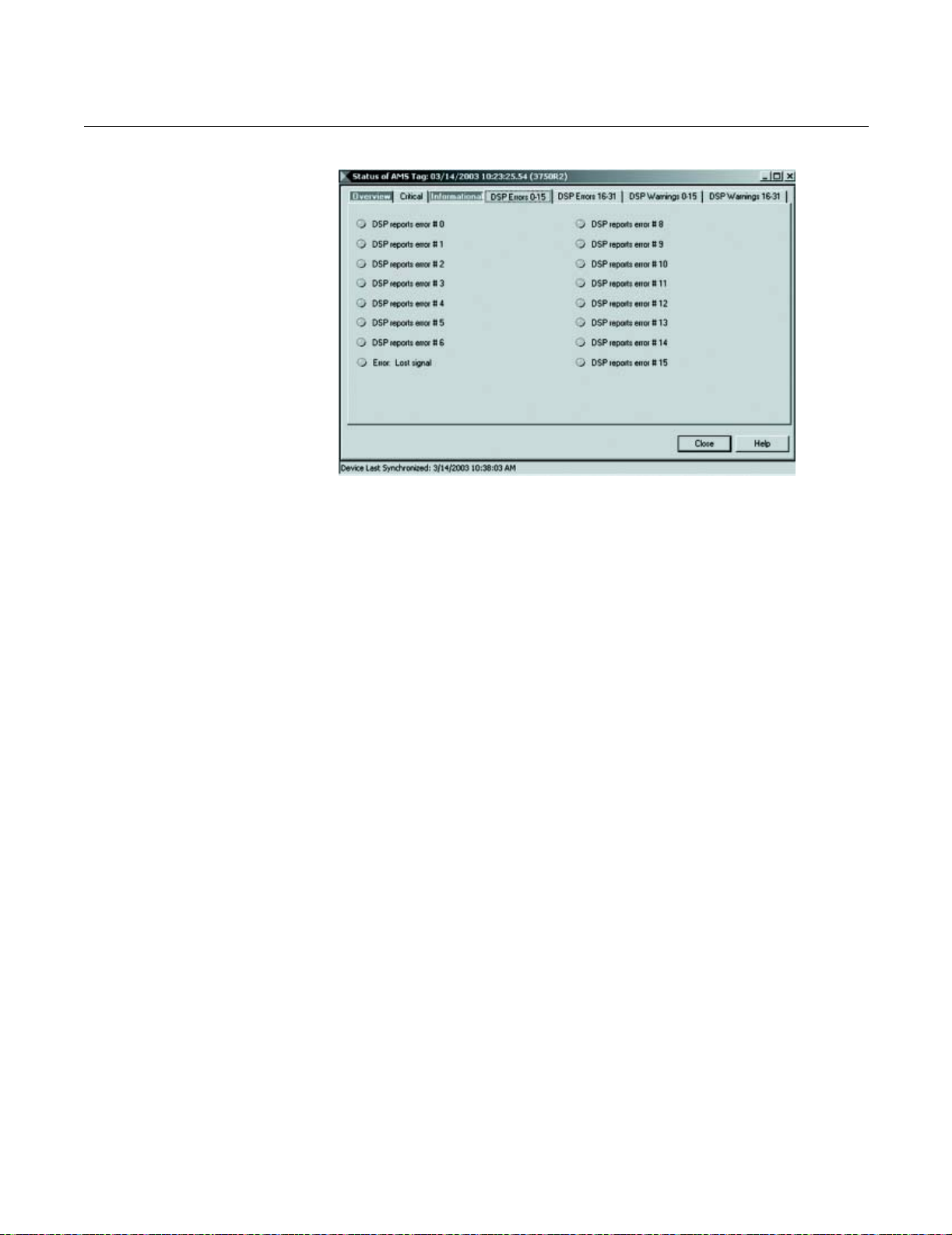
Reference Manual
00809-0100-4731, Rev FA
April 2003
APEX™ and APEX Sentry™ Radar Gauge
APEX/AMS/APEX_AMS_06A.TIF
4-9
Page 98

Reference Manual
00809-0100-4731, Rev FA
April 2003
APEX™ and APEX Sentry™ Radar Gauge
REMOVING THE GAUGE HOUSING FROM THE FLANGE
Figure 4-2. Removing the gauge
housing from the flange
If rigid conduit is used, first remove the conduit from the gauge. If you have
been instructed by a Rosemount representative to remove the gauge housing
from the flange, without breaking the process seal, remove the four ¼–28
UNF–2A bolts at the base of the housing adapter (Figure 4-2). Use the
equipment only as specified in this manual. Failure to do so may impair the
protection provided by the equipment.
NOTE
If the electronics housing needs to be rotated, do not un-bolt the
adapter-to-housing bolts! Un-bolt the flange bolts and rotate as needed. If
the housing is rotated at the housing-to-adapter connection, the gauge will be
irreparably damaged, and the warranty will be invalidated. Do not remove or
handle the electronic components.
Housing
Adapter
Adapter to
Flange Bolts
Flange
DO NOT UN-BOLT HERE
Un-bolt flange bolts to rotate
4-10
LEVEL-0021B
Page 99

Reference Manual
00809-0100-4731, Rev FA
April 2003
APEX™ and APEX Sentry™ Radar Gauge
Appendix A Reference Data
Antenna Selection Guidelines . . . . . . . . . . . . . . . . . . . . . . page A-1
Telecom Restrictions . . . . . . . . . . . . . . . . . . . . . . . . . . . . . page A-2
Equipment Description . . . . . . . . . . . . . . . . . . . . . . . . . . . page A-4
Performance Specifications . . . . . . . . . . . . . . . . . . . . . . . page A-4
Environmental Conditions . . . . . . . . . . . . . . . . . . . . . . . . . page A-5
Electrical Specifications . . . . . . . . . . . . . . . . . . . . . . . . . . page A-5
Calibration . . . . . . . . . . . . . . . . . . . . . . . . . . . . . . . . . . . . . . page A-7
Software Functionality . . . . . . . . . . . . . . . . . . . . . . . . . . . .page A-7
Weight . . . . . . . . . . . . . . . . . . . . . . . . . . . . . . . . . . . . . . . . . page A-7
Materials of Construction . . . . . . . . . . . . . . . . . . . . . . . . . page A-8
Dimensional Drawings . . . . . . . . . . . . . . . . . . . . . . . . . . . .page A-9
Ordering Information . . . . . . . . . . . . . . . . . . . . . . . . . . . . . page A-12
ANTENNA SELECTION GUIDELINES
Selecting an antenna size can be as simple as matching the available
process opening to the antenna size. However, when selecting an antenna,
consider the following:
• A larger antenna will yield the strongest, most concentrated signal.
Fluids with low dielectric constants, such as many hydrocarbons and
solvents, only reflect a small portion of the radar signal. A more
focused beam that is provided by a larger antenna will yield a stronger
signal. This is especially important as the distance to the fluid
surface increases.
• Ideally, the beam should not be obstructed by the sides of the vessel or
any other equipment in the tank. Consult the beamwidth table to
determine the size of the beam at its maximum expected distance
(lowest tank level). Since beamwidth decreases as the antenna size
increases, the beam from a larger antenna is least likely to encounter
obstructions.
• In stilling wells and bypass assemblies, the pipe will prevent dispersion
of the beam and will yield a very concentrated signal. In those
situations, a smaller antenna is suitable. The use of stilling wells may
impact the accuracy.
• In general, 3-in. and 4-in. antennas can be used in nozzles that have
an unobstructed total length of up to 1 m (39 in.). It is recommended
that 2-in. antennas be used only in nozzles where the total length is
less than 0.35 m (14 in.). Consult the factory for assistance with
exceptions.
www.rosemount.com
Page 100

Reference Manual
00809-0100-4731, Rev FA
APEX™ and APEX Sentry™ Radar Gauge
April 2003
TELECOM RESTRICTIONS
Country Installation Restrictions Other Comments
Argentina Metal tanks Average field intensity: <500µW/m at 3 meters.
Austria General approval
Australia Shielded tanks 24.05-26.05 GHz, 75 nW eirp
Belgium Metal tanks
Bolivia Metal tanks No license required if installed in metal tank
Brazil Metal tanks 24.05-26.05 GHz Emission designation 2G00N0N, RF 46mW
Canada Metal tanks 24.05-26.05 GHz, emission designation 2G00N0N, 46mW
Chad Nothing required, no approval agency
Chile Metal tanks 24.05-26.05 GHz Average Field Intensity: <500 µW/m at 3 meters
China 24.05-26.05 GHz, transmitting power <10mW, spurious emissions <-30dBm
Colombia
Costa Rica Metal tanks Transmitting power <10mW
Croatia Standard EN55022
Czech Republic Metal tanks
Denmark Metal tanks EN55022
Ecuador
Egypt
Eire/Ireland Metal tanks
Finland Metal tanks
France
Germany Metal tanks
Hong Kong
Hungary Metal tanks
India 24.05-26.05 GHz, 2G00N0N, <10mW
Indonesia
Italy Metal tanks Electromagnetically screened environment
Jamaica Metal tanks Average field intensity: <500 µW/m at 3 meters.
Japan
Jordan Nothing required, no approval agency
Korea
Kuwait Metal tanks
Malaysia “In-house” and “in-building”
installation required
Mexico
Netherlands Metal tanks Manual must state that use is restricted to closed or vented metal tanks
New Zealand Metal or radio frequency
shielded tanks
Nicaragua Metal tanks
Norway Metal tanks 24.04-26.05 GHz
Oman Letter of no objection - “each application for use will have to be studied and if
Peru
Philippines
Poland Metal tanks Sit approval required for installations other than in metal tanks
Portugal Metal tanks 24.05-26.05 GHz, 2.7 W eirp
Puerto Rico
Romania
Russia
Saudi Arabia No government approval needed
Singapore Metal tanks 24.05-26.05 GHz, average field strength <500 µW/m at 3 meters, FMCW
Peak field intensity <5000 µW/m at 3 meters
(1)
Followed FCC
May only be used on a non-interference radio basis, broadcasting <50mW
<75nW eirp
allowed earn our approval and permission to import”
(1)
(1)
, 2G00N0N
A-2
 Loading...