

Page 1

Instruction Manual
748441-D
May 2004
Model CAT 100
Continuous Analyzer Transmitter
http://www.processanalytic.com
Page 2

ESSENTIAL INSTRUCTIONS
READ THIS PAGE BEFORE PROCEEDING!
Rosemount Analytical designs, manufactures and tests its products to meet many national and international standards. Because these instruments are sophisticated technical products, you
MUST properly install, use, and maintain them
normal specifications. The following instructions MUST be adhered to
safety program when installing, using, and maintaining Rosemount Analytical products. Failure to
follow the proper instructions may cause any one of the following situations to occur: Loss of life;
personal injury; property damage; damage to this instrument; and warranty invalidation.
to ensure they continue to operate within their
and integrated into your
• Read all instructions
prior to installing, operating, and servicing the product.
• If you do not understand any of the instructions, contact your Rosemount Analytical repre-
sentative for clarification.
•
Follow all warnings, cautions, and instructions
•
Inform and educate your personnel in the proper installation, operation, and mainte-
marked on and supplied with the product.
nance of the product.
•
Install your equipment as specified in the Installation Instructions of the appropriate Instruction Manual and per applicable local and national codes. Connect all products to the
proper electrical and pressure sources.
•
To ensure proper performance, use qualified personnel
to install, operate, update, program,
and maintain the product.
• When replacement parts are required, ensure that qualified people use replacement parts
specified by Rosemount. Unauthorized parts and procedures can affect the product’s performance, place the safe operation of your process at risk, and VOID YOUR WARRANTY
.
Look-alike substitutions may result in fire, electrical hazards, or improper operation.
•
Ensure that all equipment doors are closed and protective covers are in place, except
when maintenance is being performed by qualified persons, to prevent electrical shock
and personal injury.
The information contained in this document is subject to change without notice.
Teflon® and Viton® are registered trademarks of E. I. duPont de Nemours and Co., Inc.
SNOOP® is a registered trademark of NUPRO Co.
st
1
Edition 04/2002 2nd Edition: 05/2004
Emerson Process Management
Manufacturing GmbH & Co. OHG
Industriestrasse 1
D-63594 Hasselroth
T +49(6055) 884-0
F +49(6055) 884-209
http://www.emersonprocess.com
Page 3

Model CAT 100
PREFACE...................................................... .............................................. .......................................P-1
Definitions............................................................................. ..............................................................P-1
Intended Use Statement.....................................................................................................................P-2
Safety Summary.................................................................................................................................P-2
General Precautions For Handling And Storing High Pressure Gas Cylinders .................................P-5
Documentation....................................................................................................................................P-6
Compliances.......................................................................................................................................P-6
1.0 DESCRIPTION AND SPECIFICATIONS..............................................................................1-1
1-1 Overview................................................................................................................................1-1
1-2 Typical Applications...............................................................................................................1-1
1-3 Detector Methodologies.........................................................................................................1-2
a. Non-Dispersive Infrared (NDIR)......................................................................... .... .... ... ..1-2
b. Paramagnetic Oxygen Method...................................................................... .... .... ....... ..1-6
c. Electrochemical Oxygen Method................................................................ ... .... .... ....... ..1-7
d. Thermal Conductivity Method.........................................................................................1-9
1-4 Specifications.........................................................................................................................1-11
a. General ...........................................................................................................................1-11
b. CAT 100 Detector...........................................................................................................1-12
Instruction Manual
748441-D
April 2002
TABLE OF CONTENTS
2.0 INSTALLATION ....................................................................................................................2-1
2-1 Process and Calibration Gas Connection........................................................................ ... ..2-1
a. Gas Conditioning.............................................................................................................2-5
2-2 Installation..............................................................................................................................2-6
a. Location...........................................................................................................................2-6
b. Limitations.......................................................................................................................2-6
c. Gas Lines........................................................................................................................2-6
d. Services ..........................................................................................................................2-6
e. Mounting Options............................................................................................................2-6
f. Vent Lines.......................................................................................................................2-6
g. Electrical Connections ....................................................................................................2-7
2-3 Analytical Leak Check...........................................................................................................2-11
a. Flow Indicator Method.....................................................................................................2-11
b. Manometer Method.........................................................................................................2-12
3.0 OPERATION .........................................................................................................................3-1
3-1 Startup Procedure .................................................................................................................3-1
3-2 Touchpad...............................................................................................................................3-1
a. Overview.........................................................................................................................3-1
b. Elements.........................................................................................................................3-1
c. Actuator Tool...................................................................................................................3-2
d. Operation ........................................................................................................................3-2
e. Functions.........................................................................................................................3-3
f. FUNCTION Touchpad ....................................................................................................3-4
g. ENTER Touchpad...........................................................................................................3-5
h. INPUT-CONTROL Touchpads........................................................................................3-5
Rosemount Analytical Inc. A Division of Emerson Process Management Contents i
Page 4

Instruction Manual
748441-D
April 2002
3-3 Entry of System Parameters..................................................................................................3-7
A. Pressure Correction........................................................................................................3-7
b. Cross Compensation ......................................................................................................3-7
c. Cross Compensation Calibration....................................................................................3-7
d. Hold.................................................................................................................................3-8
e. Automatic Calibration......................................................................................................3-8
f. Tolerance Check.............................................................................................................3-8
g. Display Off.......................................................................................................................3-9
h. Analog Signal Outputs...................................... .... .... ... .... .... .... ... .... .... .... ... .... .... .... .... .... .3-9
i. Flushing Period...............................................................................................................3-9
j. User Code..................................................................................................................... ..3-9
k. Response Time...............................................................................................................3-10
l. Offset Value....................................................................................................................3-10
m. Range Value ...................................................................................................................3-10
n. Reset...............................................................................................................................3-10
o. Program Version.............................................................................................................3-11
p. Serial Number.................................................................................................................3-11
q. Pump...............................................................................................................................3-11
3-4 Calibration..............................................................................................................................3-12
a. Zeroing............................................................................................................................3-12
b. Spanning.........................................................................................................................3-12
3-5 Manual Calibration.................................................................................................................3-13
a. Zeroing............................................................................................................................3-13
b. Spanning.........................................................................................................................3-13
3-6 Automatic Calibration (Option) ..............................................................................................3-15
a. Zeroing............................................................................................................................3-15
b. Combined Zeroing and Spanning...................................................................................3-15
3-7 Concentration Limits..............................................................................................................3-16
3-8 Measurement.........................................................................................................................3-17
3-9 Shut Down.............................................................................................................................3-18
3-10 Temperature Stabilization (option)........................................................................................3-19
a. Changing Temperature Settings.....................................................................................3-19
b. Controller Settings...........................................................................................................3-20
Model CAT 100
4.0 SERIAL INTERFACE OPTION.............................................................................................4-1
4-1 Overview................................................................................................................................4-1
4-2 Protocols........................................................................................................................... .....4-2
a. RS 232............................................................................................................................4-2
b. RS 485............................................................................................................................4-2
4-3 Setting I nterface Parameters.................................................................................................4-3
a. ON/OFF Status ...............................................................................................................4-3
b. Communication Parameters ...........................................................................................4-3
4-4 String Syntax .........................................................................................................................4-4
a. Status Strings..................................................................................................................4-5
b. Numerical Representations.............................................................................................4-6
c. Block Parity Check..........................................................................................................4-6
4-5 Instruction (Receive) Syntax.......... ............................................. ...........................................4-7
a. Instruction Listing............................................................................................................4-7
b. Response String Syntax .................................................................................................4-8
ii Contents Rosemount Analytical Inc. A Division of Emerson Process Management
Page 5

Model CAT 100
5.0 MAINTENANCE AND SERVICE..........................................................................................5-1
5-1 Overview................................................................................................................................5-1
a. Operating Factors ...........................................................................................................5-1
b. Analyzer Replacement....................................................................................................5-1
c. Analyzer Repair...............................................................................................................5-1
5-2 Component Removal.............................................................................................................5-2
a. Analyzer Removal...........................................................................................................5-3
b. Analyzer Replacement....................................................................................................5-3
c. Power Supply Assembly Removal......................................................................... .........5-3
5-3 Analyzer Configuration and Adjustment................................................................................5-4
a. Component Layout..........................................................................................................5-4
b. Photometer Assembly.....................................................................................................5-9
c. Analyzer Rear Panel.......................................................................................................5-12
d. Thermal Conductivity Response Time............................................................................5-14
5-4 Maintenance..........................................................................................................................5-16
a. Routine and Preventive...................................................................................................5-16
b. Checking and Cleaning of the Analyzer..........................................................................5-16
c. Cleaning and Replacement of Photometric Components...............................................5-17
d. Light Source Replacement............................................................................. .................5-18
e. Removal of Analysis Cells ..............................................................................................5-19
f. Cleaning of Analysis Cells and Windows........................................................................5-20
g. Reinstalling Analysis Cells..............................................................................................5-20
h. Reinstalling Photometer Assembly.................................................................................5-20
i. Physical Zeroing..............................................................................................................5-20
j. Replacement of Electrochemical Oxygen Sensor ..........................................................5-21
k. Check of the Sensor........................................................................................................5-22
l. Removal of the Sensor ...................................................................................................5-23
m. Basic Calibration for the Oxygen Sensor........................................................................5-27
n. Sample Pump Maintenance............................................................................................5-27
o. Replacing the EPROM....................................................................................................5-28
5-5 Analyzer Service....................................................................................................................5-29
a. Test Points for BKS PC Board........................................................................................5-29
b. Test Points for OXS PC Board........................................................................................5-35
c. Power Supply..................................................................................................................5-37
Instruction Manual
748441-D
April 2002
6.0 TROUBLESHOOTING..........................................................................................................6-1
6-1 Error Messages ................................................................................................................... ..6-1
6-2 Troubleshooting Leaks..........................................................................................................6-6
7.0 RETURN OF MATERIAL................................................................................... .................7-1
7-1 Return Of Material.................................................................................................................7-1
7-2 Customer Service..................................................................................................................7-1
7-3 Training..................................................................................................................................7-1
8.0 INDEX....................................................................................................................................8-1
Rosemount Analytical Inc. A Division of Emerson Process Management Contents iii
Page 6

Instruction Manual
748441-D
April 2002
Figure 1-1. Absorption Bands of Sample Gas and Transmittance of Interference Filters ...... 1-3
Figure 1-2. Opto-Pneumatic Gas Detector...............................................................................1-4
Figure 1-3. Overall NDIR Method............................................................................................. 1-5
Figure 1-4. Paramagnetic Oxygen Analysis............................................................... ... .... .... ...1-6
Figure 1-5. Electrochemical Oxygen Sensor............................................................................ 1-7
Figure 1-6. Reaction of Galvanic Cell ....................................................................... .... .... .... ...1-8
Figure 1-7. Thermal Conductivity Sensor................................................................................. 1-9
Figure 1-8. Response Time vs Flow Rate Dependence........................................................1-10
Figure 2-1. Gas Connections........................................... .... .... ... .... .... .... ... .... .... .... ... .... .... .... ...2-2
Figure 2-2. Piping Diagram (Two channel series).................................................. .... ... .... .... ...2-3
Figure 2-3. CAT 100 Outline and Mounting Di mensions......................................................... 2-4
Figure 2-4. Increased Safety Junct ion Box Terminals............................ .... ... .... .... .... ... .... .... .2-10
Figure 2-5. Leak check - Flow Indicator Method....................................................................2-11
Figure 2-6. Leak Check - Manometer Method....................................................................... 2-12
Figure 3-1. CAT 100 Touchpad........................................ .... ... .... .... .... .... .... ... .... .... .... ... .... .... ...3-1
Figure 3-2. Touchpad Actuator Tool PN 42715575................................................................. 3-2
Figure 3-3. Storing The Actuator Tool......................................................................................3-2
Figure 3-4. Touchpad Operation..............................................................................................3-3
Figure 3-5. CAT 100 Analyzer Touchpad Function Identification............................................3-3
Figure 3-6. CAT 100 Touchpad Functions.......................................... .... ... .... .... .... .... ... .... .... ...3-4
Figure 3-7. Analyzer Operating Function Matrix..................................................................... 3-6
Figure 3-8. Temperature Controller............................................................... ........................3-19
Figure 5-1. CAT 100 Enclosure Assembly............................................................................ ...5-2
Figure 5-2. Analyzer Component Layout (Infrared Channel / Oxygen Measurement,
Combined) .............................................................................................................5-5
Figure 5-3. Analyzer Component Layout (1 Channel Oxygen Measurement,
Electrochemical)....................................................................................................5-6
Figure 5-4. Analyzer Component Layout (Paramagnetic Oxygen Measurement / Thermal
Conductivity, Combined)........................................................................................5-7
Figure 5-5. Analyzer Component Layout (Infrared Channel / Thermal Conductivity,
Combined) .............................................................................................................5-8
Figure 5-6. Photometer Assembly with Pyroelectrical Detector.............................................5-10
Figure 5-7. Photometer Assembly with Gas Detector............................................................ 5-11
Figure 5-8. Analyzer Rear Panel Layout................................................................................ 5-12
Figure 5-9. Pin Assignments (View Looking At Rear Panel)..................................................5-13
Figure 5-10. TC Sensor Short Response Time Setting (Standard).........................................5-15
Figure 5-11. TC Sensor Long Response Time Setting............................................................5-15
Figure 5-12. Analyzer Photometer Assembly ( 2 Channel Infrared Analyzer, Viewed From
Front Panel Side).......................................................... .......................................5-17
Figure 5-13. Photometer Assembly..........................................................................................5-19
Figure 5-14. OXS PCB Measuring Points................................................... ............................5-22
Figure 5-15. Oxygen Sensor without Infrared Channel...........................................................5-23
Figure 5-16. OXS PCB Connector P2.....................................................................................5-24
Figure 5-17. Oxygen Sensor Support (Oxygen Measurement Without Infrared Channel)..... 5-24
Figure 5-18. Oxygen Sensor with Infrared Channel................................................................5-25
Figure 5-19. OXS PCB Location of Measuring Points and Voltage Adjustment..................... 5-27
Figure 5-20. BKS PCB Location of EPROM and Battery Buffer Jumper (J7)......................... 5-28
Figure 5-21. BKS PCB Test Points........................................................................................5-29
Figure 5-22. BKS PCB Plug Locations....................................................................................5-33
Figure 5-23. BKS PCB Jumper Locations.............................................................................. .5-34
Figure 5-24. OXS PCB Test Points.........................................................................................5-35
Figure 5-25. OXS PCB Plug Locations................................................................................... 5-36
Figure 5-26. Power Supply Connections.................................................................................5-37
Model CAT 100
LIST OF ILLUSTRATIONS
iv Contents Rosemount Analytical Inc. A Division of Emerson Process Management
Page 7

Model CAT 100
Table 2-1. Analog Output Terminal Assignments..................................... .... .... ....... .... .... .... ...2-7
Table 2-2. Digital Output Terminal Assignments.................................................................... 2-8
Table 2-3. Optional Status Signals Terminal Assignments.....................................................2-8
Table 2-4. Optional Cross Compensation Analog Inputs................... .....................................2-8
Table 2-5. Optional RS232/485 Terminal Assignments.......................................................... 2-9
Table 2-6. Power Connections Terminal Assignments...........................................................2-9
LIST OF DRAWINGS
659921 Assembly Drawing, CAT 100
660198 Wiring Diagram, CAT 100
660210 Installation Drawing, CAT 100
660371 Diagram, Power Input and Ground Circuits
LIST OF TABLES
(Located In Rear Of Manual)
Instruction Manual
748441-D
April 2002
Rosemount Analytical Inc. A Division of Emerson Process Management Contents v
Page 8

Instruction Manual
748441-D
April 2002
Model CAT 100
vi Contents Rosemount Analytical Inc. A Division of Emerson Process Management
Page 9

Instruction Manual
Model CAT 100
PREFACE
The purpose of this manual is to provide information concerning the components, functions, installation and maintenance of the CAT 100 .
Some sections may describe equipment not used in your configuration. The user should become
thoroughly familiar with the operation of this module before operating it. Read this instruction
manual completely.
DEFINITIONS
The following definitions apply to DANGERS, WARNINGS, CAUTIONS and NOTES found throughout
this publication.
DANGER .
Highlights the presence of a hazard which will cause severe personal injury, death, or substantial
property damage if the warning is ignored.
748441-D
April 2002
WARNING .
Highlights an operation or maintenance procedure, practice, condition, statement, etc. If not
strictly observed, could result in injury, death, or long-term health hazards of personnel.
CAUTION.
Highlights an operation or maintenance procedure, practice, condition, statement, etc. If not
strictly observed, could result in damage to or destruction of equipment, or loss of effectiveness.
NOTE
Highlights an essential operating procedure,
condition or statement.
Rosemount Analytical Inc. A Division of Emerson Process Management Preface P-1
Page 10

Instruction Manual
748441-D
April 2002
Model CAT 100
INTENDED USE STATEMENT
The Rosemount Analytical is intended for use as an industrial process measurement device only. It
is not intended for use in medical, diagnostic, or life support applications, and no independent
agency certifications or approvals are to be implied as covering such applications.
SAFETY SUMMARY
If this equipment is used in a manner not specified in these instructions, protective systems may be
impaired.
AUTHORIZED PERSONNEL
To avoid explosion, loss of life, personal injury and damage to this equipment and on-site property,
do not operate or service this instrument before reading and understanding this instruction manual
and receiving appropriate training. Save these instructions.
DANGER.
ELECTRICAL SHOCK HAZARD
Do not open while energized. Installation requires access to live parts which can cause death or
serious injury.
For safety and proper performance this instrument must be connected to a properly grounded
three-wire source of p ower.
DANGER.
POSSIBLE EXPLOSION HAZARD
Do not operate without dome and covers secure. Ensure that all gas connections are made as labeled and are leak free. Improper gas connections could result in explosion and death.
P-2 Preface Rosemount Analytical Inc. A Division of Emerson Process Management
Page 11

Instruction Manual
Model CAT 100
DANGER.
TOXIC GAS
This device may contain explosive, toxic or unhealthy gas components. Before cleaning or changing parts in the gas paths, purge the gas lines with ambient air or nitrogen.
This unit’s exhaust may contain hydrocarbons and other toxic gases such as carbon monoxide.
Carbon monoxide is highly toxic and can cause headache, nausea, loss of consciousness, and
death.
WARNING: TOXIC GAS
Avoid inhalation of the exhaust gases at the exhaust fitting.
Connect exhaust outlet to a safe vent using stainless steel or Teflon line. Check vent line and con-
nections for leakage.
Keep all tube fittings tight to avoid leaks. See Sections 2-3 (page 2-11) and 6-2 (page 5-6) for leak
check information.
WARNING.
748441-D
April 2002
HAZARDOUS AREA CERTIFICATION(S)
Any addition, substitution, or replacement of components installed on or in this device, must be
certified to meet the hazardous area classification that the device was certified to prior to any such
component addition, substitution, or replacement. In addition, the installation of such device or
devices must meet the requirements specified and defined by the hazardous area classification of
the unmodified device. Any modifications to the device not meeting these requirements, will void
the product certification(s).
WARNING.
PARTS INTEGRITY AND UPGRADES
Tampering with or unauthorized substitution of components may adversely affect the safety of this
instrument. Use only factory approved components for repair.
Because of the danger of introducing additional hazards, do not perform any unauthorized modification to this instrument.
Return the instrument to a Rosemount Analytical Service office for service or repair to ensure that
safety features are maintained.
Rosemount Analytical Inc. A Division of Emerson Process Management Preface P-3
Page 12

Instruction Manual
748441-D
April 2002
CAUTION.
PRESSURIZED GAS
This unit requires periodic calibration with a known standard gas. It also may utilizes a pressurized carrier gas, such as helium, hydrogen, or nitrogen. See General Precautions for Handling and
Storing High Pressure Gas Cylinders, page P-5.
CAUTION.
HEAVY WEIGHT
Use two persons or a suitable lifting device to move or carry the instrument.
Model CAT 100
P-4 Preface Rosemount Analytical Inc. A Division of Emerson Process Management
Page 13

Instruction Manual
748441-D
Model CAT 100
April 2002
GENERAL PRECAUTIONS FOR HANDLING AND STORING HIGH
PRESSURE GAS CYLINDERS
Edited from selected paragraphs of the Compressed Gas Association's "Handbook of Compressed
Gases" published in 1981
Compressed Gas Association
1235 Jefferson Davis Highway
Arlington, Virginia 22202
Used by Permission
1. Never drop cylinders or permit them to strike each other violently.
2. Cylinders may be stored in the open, but in such cases, should be protected against extremes of
weather and, to prevent rusting, from the dampness of the ground. Cylinders should be stored in the
shade when located in areas where extreme temperatures are prevalent.
3. The valve protection cap should be left on each cylinder until it has been secure d against a wall or
bench, or placed in a cylinder stand, and is ready to be used.
4. Avoid dragging, rolling, or sliding cylinders, even for a short distance; they should be moved by using a
suitable hand-truck.
5. Never tamper with safety devices in valves or cylinders.
6. Do not store full and empty cylinders together. Serious suck back can occur when an empty cylinder is
attached to a pressurized system.
7. No part of cylinder should be su bjec ted to a temperat ure hig her than 125
never be permitted to come in contact with any part of a compressed gas cylinder.
8. Do not place cylinders where they may become part of an electric circuit. When electric arc welding,
precautions must be taken to prevent striking an arc against the cylinder.
°
F (52 °C). A flame should
Rosemount Analytical Inc. A Division of Emerson Process Management Preface P-5
Page 14

Instruction Manual
9
6
C
US
748441-D
April 2002
Model CAT 100
DOCUMENTATION
The following CAT 100 instruction m ateria ls are av ailab le . Contact Customer Service Center or the local
representative to order.
748441 Instruction Manual (this document)
COMPLIANCES
This product may carry approvals from several certifying agencies. The certification marks appear on the
product name-rating plate.
Area Classifications:
USA
Class I Zone 1
AEx d e m IIB + H
Canada
Ex d e m IIB + H
European Union
ATEX, Category 2, Zone 1, IIB + H
T4
2
T4
2
T4
2
USA/Canada
Certified by Canadian Standards Association, an OSHA Nationally Recognized Testing Laboratory (NRTL) for USA and Canada.
European Union
Conforms with the provisions of the EMC Directive 89/336/EEC, Low Voltage Directive 73/23/EEC, Potentially Explosive Atmospheres Directive
94/9/EC, including amendments by the CE marking Directive 93/68/EEC.
EC type Examination Certificate, LCIE 00 ATEX 6009 X.
Rosemount Analytical has satisfied all obligations from the European Leg-
islation to harmonize the product requirements in Europe.
Australia/New Zealand
Conforms with Electromagnetic Compatibility – Generic Emission standard
and AS/NZS 4251.1 – 1994 Pa rt 1 – Residential, commercial, and light industrial.
Complies with the NAMUR RECOMMENDATION, Electromagnetic Compatibility (EMC) issue 1998.
®
0081
EEx d e m II B (+H2) T4
LCIE 00 ATEX 6009 X
II 2 G
N
NAMUR
P-6 Preface Rosemount Analytical Inc. A Division of Emerson Process Management
Page 15

Model CAT 100
DESCRIPTION AND SPECIFICATIONS
Instruction Manual
748441-D
April 2002
SECTION 1
1-1 OVERVIEW
This manual describes the CAT 100 Continuous Analyzer Transmitter.
The CAT 100 is a 1 or 2 channel Continuous
Gas Analyzer with FOUNDATION Fieldbus
communications. Its Class I, Zone I (IIB) + H
approved enclosure makes it suitable for installation in hazardous environments. The
field mountable housing design allows the
CAT 100 to be mounted close to the process
instead of in a remote shelter. This feature
greatly reduces installation and utility costs
while improving process efficien cy.
The CAT 100 can continuously measure 1 or
Carbon Monoxide (CO) Carbon Dioxide (CO
Hexane (CH equiv.) (C
Hydrogen (H
Ethylene (C
) Helium (He) Argon (Ar)
2
) Propane (C3H8) Butane (C4H10)
2H4
6H14
Some standard industry applications include:
Petrochemical Refinery
•
Light Naphtha Isomerization
H
, CO and CO2 in make-up Hydrogen
2
Gas to Combined Feed
H
in Scrubber Off Gas to Refinery Fuel
2
Gas Header
•
Catalytic Reforming
in Recycle Gas from Product Separa-
H
2
tor
H
in Net Gas from Net Gas Knockout
2
Drum
H
in CCR Nitrogen Header
2
H
in Surge Hopper Vent
2
•
Fluidized Catalytic Cracking
CO and O
Monitoring of Fluidized Cata-
2
lytic Cracking Regenerator Gas
•
Sulfur Recovery Units
2 components in a single analyzer using a
combination of Non Dispersive Infrared
(NDIR), Paramagnetic Oxygen, Thermal Conductivity, and Electrochemical sensors. The
CAT 100 also features an optional customized
sample-handling module.
2
1-2 TYPICAL APPLICATIONS
The CAT 100 Continuous Analyzer Transmitter supports a variety of industry applications,
drawing on more than 40 years of development and process expertise in sensors, digital
signal processing and software technologies.
The CAT 100 can satisfy the most demanding
single or multi-component analysis requirements. More than 60 gas components can be
measured including:
) Methane (CH4)
2
) Water Vapor (H2O) Oxygen (O2)
Propylene in Feed to Sulfur Recovery
Plant
Petrochemical Complex
Ethylene in Primary and Secondary DeMethanizer Overhead
CO
in Ethane-Ethylene Splitter
2
Propylene in Splitter Bottoms
Ammonia and Urea
, CO and CO2 in Synthesis Gas
H
2
Utilities
in Cooling Gas in Turbine Generators
H
2
Continuous Emission Monitoring Systems
(CEMS)
Metals
in Endothermic Furnace
H
2
All Applications
Continuous Emission Monitoring Systems
(CEMS)
Rosemount Analytical Inc. A Division of Emerson Process Management Description and Specifications 1-1
Page 16

Instruction Manual
748441-D
April 2002
Model CAT 100
1-3 DETECTOR METHODOLOGIES
The CAT 100 can employ up to two of four different measuring methods depending on the
configuration chosen. The methods are:
NDIR, Paramagnetic O
, Electrochemical O2,
2
and Thermal Conductivity.
a. Non-Dispersive Infrared (NDIR)
The non-dispersive infrared method is
based on the principle of absorption of infrared radiation by the sample gas being
measured. The gas-specific wavelengths
of the absorption bands characterize the
type of gas while the strength of the absorption gives a measure of the concentration of the gas component being
measured.
An optical bench is employed comprising
an infrared light source, two analysis cells
(reference and measurement), a chopper
wheel to alternate the radiation intensity
between the reference and measurement
side, and a photometer detector. The detector signal thus alternates between concentration dependent and conce nt rat ion
independent values. The difference between the two is a reliable measure of the
concentration of the absorbing gas component.
Depending on the gas being measured
and its concentration, one of two different
measuring methods may be used as follows:
Interference Filter Correlation (IFC)
With the IFC method the analysis cell is
alternately illuminated with filtered infrared
concentrated in one of two spectrally
separated wavelength ranges. One of
these two wavelength bands is chosen to
coincide with an absorption band of the
sample gas and the other is chosen such
that none of the gas constituents expected to be encountered in practice absorbs anywhere within the band.
The spectral transmittance curves of the
interference filters used in the CAT 100
analyzer and the spectral absorption of
the gases CO and CO
are shown in
2
Figure 1-1 (page 1-3). It can be seen that
the absorption bands of these gases each
coincide with the pas s bands of one of the
interference filters. The forth interference
filter, used for generating a reference signal, has its pass band in a spectral region
where none of these gases absorb. Most
of the other gases of interest also do not
absorb within the pass band of this reference filter.
The signal generation is accomplished
with a pyroelectrical (solid-state) detector.
The detector records the incoming infrared radiation. This radiation is reduced by
the absorption of the gas at the corresponding wavelengths. By comparing the
measurement and reference wavelength,
an alternating voltage signal is produced.
This signal results from the cooling and
heating of the pyroelectric detector material.
1-2 Description and Specifications Rosemount Analytical Inc. A Division of Emerson Process Management
Page 17

Model CAT 100
A
Figure 1-1. Absorption Bands of Sample Gas and Transmittance of Interference Filters
Transmittance (%)
CO2 CO
bsorption Band
Transmittance (%)
0 15 30 54 60 75 90
HC CO
0 18 36 54 72 90
3000 3200 3400 3600 3800 4000 4200 4400 4600 4800 5000 5200 5400 5600
CO
2
Reference
Wave Length (nm)
Instruction Manual
748441-D
April 2002
Rosemount Analytical Inc. A Division of Emerson Process Management Description and Specifications 1-3
Page 18

Instruction Manual
A
748441-D
April 2002
Opto-Pneumatic Method
In the opto-pneumatic method, a thermal
radiator generates the infrared radiation
which passes through the chopper wheel.
This radiation alternately passes through
the filter cell and reaches the measuring
and reference side of the analysis cell
with equal intensity. After passing another
filter cell, the radiation reaches the pneumatic detector.
The pneumatic detector compares and
evaluates the radiation from the measuring and reference sides of the analysis
cell and converts them into voltage signals proportional to their respective intensity.
The pneumatic detector consists of a gasfilled absorption chamber and a compen sation chamber which are connected by a
flow channel in which a Microflow filament
sensor is mounted. This is shown Figure
1-2.
In principle the detector is filled with the
infrared active gas to be measured and is
only sensitive to this distinct gas with its
characteristic absorption spectrum. The
absorption chamber is sealed with a window which is transparent for infrared radiation. The window is usually Calcium
Fluoride (CaF
).
2
bsorption chamber
Flow channel with
Microflow sensor
When the infrared radiation passes
through the reference side of the analysis
cell into the detector, no pre-absorption
occurs. Thus, the gas inside the absorption chamber is heated, expands and
some of it passes through the flow channel into the compensation chamber.
When the infrared radiation passes
through the open measurement side of
the analysis cell into the detector, a part
of it is absorbed depending on the gas
concentration. The gas in the absorption
chamber is, therefore, heated less than in
the case of radiation coming from the reference side. Absorption chamber gas becomes cooler, gas pressure in the
absorption chamber is reduced and some
gas from the compensation chamber
passes through the flow channel into the
absorption chamber.
The flow channel geometry is designed in
such a way that it hardly impedes the gas
flow by restriction. Due to the radiation of
the chopper wheel, the different radiation
intensities lead to periodically repeated
flow pulses within the detector.
The Microflow sensor evaluates these
flow pulses and converts them into electrical pulses which are processed into the
corresponding analyzer output.
Window
CaF
2
Figure 1-2. Opto-Pneumatic Gas Detect or
Model CAT 100
Compensation chamber
1-4 Description and Specifications Rosemount Analytical Inc. A Division of Emerson Process Management
Page 19

Model CAT 100
A
r
r
A
Instruction Manual
748441-D
April 2002
Overall NDIR Method
In the case of dual-channel analyzers, the
broadband emission from two infrared
sources pass through the chopper wheel.
In the case of the Interference Filter Correlation (IFC) method, the infrared radiation then passes through combinations of
interference filters. In the case of the
opto-pneumatic method, the infrared radiation passes through an optical filter
depending on the application and ne ed for
reduction of influences. Then the infrared
radiation enters the analysis cells from
which it is focused by filter cells onto the
corresponding detector. The preamplifier
detector output signal is then converted
into the analytical results expressed directly in the appropriate physical concentration units such as percent v olume,
ppm, mg/Nm
3
, etc. This is shown in
Figure 1-3 (page 1-5).
MOTOR
Light Source
Chopper Blade
Duplex Filter Disc
Analysis Cell
(measuring side)
Analysis Cell
(reference side)
dapter Cell
(high measuring range)
nalysis Cell
(undivided)
Filter Cell
Preamplifier
Filter Cell
Pyroelectric Detector
(solid-state detector)
Gas Detecto
Preamplifie
Chopper Blade
Figure 1-3. Overall NDIR Method
Rosemount Analytical Inc. A Division of Emerson Process Management Description and Specifications 1-5
Page 20

Instruction Manual
r
A
748441-D
April 2002
Model CAT100
b. Paramagnetic Oxygen Method
The paramagnetic principle refers to the
induction of a weak magnetic field, parallel and proportional to the intensity of a
stronger magnetizing field.
The paramagnetic method of determination of oxygen concentration utilizes nitrogen filled quartz spheres arranged at
opposite ends of a bar, the center of
which is suspended by and free to rotate
on a thin platinum wire ribbon in a cell. Nitrogen (N
) is used because it is diamag-
2
netic or repelled by a magnet.
A small mirror that reflects a light beam
coming from a light source to a photo detector, is mounted on the platinum ribbon.
A strong permanent magnet specifically
shaped to produce a strong, highly inhomogeneous magnetic field inside the
analysis cell, is mounted outside the wall
of the cell.
When oxygen molecules enter the cell,
their paramagnetism will cause them to
be drawn towards the region of greatest
Light
Source
Photo detecto
Display
magnetic field strength. The oxygen
molecules thus exert different forces on
the two suspended nitrogen filled quartz
spheres, producing a torque which
causes the mirror to rotate away from its
equilibrium position.
The rotated mirror deflects the incident
light onto the photo detector creating an
electrical signal which is amplified and fed
back to a coil attached to the bar holding
the quartz spheres, forcing the suspended
spheres back to the equilibrium position.
The current required to generate the restoring torque to return the quartz bar to
its equilibrium position is a direct measure
of the O
2
The complete paramagnetic analysis cell
consists of an analysis chamber, permanent magnet, processing electronics, and
a temperature sensor. The temperature
sensor is used to control a heat exchanger to warm the measu ring gas to
about 55 °C. Refer to Figure 1-4 (page 1-
6).
Permanent Magnet
Platinum Wire
Mirror
mplifier
Quartz Sphere(s)
Wire Loop
Figure 1-4. Paramagnetic Oxygen Analysis
concentration in the sample gas.
1-6 Description and Specifications Rosemount Analytical Inc. A Division of Emerson Process Management
Page 21

Model CAT100
A
Instruction Manual
748441-D
April 2002
c. Electrochemical Oxygen Method
The electrochemical method of det ermining oxygen concentration is based on the
galvanic cell principle shown in Figure 1-6
(page 1-8).
The electrochemical oxygen sensor
(Figure 1-5, page 1-7) incorporates a lead
and gold galvanic process with a lead anode and a gold cathode, using an acid
electrolyte.
Oxygen molecules diffuse through a nonporous Teflon membrane into the electrochemical cell and are reduced at the gold
cathode. Water is the byproduct of this
reaction.
On the anode, lead oxide is formed which
is transferred into the electrolyte. The lead
anode is continuously regenerated and,
therefore, the electrode potential remains
unchanged for a long time. The rate of diffusion and corresponding response time
(t
) of the sensor is dependent on the
90
thickness of the Teflon membrane.
The electric current between the electrodes is proportional to the O
concentra-
2
tion in the sample gas being measured.
The resultant signal is measured as a
voltage across the resistor and thermistor,
the latter of which is use d for temperature
compensation. A change in the output
voltage (mV) represents oxygen concentration.
NOTE
The electrochemical O
cell requires a
2
minimum internal consumption of
oxygen. Sample gases with an oxygen
concentration of less than 0.1 % could
result in a reversible detuning of sensitivity and the output will become unstable. The recommended practice is
to purge the cell with conditioned ambient air between periods of measurement. If the oxygen concentration is
below 0.1 % for several hours or days,
the cell must be regenerated for about
one day with ambient air. Temporary
flushing with nitrogen (N
) for less than
2
one hour (analyzer zeroing) will have
no effect on the sensitivity or stability.
Lead Wire (Anode)
Lead Wire (Cathode)
Anode (Lead)
O-Ring
Black
Red
Resistor
Plastic Disc
Plastic Disk
Thermistor
cid Electrolyte
Sponge Disc
Cathode (Gold Film)
Teflon Membrane
Figure 1-5. Electrochemical Oxygen Sensor
Rosemount Analytical Inc. A Division of Emerson Process Management Description and Specifications 1-7
Page 22

Instruction Manual
(
)
(
)
)
)
748441-D
April 2002
Red
Thermistor (5
(-) (+)
Gold Lead
Cathode (2) Anode (1)
O2 + 4 H + 4 e → 2 H2O2 Pb + 2 H
Summary reaction O
V out
Electrolyte (3)
(ph 6)
+ 2 Pb → 2 PbO
2
Black
Resistor (6
O → 2PbO + 4 H + 4 e
2
Figure 1-6. Reaction of Galvanic Cell
Model CAT100
1-8 Description and Specifications Rosemount Analytical Inc. A Division of Emerson Process Management
Page 23

Model CAT 100
d. Thermal Conductivity Method
Instruction Manual
748441-D
May 2004
To measure gases like Hydrogen (H
Helium (He), the measurement method of thermal
conductivity (TC) will be used.
Sensor Design
The sensor consists of four small PT
100 resistors arranged in a Wheatstone Bridge which is mounted into
a block made of either aluminum,
stainless steel or Hastelloy, depending on the application (e.g. stainless
steel / Hastelloy for corrosive
gases). The block is thermostat controlled to suppress influence of external temperature change.
Analysis Cell
Both the volume of the block and the mass of
the resistors have been minimized on order
to obtain short response time.
The block contains two gas paths for sample
and reference gas, whereat the reference
gas path is closed for standard applications.
Always two sensors are located in the sample and the reference gas path. The resistors
are full glass packaged to withstand aggressive gases.
Figure 1-7. Thermal Conductivity Sensor
), Argon (Ar) or
2
The material in contact with the gases are
glass, Gold, Aluminum, stainless steel and
Hastelloy, so a high resistance against corrosion by aggressive gases is provided by
this cell.
Measurement Method
The entire measurement cell is thermostat controlled
to a temperature of up to 75 °C. The four sensors
are electrically heated to a high er temperature and
the signal of the Wheatstone Bridge is monitored.
Depending on the thermal conductivity of the gases
that pass the cell, the temperature of the sensors in
contact with the gas changes and thus their electrical resistance. This changes the output signal of the
Wheatstone Bridge and electronic circuitry processes this signal to obtain standardized signal amplitudes, and transmits these to both an indicator
instrument and to the signal output connector.
Rosemount Analytical Inc. A Division of Emerson Process Management Description and Specifications 1-9
Page 24

Instruction Manual
748441-D
May 2004
Model CAT 100
1-10 Description and Specifications Rosemount Analytical Inc. A Division of Emerson Process Management
Page 25

Model CAT100
1-4 SPECIFICATIONS
a. General
Power ............................................Universal Power Supply 90-264 VAC, 50-60 Hz, ±10% 180 Watts
Channels (Detectors)/Number....... NDIR, PMD (PO
Mounting........................................ 4” or 6” Pipe, Rack, or Wall Mount
Area Classification......................... See Compliances page P-6
Corrosion Protection Option.......... Instrument grade air is required. Consult factory for requirements
Ambient Range.............................. Temperature (Standard): +5 °C to +45 °C (+41° to 113 °F)
Temperature (Optional): -30 °C to +50 °C (-34° to 122 °F)
Relative Humidity: 5 % to 95 %
Inputs/Outputs...............................Digital: RS 232/ RS 485 serial data or
Analog Current Outputs: Up to 2 isolated 4-20 mA, common
Analog Digital Outputs: Up to 8, 5-30 VDC, max current 30 mA
Analog Current/Voltage Input: Up to 3 (Option for TC electronic
Relay Outputs: Up to 3 “non-voltage carrying contacts”, max 30 V,
Instrument Weight......................... 120 to 150 lbs. (55-70 kg)
Instruction Manual
748441-D
April 2002
Maximum at Start Up. Up to 380 Watts with optional case heater.
), E02, TC. Up to two in one analyzer.
2
FOUNDATION Fieldbus
ground, burden: R
cross compensation) 0(2) - 10 V, 0(4) - 20 mA, 0(0.2) - 1 V
1 A, 30 W
< 500 ohms
B
Rosemount Analytical Inc. A Division of Emerson Process Management Description and Specifications 1-11
Page 26

Instruction Manual
748441-D
April 2002
b. CAT 100 Detector
Model CAT100
Detection Limit
2,3
2,3
2,3
2,3
Linearity
Zero Drift
Span Drift
Repeatability
Response Time
2,3
NDIR
≤1% ≤1% ≤1% ≤2%
O
2
Paramagnetic
1
O
2
Electrochemical
≤1% ≤1% ≤1% ≤1%
≤
2%/week
≤
2%/week
≤
2%/week
≤1%/week ≤1%/week ≤1%/week ≤2%/week
≤1% ≤1% ≤1% ≤1%
5 s ≤ t90 ≤7 s
4
<5-6 s 12s
Thermal
Conductivity 1
≤
2%/week
3s ≤ t90 ≤ 20s 4
Sample Flow Rate .2-1.5 l/min .2-1.0 l/min .2-1.5 l/min .2-1.5 l/min
Sample Pressure
≤
1,500 hPa abs
Atm
≤
1,500 hPa abs
≤
1,500 hPa abs
Influence of Pressure
Standard 5
Pres. Comp. Opt.
≤
0.1%/hPa
5
≤0.01%/hPa
≤
0.1%/hPa
≤0.01%/hPa
≤
0.1%/hPa
≤0.01%/hPa
≤
0.1%/hPa
≤0.01%/hPa
Influence of Temperature
On Zero
On Span
On Span
2
2,6
Sensor Materials in Contact with Sample
Warm-up Time
≤
1%
7
≤5%
≤
1%
Anodized Alum,
Stainless Steel
(gold coated),
BaF
, CaF2
2
15 to 50 Min
≤
1%
≤1%
≤
1%
Stainless Steel,
Platinum, Glass,
PTFE, PVDF,
FPM, Epoxy
resin (Solvent
resistant: no
FPM, no epoxy
but Nickel, Kal-
rez)
4
50 Min 15 to 50 Min 50 Min
≤
1%
≤2%
≤
1%
Aluminum,
Stainless Steel,
FPM, Gold &
ABS,
Teflon
Stainless Steel/
Hastelloy/Glass
≤
1%
≤5%
≤
2%
Glass;
Glass;
7
1
Thermostatically controlled cell 55 °C.
2
Related to full scale, per 10 K.
3
At constant pressure and temperature.
4
Dependent on sensor.
5
Related to measuring valu e.
6
With optional temperature stabilization.
7
Starting from 20° C to +5 °C or +40 °C.
1-12 Description and Specifications Rosemount Analytical Inc. A Division of Emerson Process Management
Page 27

Model CAT 100
Instruction Manual
748441-D
May 2004
SECTION 2
INSTALLATION
DANGER.
POSSIBLE EXPLOSION HAZARD
Do not open while energized. Do not operate without dome and covers secure. Installation of this device must be made in
accordance with all applicable national
and/or local codes. See specific references
on installation drawing located in the rear
of this manual.
DANGER.
ELECTRICAL SHOCK HAZARD
Installation and servicing of this device requires access to components that may
present electrical shock and/or mechanical
hazards. Refer installation and servicing to
qualified service personnel.
CAUTION.
HIGH PRESSURE GAS CYLINDERS
This unit requires periodic calibration with
a known standard gas. It also may utilizes
a pressurized carrier gas, such as helium,
hydrogen, or nitrogen. See General Precautions for Handling and Storing High
Pressure Gas Cylinders page P-5.
2-1 PROCESS AND CALIBRATION GAS CON-
NECTION
Besides sample gas, the CAT 100 requires
other gases for operation. In most cases, one
or more Calibration Standards mus t be provided. These should be cylinders of gas which
closely resemble the expected sample, both in
species and concentrations. These calibration
gases are normally introduced into the system
as an input to the Sample Conditioning Plate
Option or sample conditioning may be provided by others.
Each gas cylinder should be equipped with a
clean, hydrocarbon free two-stage pressure
regulator with indicating gauges of approximately 0 to 3000 psig (0 to 207 bar) for cylinder pressure and 0 to 100 psig (0 to 6.7 bar)
for delivery pressure. Pressure regulators
should have a metallic as opposed to elastomeric diaphragm, and provide for ¼ inch
compression fitting outlet and should be LOX
clean.
NOTE
All connections specified in the Installation Drawing, in conjunction with the Application Data Sheet, should be made.
For single channel and dual channel CAT 100
analyzers being plumbed in series, connection
1 is the gas inlet and connection 2 is the g as
outlet for both channels. Dual channel analyzers with parallel tubing use gas inlets and
outlets noted in Figure 2-1
When ONE optional auto calibration solenoid
valve block is installed, the sample gas is introduced to connection 9 instead of connection 1. In this case, the outlet at connection 5
is used.
When parallel tubing and TWO auto calibration valve blocks are supplied, gas inlet 3 and
gas outlet 4 are used for the second channel.
Zero gas 1 and span gas 1 are used for channel 1 (valve block 1) while zero gas 2 and
span gas 2 are used for channel 2 (valve
block 2) (see Figure 2-1
(page 2-2).
).
Rosemount Analytical Inc. A Division of Emerson Process Management Description and Specifications 2-1
Page 28
Instruction Manual
748441-D
May 2004
Model CAT 100
An external flow meter may be used (if no internal is available) to adjust the flow rate. In
nel series analyzer is show in Figure 2-2
(page 2-3).
hazardous areas this must be done in accordance with the legislation. The flow must be
adjusted so that calibration gases and sample
gas have the same rate. The auto calibration
solenoid valve option is only available with a
two-channel analyzer with series connection.
Sample pump and solenoid value options are
available with parallel channels depending on
space only. For parallel channels, an external
optional sample handling plate as shown in
Figure 2-3 (page 2-4) may be required to pro-
vide pumping, valving and throttling capabiliAn example of a typical gas connection ar-
ties as necessitated by the application.
rangement for a single channel or dual chan-
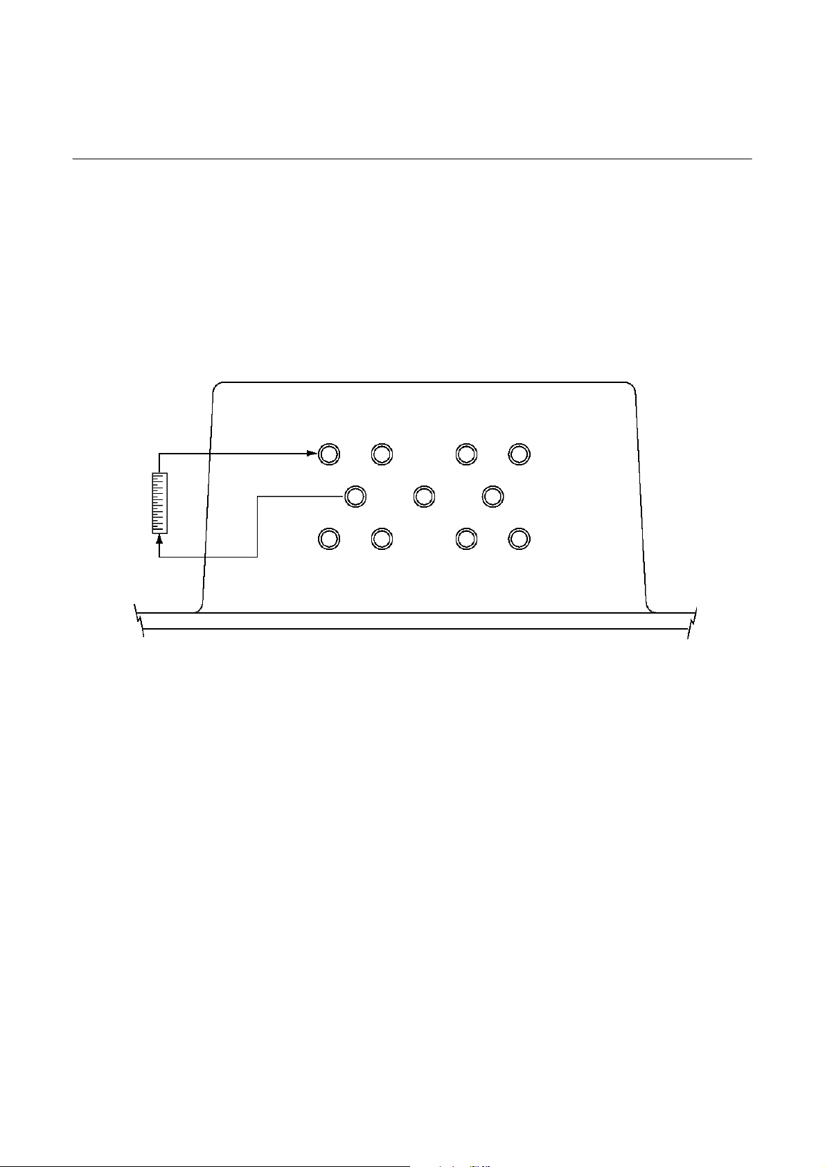
1 2 3 4
Flow Meter*
(option)
567
8 9 10 11
Bottom View
Single or dual channel (Ch) in series:
1 – Gas Inlet (Ch1) 2 – Gas Outlet (Ch1)
Dual channel in parallel:
1 – Gas Inlet (Ch1) 2 – Gas Outlet (Ch1) 3 – Gas Inlet (Ch2) 4 – Gas Outlet (Ch2)
Single or dual channel in series including one auto calibration valve block:
5 – Outlet (Span/Zero/Sample)* 6 – Span Gas 1 Inlet 7 – Span Gas 2 Inlet 8 – Zero Gas Inlet
9 – Sample Gas Inlet
Dual channel in parallel including two auto calibration valve blocks:
1 – Gas Inlet (Ch1) 2 – Gas Outlet (Ch1) 3 – Gas Inlet (Ch2) 4 – Gas Outlet (Ch2)
6 – Span Gas 1 Inlet 7 – Span Gas 2 Inlet 8 – Zero Gas 1 Inlet 10 – Zero Gas 2 Inlet
Option Purge of the CAT housing:
11 – Purge Gas Inlet
* Standard: Outlet = Gas outlet ; Valve block outlet is connected to internal BINOS gas inlet; Option: Valve block
outlet maybe used as outlet for external sample handling (special solution: consult factory)
Figure 2-1. Gas Connections
2-2 Installation Rosemount Analytical Inc. A Division of Emerson Process Management
Page 29
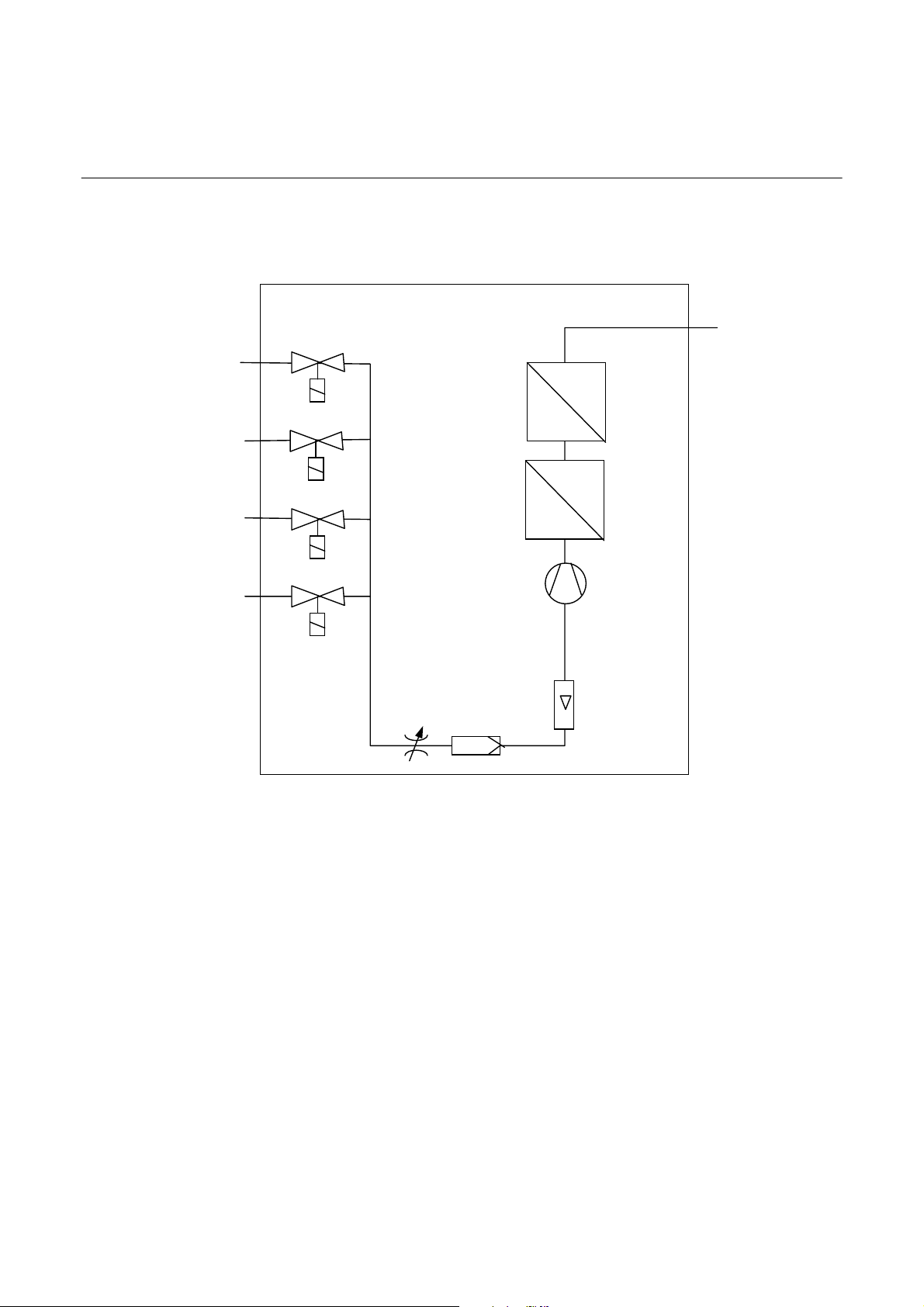
Model CAT100
Span gas 1
Span gas 2
Sample gas
Zero gas
Solenoid Valve
Block
(option)
V1
Channel 2
(option)
V2
V3
V4
Gas Sampling Pump
Throttle and Safety Filter
Channel 1
(option)
(option)
Flow Meter
(option)
Figure 2-2. Piping Diagram (Two channel series)
Instruction Manual
748441-D
April 2002
Gas Outlet
Rosemount Analytical Inc. A Division of Emerson Process Management Installation 2-3
Page 30

Instruction Manual
[
]
[
]
[
A
[
[
[
]
[
]
[
A
748441-D
April 2002
16.00
27.00
685.8]
14.25
362]
25.50
647.7]
.62
[15.7]
1.25
[31.8]
2.25
[57.2]
Figure 2-3. CAT 100 Outline and Mounting Dimensions
406.4
13.00
330.2
MOUNTING HOLE
.625 [15.88] DIA
4 PLC’S
D
C
2.00
50.8
1.00
25.4
D. SAMPLE HANDLING PLATE OPTION. SIZE AND
ARRANGEMENT SUBJECT TO APPLICATION.
C. ELEVEN GAS CONNECTION PORTS (IF REQUIRED
FOR APPLICATION, FLAME ARRESTOR(S) INSTALLED). SEE FIGURE 2-1.
B. ANALOG AND DIGITAL I/O PORTS (M16 x 1.5).
. INCREASED SAFETY JUNCTION BOX.
Note: The Increased Safety Junction Box must be
protected by fuse supply which has a breaking capacity adjusted to the short circuit of the equipment.
2.50
[63.5]
DIMENSIONS
INCH
MM
Model CAT100
3.00
76.2]
2.90
[73.7]
B
2-4 Installation Rosemount Analytical Inc. A Division of Emerson Process Management
Page 31

Model CAT100
Instruction Manual
748441-D
April 2002
a. Gas Conditioning
If the CAT 100 is not supplied with the optional Sample Handling Plate, care must
be taken to ensure that the sample gas is
properly conditioned for successful operation of the various detectors.
All gases must be supplied to the analyzer as conditioned gases! When the
system is used with corrosive gases, it
must be verified that there are no gas
components which may damage the gas
path components.
The gas conditioning must meet the following conditions:
•
Free of condensable constituents
•
Free of dust above 2 µm
•
Free of aggressive constituents
which may damage the gas
paths
When analyzing vapors, the dew point of
the sample gas must be at least 10 °C below the ambient temperature in order to
avoid the precipitation of condensate in
the gas paths.
An optional barometric pressure compensation feature can be supplied for th e
CAT 100. This requires a pressure sensor
with a range of 800 – 1,100 hPa. The
concentration values computer by the detectors will then be corrected to eliminate
erroneous measurements due to changes
in barometric pressure.
The gas flow rate must be in the range of
0.2 l/min to a maximum of 1.5 l/min. A
constant flow rate of 1 l/min is recommended.
NOTE
The maximum gas flow rate for paramagnetic oxygen detectors is 1. 0 l / mi n !
• Temperature and pressure in ac-
cordance with the specifications
Rosemount Analytical Inc. A Division of Emerson Process Management Installation 2-5
Page 32

Instruction Manual
748441-D
April 2002
Model CAT100
2-2 INSTALLATION
CAUTION.
Do not operate or service this instrument
before reading and understanding this instruction manual and receiving appropriate training.
WARNING
ELECTRICAL SHOCK HAZARD
POSSIBLE EXPLOSION HAZARD
Do not open while energized. Do not operate without dome and covers secure. Installation requires access to live parts
which can cause death or serious injury.
CAUTION.
HIGH PRESSURE GAS CYLINDERS
This unit requires periodic calibration with
a known standard gas. It also may utilizes
a pressurized carrier gas, such as helium,
hydrogen, or nitrogen. See General Precautions for Handling and Storing High
Pressure Gas Cylinders, page P-5.
Refer to the installation drawing supplied with
the application data package.
a. Location
The CAT 100 is designed to be installed
in unsheltered environmental locations. It
is recommended that the analyzer be located out of direct sunlight to the extent
possible.
The CAT 100 should be installed as near
as possible to the sample point, in order
to avoid low response time caused by
long sample gas lines.
b. Limitations
See Specification, Section 1-4 (page 1-
11).
c. Gas Lines
For external gas lines, the use of all new
tubing throughout is strongly recommended. The preferred type is new, refrigeration grade copper tubing, sealed at
the ends. Generally, stainless steel tubing
is less desirable as it contains hydrocarbon contaminants introduced through
cleaning. Pre-cleaned and rins ed st ain less steel tubing is available from various
supply houses, and is recommended if
stainless steel is desired.
d. Services
All input power, AC or DC as well as input
and output digital and analog signals connect through the Safety Junction Box located above the CAT 100 dome.
Power Cable
AC Operation: 16 gauge, minimum .
DC Operation: 12 gauge, minimum.
e. Mounting Options
The CAT 100 can be mounted to either 4½ or 6-¼ inch diameter pipe stands. Alternately, the analyzer can be wall or floor
mounted.
Although the CAT 100 is enclosed in an
explosion proof and environmentally
sealed enclosure (NEMA 4X, IP 55), it
should be protected from direct sunlight.
In areas subjected to harsh winter climates, protection should be provided from
rain and snow. A corrugated awning or
other suitable means can be provided to
meet these conditions.
See drawing 660210 located in the rear of
this manual for typical pipe mounting
method. Note that the mounting stand is
an option.
f. Vent Lines
Connect all vent lines (thes e are specified
on the Application Data Sheet) to an ap-
2-6 Installation Rosemount Analytical Inc. A Division of Emerson Process Management
Page 33

Model CAT100
Instruction Manual
748441-D
April 2002
propriate header. The header should have
a means of being purged when venting
dangerous gases. Insure that there is no
backpressure in the vent system as this
will cause variations in the repeatability of
through the Increased Safety Junction
Box. Cable length for these signals
should not exceed 3,000 feet (914 meters), to avoid excessive capacitance
and corresponding signal distortion.
the system.
The following connections are made
g. Electrical Connections
through the Increased Safety Junction
Box:
NOTES
•
1) The enclosure is a NEMA 4X/ IP 55.
All entry locations must be sealed.
2) North American area classification
– Class I Zone 1, Group IIB +H
T4.
2
CENELEC Category 2 – Zone 1,
Group IIB +H
T4.
2
Electrical Power
•
2 Analog Outputs
•
Optional 3 Analog Inputs (for TC
cross compensation)
• 8 Digital Outputs
3) Readily accessible main power
disconnect to be supplied by customer.
4) Electrical installation to be in ac-
• RS 232/RS 485 or Optional
FIELDBUS
•
Optional 3 Relay Outputs
cordance with National Electrical
Code. (ANSI/NFPA 70) and or other
applicable national or local codes.
Connect all required signal cables to
the Increased Safety Junction Box. The
cable entry locations are indicated on
Connections must be made as follows:
USA: ½” Rigid Metal Conduit
European Union: Certified Glands
Canada: Either
the inside cover of the junction box.
The actual electrical connections will
be specified in the Application Data
package. All connections are not necessary for every application.
The Increased Safety Junction Box
must be protected by fuse supply
which has a breaking capacity ad-
All analog/digital inputs and analog/digital/serial outputs are made
justed to the short circuit of the
equipment.
Terminal Description
Top 16 (C-wht) VDC Gnd
Top 17 (C-wht/blk) 0 (2) – 10 VDC [option 0 (0.2) – 1 VDC], Channel 1
Top 18 (C-wht/brn)
0 (4) – 20 mA, Channel 1 (R
≤ 500 Ω)
B
Top 19 (C-wht/red) 0 (2) – 10 VDC [option 0 (0.2) – 1 VDC], Channel 2
Top 20 (C-wht/org)
0 (4) – 20 mA, Channel 2 (R
≤ 500 Ω)
B
Bottom 16 (C-wht/yel) mA return (Gnd)
Bottom 17 (C-wht/grn) mA return (Gnd)
Bottom 18 (C-wht/blu) mA return (Gnd)
Bottom 19 (C-wht/vio) mA return (Gnd)
Table 2-1. Analog Output Terminal Assignments
NOTE
NOTE
Rosemount Analytical Inc. A Division of Emerson Process Management Installation 2-7
Page 34

Instruction Manual
748441-D
April 2002
Terminal Description
Bottom 1 (C-blk) High limit reached, channel 2
Bottom 2 (C-brn) Low limit reached, chan nel 2
Bottom 3 (C-red) High limit reached, channel 1
Bottom 4 (C-org) Low limit reached, chan nel 1
Bottom 5 (C-yel) Gnd
Bottom 6 (C-grn) Valve control, span gas 2
Bottom 7 (C-blu) Valve control span gas 1
Bottom 8 (C-vio) Valve control, zero gas
Bottom 9 (C-gry) Valve control, sample gas
Note: The loading of the open collector digital outputs is a maximum of 30 VDC and 30 mA.
Terminal Description
Bottom 10 (C-wht/gry) OK/Failure (open/closed)
Bottom 11 (C-blk/red) OK/Failure (closed/open)
Bottom 12 (C-blk/org) Measure/Calibration (open/closed)
Bottom 13 (C-blk/yel) Measure/Calibration (closed/open)
Bottom 14 (C-blk/grn) OK/Failure (common)
Bottom 15 (C-blk/blu) Measure/Calibration (common)
Bottom 20 (D-blk/yel) Pump Off/On (open/closed)
Bottom 21 (D-blk/blu) Pump Off/On (closed/open)
Top 21 (D-blk/grn) Pump Off/On (common)
Note: Non-voltage carrying contacts, maximum 30 V, 1 A, 30 W.
Table 2-3. Optional Relay Outputs (Status Signals) Terminal Assignments
Terminal Description
Top 1 (D-blk) Interfering gas 1
Top 2 (D-brn) Interfering gas 1
Top 3 (D-red) Interfering gas 2
Top 4 (D-org) Interfering gas 2
Top 5 (D-yel) Interfering gas 3
Top 6 (D-grn) Interfering gas 3 (Gnd)
Table 2-4. Optional Analog Inputs for TCD Cross Compensation
Model CAT100
Table 2-2. Digital Output Terminal Assignments
2-8 Installation Rosemount Analytical Inc. A Division of Emerson Process Management
Page 35

Model CAT100
Terminal Signal Terminal Signal
Top 7 (D-blu) Gnd Top 11 (D-wht/blk) Gnd
Top 8 (D-vio) RxD Top 12 (D-wht/brn) RxD Top 9 (D-gry) TxD Top 13 (D-wht/red) RxD +
Top 10 (D-wht) Gnd Top 14 (D-wht/org) TxD Top 15 (D-wht/yel) TxD +
Table 2-7. Foundation Fieldbus Terminal Assignments (option)
Connect AC power through a 10 A circuit
breaker that is to be located close to the
CAT 100. The circuit breaker will provide
over current protection as well as a
means of disconnecting the power.
Instruction Manual
748441-D
April 2002
RS 232 RS 485
Table 2-5. Optional RS232/485 Terminal Assignments
Terminal Description
1 (A-brn) Hot
2 (A-blu) Neutral
3 (A-grn/yel) Ground
4 (A-grn/yel) Ground
Table 2-6. Power Connections Terminal Assignments
Terminal Description
1 (B) Field Bus+ (Line)
2 (B) Field Bus- (Neutral)
3 (B) Ground
Foundation Fieldbus (option):
See also Wiring diagram 660198 – CAT
100 BASIC - at the end of this manual as
attachment. This includes all wirings.
Maximum power requirements will be 180
watts, with most applications requiring
less than this amount.
Rosemount Analytical Inc. A Division of Emerson Process Management Installation 2-9
The optional case heater may increase
power requirements to 380 watts.
NOTE
Page 36

Instruction Manual
748441-D
April 2002
Power
EMI Filter Bottom
1 21
1 4
1
Top
21
Figure 2-4. Increased Safety Junction Box Terminals
Model CAT100
NOTE:
If Foundation Fieldbus is selected then another terminal strip will be located between
the power connection and the connector for
the analog/digital/serial inputs and outputs
(consult factory for further information).
2-10 Installation Rosemount Analytical Inc. A Division of Emerson Process Management
Page 37

Model CAT100
Instruction Manual
748441-D
April 2002
2-3 ANALYTICAL LEAK CHECK
If explosive or hazardous gas samples are being measured with the CAT 100, it is recommended that gas line fittings and components
be thoroughly leak-checked prior to initial application of electrical power, bimonthly intervals thereafter, and after any maintenance
which involves breaking the integrity of the
sample containment system.
a. Flow Indicator Method
Supply air or inert gas such as nitrogen,
at 10 psig (689 mbar), to the analyzer
N
2
10 psig
(690mbar)
through a flow indicator wi th a range of 0
to 250 cc/min. Install a shut-off valve at
the sample gas outlet. Set the flow rate to
125 cc/min (ml/min).
Close the outlet shut-off valve and notic e
that the flow reading drops to zero. If the
flow reading does not drop to zero, the
system is leaking and must be corrected
before the introduction of any flammable
sample gas or application of power.
CAT 100 Analyzer
Inlet Outlet
Flow Meter
Gas Outlet
Figure 2-5. Leak check - Flow Indicator Method
Rosemount Analytical Inc. A Division of Emerson Process Management Installation 2-11
Page 38

Instruction Manual
A
748441-D
April 2002
Model CAT100
b. Manometer Method
Install a water-filled U-tube manometer at
the sample gas outlet. Install a shut-off
valve at the sample gas inlet. Admit air or
inert gas to the inlet shut-off valve until
the analyzer is pressurized to approximately 50 hPa. The water column will be
about 500 mm.
Refer to Section 1-4 Specifications
(page 1-11) for maximum pressure
limitations.
For differential measurement, the leak
check must be performed for the
measurement and reference side separately.
For analyzers with parallel gas paths,
the leak check must be performed for
each gas path separately.
CAT 100 Analyzer
Inlet Outlet
N
2
Water
Figure 2-6. Leak Check - Manometer Method
NOTE:
Close the inlet shut-off valve and, following a brief period for pressure equilibrium,
verify that the height of the water column
does not drop over a period of about 5
minutes. If the water column height drops,
the system is leaking and must be corrected before the introduction of any
flammable sample gas or application of
power.
Overpressure
pprox. 50 hPa
2-12 Installation Rosemount Analytical Inc. A Division of Emerson Process Management
Page 39

Model CAT100
Instruction Manual
748441-D
April 2002
SECTION 3
OPERATION
3-1 STARTUP PROCEDURE
Once the CAT 100 has been correctly assembled and installed in accordance with
the instructions in Section 2-2 (page 2-6),
the analyzer is ready for operation.
Before operating the system, verify that the
leak checks have been performed and that
the sample handling unit is performing correctly.
Apply power to the system and verify that
sample gas is flowing.
NOTE
A warm-up time of from 15 to 50 minutes
is required depending on the installed
detector(s).
Analyzer operation can be confirmed by the
illumination of the LED displays through the
glass window on the dome. Upon power up,
the analyzer will perform a self-test routine.
This display will initially show the program
version number, after which the concentration values or error messages will display.
Program version display
(represents any character)
NOTE
In the case of a battery failure in the analyzer, the programmed values will revert
to defaults and the display will flash
“batt” on power up. This message will
disappear after activating any pad. The
battery maintains the memory for programmed parameters when the analyzer
is shut off.
3-2 TOUCHPAD
a. Overview
CAT 100 analyzers intended either to
be used in hazardous area or for outdoor use are provided with a Touch
pad. This version ensures ingress protection (IP) and resistance against mechanical shocks.
The Touch pad design requires special
measures to operate the analyzer in a
safe manner. Due to safety reasons
and to avoid unintended operation, the
infrared sensitivity is adjusted in a way
that the Touch pad may not activate
without using the actuator tool.
b. Elements
Whereas standard front panels are using keys for operating the analyzer, the
Touch pad uses contactless infrared
technology. This results in a slightly
different design.
Each panel key is replaced by two
drilled holes: One for infrared light outlet and another for entry (Figure 3-1,
page 3-1).
IR Outlet
Figure 3-1. CAT 100 Touch pad
IR Entry
Rosemount Analytical Inc. A Division of Emerson Process Management Operation 3-1
Page 40

Instruction Manual
748441-D
April 2002
Model CAT100
c. Actuator Tool
To operate the Touch pad, a Actuator
Tool (PN 42715575) is required.
Figure 3-2 (page 3-2) shows this tool as
it is provided with each analyzer. If a
replacement is required, contact
Rosemount Customer Service Center.
Storing The Actuator Tool
To store the actuator tool, attach the
actuator chain to one of the analyzer
mounting bolts as shown in Figure 3-3
(page 3-2). The mounting provides a
hook to store the actuator tool when not
in use.
Figure 3-3. Storing The Actuator Tool
Figure 3-2. Touch pad Actuator Tool PN 42715575
d. Operation
The Touch pad is operated by reflecting
the infrared light coming out of the drill
hole into the corresponding entry hole.
This is done by holding the actuator
tool’s bent end (Figure 3-2, page 3-2) in
front of the key in a way that is aligned
in parallel to the glass window surface.
A green light (“switch control”) is turned
on when the actuator tool is in the correct position to activate the touch pad.
On the CAT 100 it is placed right above
the keys.
CAUTION.
Do not touch the glass window with the
actuator tool to avoid scratching the
window.
3-2 Operation Rosemount Analytical Inc. A Division of Emerson Process Management
Page 41

Model CAT100
e. Functions
The operation and programming of the
analyzer is performed using the infrared touch pad on the front panel. The
parameters can be adjusted from the
outside the enclosure without having
to remove the dome. This can be accomplished by placing a finger over
the appropriate location directly above
the touch pad on the outside of the
glass window. It is not necessary to
make contact with the glass window.
Instruction Manual
748441-D
April 2002
Position control
Figure 3-4. Touch pad Operation
The stored parameters are maintained
during power off by the means of a
battery powered memory. In the c ase
of a battery failure in the analyzer, the
programmed values will revert to defaults and the display will flash “batt”
on power up. This message will disappear after activating any pad.
After a period of about 60 – 120 seconds in the absence of activating any
pads, the analyzer will automatically
revert to the “analysis display.”
Various prompts will appear on the two
4-digit LED displays.
300ppm
CO
%O
para.
2
FUNCTION ENTER INPUT CONTROL
SPAN 1 SAMPLE 3
SPAN 2 ZERO 4
PUMP SWITCH CTRL.
(channel labels will vary depending on configuration)
Figure 3-5. CAT 100 Analyzer Touch pad Function Identification
Rosemount Analytical Inc. A Division of Emerson Process Management Operation 3-3
Page 42

Instruction Manual
748441-D
April 2002
Model CAT100
f. FUNCTION Touch pad
Activating the FUNCTION pad addresses the individual analyzer Functions in sequence. Addressing an
analyzer Function will not initiate any
analyzer action or operation until the
ENTER pad is activated at the completion of an Input Control entry. The analyzer will continue to perform analysis
throughout touch pad entry procedures.
The following are the analyzer Functions and their sequences:
Zeroing channel 1
Zeroing channel 2
Spanning channel 1
Spanning channel 2
Interval Time for automatic Zeroing
Interval Time for automatic Spanning
Entry of concentration limits
Entry of system parameters
Entry of serial interface parameters
Figure 3-6. CAT 100 Touch pad Functions
1
Only with combination of digital outputs and external solenoid valves, and if Auto = 1.
2
Only with optional RS 232 C/ RS 485 Serial Interface.
1
1
2
3-4 Operation Rosemount Analytical Inc. A Division of Emerson Process Management
Page 43

Model CAT100
g. ENTER Touch pad
The Enter pad is used for the transfer
of numerical data to the corresponding
operating parameters and for the initiation of various operations, such as
zeroing and spanning.
The first time the Enter pad is activated
after selecting one of the Function sequences, the analyzer wi ll ask for a
password code as shown below. This is
to prevent tampering with the settings
by unauthorized personnel. The password code is entered using the Input
Control pads. If an incorrect password
is entered, the CODE display will remain and the entry displayed will be reset to the value of “0.”
Instruction Manual
748441-D
April 2002
Please use a password with two digits.
See also item j for more information.
h. INPUT-CONTROL Touch pads
The Input-Control pads are used for the
adjustment of the individual entry parameter values. Momentary activation
of either pad will increase or decrease
the values by 1.
UP
∆ increases the current value by 1
DOWN
by 1
If either pad is activated and held, the
value will change continuously with the
rate or change accelerating. When the
minimal value is reached, the rate of
change will slow in order to facilitate
entry of the minimal value.
∇ decreases the current value
When the correct password has been
entered, the Enter pad will sequence
through the various entry modes as
shown in Figure 4-2 and as described
in the following sections.
The password has been set to the
value “1” at the factory.
We would recommend to change the
password immediately after start-up for
safety reasons.
Each of the entry parameters is assigned an acceptable tolerance range
which limits the range of values when
entering parameters. In addition, all entries are subjected to a plausibility
check as added protections against
possible entry error.
Rosemount Analytical Inc. A Division of Emerson Process Management Operation 3-5
Page 44

Instruction Manual
748441-D
April 2002
Model CAT100
Optional
Figure 3-7. Analyzer Operating Function Matrix
3-6 Operation Rosemount Analytical Inc. A Division of Emerson Process Management
Page 45

Model CAT100
Instruction Manual
748441-D
April 2002
3-3 ENTRY OF SYSTEM PARAMETERS
To enter any or all of the System Parameters, activate the FUNCTION pad until
appears.
Then activate the ENTER pad.
If the Password Code has not alre ady be en
entered, the following will appear:
Use the INPUT-CONTROL pads to select
the proper Password Code and then activate the ENTER pad.
The following System Parameters will appear in sequence with successive activation
of the ENTER pad. The individual parameters can be changed us ing the INPUTCONTROL pads prior to activating the ENTER pad.
NOTE
An optional pressure sensor with a
range of 800 – 1100 hPa can be incorporated so that the concentration
values will be automatically corrected for barometric pressure. In
this case, it is not possible to enter
the pressure value manually. Any attempt to enter the pressu r e value
manually will be ignored and the
analyzer will automatically revert to
the measured pressure value.
b. Cross Compensation
This control permits switching the
cross-compensation feature on and off.
The cross-compensation feature is designed to minimize mutual interference
between the two gases (i.e. CO
CO) measured by the analyzer.
Entry of 0: Cross-compensation is disabled
and
2
a. Pressure Correction
To eliminate variations in measurement
due to changes in barometric pressure
or sample gas pressure, the current
pressure can be entered expressed in
hPa (mbar) in the range of 800 to 1300
hPa. The concentration values computed by the analyzer will then be corrected to reflect the barometric
pressure or sample gas pressure respectively.
Use the INPUT-CONTROL pads to
change the value and then activate
ENTER.
Rosemount Analytical Inc. A Division of Emerson Process Management Operation 3-7
Entry of 1: Cross-compens ation is enabled
Use the INPUT-CONTROL pads to
change the value and then activate
ENTER.
c. Cross Compensation Calibration
Cross-Compensation correction factors
are automatically determined during
span adjustment if this feature is turned
on. Pure test gases are required for this
operation. Once cross-c omp en sation
corrections have been determine d,
span adjustments may be performed
using test gas mixtures.
Page 46

Instruction Manual
748441-D
April 2002
Model CAT100
Entry of 0: Spanning without crosscompensation correction (test gas mixture)
Entry of 1: Spanning with
compensation correction (pure test
gases)
Use the INPUT-CONTROL pads to
change the value and then activate
ENTER.
To perform a calibration with crosscompensation:
• First perform a zeroing for both channels.
•
Then perform a spanning for both
channels
• Then repeat the spanning for the first
analysis channel
NOTE
Both cross-compensation and
cross-compensation calibration
must be enabled in order to perform
a correct calibration with crosscompensation correction! Use only
pure test gases!
cross-
Entry of 1: The outputs will be locked
during a calibration
Use the INPUT-CONTROL pads to
change the value and then activate
ENTER.
e. Automatic Calibration
This function enables or disables automatic-calibration when the analyzer is
equipped with the optional internal or
external solenoid valves. Digital outputs
are also enabled.
Entry of 0: The outputs remain unlocked
Entry of 1: The outputs will be locked
during a calibration
Use the INPUT-CONTROL pads to
change the value and then activate
ENTER.
f. Tolerance Check
NOTE
When using test gas mixtures,
“C.Cal” must be set to zero!
d. Hold
The Hold function permits keeping the
analog output signals and the concentration limits locked at the last measured values during a calibration
procedure.
Entry of 0: The outputs remain unlocked
3-8 Operation Rosemount Analytical Inc. A Division of Emerson Process Management
The Tolerance function is for the activation and deactivation of the tolerance
check procedure for various calibration
gases. If the tolerance check proced ure
has been activated, during a calibration, the analyzer will indicate if the
calibration shows a deviation of more
than 10% from measuring range of zero
or more than 10% of the nominal concentration value of span.
If this tolerance is exceeded, no calibration will be performed and an error
message will appear.
Entry of 0: Tolerance check is deactivated
Page 47

Model CAT100
Instruction Manual
748441-D
April 2002
Entry of 1: Tolerance check is activated
Use the INPUT-CONTROL pads to
change the value and then activate
ENTER.
g. Display Off
With this function on, the display will be
disabled for about 1-2 minutes after the
last pad activation. If any pad is activated while the Display is off, all display
elements will be turned on without any
further operation being initiated.
Entry of 0: Display is on
Entry of 1: Display is off
Use the INPUT-CONTROL pads to
change the value and then activate
ENTER.
NOTE:
The zero and range values may be
programmed. See Sections 3-3l
(page 3-10) and 3-3m (page 3-10).
For the type of voltage output, refer
to the order confirmation or the identification plate.
See Section 2-2g (page 2-7) for terminal assignments of the analog outputs
in the Increased Safety Junction Box.
i. Flushing Period
The Flushing Period establishes the
dwell time for calibration gas flow
during a calibration before the calibration reading is taken. The period may
be selected in the range of 0-99 seconds depending on the calibration conditions. The calibration gas flow should
be identical with the sample gas flow.
h. Analog Signal Outputs
This function switches the analog outputs from zero reference to life zero
mode. The optically isolated analog
outputs are available on the terminal
block in the Increased Safety Junction
Box.
Entry of 0: Output signal of 0-10 V (option 01- V) / 0-20 mA
Entry of 1: Output signal of 2-10 V (option 0.2-1 V) / 4-20 mA
Use the INPUT-CONTROL pads to
change the value and then activate
ENTER.
Use the INPUT-CONTROL pads to
change the value and then activate
ENTER.
j. User Code
This is the password protection code
used to prevent parameter ch anges by
unauthorized persons. The value is fac tory set to “1” but may then be changed
to another value. Be sure to record the
user code in a safe place.
Use the INPUT-CONTROL pads to
change the value and then activate
ENTER.
Rosemount Analytical Inc. A Division of Emerson Process Management Operation 3-9
Page 48

Instruction Manual
748441-D
April 2002
Model CAT100
k. Response Time
For some types of analysis it may be
desired to change the analyzer damping factor, i.e. its electrical response
time or t90. This function allows the selection of an optimal t90 response time.
The range of acceptable entries is 2-60
seconds.
Use the INPUT-CONTROL pads to
change the value and then activate
ENTER.
If the analyzer is equipped with a second channel, the t90 time for the second channel is also presented for
adjustment.
l. Offset Value
NOTE
The analyzer is supplied from the
factory with the offset set to 0. It is
up to the user to change the valu e if
desired.
m. Range Value
This function allows the user to establish a full scale range for the analog
output signals.
Example:
For an analyzer concentration range of
0-25% it is desired to measure concentrations only in the range of 0-15%. If
the value of 15 is entered here , the
analog signal outputs of 10 (1) V / 20
mA will then correspond to a gas concentration of 15%. The displayed values are not affected.
This function allows the user to establish a scale offset for the analog output
signals.
Example:
For an analyzer concentration range of
0-25% it is desired to measure concentrations only in the range of 10-2 5%. If
the value of 10 is entered here, the
analog signal outputs of 0 V / 0 mA or 2
(0.2) V / 4 mA will then correspond to a
gas concentration of 10%. The dis played values are not affected.
Use the INPUT-CONTROL pads to
change the value and then activate
ENTER.
If the analyzer is equipped with a second channel, the offset for the second
channel is also presented for adjustment.
Use the INPUT-CONTROL pads to
change the value and then activate
ENTER.
If the analyzer is equipped with a second channel, the range for the second
channel is also presented for adju stment.
NOTE
The analyzer is supplied from the
factory with the range set to full
scale concentration range. It is up to
the user to change the value if desired.
n. Reset
3-10 Operation Rosemount Analytical Inc. A Division of Emerson Process Management
Page 49

Model CAT100
Instruction Manual
748441-D
April 2002
The Reset function restores the analyzer settings to the parameters and
calibration factors set in the factory.
This is the equivalent of switching off
the power and disabling the battery retention of the memory by removing the
battery jumper J7.
NOTE:
All parameters and calibration factors entered by the user will be lost
whenever a reset operation is performed
The currently valid user password must
be entered before a reset will be executed.
Use the INPUT-CONTROL pads to enter the password code and then activate ENTER.
Whenever a reset operation is performed, the analyzer operatin g program
will be restarted, just as it is when the
analyzer is first switched on.
Activate the ENTER pad to continue.
p. Serial Number
This function displays the analyzer serial number.
Activate the ENTER pad for the continuation of the serial number.
Activate the FUNCTION pad until the
analyzer is back in the analysis mode.
q. Pump
This function turns the internal pump on
or off. The state of the pump is retained
when the power is shut off.
NOTE:
Jumper J6 on circuit board BKS,
which activates the watchdog circuitry must be inserted if the reset
operation is to be correctly executed. See Section 5-5a, page 5-29.
o. Program Version
This function displays the installed
software version number. This number
is also displayed when the analyzer is
switched on.
Entry of 0: The pump is off.
Entry of 1: The pump is on.
Rosemount Analytical Inc. A Division of Emerson Process Management Operation 3-11
Page 50

Instruction Manual
748441-D
April 2002
Model CAT100
3-4 CALIBRATION
To insure correct analyzer measurement,
zeroing and spanning should be performed
at least once per week . The span calibration must be performed after the zeroing.
For either manual or automatic calibration,
the required test gases must be fed to the
analyzer through the respective gas inlets
with a no-back-pressure flow rate of about
1 l/min, the same as the sample gas.
NOTE:
After switching on the analyzer, wait at
least approximately 15 to 50 minutes
(depending on installed detectors) for
instrument warm up before feeding gas
to the analyzer.
NOTE:
If the optional internal or external solenoid valves are installed, the valves are
automatically actuated by digital outputs
for the respective function. If the analyzer is in “calibration mode,” an optional digital status signal “calibration”
output is activated.
a. Zeroing
For zeroing, the analyzer has to be
flushed with nitrogen (N
quate zero gas such as synthetic or
conditioned air. Air cannot be used for
oxygen zeroing.
b. Spanning
The span gas concentration should be
in the range or 80% to 110% of the full
scale range of the analyzer. If lower
span gas concentrations are used, the
measuring accuracy for sample gas
concentrations higher than the span
gas concentration will be compromised.
Spanning for oxygen measurement can
be done using ambient air as span gas,
if the oxygen concentration is known
and constant.
NOTE
When using span gas mixtures, the
entry for “C.Cal” must be set to “0”
(see Section 3-3c, page 3-7)! If there
is no built-in pressure sensor, the
correct pressure must be entered
before performing the calibration, if
it is desired to have pressure correction (see Section 3-3a, page 3-7)!
) or an ade-
2
3-12 Operation Rosemount Analytical Inc. A Division of Emerson Process Management
Page 51

Model CAT100
Instruction Manual
748441-D
April 2002
3-5 MANUAL CALIBRATION
a. Zeroing
Zeroing will set the actual measured
gas concentration to “zero.”
Activate the FUNCTION pad until the
display shows:
Or
(Zeroing channel 1 or channel 2)
Activate the ENTER pad and the pass-
word code entry screen will appear. Using the INPUT-CONTROL pad, enter
the correct password code and activate
ENTER. The display will now show:
Or
(The actual zero level)
Wait at least the entered flushing time
and t90 time. Then activate the ENTER
pad. The display will now show:
To start the zeroing process, activate
ENTER again. As soon as the zeroing
has finished, the display shows:
Or
(The actual measuring value)
The touch pad will only be released af-
ter another flushing period and t90
time. The analog output signals and the
concentration limits are also released if
Hold = 1.
To leave the calibration mode, activate
FUNCTION.
b. Spanning
Spanning will set the actually measured
gas concentration to the entered span
gas set point. Verification of the span
calibration is essential for accurate
concentration measurement. Spanning
can only be performed after performing
or verifying the zero.
Activate the FUNCTION pad until the
display shows:
Or
(The nominal value)
If the actual and nominal values agree,
zero calibration is not necessary and
the next function can be selected using
the FUNCTION pad.
If the actual and nominal values disagree, activate the ENTER pad and the
display will show:
Or
(The actual measuring value)
Rosemount Analytical Inc. A Division of Emerson Process Management Operation 3-13
Or
(Spanning channel 1 or channel 2)
Activate the ENTER pad and enter the
correct password code if not already
entered. The display will now show:
Or
(The actual concentration level)
Page 52

Instruction Manual
748441-D
April 2002
Model CAT100
Wait at least the entered flushing time
and t90 time. Then activate the ENTER
pad. The display will now show:
Or
(The test gas set point)
If necessary, enter the true test gas set
point value taken from the manufacturer’s certification on the gas bottle using the INPUT-CONTROL pads and
then activate ENTER. The display will
now show:
Or
(The actual measuring value)
If the actual and nominal values agree,
span calibration is not necessary and
the next function can be selected using
the FUNCTION pad.
If the actual and nominal values disagree, activate the ENTER pad to start
the spanning. As soon as spanning has
finished, the display will show:
Or
(The actual measuring value)
The touch pad will only be released af-
ter another flushing period an d t90
time. The analog output signals and the
concentration limits are also released if
Hold = 1.
To leave the calibration mode, activate
FUNCTION.
3-14 Operation Rosemount Analytical Inc. A Division of Emerson Process Management
Page 53

Model CAT100
Instruction Manual
748441-D
April 2002
3-6 AUTOMATIC CALIBRATION (OPTION)
A time-controlled automatic calibration can
be established using internal or external solenoid valves activated by digital outputs.
The automatic function of the analyzer must
also be activated (see Section 3-3e).
With this optional function, the analyzer can
perform an automatic calibration at preset
time intervals. The t-AO and t-AS functions
are available using the FUNCTION pad.
NOTE
For a time-controlled calibration procedure, the test gases must be fed through
solenoid valves controlled by the analyzer in order to ensure the proper supply of test gases in the automatic
calibration sequence.
If the test gas concentration has changed
as a result of a new gas bottle being introduced, the set point must be manually entered per Section 3-5b.
Use the INPUT-CONTROL pads, enter
a time interval in hours when automatic
zeroing is to be performed. The range
of accepted entries in 0 – 399 hours.
Activate the ENTER pad to accept the
entry.
Automatic zero calibration will first be
initiated at the end of the interval entered referenced to the time of entry of
the interval.
b. Combined Zeroing and Spanning
This function establishes an automatic
spanning calibration after the automatic
zero calibration.
Activate the FUNCTION pad until the
following display shows:
Then activate the ENTER pad.
NOTE
If the entry is “0” (zero), the automatic
calibration is switched off.
a. Zeroing
Activate the FUNCTION pad until the
following display shows:
Then activate the ENTER pad.
If the user password c ode has not yet
been entered, .the password entry display will show. Using the INPUTCONTROL pad, enter the correct
password code and activate ENTER.
The display will now show:
If the user password code has not yet
been entered, .the password entry display will show. Using the INPUTCONTROL pad, enter the correct
password code and activate ENTER.
The display will now show:
Using the INPUT-CONTROL pads, enter a time interval in hours when automatic zeroing is to be performed. The
range of accepted entries in 0 – 399
hours. Activate the ENTER pad to accept the entry.
Automatic zero and span calibration will
first be initiated at the end of the interval entered referenced to the time of
entry of the interval.
Rosemount Analytical Inc. A Division of Emerson Process Management Operation 3-15
Page 54

Instruction Manual
748441-D
April 2002
Model CAT100
3-7 CONCENTRATION LIMITS
Upper and lower alarm limits can be established for concentration measurement for
each channel. The rightmost decimal of the
respective display will blink whenever the
concentration value falls outside a limit.
Additional digital signal outputs for alarm
limits are provided on the terminal block inside the Increased Safety Junction Box.
Activate the FUNCTION pad until the following displays:
Then activate the ENTER pad.
If the user password code has not yet been
entered, .the password entry display will
show. Using the INPUT-CONTROL pad,
enter the correct password cod e and ac t i vate ENTER. The display will now show:
Use the INPUT-CONTROL pads to set the
upper limit for channel 1. Then activate the
ENTER pad and the following will appear:
Use the INPUT-CONTROL pads to se the
lower limit for channel 2. Then activate the
ENTER pad and the following will appear:
Use the INPUT-CONTROL pads to se the
upper limit for channel 2. Then activate the
ENTER pad to enter the value.
Activate the FUNCTION pad until the analyzer is back in the analysis display.
Use the INPUT-CONTROL pads to set the
lower limit for channel 1. Then activate the
ENTER pad and the following will appear:
3-16 Operation Rosemount Analytical Inc. A Division of Emerson Process Management
Page 55

Model CAT100
Instruction Manual
748441-D
April 2002
3-8 MEASUREMENT
The following summary steps must be observed for the proper measurement of
sample gas concentration:
• After switching on the analyzer, allow it
to warm up for about 15 to 50 minutes,
depending on the installed detectors.
• Admit sample gas to the gas inlet fit-
ting.
•
Switch on the optional sample gas
pump.
•
Set the gas flow rate to the allowable
range.
•
The analyzer must be in the analysis
mode which is evidenced as follows:
Channel 1 concentration
Channel 2 concentration
(if installed)
If some other display mode has been selected, the analyzer will automatically return
to the analysis display after a period of 60 –
120 seconds has elapsed after the last pad
activation or completion of an operation. Alternately, the user can activate the FUNCTION pad until the analysis mode displays.
Analyzers With Electrochem i ca l O
tector:
The electrochemical O
cell requires a
2
minimum internal consumption of oxygen.
Sample gases with an oxygen concentration of less than 2% could result in a reversible detuning of sensitivity and the
output will become unstable. The recommended practice is to purge the cell with
conditioned ambient air between periods of
measurement. If the oxygen concentratio n
is below 2% for several hours or days, the
cell must be regenerated for about one day
with ambient air. Temporary flushing with
nitrogen (N
) for less than one hour (ana-
2
lyzer zeroing) will have no effect on the
sensitivity or stability.
De-
2
Rosemount Analytical Inc. A Division of Emerson Process Management Operation 3-17
Page 56

Instruction Manual
748441-D
April 2002
Model CAT100
3-9 SHUT DOWN
Before switching off the analyzer, it is recommend to purge the gas lines for abou t 5
minutes with zeroing gas (N
2
conditioned air. For analyzers with electrochemical O
detector, purge all analyzer
2
gas lines with conditioned ambient air before closing any gas line fittings for transport or storage of the analyzer. The full
procedure for shutting down is as follows:
•
Admit zeroing gas to the respective gas
inlet fitting.
•
Switch on the optional gas pump.
•
Set the flow rate to an allowable rate.
) or adequate
After 5 minutes:
• Switch off the analyzer.
•
Shut off the gas supply.
•
Close all gas line fittings immediately.
3-18 Operation Rosemount Analytical Inc. A Division of Emerson Process Management
Page 57

Model CAT100
AL1A
Instruction Manual
748441-D
April 2002
3-10 TEMPERATURE STABILIZATION (OP-
TION)
Higher accuracy of concentration measurement as a function of temperature for
the CAT 100 is achieved through the implementation of a controlled heater temperature within the enclosure. The
temperature controller is mounted to the top
of the analyzer and can be seen through
the window.
The internal temperature of the analyzer is
factory set to 50 °C. This internal temperature is suitable for ambient temperatures of
up to 45 °C (50 °C max.).
For higher or lower expected ambient temperatures, the internal analyzer temperature can be set to the highest expected
value but not above 50 °C. For instance, if
the ambient temperature is not expected to
exceed 30 °C, the temperature controller
can be set to 30 °C, resulting in longer life
for the heaters and temperature controller.
NOTE
If the temperature is changed from the
factory setting of 50 °C, then the analyzer must be re-calibrated at the newly
set temperature. See Sections 3-4 (page
3-12), 3-5 (page 3-13) or 3-6 (page 3-15)
for calibration procedures.
a. Changing Temperature Settings
To change the internal temperature setting, remove the dome housing and adjust the set point to the desired value as
described below.
SP2
L2
°
°
C
F
MENU / MAX / MIN ENTER
Figure 3-8. Temperature Controller
1. Press MENU once. The display will
flash the first digit of the set point.
2. Press MAX to set the digit from 0 to
9.
3. Press MIN to activate the next digit.
SV
NOTE
When equipped with this temperature
stabilization option, allow the analyzer
to reach operating temperature before
making valid gas concentration meas-
4. Repeat these steps to set the other
digits.
5. Press ENTER to store the setting
and return to run mode.
urements. The ramp rate of the temperature controller is 20 °C/hr so adjust
warm up time according to the am bient
temperature and the controller set point.
Rosemount Analytical Inc. A Division of Emerson Process Management Operation 3-19
Page 58

Instruction Manual
748441-D
April 2002
Model CAT100
b. Controller Settings
If it is ever necessary to replace the
temperature controller or if the settings
get changed, the following describes
the default settings that must be configured and the procedure to configure
it properly.
Omega Engineering model CN77322
Controller settings for CAT 100:
DIP switch settings:
The DIP switch is accessible through
an opening on the side of the case. After carefully removing the controller
from the case, locate the DIP switch
and set the switches according to the
following:
ON OFF
Initial menu settings:
Upon applying power, the controller will
first flash reset on the PV display and
the software version number on the SV
display, and then begin the Run Mode.
Immediately press the MENU key to
enter the Configuration Mode so that
the controller does not begin to apply
heat to the CAT 100. Alternately, press
the ENTER key twice to enter the
Standby Mode.
87654321
3-20 Operation Rosemount Analytical Inc. A Division of Emerson Process Management
Page 59

Model CAT100
Mnemonic Description Menu Navigation (x = multiple presses)
SP1 = 50 Temperature set point 1 = 50 MENU-MAX-MIN-ENTER
SP2 = 50 Temperature set point 2 = 50 MENU-MENU-MAX- MIN-ENTER
51.o.1 = 51.o.1 Output redirection = output 1 to 1 MENU-MENU-MENU-MAX- ENTER
InPt tYPE = t.c Input Type = Thermocouple MENUX-ENTER-MAX-ENTER
t.c = J Thermocouple type = J ENTER-MAX-ENTER
dC.Pt = FFF.F Decimal Point = FFF.F MENUX(rdG CnFG)-ENTER(dEC.Pt)-ENTER-MAX-ENTER
tEnP = C Temperature Units = C ENTER-MAX- ENTER
FLtr = 0004 Filter Constant = 4 ENTER-MAX-ENTER
Alr.1 = dSbL Alarm 1 = disable MENUX-ENTER-MAX-ENTER-ENTER
L.b.AL = dSbL Loop Break Alarm = disable MENUX-ENTER-ENTER-MAX-ENTER-ENTER
Id = dSbL ID Number = disable ENTER-ENTER-MAX-ENTER
SELF = dSbL Manual, Self Control = disable MENUX(Out 1)-ENTER-MAX
o0L0 = 0000 Percent Low = 0 MIN/MAX-ENTER
o0HI = 0099 Percent High = 99 MIN/MAX-ENTER
CtrL = On.OF Control Type = On, Off ENTER-MAX-ENTER
Actn = rur5 Action Type = Reverse Acting ENTER-MAX-ENTER
dEAd = 001.0 Dead Band = 1.0 ENTER-MAX/MIN-ENTER
rANP = dSbL Ramp and Soak = disabled MENUX(rANP SoAC)-ENTER-ENTER-MAX-ENTER
Final menu settings:
Make sure the controller is in Run Mode. Allow the heater to reach the 50 C set point temperature.
Enter the Configuration Mode again and change the following settings.
Instruction Manual
748441-D
April 2002
Mnemonic Description Menu Navigation (
CtrL = PId Control Type = PID MENU-ENTERx(CtrL tYPE)-ENTER-MAX-ENTER
Actn = rur5 Action Type = Reversing Action ENTER-MAX-ENTER
AUto = EnbL Auto PID = Enabled ENTER-MAX-ENTER
AdPt = EnbL Adaptive Control = Enabled ENTER-MAX-ENTER
Antl = EnbL Anti-integral = Enabled ENTER-MAX-ENTER
Strt = dSbL Start Auto PID = Disabled ENTER-MAX-ENTER
CYCL = 0007 Cycle Time = 7 Seconds ENTERx(CYCL timE)-MAX/MIN-ENTER
dPnG = 0004 Damping Factor = 4 ENTER-MAX-ENTER
rANP = dSbL Ramp and Soak = Disable MENUx(rANP SoAC)-ENTER-MAX-ENTER
x
= multiple presses)
Rosemount Analytical Inc. A Division of Emerson Process Management Operation 3-21
Page 60

Instruction Manual
748441-D
April 2002
Model CAT100
3-22 Operation Rosemount Analytical Inc. A Division of Emerson Process Management
Page 61

Model CAT100
Instruction Manual
748441-D
April 2002
SECTION 4
SERIAL INTERFACE OPTION
4-1 OVERVIEW
The CAT 100 analyzer can be equipped with
a serial interface, enabling communication
with a host computer. The host computer can
read and alter parameters, as well as initiate
analyzer operations, using standardized protocols. The option BSI circuit board constitutes the hardware interface. This can be
configured as RS 232 C or as RS 485. The
RS 485 interface permits the n etworking of
several analyzers. Each analyzer may then be
addressed using an assigned numerical ID
code.
Communications are always initiated by the
host computer. Thus, the analyzer is a passive device whereby the host requests information or takes an action such as changing
parameters.
Communications between the host computer
and the analyzer(s) is carried out with the
transmission of a character string containing a
specific syntax. The string always starts with
the “$” (start character), immediately followed
by a three-digit instruction code. Subsequent
elements of the string are separa ted by the “:”
hyphen character. The final element of all
strings must be the “CR” carriage return character (terminate character).
Upon receipt of the terminate character, the
analyzer attempts to evaluate the current contents of its input buffer as a valid string. If the
syntax of the transmitted string is correct, the
analyzer will transmit a response string to the
host computer. This consists of the s tart character, an instruction code, requ ested data, a
block-parity byte, and the termination character.
If the syntax of the transmitted string was not
correct, the analyzer will transmit to the host
computer a status string containing an error
message. Each terminate character receipt
thus initiates an analyzer response.
To avoid detecting transmission errors, the
host computer can inset a message-len gt h
parity byte immediately prec eding the terminate character for verification b y the analyzer.
The analyzer always transmits messagelength parity bytes immediately preceding
termination characters.
The elapsed time between reception of start
characters and termination characters is not
limited by the analyzer; i.e., there is no timeout period.
If the host computer transmits any new characters before the analyzer has responde d to
the preceding string, the analyzer’s input
buffer will reject them; i.e., these characters
will be ignored by the analyzer. The analyzer
software is configured such that strings may
be sent to the host computer at time intervals
of 150 ms or greater.
The transmission rate may be set between
600 and 4800 baud.
An echo-mode may also be activated.
Rosemount Analytical Inc. A Division of Emerson Process Management Serial Interface Option 4-1
Page 62

Instruction Manual
748441-D
April 2002
Model CAT100
4-2 PROTOCOLS
The analyzer is supplied from the factory with
either PCB SIF232 or SIF485 connected to
PCB BSI 10. This can be changed in the field.
The parameter 232c is also set to 0=NO or
1=YES.
a. RS 232
This interface required a shielded cable
having at least three internal conductors.
b. RS 485
Configuration for either 2-wire or 4-wire
operation is selected from LB1 on PCB
SIP485. Connect pins 1-2 for 2-wire operation or pins 2-3 for 4-wire operation.
For network operation with several analyzers, jumper P2 must be installed at
each end of the network. Analyzers inbetween must hav e P2 removed.
In contrast to RS232C operation, simultaneous transmission and reception is not
implemented. Although there would be no
damage to the electronics, simultaneous
transmission and reception co uld lead to
destruction of data. In this mode, the analyzer acts passively; i.e., it keeps its
transceiver set for reception whenev er it
is not transmitting. Since the time period
for transmission and reception are estab lished by protocols, data collisions are
prevented.
4-2 Serial Interface Option Rosemount Analytical Inc. A Division of Emerson Process Management
Page 63

Model CAT100
Instruction Manual
748441-D
April 2002
4-3 SETTING INTERFACE PARAMETERS
a. ON/OFF Status
The analyzer may be set to either “online” or “off-line” status. This setting may
be performed either from the touch pad or
by string instruction.
Status
On-Line
Status
Off-Line
Status
If the analyzer is set to “off-line”
status, it will accept only instruction
code 6 from the host computer. All
other instructions will be ignored and
result in the transmission of the appropriate status strings.
b. Communication Parameters
The communication parameters between
the analyzer and the host computer must
agree for error-free communications. The
following analyzer parameters can be set:
Baud rate: 600 / 1200 / 2400 / 4800
Data bits: 8
Stop bits: 2
Parity bit: none
Echo mode: on / off (received charac-
LPB-test: on / off (message length
ID-number: 0 to 99 (device ID-number
Touch pad String
On.-L = 1 Code 6
On.-L = 0 Code 7
ters will be retransmitted
immediately)
parity check)
in RS485 mode)
Settings
NOTE
All entries are made us the INPUTCONTROL pads and the ENTER pad.
Activate the FUNCTION pad until:
appears. Then activate ENTER.
If the Password Code has not alre ady
been entered, the following will appear:
Use the INPUT-CONTROL pads to select
the proper Password Code and then ac tivate the ENTER pad.
The analyzer is now ready for code entry
by entering the following parameters and
activating ENTER between each entry:
0 = off-line status
1 = on-line status
For RS485 operation only, each device is assigned a
device number of 0-
99.
Select interface
type:
0 = RS485
1 = RS232C
Set baud rate:
0 = 4800
1 = 2400
2 = 1200
3 = 600
Echo-mode operation:
0 = OFF
1 = ON
Message-block parity check:
0 = OFF
1 = ON
Rosemount Analytical Inc. A Division of Emerson Process Management Serial Interface Option 4-3
Page 64

Instruction Manual
748441-D
April 2002
Model CAT100
4-4 STRING SYNTAX
Start Character (“$” = Hex 24)
If the start character is missing, this will result
in transmission of the correspond status string
by the analyzer.
Terminate Character (“CR” = Hex OD)
If the terminate character is missing, no decoding of the transmitted information will be
performed and the analyzer will not respond.
No response message will be transmitted.
Instruction Code
Each instruction is assigned a unique threedigit instruction code. If a received instruction
code should be other than three digits in
length or contain non-numerical ASCII charac-
ters, the analyzer will transmit an appropriate
status string. Reception of unassigned instruction codes will also result in the transmittal of
a status string.
In the RS232C mode of operation, the instruction code immediately follows the start character. In the RS485 mode of operation, the start
character is followed by a two-digit device
identification code, the separator character “;”
and a three-digit instruction code, in that order.
Hyphen Character (“;” = Hex 3B)
Individual elements of a string line are separated by the hyphen character. Missing hyphen characters can lead to misinter pretat ions
of the strings, and will result in transmission of
a corresponding status string.
4-4 Serial Interface Option Rosemount Analytical Inc. A Division of Emerson Process Management
Page 65

Model CAT100
Instruction Manual
748441-D
April 2002
a. Status Strings
If string syntax from the host computer is
faulty, or the analyzer is unable to act on
a received instruction, the analyzer will
transmit a status string to the host computer as follows:
Status String
$ID;000;S100;LPB<CR> Unrecognized instruction code
$ID;000;S101;LPB<CR> LP-byte in error
$ID;000;S102;LPB<CR> Start character missing
$ID;000;S103;LPB<CR> Input buffer overflow
$ID;xxx;S104;LPB<CR> Analyzer off-line status
$ID;xxx;S105;LPB<CR> Text line too long
$ID;xxx;S106;LPB<CR> Undefined instruction
$ID;xxx;S107;LPB<CR> Invalid integer value
$ID;xxx;S108;LPB<CR> Numerical value outside defined range
$ID;xxx;S109;LPB<CR> Invalid failure/status code
$ID;xxx;S110;LPB<CR> Instruction cannot be done here
$ID;xxx;S111;LPB<CR> Failure in transmitted character
$ID;xxx;S112;LPB<CR> Zeroing running
$ID;xxx;S113;LPB<CR> Spanning running
$ID;xxx;S114;LPB<CR> Invalid real number
$ID;xxx;S115;LPB<CR> Automatic calibration mode off
$ID;xxx;S116;LPB<CR> Parameter outside defined range
$ID;xxx;S117;LPB<CR> Pre-Flushing period is running
Where:
xxx: Instruction code
ID: Device ID number in RS485 mode
LPB: Message-length parity byte
<CR>: Terminate character
Description
Rosemount Analytical Inc. A Division of Emerson Process Management Serial Interface Option 4-5
Page 66

Instruction Manual
748441-D
April 2002
Model CAT100
b. Numerical Representations
Strings may contain integers or real numbers. The formats for these numbers are
subject to the following restrictions:
Integers
Maximum value = 2
Only positive numbers are accepted
No decimal points allowed
Real
Maximum of 6 digits accepted
No alphabetic characters allowed
Analyzer output are 6-digit real
numbers
16
– 1
c. Block Parity Check
The host computer may insert a message-length parity byte into the strings.
These must be two characters.
The message-length parity byte is the
cumulative exclusive-or correlation of all
previously transmitted characters of the
string line. Representation is in hexadecimal format. For example, if the decimal value should be 13, the messagelength parity byte will be represented by
the two characters “OD,” o30H and o44H.
The block parity check may be enabled or
disabled at the analyzer (see Section 4).
4-6 Serial Interface Option Rosemount Analytical Inc. A Division of Emerson Process Management
Page 67

Model CAT100
4-5 INSTRUCTION (RECEIVE) SYNTAX
Code definitions:
RP: Rec eive parameters (analyzer is accepting values)
SP: Send parameters (analyzer is sending values)
RI: Receive instructions
k: Channel numbers 0 to 1
m: Range number (always 1)
w: Value
<ID>: Device ID number in RS485 mode
LPB: Message-length parity byte
<CR>: Terminate character
a. Instruction Listing
Receipt of any instruction code not listed will be acknowledged by transmittal of status code 106. Future enhancements will make use of code numbers not currently in use.
Instruction Manual
748441-D
April 2002
Instruction String
$ID;001;k;LPB<CR> RI stand-by status
$ID;002;k;LPB<CR> RI sample gas valve open
$ID;003;k;LPB<CR> RI zeroing gas valve open
$ID;005;m;k;LPB<CR> RI span gas valve open
$ID;006;LPB<CR> RI on - line status
$ID;007;LPB<CR> RI off - line status
$ID;011;m;k;LPB<CR> SP at full scale range
$ID;013;k;LPB<CR> SP t90 (response time)
$ID;014;w;k;LPB<CR> RP t90 (response time)
$ID;017;k;LPB<CR> SP pre-flushing period
$ID;018;w;k;LPB<GR> RP pre-flushing period
$ID;019;k;LPB<CR> SP Pre-Flushing period
$ID;020;w;k;LPB<CR> RP Pre-Flushing period
$ID;023;k;LPB<CR> SP concentration
$ID;028;m;k;LPB<CR> SP span gas concentration
$ID;029;w;m;k;LPB<CR> RP span gas concentration
$ID;030;LPB<CR> SP status messages
$ID;031;t;LPB<CR>
$ID;603;k;LPB<CR> SP gas component
$ID;604;k;LPB<CR> RI automatic zeroing
$ID;605;k;LPB<CR> RI automatic spanning
$ID;606;0;LPB<CR> RI automatic zeroing and spanning
$ID;627;LPB<CR> SP failure message (possible error batt. is clearing by read out)
$ID;645;0;LPB<CR> SP pressure value
$ID;646;w;LPB<CR>
Description
SP serial number (t=0, max. 10 characters)
channel identification (t=1: ch.1, t=2: ch. 2)
SP solenoid valve status (w=1: Sample gas valve w=2: zero gas valve,
w=4: span gas 1, w=8: span gas 2)
Rosemount Analytical Inc. A Division of Emerson Process Management Serial Interface Option 4-7
Page 68

Instruction Manual
748441-D
April 2002
b. Response String Syntax
Response strings follow with the same syntax as the appropriate (SP-) commands.
The response string for instruction:
$ID;030;LPB<CR> SP Status messages
Is as follows:
$ID;030;a;b;c;LPB<CR>
Where:
Model CAT100
Value
a: OK-Status 0 Relay without power
1 Relay active
b: Calibration 0 No calibration
1 Zeroing channel 1
2 Zeroing channel 2
3 Zeroing channel 1 + 2
4 Spanning channel 1
5 Spanning channel 2
6 Spanning channel 1 + 2
7 Spanning channel 1 first, then channel 2
8 Reserved
9 Reserved
10 Waiting for flushing time and t90 response time
c: Relay 3 0 Relay without power
1 Relay active
Meaning
4-8 Serial Interface Option Rosemount Analytical Inc. A Division of Emerson Process Management
Page 69

Model CAT100
Instruction Manual
748441-D
April 2002
SECTION 5
MAINTENANCE AND SERVICE
DANGER.
POSSIBLE EXPLOSION HAZARD
If explosive or hazardous gas samples are
being measured, it is recommended that
gas line fittings and components be thoroughly leak-checked prior to application of
electrical power, bimonthly intervals, and
after any maintenance which involves
breaking the integrity of the sample containment system. Leakage of flammable
samples could result in an explosion. See
Sections 2-3 (page 2-11) and 6-2 (page 5-6)
for Analytical Leak Check.
5-1 OVERVIEW
Maintenance of the CAT 100 can be summ a rized into three categories as follows:
a. Operating Factors
Many times a fault can be traced to
operational omissions. Refer to the
Troubleshooting Guide in Section 6 for
tips on isolating typical faults. Also refer to
Section 2 Installation and Section 3 Operation to verify that the analyzer is being
operated properly.
Likewise, some faults can be traced to
ancillary equipment. Check all equipment
which is connected to the CAT 100, especially all gas paths, both sample and calibration.
b. Analyzer Replacement
The CAT 100 is uniquely designed so that
the analyzer component can be eas ily
removed from the explosion proof housing
and replaced. For critical service applications, a spare analyzer can be maintained
and replacement can be effected in a
matter of minutes to have the process
back into operation with minimal interruption.
c. Analyzer Repair
Ultimately, the analyzer component may
need maintenance and/or service. See
the Troubleshooting Guide in Section 6
for typical failure remedies, Section 5 for
maintenance operations, and service of
analyzer internal components. Refer to
the CAT 100 Assembly Drawing 659921
located in the rear of this manual.
Rosemount Analytical Inc. A Division of Emerson Process Management Maintenance and Service 5-1
Page 70

Instruction Manual
748441-D
April 2002
Model CAT100
5-2 COMPONENT REMOVAL
DANGER.
POSSIBLE EXPLOSION HAZARD
If explosive or hazardous gas samples are
being measured with the CAT 100, it is recommended that the system be purged with
air or inert gas such as nitrogen before
opening the explosion proof housing.
Failure to purge the housing before opening could result in an explosion.
WARNING.
ELECTRICAL SHOCK HAZARD
Disconnect power from the CAT 100 before
opening and removing any components.
Failure to remove power can result in electrical shock.
The CAT 100 explosion proof enclosure is
comprised of three major sections; the base,
the extender housing and the dome housing.
These are shown in Figure 5-1 (page 5-2).
The three sections are threaded together. To
remove, turn counterclockwise and to replace
turn clockwise. Use an anti-seizing compound
on the threads when required.
O-Ring
Base
Retaining Ring
Extender Housing
O-Ring
Dome Housing
Glass Window
Figure 5-1. CAT 100 Enclosure Assembly
5-2 Maintenance and Service Rosemount Analytical Inc. A Division of Emerson Process Management
Page 71

Model CAT100
Instruction Manual
748441-D
April 2002
a. Analyzer Removal
1. Refer to drawing 659921 for location
of components.
2. Remove only the dome housing from
the extender ring.
3. Mark the location of the screws on
each analyzer mount using a fine tip
marker. It is important that the analyzer be replaced in the exact same
location so that the light guides touch
the inside of the glass window.
4. Loosen, do not remove, the screws
(17) holding the swing tab (14) on
each analyzer mount (2) and swing
the tab clear of the slot.
5. Loosen, do not remove, the six
screws (23) holding the analyzer.
6. Slide the analyzer forward being careful of the umbilical cables and gas
lines attached.
7. Disconnect all electrical connections
and gas lines and remove the analyzer component for repair or replacement.
8. Close all gas line fittings with PVC
caps after removal of the analyzer.
2. Locate the analyzer in the exact same
location as when removed by aligning
the screws with the alignment marks
previously made.
3. Tighten the screws.
4. Make sure the dome threads are
clean and free of any contaminants.
5. Replace the dome housing, by lining
up the reference marks so that the
threads engage properly. If any resistance is felt, remove the dome and
clean the threads.
6. Make sure that the spring loaded light
guides just touch the inside of the
glass window. Failure to have the light
guides touching the glass window can
result in spontaneous menu navigation.
c. Power Supply Assembly Removal
1. Follow the process for analyzer removal in Section 5-2a (page 5-3).
2. Disconnect all wires from the power
supply terminal block.
3. Loosen, do not remove, the three
screws (17) holding the power supply
assembly.
b. Analyzer Replacement
1. Slide the analyzer onto the mounts,
being careful that the screws and
washers are on the outside.
Rosemount Analytical Inc. A Division of Emerson Process Management Maintenance and Service 5-3
4. Slide the power supply assembly in its
slotted holes and remove.
5. Reverse the process for installation.
Page 72

Instruction Manual
748441-D
April 2002
Model CAT100
5-3 ANALYZER CONFIGURATION AND AD-
JUSTMENT
The following is a brief description of the internal hardware of the analyzer to familiarize
the maintenance technician with the location
of parts for service. It should be understood
that this is an example only, as the configuration of the analyzer can depend on the install
detectors and number of channels, one or
two.
a. Component Layout
Depending on the installed options, the
analyzer can include the following detectors:
• One Infrared Photometer
• One 02 Sensor (paramagnetic or elec-
trochemical)
•
Two Infrared Photometer
•
One 02 Sensor (paramagnetic or electrochemical) and one Infrared Photometer
In addition, the following major components may be present:
• Gas sampling pump with a maximu m
pumping rate of 2.5 l/min (not included
on two channel analyzer with parallel
gas paths). An indicator light is provided
on the front panel to show when the
pump is on.
•
Option pressure sensor (range of 800 to
1100 hPa). With the pressure sensor installed, the concentrations values computed by the analyzer will be corrected
to reflect the barometric pressure to
eliminate faulty measurements due to
changes in barometric pressure.
•
An optional solenoid valve unit (not included on two channel analyzer with
parallel gas paths).
• For this example, there are 4 built-in so-
lenoid valves: Sample Gas, Zero Gas,
Span Gas 1, and Span Gas 2.
•
An indicator light on the front panel
shows if a solenoid valve is open.
The location of these major components
are show in Figure 5-2 through Figure
5-5.
5-4 Maintenance and Service Rosemount Analytical Inc. A Division of Emerson Process Management
Page 73

Model CAT100
(
p
Solenoid
Valves
FOUNDATION
Fieldbus
(option)
Digital Inputs
(option)
Paramagnetic
Oxygen Sensor
(depending on ana-
Figure 5-2. Analyzer Component Layout (Infrared Channel / Oxygen Measurement, Combined)
(Channel 1, alt)
(Channel 2)
Front Panel
Instruction Manual
748441-D
April 2002
Circuit board BKS
under photome-
IR Photometer
(depending on ana-
Electrochemical Oxygen
Sensor with circuit board
OXS
Pressure Sen-
Gas Sampling
Pum
Rosemount Analytical Inc. A Division of Emerson Process Management Maintenance and Service 5-5
Page 74

Instruction Manual
748441-D
April 2002
Solenoid
Valves
FOUNDATION
Fieldbus
Digital Inputs
(option)
Figure 5-3. Analyzer Component Layout (1 Channel Oxygen Measurement, Electrochemical)
Model CAT100
Circuit board BKS
(Channel 1)
Electrochemical
Oxygen Sensor
with circuit board
Pressure Sen-
Gas Sampling
Pump
Front Panel
5-6 Maintenance and Service Rosemount Analytical Inc. A Division of Emerson Process Management
Page 75

Instruction Manual
(dep
(dep
y
y
Model CAT100
Solenoid
Valves
FOUNDATION
Fieldbus
Digital Inputs
(option)
Thermal Conductivit
Thermal Conductivit
Paramagnetic Oxygen Detector
ending on ana-
Figure 5-4. Analyzer Component Layout (Paramagnetic Oxygen Measurement / Thermal Conductivity,
Combined)
Front Panel
Circuit board BKS
Thermal Conductivity Detector
ending on ana-
Pressure Sen-
Gas Sampling
Pump
748441-D
April 2002
Rosemount Analytical Inc. A Division of Emerson Process Management Maintenance and Service 5-7
Page 76

Instruction Manual
(dep
y
y
(
748441-D
April 2002
Solenoid
Valves
FOUNDATION
Fieldbus
Digital Inputs
(option)
Thermal Conductivit
Thermal Conductivit
(Channel 1)
Channel 2,
Thermal Conductivity Detector
ending on ana-
Figure 5-5. Analyzer Component Layout (Infrared Channel / Thermal Conductivity, Combined)
(Channel 2)
Front Panel
Model CAT100
Circuit board BKS
IR Photometer
(depending on ana-
Electrochemical
Oxygen Sensor
with circuit board
Pressure Sen-
Gas Sampling
Pump
5-8 Maintenance and Service Rosemount Analytical Inc. A Division of Emerson Process Management
Page 77

Model CAT100
Instruction Manual
748441-D
April 2002
b. Photometer Assembly
Depending on the gas component being
measured and the concentration range,
different photometer assemblies will be
installed in the analyzer. In addition, a
sealed photometer can be supplied in
which case all parts are sealed with Orings.
The entire photometer assembly is
mounted as a unit on the main circuit
board (BKS) by means of a bracket. The
main circuit board is inserted into guide
rails in the analyzer housing, to which the
front panel and rear panel are attached.
Photometer with Pyroelectrical Detector (Solid-State Detector)
Figure 5-6 (page 5-10) shows the layout
of the photometer assembly for a dual
channel configuration.
The base element for the photometer assembly is the chopper housing (03), on
which the light source (thermal radiator,
07), the analysis cell (cuvette, 09), and
the signal detection unit [filter cell (14/15),
pyroelectrical (solid-state) detector with
integrated preamplifier (16)] are all
mounted. The chopper hous ing al s o incorporates the duplex filters (04/05) for
the selection of spectral band-pass
ranges from the broadband emission of
the light sources.
Between the two halves of the chopper
housing (03), which are sealed together
with an 0-ring, is the chopper blade,
driven by a stepping motor. Both the
chopper housing and the motor encapsu-
lation are hermetically sealed with respect
to ambient in order to prevent entry of
gases such as atmospheric CO
which
2
could produce background absorptivity
(pre-absorption), leading to drift effects. An
absorber material provides for constant
removal of any traces of C0
which may
2
enter the interior of the chopper housing
by diffusion.
The chopper housing additionally incorporates a photoelectric gate for providing a
reference signal for the phase angle of
the chopper blade, plus a temperature
sensor (28) for continuously monitoring
the photometer assembly temperature.
This temperature information is used by
the signal processing electronics for the
compensation of thermal effects.
The analysis cells are merely aluminum
tubes equipped with sample gas inlet and
outlet fittings. This extremely simple and
windowless design enables easy cleaning
of the cells in the event of contamination.
The only optical surfaces which also
might become contaminated are the
chopper windows and the windows of the
filter cells; these are accessible upon removal of the cell body.
The filter cell (14/15) has a necked conical shape for optimal adaptation of the
analysis cell beam cross-sectional profile
to the active area of the detectors.
For high measurement ranges (up to
100%)
an adapter cell (10) is required.
,
The use of a spacer ring (08) creates an
analysis cell in the space between the exit
window of the adapter cell and the entrance window of the filter cell.
Rosemount Analytical Inc. A Division of Emerson Process Management Maintenance and Service 5-9
Page 78

Instruction Manual
748441-D
April 2002
06
28
17
26
Model CAT100
Legend:
03 Chopper Housing
04/05 Duplex Filter Disc
06 Zero Adjustment Baffle (not in sealed photometer)
07 Light Source (thermal radiator)
08 Analysis Cell 1-7 mm (spacer ring)
09 Analysis Cell 50-200 mm
10 Adapter Cell
14/15 Filter Cell
16 Detector
17 Flange (light source)
18-21 O-Rings
22 Clamp (analysis cells 1-7 mm)
23 Clamping Collar (analysis cells 1-7 mm)
25 Clamp (analysis cells 50-200 mm)
26 Light Source Mounting Screws
27 Mounting Screws for Analysis Cells / Adapter Cells
28 Temperature Sensor
16
19
14
21
25
22
09
03
10
18
03
05
Figure 5-6. Photometer Assembly with Pyroelectrical Detector
16
19
15
23
08
21
10
20
5-10 Maintenance and Service Rosemount Analytical Inc. A Division of Emerson Process Management
Page 79

Model CAT100
A
r
Instruction Manual
748441-D
April 2002
Photometer with Gas Detector
Figure 5-7 (page 5-11) shows the layout
of the photometer assembly. This assembly is similar to the assembly with pyroelectrical detector.
The analysis cells are separated into two
halves by means of an internal wall along
its axis and both ends are sealed with
windows. This divides the analysis cell
into measuring side and reference side.
Sample gas flows through the measuring
side while the closed reference side contains inert gas (N
).
2
High Measuring Range Combined With Electrochemical O
nalysis
Filter
Cell
Gas
Detector
Low Measuring Range Combined With Electrochemical O
Analysis Cell
Absorber
Preamplifier
Figure 5-7. Photometer Assembly with Gas Detector
To prevent measuring errors by preabsorption. Two absorbers, fitted to the
gas connectors of the reference side, absorb CO
The filter cell has a single-stage conical
shape. The gas detector is connected by
a shielded cable to a preamplifier. For
small measuring ranges, the preamplifier
is mounted at the analysis cell. For high
measuring ranges, the preamplifier is
mounted by two holding clamps.
Measurement
2
Holding
Device
Measurement
2
Preamplifie
components.
2
Holding
Device
Holding
Device
Absorber
Gas Detector
Filter
Cell
Rosemount Analytical Inc. A Division of Emerson Process Management Maintenance and Service 5-11
Page 80

Instruction Manual
748441-D
April 2002
c. Analyzer Rear Panel
1 2 3 4 5 6 7 8 9
K1 K2 K1 K2
IN OUT
ANALOG IN
X1 OUTPUT
X4 IN/OUT
X2 OUTPUT
FLOW RATE
MAX. 1L/MIN
X3 OUTPUT
SPAN 2
SAMPLE
OUT
24 V
max 120W
ZERO
10 11 12 13 14 15 16 17
1. Gas inlet fitting.
2. Gas inlet fitting. Channel 2 parallel path. (option)
3. Gas outlet fitting.
4. Gas outlet fitting. Channel 2 parallel path. (option)
5. Cross compensation inputs. (option)
6. Solenoid valve calibration gas inlet 1. (option)
7. Solenoid valve calibration gas inlet 2. (option)
8. Solenoid valve common gas outlet fitting. (option)
9. Digital inputs. (option)
10. Socket, analog signal outputs X2.
11. Socket, serial interface. (RS232C/485) (option)
12. Plug, output relays. (option)
13. Plug, digital limit outputs.
14. Solenoid valve sample gas inlet. (option)
15. Solenoid valve zero gas inlet. (option)
16. 24 VDC input.
17. Foundation Fieldbus. (option)
Figure 5-8. Analyzer Rear Panel Layout
Model CAT100
DIGITAL IN
5-12 Maintenance and Service Rosemount Analytical Inc. A Division of Emerson Process Management
Page 81

Model CAT100
(
)
X1 OUTPUT
Optional Output Relays
9-Pos D-Subminiature Plug
15
69
1
2
3
4
5
6
7
8
9
X3 OUTPUT
Digital Outputs (Optically isolated)
9-Pos D-Subminiature Plug
15
69
1
2
3
4
5
6
7
8
9
X4 OUTPUT
9-Pos D-Subminiature Socket
Optional RS232C Interface (optically isolated)
15
69
1
2
3
4
5
6
7
8
9
ANALOG IN
Optional Cross Compensation inputs
9-Pos D-Subminiature Plug
15
69
1
2
3
4
5
6
7
8
9
Figure 5-9. Pin Assignments (View Looking At Rear Panel)
OK / Failure (NC)
OK / Failure (NO)
Measure / Calibration (NC)
Measure / Calibration (NO)
Pump OFF (NO) / ON (NC)
OK / Failure (Common)
Measure / Calibration (Common)
Pump OFF / ON (common)
Pump OFF (NC) / ON (NO)
NO = Normally open
NC = Normally closed
Limit channel 2 max
Limit channel 2 min
Limit channel 1 max
Limit channel 1 min
Gnd
(Valve control span gas 2)
(Valve control span gas 1)
(Valve control zero gas)
Valve control sample gas
Gnd
RxD
TxD
Not used
Gnd
Not used
Not used
Not used
Not used
Interfering gas 1
Gnd
Interfering gas 1
Interfering gas 2
Gnd
Interfering gas 2
Not used
Interfering gas 3
(Gnd) Interfering gas 3
Not used
Not used
X2 OUTPUT
Analog Outputs (optically isolated)
9-Pos D-Subminiature Socket
15
69
Optional RS485 Interface (optically isolated)
1
2
3
4
5
6
7
8
9
Gnd
RxDRxD+
TxD+
TxDNot used
Not used
Not used
Not used
24 V DC IN
Pin 1 = Chassis
2
Pin 2 = +24V DC
1
Pin 3 = 0V DC
3
Flange = Shield
Instruction Manual
748441-D
April 2002
1
2
3
4
5
6
7
8
9
Gnd (V DC)
0(2)-10 VDC* Channel 1
0(4)-20 mA Channel 1
0(2)-10 VDC* Channel 2
0(4)-20 mA Channel 2
Return (mA)
Return (mA)
Return (mA)
Return (mA)
*Option: 0(0.2)-1 VDC
Rosemount Analytical Inc. A Division of Emerson Process Management Maintenance and Service 5-13
Page 82

Instruction Manual
748441-D
April 2002
Model CAT100
d. Thermal Conductivity Response Time
The thermal conductivity response time
(to 90 % of full scale indication) may be
adjusted by resetting the positioning of
the transverse passages of the gas cell
relative to the gas fittings. The adjustment
procedure is as follows:
Remove the analyzer from the dome
housing in accordance with Section 5-2a
(page 5-3).
Remove the top cover from the analyzer.
The thermal conductivity se nsor can now
be seen. The two Allen-head screws in
the milled out sections mark the positions
of the transverse passages for the sample
gas. As supplied, these passages are set
aligned with the gas fittings (see Figure
5-10, page 5-15). This means that the instrument is supplied as standard set for a
short response time and a relatively large
dependence on sample-gas flow rate.
To alter the response time, loosen the Allen-head screws on the sensor, and rotate
the outer annular chamber section.
The greatest response time and least dependence on sample-gas flow rate will be
obtained when the two screws are near
the ends of the milled-out sections (see
Figure 5-11, page 5-15).
The sensor positioning may be varied to
obtain response times between the two
extremes. The response time may be
measured using a test gas mixture.
When the sensor positioning (response
time setting) appropriate for the application has been obtained tighten the two Allen-head screws, and replace the
instrument top cover.
5-14 Maintenance and Service Rosemount Analytical Inc. A Division of Emerson Process Management
Page 83

Model CAT100
Figure 5-10. TC Sensor Short Response Time Setting (Standard)
Instruction Manual
748441-D
April 2002
Figure 5-11. TC Sensor Long Response Time Setting
Rosemount Analytical Inc. A Division of Emerson Process Management Maintenance and Service 5-15
Page 84

Instruction Manual
748441-D
April 2002
Model CAT100
5-4 MAINTENANCE
a. Routine and Preventive
In general only the gas conditioning
hardware will require maintenance. The
analyzer itself requires very little maintenance.
The following checks are recommended
for proper continued operation of the analyzer:
•
Check and adjust zero level (Section 34a, page 3-12): Weekly
• Check and adjust span (Section 3-4b,
page 3-12): Weekly
•
Perform leak check (Sect ions 2-3, page
2-11 and 6-2, page 5-6): Bi-monthly
The maintenance frequencies stated
above are presented as guidelines only.
These and other maintenance operations
may be required more or less frequently,
depending upon experience, usage and
site conditions.
b. Checking and Cleaning of the Analyzer
If the analyzer is removed from the explosion proof enclosure for any reason, it
should be cleaned and the electronics
checked for any obvious faults.
1. Remove the analyzer from the enclosure (see Section 5-2a, page 5-3)
2. Clean the outside of the analyzer with
a moistened lint-free cloth using a
cleaning solution of 3 parts water and
1 part all-purpose detergent. Do not
use a wet cloth and be sure no liquid
can drop into the analyzer components.
3. Remove the analyzer cover by removing the 4 screws on each side.
4. If necessary, remove the front panel
by removing the 3 screws on each
side.
5. Clean and inspect all components as
necessary.
5-16 Maintenance and Service Rosemount Analytical Inc. A Division of Emerson Process Management
6. Re-assemble the analyzer front panel
and cover in the reverse order.
Page 85

Model CAT100
Instruction Manual
748441-D
April 2002
c. Cleaning and Replacement of Photo-
metric Components
and the electronic unit and remove all
gas lines from the photometer assembly.
Removal of Photometer Assembly
1. Remove the analyzer from the enclosure (see Section 5-2a, page 5-3)
2. Remove the analyzer cover (see Section 5-4b, page 5-16)
3. Disconnect all electrical connections
between the photom eter assembly
4. On analyzers with gas detector, remove preamplifier (Figure 5-7, page
5-11) from holding device .
5. Remove the two screws shown in
Figure 5-12 (page 5-17) as item 1.
6. Remove the photometer assembly
from the analyzer housing as a unit.
23
4
5
5
1
1
1) Fastening screw, photometer assembly mounting bracket
2) Light source with mounting flange
3) Temperature sensor
4) Zero-level adjustment baffle (not on sealed version)
5) Light source mounting screw
Figure 5-12. Analyzer Photometer Assembly ( 2 Channel Infrared Analyzer, Viewed From Front Panel Side)
Rosemount Analytical Inc. A Division of Emerson Process Management Maintenance and Service 5-17
Page 86

Instruction Manual
748441-D
April 2002
Model CAT100
d. Light Source Replacement
1. Remove the analyzer from the enclosure (see Section 5-2a, page 5-3)
2. Remove the analyzer cover (see Section 5-4b, page 5-16)
3. Remove the photometer assembly
from the analyzer housing (see Sec tion 5-4c, page 5-17)
4. Remove the two light source mounting screws and the temperature sensor show in Figure 5 -12 (page 5-17)
as item 5 and item 3 respectively.
5. Remove the light source together with
its mounting flange.
6. Remove the mounting flange from the
light source and position it on the new
light source.
7. For sealed version with pyroelectrical
detector only, remove the zero-level
adjustment baffle from the light
source and position it in the new light
source.
8. For sealed version only, place the Orings on the adapter cell and filter cell.
9. Insert the new light source and flange
in the same position as the old one.
10. Insert and tighten the two light source
mounting screws and the temperature
sensor shown show in Fig ure 5-12
(page 5-17) as item 5 and item 3
respectively.
11. Replace the photometer assembly in
accordance with Section 5-4c, page
5-17.
12. Perform the physical zeroing procedure in Section 5-4i, page 5-20.
5-18 Maintenance and Service Rosemount Analytical Inc. A Division of Emerson Process Management
Page 87

Model CAT100
Instruction Manual
748441-D
April 2002
e. Removal of Analysis Cells
1. Remove the analyzer from the enclosure (see Section 5-2a, page 5-3)
2. Remove the analyzer cover (see Section 5-4b, page 5-16)
3. Remove the photometer assembly
from the analyzer housing (see Sec tion 5-4c, page 5-17)
For analysis cells of 1 mm and 7 mm
length:
1. Remove the clamp shown in Figure
5-13 (page 5-19) as item 2.
2. Remove the clamping collar and the
filter cell with signal detector assembly.
1) Filter cell with signal detector assembly
2) Clamp with clamping collar
3) Clamp
4) Mounting screws for analysis cells of 50 – 200 mm length
4
4 2
Figure 5-13. Photometer Assembly
For analysis cells of 50 mm to 1 00 mm
length:
1. Remove the clamp shown in Figure
5-13 (page 5-19) as item 3.
2. Remove the filter cell with signal detector assembly.
3. Remove the mounting screws shown
in Figure 5-13 (page 5-19), item 4.
4. Remove the analysis cell body from
the chopper housing.
5. On analyzers with a gas detector, remove the preamplifier from the analysis cell.
1
3
Rosemount Analytical Inc. A Division of Emerson Process Management Maintenance and Service 5-19
Page 88

Instruction Manual
748441-D
April 2002
Model CAT100
f. Cleaning of Analysis Cells and Win-
dows
Windows:
The shielding windows on the filter cell,
chopper housing, and the adapter cell,
may be cleaned with a soft, lint-free cloth.
Use a highly volatile alcohol for the cleaning procedure. Remove any lint and dust
particles remaining by blowing off the
cleaned components with nitrogen.
Non-Divided Analysis Cells:
The analysis cell may be cleaned with a
soft, lint-free cloth. Use a highly volatile
alcohol for the cleaning procedure. Remove any lint and dust particles remaining
by blowing off the cleaned components
with nitrogen.
Divided Analysis Cells:
If deposits are visible in the analysis cell,
these can be removed with a suitable solvents such as acetone. Then the analysis
cell is to be flushed with an alcohol which
evaporates easily and dried by blowing nitrogen.
as shown in Figure 5-13 (page 5-19),
item 4.
3. Place the O-rings on the filter cell.
4. Fit the filter cell on the cell body.
5. Install the clamp and tighten.
6. For an analyzer with a gas detec tor,
assemble the preamplifier to the
analysis cell.
7. Replace the photometer assembly as
described in Section 5-4h (5-20).
h. Reinstalling Photometer Assembly
1. Insert the photomet er as se mbly into
the analyzer housing and fasten in
position using the mounting bracket
screws as shown in Figure 6-13, item
1.
2. For an analyzer with a gas detec tor,
insert the preamplifier (Figure 5-13,
page 5-19, item 5) into the holding
device (Figure 5-13, item 4)
NOTE
The maximum pressure in the analysis
cell is 1,500 hPa!
g. Reinstalling Analysis Cells
For analysis cells of 1 mm and 7 mm
length:
1. Place the O-rings on the adapter cell
and filter cell.
2. Fit the components together.
3. Install the clamping collars with the
clamp and tighten.
For analysis cells of 50 mm – 200 mm
length:
1. Place the O-ring on the chopper
housing side of the cell body.
2. Position the cell body in place and
fasten using the two mounting screws
3. Reconnect all gas lines to the assembly.
4. Reconnect all electrical connectors
between the photometer assembly
and the electronic unit (see Section 55a).
5. Perform a leak check (see Sections 23, page 2-11 and 6-2, page 5-6).
6. Perform the physical zeroing procedure (see Section 5-4i, page 5-20).
i. Physical Zeroing
Adjustment of the physical zero level will
only be required if a light source, a filter
cell, or an analysis cell have been replaced or repositioned.
The adjustment will required the use of a
digital voltmeter (DVM) with a range of 2
VDC and a 3 mm hexagon wrench.
5-20 Maintenance and Service Rosemount Analytical Inc. A Division of Emerson Process Management
Page 89

Model CAT100
Instruction Manual
748441-D
April 2002
1. Switch on the analyzer.
2. Admit zero gas to the analyzer.
3. Connect the DVM to the following
measuring points:
X 25 and X 28 for channel 1 (infrared
measurement only).
X 27 and X 28 for channel 1 (combined oxygen / infrared measurement)
X 27 and X 28 for channel 2 (IR
measurement only).
Standard Photometer (not sealed version):
1. Slightly loosen the light source mounting screws (Figure 5-13, page 5-19,
item 5) or the temperature sensor
(Figure 5-13, item 3) respectively for
channel 1 or channel 2.
2. Set the zero level precisely to 0 V (±
100 mV) by turning the corresponding
light source. If the turning of the light
source is not sufficient, the zero point
can be adjusted by sliding the zerolevel adjustment baffle (Figure 5-13,
page 5-19, item 4).
3. Tighten the light source mounting
screws (Figure 5-13, item 5) or the
temperature sensor (Figure 5-13, item
3) respectively for channel 1 or channel 2.
2. Set the zero-level to precisely 0 V (±
100 mV) by turning the corresponding light source.
3. For photometer with pyroelectrical
detector only:
a. To facilitate the physical zero-
level adjustment, there is built
into the light source, one of
three different tight baffles
(zero-level adjustment baffles).
For simplicity of exchange, the
baffle is held into the light
source by a magnet. If the turning of the light source is not sufficient, another tight baffle can
be used to position the light
source.
4. Tighten the light source mounting
screws (Figure 5-13, page 5-19,
item 5) or the temperature sensor
(Figure 5-13, item 3) respectively for
channel 1 or channel 2.
5. When the physical zeroing has been
correctly set, perform an electrical
zeroing as described in Section 3-4a
page 3-12.
j. Replacement of Electrochemical Oxy-
gen Sensor
Because of the measuring principle utilized in the electrochemical oxygen sensor, the sensor will have a limited life
time.
4. When the physical zeroing has been
correctly set, perform an electrical zeroing as described in Section 3-4a,
page 3-12.
Sealed Photometer Option:
1. Slightly loosen the light source
mounting screws (Figure 5-13, page
5-19, item 5) or the temperature sensor (Figure 5-13, item 3) respectively
for channel 1 or channel 2.
Rosemount Analytical Inc. A Division of Emerson Process Management Maintenance and Service 5-21
The life time of the oxygen sensor is dependent on the sensor itself and on the
measured oxygen concentration and is
calculated as follows:
Life time =
The sensor time (operation without oxygen at 20 °C) is:
•
Sensor time (hours)
O
concentration (%)
2
About 900,000 hours for a sensor with
a response time of about 12 s
Page 90

Instruction Manual
748441-D
April 2002
Model CAT100
• About 450,000 hours for a sensor with
k. Check of the Sensor
a response time of about 6 s
The sensors have the following life time at
about 21% oxygen and 20 °C:
•
About 42,857 hours (5 years) for a
sensor with a respons e time of about
Exchange the sensor if the voltage is less
than 70% of the initial output voltage.
The check requires a digital voltmeter
(DVM) with a range of 2 V DC.
12 s
•
About 21,428 hours (2.5 years) for a
sensor with a respons e time of about
1. Remove the analyzer from the encl osure (see Section 5-2a, page 5-3)
6 s
The values stated above are presented as
guidelines only. Actual values will depend
2. Remove the analyzer cover (see
Section 5-4b, page 5-16)
on measured concentrations and operation temperature. The result of higher
3. Switch on the analyzer.
temperatures, for example 40 °C, could
be half the life time.
4. Admit ambient air to the analyzer of
about 21% O
.
2
NOTE
The electrochemical O
cell requires a
2
minimum internal consumption of
oxygen. Sample gase s with an oxygen
concentration of less than 0.1 % could
result in a reversible detuning of sensitivity and the output will become unstable. The recommended practice is
to purge the cell with conditioned ambient air between periods of measurement. If the oxygen concentration is
below 0.1 % for several hours or days,
the cell must be regenerated for about
one day with ambient air. Temporary
flushing with nitrogen (N
one hour (analyzer zeroing) will have
no effect on the sensitivity or stability.
) for less than
2
TP1
TP2
5. Connect the DVM to the following
measuring points:
a. TP1 (signal) and TP2 (gnd) of
the OXS PCB, mounted directly
at the connection block (see
Figure 5-14, page 5-22).
b. The voltage should be in the
range of 700 mV to 1000 mV
DC. If the voltage value is lower
that 700 mV at gas flow with ambient air, the sensor is consumed
and must be replaced.
Figure 5-14. OXS PCB Measuring Points
5-22 Maintenance and Service Rosemount Analytical Inc. A Division of Emerson Process Management
Page 91

Model CAT100
A
A
Instruction Manual
748441-D
April 2002
l. Removal of the Sensor
Oxygen Measurement without Infrared
Channel:
1. Remove the analyzer from the enclosure (see Section 5-2a, page 5-3)
2. Remove the analyzer cover (see Section 5-4b, page 5-16)
3. Disconnect all electrical connections
between the PCBs OXS and BKS,
connectors X5, X6, and X7 (refer to
Section 5-5a, page 5-29).
4. Remove all gas lines from the sensors.
5. Unscrew both allen screws shown in
Figure 5-15, page 5-23.
6. Remove the support bracket from the
top of the analyzer.
7. Disconnect the connector P2 from the
OXS PCB (see Figure 5-16, page 5-
24).
8. Cut and remove the tie wrap as
shown in Figure 5-17, page 5-24.
9. Unscrew both fastening screws for
the fitting (see Figure 5-17, page 5-
24).
10. Remove the fitting including the sensor as shown in Figure 5-17, page 5-
24.
Gas connections
llen screw
llen screw
Front Panel
Figure 5-15. Oxygen Sensor without Infrared Channel
Rosemount Analytical Inc. A Division of Emerson Process Management Maintenance and Service 5-23
Page 92

Instruction Manual
748441-D
April 2002
Figure 5-17. Oxygen Sensor Support (Oxygen Measurement Without Infrared Channel)
OXS PCB
Sensor
Sensor nameplate
Oxygen Sensor Connector P2
Figure 5-16. OXS PCB Connector P2
Connector for
Potentiometer R4
Fastening screw
Tie Wrap
Fastening screw
Fitting
Model CAT100
Gas connections
5-24 Maintenance and Service Rosemount Analytical Inc. A Division of Emerson Process Management
Page 93

Model CAT100
Instruction Manual
748441-D
April 2002
Oxygen Measurement combined with
infrared Channel:
1. Remove the analyzer from the enclosure (see Section 5-2a, page 5-3)
2. Remove the analyzer cover (see Section 5-4b, page 5-16)
3. Disconnect the connector P2 from the
OXS PCB (see Figure 5-16, page 5-
24).
4. Unscrew both fastening screws for
the fitting (see Figure 5-18, page 5-
25) and remove the fitting complete
with the sensor.
Fastening screws
Figure 5-18. Oxygen Sensor with Infrared Channel
Gas connections
Fitting
Front Panel
Rosemount Analytical Inc. A Division of Emerson Process Management Maintenance and Service 5-25
Page 94

Instruction Manual
748441-D
April 2002
Model CAT100
Exchange of the Sensor
1. Remove the spent sensor from the fitting.
2. Remove the stopper from the new
sensor and place the new sensor into
the fitting, so that the name plate is at
the top of the sensor.
3. Close the used sensor with the stopper and return it to the factory immediately.
Reinstalling the Sensor
Oxygen Measurement without Infrared
Channel:
1. Put the fitting with the new sensor
onto the support. Position to the stop
and fasten with the two screws (see
Figure 5-17, page 5-24).
2. Fix the sensor with a tie wrap at the
support as shown in Figure 5-17,
page 5-24.
3. Connect the cable from the sensor to
P2 of OXS PCB (see Figure 5-16,
page 5-24).
4. Insert the complete support (Figure
5-18, page 5-25) into the analyzer
and attach with the two allen screws
(see Figure 5-15, page 5-23).
5. Reconnect all gas lines to the fittings
(see Figure 5-15, page 5-23 and
Figure 5-17, page 5-24). Be careful
not to interchange gas inlets and gas
outlets.
6. Reconnect all electrical connections
between OXS and BKS, connectors
X5 and X7 (see Section 5-5a, page 5-
29).
7. Perform a leak check in accordance
with Sections 2-3 (page 2-11) and 6-2
(page 5-6) and calibrate the sensor in
accordance with Section 5-4m (page
5-27).
Oxygen Measurement combined with
Infrared Channel:
1. Put the fitting with the new sensor
onto the support. Position to the stop
and fasten with the two screws (see
Figure 5-18, page 5-25).
2. Connect the cable from the sensor to
P2 of OXS PCB (see Figure 5-16,
page 5-24).
3. Perform a leak check in accordance
with Sections 2-3 (page 2-11) and 6-2
(page 5-6).
5-26 Maintenance and Service Rosemount Analytical Inc. A Division of Emerson Process Management
Page 95

Model CAT100
Instruction Manual
748441-D
April 2002
m. Basic Calibration for the Oxygen Sen-
sor
1. Admit ambient air to the analyzer of
about 21% O
2. On the OXS PCB (Figure 5-19, page
5-27), Connect the DVM to the following measuring points:
3. TP1 (signal) and TP2 (gnd) of the
OXS PCB, mounted directly at the
connection block.
Figure 5-19. OXS PCB Location of Measuring Points and Voltage Adjustment
and switch on.
2
TP1
Potentiometer R4
TP2
4. Set the voltage to 1000 mV (± 5 mV)
with potentiometer R4 on the OXS
circuit board.
setting again!
5. Switch off the analyzer and install the
cover. Return the analyzer to the explosion proof housing.
6. Perform a complete zero and span
calibration after a sensor replacement.
Do not change this
n. Sample Pump Maintenance
The optional built-in sample pump requires regular replacement of the diaphragm. The replacement interval is
determined by the constituents in the
sample gas which can vary with different
applications. Under normal use, the diaphragm should be replaced every six
months.
Rosemount Analytical Inc. A Division of Emerson Process Management Maintenance and Service 5-27
It is recommended that the diaphragm be
checked after the first three months of
operation to determine the optimum replacement frequency. If no deterioration is
noticed, check every three additional
months to determine the best replacement frequency.
Page 96

Instruction Manual
748441-D
April 2002
Model CAT100
o. Replacing the EPROM
1. It may be necessary to replace the
EPROM if it becomes faulty or if a
change to the internal program is necessary or desired.
2. Remove the analyzer from the enclosure (see Section 5-2a, page 5-3)
3. Remove the analyzer cover (see Section 5-4b, page 5-16)
4. On the BKS circuit board (Figure 5-20,
page 5-28):
a. Remove jumper J7.
b. Note the orientation of the
EPROM in the socket. Remove
the EPROM from its socket at
D30, being careful not to damage it.
c. If the Pressure Sensor option
(BAF 01) is installed, the
EPROM is located on the BAF
circuit board.
d. Correctly orient the new EPROM
with respect to the socket before
re-insertion. The EPROM is inserted correctly if the half-moon
mark is facing the front panel of
the analyzer as shown in Figure
5-20, page 5-28.
e. Reconnect the jumper J7.
5. Reconnect that analyzer to the power
source and switch it on. The display will
chow a flashing “batt.”
6. All data will have been restored to default values. All user and application
data, such as system parameters, limits, etc., must now be re-entered.
7. A complete re-calibration of the analyzer (see Section 3-4, page 3-12) must
be performed after an EPROM replacement.
X16
BAF 01
Figure 5-20. BKS PCB Location of EPROM and
Battery Buffer Jumper (J7)
Front Panel
X18
5-28 Maintenance and Service Rosemount Analytical Inc. A Division of Emerson Process Management
Page 97

Model CAT100
Instruction Manual
748441-D
April 2002
5-5 ANALYZER SERVICE
Be sure to observe appropriate safety precautions when working on powered equipment.
All measuring points are measured against
ground (X 11, X 28, or X29).
a. Test Points for BKS PC Board
Supply Voltage + 6 V
Test Point: X 14
Test Device: DVM
Signal: + 6 V DC (+10/-200 mV)
(Adjust with potentiometer
R90 if necessary)
Failure: No signal
Possible
reasons:
Voltage supply absent
Voltage supply < 9 V or
polarity reversed.
BKS PCB faulty
Reference Voltage Positive
Test Point: X 10
Test Device: DVM
Signal:
+ 5.535 V DC (± 60 mV)
Reference Voltage Negative
Test Point: X 12
Test Device: DVM
Signal: Inverse of reference
Voltage positive
The difference between the negative and
positive reference voltage must be no
more than 10 mV (U
ref+
+ U
If the difference is larger, replace the BKS
PCB.
≤ ±10 mV)!
ref-
X16 X18
X14
X9
1
X28
X29
X10 X12
X11
X8
X27
X25
LB1
U2
U1
U3
Front Panel
Figure 5-21. BKS PCB Test Points
Rosemount Analytical Inc. A Division of Emerson Process Management Maintenance and Service 5-29
Page 98

Instruction Manual
748441-D
April 2002
Motor Drive (IR Channel only)
Test Point: X 12
Test Device: Oscilloscope
Signal:
Failure: No signal or incorrect
Possible
reasons:
Square wave U=6 V
0.3 V) Frequency = 1152
Hz (± 20 Hz)
frequency
Internal 6 V DC absent
µP not working.
Check if EPROM is in-
serted correctly, perform
a reset or replace BKS
PCB
P-P
(±
Model CAT100
Temperature Sensor
Test Point: X 8
Test Device: DVM
Signal:
Failure: Signal > + 3.5 V DC
Possible reasons (IR measurement or
paramagnetic oxygen measurement):
Possible reasons (electrochemical oxygen measurement):
≈ 0 ± 500 mV DC (at ambient temperature)
Temperature sensor not
connected
Temperature sensor
faulty (replace sensor)
Broken cable on sensor
(replace sensor)
BKS PCB faulty (replace
BKS)
Temperature sensor not
connected
OXS PCB faulty (replace
OXS) BKS PCB faulty
(replace BKS)
5-30 Maintenance and Service Rosemount Analytical Inc. A Division of Emerson Process Management
Page 99

Model CAT100
Light Barrier Signal
Test Point: Plug 9, pin 2
Test Device: Oscilloscope
Signal:
Failure: No signal
Possible reasons (IR measureme nt):
Chopper not connected
Possible reasons (oxygen measurement
without infrared channel):
Analog Preamplifier (paramagnetic
oxygen measurement)
Square wave U=6 V
0.3 V) Frequency = 24 Hz
(± 0.1 Hz)
Chopper inoperative
(switch analyzer off and
then on again)
Broken cable to light barrier or faulty light barrier
(replace chopper)
BKS PCB faulty (replace
BKS)
Solder bridge LB 18 not
closed
BKS PCB faulty (replace
BKS)
P-P
(±
Instruction Manual
748441-D
April 2002
Test Point: X 25 channel 1
Test Device: DVM
Signal:
Failure:
Possible reasons:
At zero gas purge: 0 V
DC (± 50 mV)
At ambient air (21% O
500 mV DC (± 50 mV)
No signal or incorrect
measuring values
Oxygen sensor not connected Oxygen senso r
faulty (replace sensor)
BKS PCB faulty (replace
BKS)
):
2
Rosemount Analytical Inc. A Division of Emerson Process Management Maintenance and Service 5-31
Page 100

Instruction Manual
748441-D
April 2002
Analog Preamplifier (IR measurement)
Model CAT100
Test Point:
Test Device: DVM
Signal:
Failure:
Possible reasons:
X 25 channel 1 (analyzer
without oxygen measurement)
X27 channel 2
At zero gas purge: 0 V
DC (± 100 mV)
There should be a minimum difference of 600
mV (measuring range
<1000 ppm: difference
500 mV) between zero
point voltage and
sensitivity voltage.
No signal or incorrect
measuring values
Detector sensor not connected
Detector sensor faulty
(replace detector)
BKS PCB faulty (replace
BKS)
5-32 Maintenance and Service Rosemount Analytical Inc. A Division of Emerson Process Management
 Loading...