

Quick Start Guide
1
August 2018
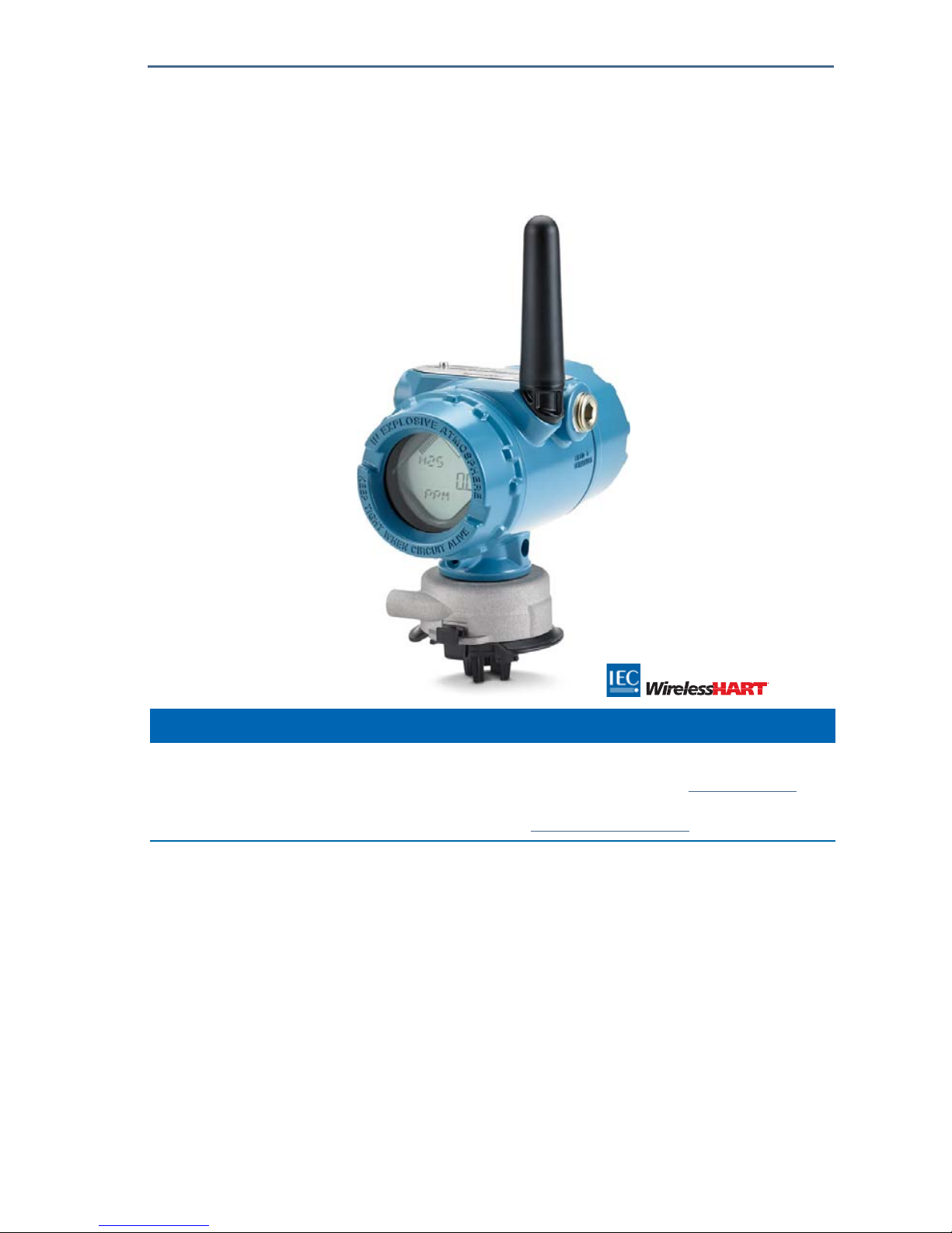
Rosemount™ 928 Wireless Gas Monitor
Integrated Wireless Gas Monitoring
NOTICE
This guide provides configuration and basic installation information for the RosemountTM 928 Wireless Gas
Monitor. It does not provide diagnostic, maintenance, service, troubleshooting, Intrinsically Safe (I.S.)
installation, or ordering information. Refer to the Rosemount 928 Wireless Gas Monitor
Reference Manual for
more information.
The manual and this guide are also available electronically on
Emerson.com/Rosemount.

August 2018
2
Quick Start Guide
Read this manual before working with the product. For personal and system safety, and for optimum product
performance, make sure to thoroughly understand the contents before installing, using, or maintaining this
product.
The United States has two toll-free assistance numbers and one international number.
Customer Central
1 800 999 9307 (7:00 a.m. to 7:00 p.m. CST)
National Response Center
1 800 654 7768 (24 hours a day)
Equipment service needs
International
1 952 906 8888
The products described in this document are NOT designed for nuclear-qualified applications.
Using non-nuclear qualified products in applications that require nuclear-qualified hardware or products may
cause inaccurate readings.
For information on Rosemount nuclear-qualified products, contact an Emerson
™
Sales Representative.
The Rosemount 928 Wireless Gas Monitor and all other wireless devices should be installed only after the
Wireless Gateway has been installed and is functioning properly. Wireless devices should also be powered up in
order of proximity from the Wireless Gateway, beginning with the closest. This will result in a simpler and faster
network installation.
Shipping considerations for wireless products
The unit was shipped to you without the power module installed. Remove the power module prior to shipping.
Each power module contains two “C” size primary lithium batteries. Primary lithium batteries are regulated in
transportation by the U. S. Department of Transportation, and are also covered by IATA (International Air
Transport Association), ICAO (International Civil Aviation Organization), and ARD (European Ground
Transportation of Dangerous Goods). It is the responsibility of the shipper to ensure compliance with these or
any other local requirements. Consult current regulations and requirements before shipping.
The power module with the wireless unit contains two “C” size primary lithium/thionyl chloride batteries. Each
battery contains approximately 2.5 grams of lithium, for a total of 5 grams in each pack. Under normal
conditions, the battery materials are self-contained and are not reactive as long as the batteries and the pack
integrity are maintained. Care should be taken to prevent thermal, electrical, or mechanical damage. Contacts
should be protected to prevent premature discharge.
Battery hazards remain when cells are discharged.
Power modules should be stored in a clean and dry area. For maximum power module life, storage temperature
should not exceed 86 °F (30 °C).
The power module has surface resistivity greater than one Gigaohm and must be properly installed in the
wireless device enclosure. Care must be taken during transportation to and from the point of installation to
prevent electrostatic charge buildup.

Quick Start Guide
3
August 2018
Failure to follow these installation guidelines could result in death or serious injury:
Ensure that only qualified personnel perform the installation.
Installation of this transmitter in an explosive environment must be in accordance with the appropriate
local, national, and international standards, codes, and practices.
Explosions could result in death or serious injury.
Before connecting a handheld communication device in an explosive atmosphere, make sure that the
instruments are installed in accordance with Intrinsically Safe or non-incendive field wiring practices.
Verify that the operating atmosphere of the transmitter is consistent with the appropriate hazardous
locations certifications.
When connecting an external device to the Rosemount 928 Wireless Gas Monitor’s discrete output in a
hazardous area, ensure that the external device is installed in accordance with Intrinsically Safe or
non-incendive field wiring practices.
Electrical shock could cause death or serious injury.
Use extreme caution when making contact with the leads and terminals.
This device complies with Part 15 of the FCC Rules. Operation is subject to the following conditions: This
device may not cause harmful interference. This device must accept any interference received, including
interference that may cause undesired operation.
This device must be installed to ensure a minimum antenna separation distance of 7.9 in. (20 cm) from all
persons.
Replace the power module as soon as possible after receiving a low battery warning. If this is not done
promptly, the device will cease to function.
The power module may be replaced in a hazardous area. The power module has a surface resistivity greater
than 1 Gigaohm and must be properly installed in the wireless device enclosure. Care must be taken during
transportation to and from the point of installation to prevent electrostatic charge buildup.
The surface resistivity of the antenna is greater than 1 Gigaohm. To avoid electrostatic charge buildup, do
not rub or clean the antenna with solvents or a dry cloth.
Substitution of components may impair intrinsic safety.
Contents
Overview . . . . . . . . . . . . . . . . . . . . . . . . . . . . . . . . 4
Installing the gas sensor module . . . . . . . . . . . 5
Installing the power module . . . . . . . . . . . . . . . 6
Bench configuration . . . . . . . . . . . . . . . . . . . . . . 7
Guided setup . . . . . . . . . . . . . . . . . . . . . . . . . . . . 9
Calibrating the gas sensor module . . . . . . . . . 32
Manual setup . . . . . . . . . . . . . . . . . . . . . . . . . . . 51
Wireless considerations . . . . . . . . . . . . . . . . . . . . 65
Electrical . . . . . . . . . . . . . . . . . . . . . . . . . . . . . . . . . 67
Verifying operating atmosphere . . . . . . . . . . . . 68
Installing the Rosemount™ 928 Transmitter . . 68
Verifying wireless network communication . . . 71
Verifying operation . . . . . . . . . . . . . . . . . . . . . . . . 75
Product certifications . . . . . . . . . . . . . . . . . . . . . . 80

August 2018
4
Quick Start Guide
1.0 Overview
The Rosemount™ 928 Wireless Gas Monitor is used with the Rosemount 628
Series of Sensor Modules. The sensor module fits integrally into the Rosemount
928 Wireless Gas Monitor Transmitter housing without the use of tools (see
Figure 2). Electrical connections are made when the sensor module is fully
seated in the Rosemount 928 Transmitter sensor module housing.
Note
Use Rosemount 628 Series Gas Sensor Modules only with the Rosemount 928 Transmitter.
Figure 1. IP Filter
A. IP Filter Housing
B. IP Filter Gasket
C. Filter Media
The Ingress Protection (IP) filter must be installed.
Do not operated the Rosemount 928 Wireless Gas Monitor without the correct IP filter installed in the
Rosemount 628 Series Gas Sensor Module. If the IP filter is not installed, damage may occur to the sensor inside
the Rosemount 628 Series Gas Sensor Module.
When installing the IP filter, verify that the IP filter gasket is in place, is properly aligned, and that it does
not block the white filter media. Refer to Figure 1 on page 4.
When handling the IP filter, avoid contact with the filter media.
Verify that all three legs are fully latched by pushing upward on each leg of the IP filter.
Avoid getting water inside the IP filter.
Do not attempt to clean the IP filter.
Do not rinse or spray the IP filter with water.
Do not immerse the IP filter in water.

Quick Start Guide
5
August 2018
2.0 Installing the gas sensor module
The Rosemount™ 628 Gas Sensor Module is held in place using a tight-fitting
seal and snap connections. The Rosemount 628 Series Gas Sensor Module is
connected to the Rosemount 928 Transmitter by two latching tabs that fit into
the bottom portion of the housing as shown in the following figure. The seal
between the transmitter housing and the Sensor Module assembly is designed
so that a snug, airtight fit is achieved between the two assemblies when
properly installed.
1. Remove the Rosemount 628 Gas Sensor Module from its packaging.
2. If installing a Rosemount 628 Gas Sensor Module on the Rosemount 928
Transmitter for the first time, remove the protective plastic cap from the
sensor module housing.
3. The Rosemount 628 Gas Sensor Module contains a keying feature that
ensures that the module cannot be forced into the transmitter housing in an
incorrect alignment. Confirm that the keying feature is aligned by rotating it
into position before installing the Rosemount 628 Gas Sensor Module into
the Rosemount 928 Transmitter.
4. Slide the sensor module assembly up into the main Rosemount 928
Transmitter housing until it is completely seated.
Figure 2. Inserting the Rosemount 628 Gas Sensor Module into the Rosemount 928
Transmitter
A. Rosemount 928 Transmitter housing
B. Rosemount 628 Gas Sensor Module
C. Latching tabs
5. To ensure a firm latch and seal, push the Rosemount 628 Gas Sensor Module
upward until the two latching tabs are fully engaged. Push up on the bottoms
of the latching tabs after they are seated.

August 2018
6
Quick Start Guide
6. Allow the Rosemount 928 Wireless Gas Monitor to warm up before
continuing. Refer to the following table for maximum warm up times based
on gas type. During the warm up period, the displayed values, alerts, and gas
concentrations will not reflect actual measurements; readings will not be
transmitted.
To remove the Rosemount 628 Gas Sensor Module, compress the two latching
tabs and pull downward until the module is released from the Rosemount 928
Transmitter housing.
3.0 Installing the power module
To perform configuration, the Rosemount™ 628 Gas Sensor Module must be
installed in a functional Rosemount 928 Transmitter. The Rosemount 928
Wireless Gas Monitor is powered by the Emerson
™
701 SmartPower™ Module–
Black.
1. Remove the rear housing cover.
A. Rear Housing Cover
Gas type Maximum warm up period
Hydrogen Sulfide (H2S) One minute

Quick Start Guide
7
August 2018
2. Connect the Emerson 701 SmartPower Module–Black.
3. Verify the connection by viewing the LCD display.
4. Replace the rear housing cover and completely tighten.
5. Allow the Rosemount 928 Wireless Gas Monitor to warm up before
continuing. Refer to the following table for maximum warm up times based
on gas type. During the warm up period, the displayed values, alerts, and gas
concentrations will not reflect actual measurements; readings will not be
transmitted.
4.0 Bench configuration
The Rosemount™ 928 Wireless Gas Monitor will receive any HART®
communication from a handheld Field Communicator or from AMS Wireless
Configurator. Remove the rear housing cover to expose the terminal block and
HART communication terminals, then connect the power module to power the
device for configuration.
4.1 Field Communicator bench configuration
A Rosemount 928 Transmitter Device Description (DD) is required for HART®
communication. To connect to the Rosemount 928 Wireless Gas Monitor using
Field Communicator, refer to “Guided setup” on page 9. To obtain the latest DD,
go to
Emerson.com/Device Install Kits and then visit the Emerson Web page for
your handheld device.
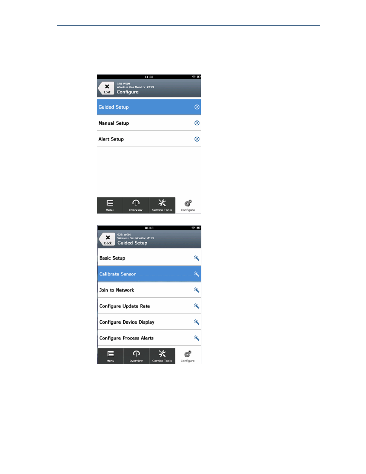
1. On the Home screen, select Configure.
Gas type Maximum warm up period
Hydrogen Sulfide (H2S) One minute

August 2018
8
Quick Start Guide
2. Do one of the following:
On the Configure screen, select Guided Setup to verify or change initial
configuration settings. Refer to “Guided setup” on page 9. Refer to the
Field Communicator subsections for each configuration task.
On the Configure screen, select Manual Setup to verify or change all
configuration settings, including optional, advanced settings. Refer to
“Manual setup” on page 51. Refer to the Field Communicator subsections
for each configuration task.
3. When finished, select Send to implement configuration changes.
4. When configuration is completed, remove the HART communication leads
from the COMM terminals on the terminal block and replace the rear housing
cover.
4.2 AMS Wireless Configurator bench configuration
AMS Wireless Configurator is capable of connecting to devices directly, using a
HART
®
modem, or through a Wireless Gateway.
1. In the AMS Device Explorer pane, select the HART Modem 1.
2. In the device pane, double-click the device icon.
3. Select Configure.

Quick Start Guide
9
August 2018
4. In the Configure pane, do one of the following:
Select Guided Setup to verify or change initial configuration settings.
Refer to “Guided setup” on page 9. Refer to the AMS Wireless
Configurator subsections for each configuration task.
Select Manual Setup to verify or change all configuration settings,
including optional, advanced settings. Refer to “Manual setup” on
page 51. Refer to the AMS Wireless Configurator subsections for each
configuration task.
5. When finished, select Send to implement configuration changes.
5.0 Guided setup
Note
The Field Communicator Guided Setup configuration procedures in this quick start guide
were developed using Emerson™ AMS Trex™ Device Communicator. The menus are
identical to those found in other Field Communicators, but are navigated using touch
screens rather than fast keys. Refer to the manual for your handheld communicator device
for more information.
1 Remove the rear housing.
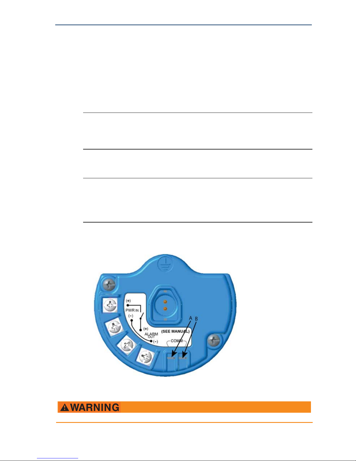
2. Connect the HART
®
communication leads to the HART terminals on the
handheld communicator.
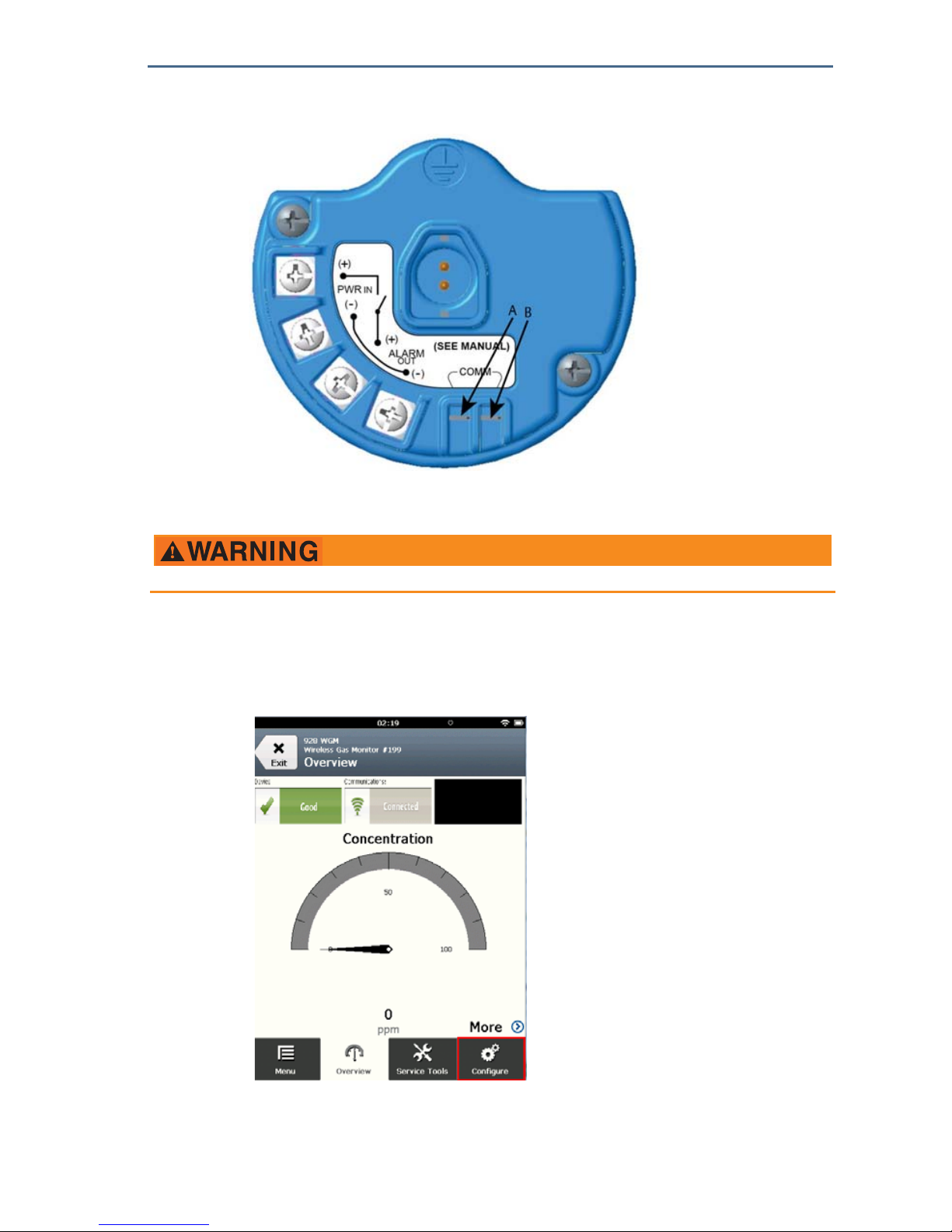
3. Connect the HART communication leads to the COMM terminals on the
Rosemount 928 Transmitter terminal block (A and B).
A. +Comm Terminal
B. -Comm Terminal
Do not connect to the COMM terminals when an explosive atmosphere is present.

August 2018
10
Quick Start Guide
4. Start your handheld communicator device. If necessary, open HART Field
Communicator on your handheld device to establish HART communication.
Refer to the manual for your handheld communicator device for more
information.
5. On the Overview screen, select Configure.
6. On the Configure screen, select Guided Setup.
7. Perform each of the configuration tasks in the following subsections.

Quick Start Guide
11
August 2018
5.1 Basic setup
Basic setup using Field Communicator
1. On the Guided Setup screen, select Basic Setup.
2. On the Device Information screen, select any of the following and configure
as needed. Otherwise, continue with Step 3.

August 2018
12
Quick Start Guide
Long Tag: Enter an identifier for the device up to 32 characters long using
the virtual keypad. The Long Tag is blank by default and does not display if
left blank.
Tag: Enter an identifier for the device up to eight uppercase alphabetic
and numeric characters long using the virtual keypad. The Tag is blank by
default and does not display if left blank.

Quick Start Guide
13
August 2018
Descriptor: Enter a description of the device up to 16 alphabetic,
numeric, and special characters long. The Descriptor is blank by default
and does not display if left blank.
Message: Enter a message up to 32 alphabetic, numeric, and special
characters long. The Message is blank by default, does not display if left
blank, and may be used for any purpose.

August 2018
14
Quick Start Guide
3. On the Device Information screen, select Next.
4. On the Configure Sensor screen, select OK to confirm successful sensor
configuration.

Quick Start Guide
15
August 2018
Basic setup using AMS Wireless Configurator
1. On the Guided Setup tab, in the Initial Setup area, select Basic Setup.
2. On the Device Information tab, you have the option to configure any of the
following as needed. Otherwise, continue with Step 3.
Long Tag: Enter an identifier for the device up to 32 characters long using
the virtual keypad. The Long Tag is blank by default and does not display if
left blank.
Tag: Enter an identifier for the device up to eight uppercase alphabetic
and numeric characters long using the virtual keypad. The Tag is blank by
default and does not display if left blank.
Descriptor: Enter a description of the device up to 16 alphabetic,
numeric, and special characters long. The Descriptor is blank by default
and does not display if left blank.

August 2018
16
Quick Start Guide
Message: Enter a message up to 32 alphabetic, numeric, and special
characters long. The Message is blank by default, does not display if left
blank, and may be used for any purpose.
3. On the Basic Setup screen, select Next.
4. Select Finish.
5.2 Joining the Rosemount 928 Transmitter to a wireless
network
To communicate with the Wireless Gateway and the host system, the
Rosemount 928 Transmitter must be configured to communicate using the
wireless network.
This procedure is the wireless equivalent of connecting wires from a transmitter
to the host system. Using Field Communicator or AMS Wireless Configurator,
enter the Network ID and Join Key so that they match the Network ID and Join

Quick Start Guide
17
August 2018
Key of the Wireless Gateway and other devices in the network. If the Network ID
and Join Key are not identical, the Rosemount 928 Transmitter will not
communicate with the network. The Network ID and Join Key may be obtained
from the Wireless Gateway on the Setup>Network >Settings page on the web
server.
Note
The amount of time required to join the new device or devices to the network is
dependent upon the number of devices being joined and the number of devices in the
current network. One new device joining an existing network with multiple devices may
take up to five minutes. Multiple new devices joining an existing network may take up to
60 minutes.
Joining a wireless network using Field Communicator
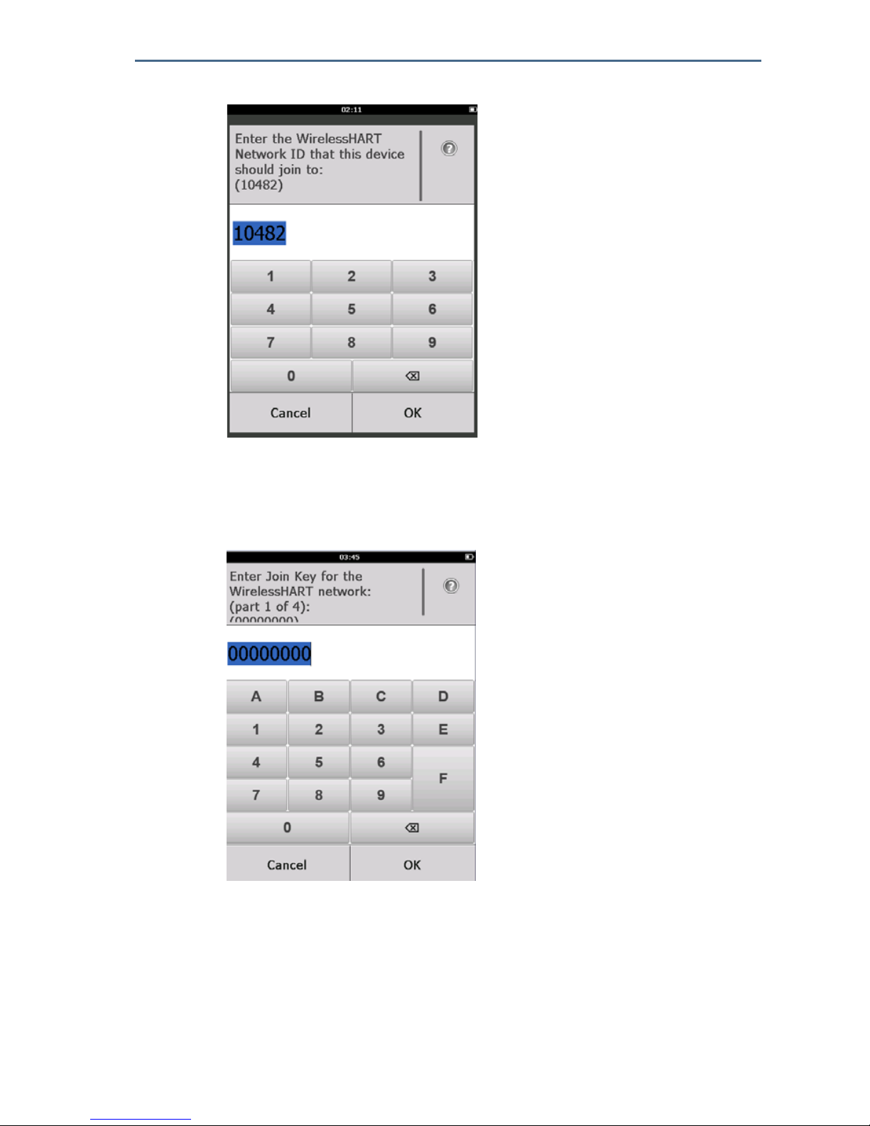
1. On the Guided Setup screen, select Join to Network.
2. On the Join to Network screen, use the numeric keypad to enter the
WirelessHART
®
Network ID. The Network ID must match the Wireless
Gateway Network ID. Refer to the System Settings> Network > Network
Settings page in the Wireless Gateway web-based user interface for the
Network ID.
August 2018
18
Quick Start Guide
3. Select OK.
4. On the Join Key screen, use the hexadecimal keypad to enter the first part of
the Join Key. The Join Key must match the Wireless Gateway Join Key. Refer to
the System Settings > Network > Network Settings page in the Wireless
Gateway web-based user interface for the Join Key.
5. Select OK.
6. Repeat steps 4–5 to configure the remaining keys to join the Wireless
Gateway.
Joining a wireless network using AMS Wireless Configurator
1. On the Guided Setup tab, in the Wireless area, select Join Device to
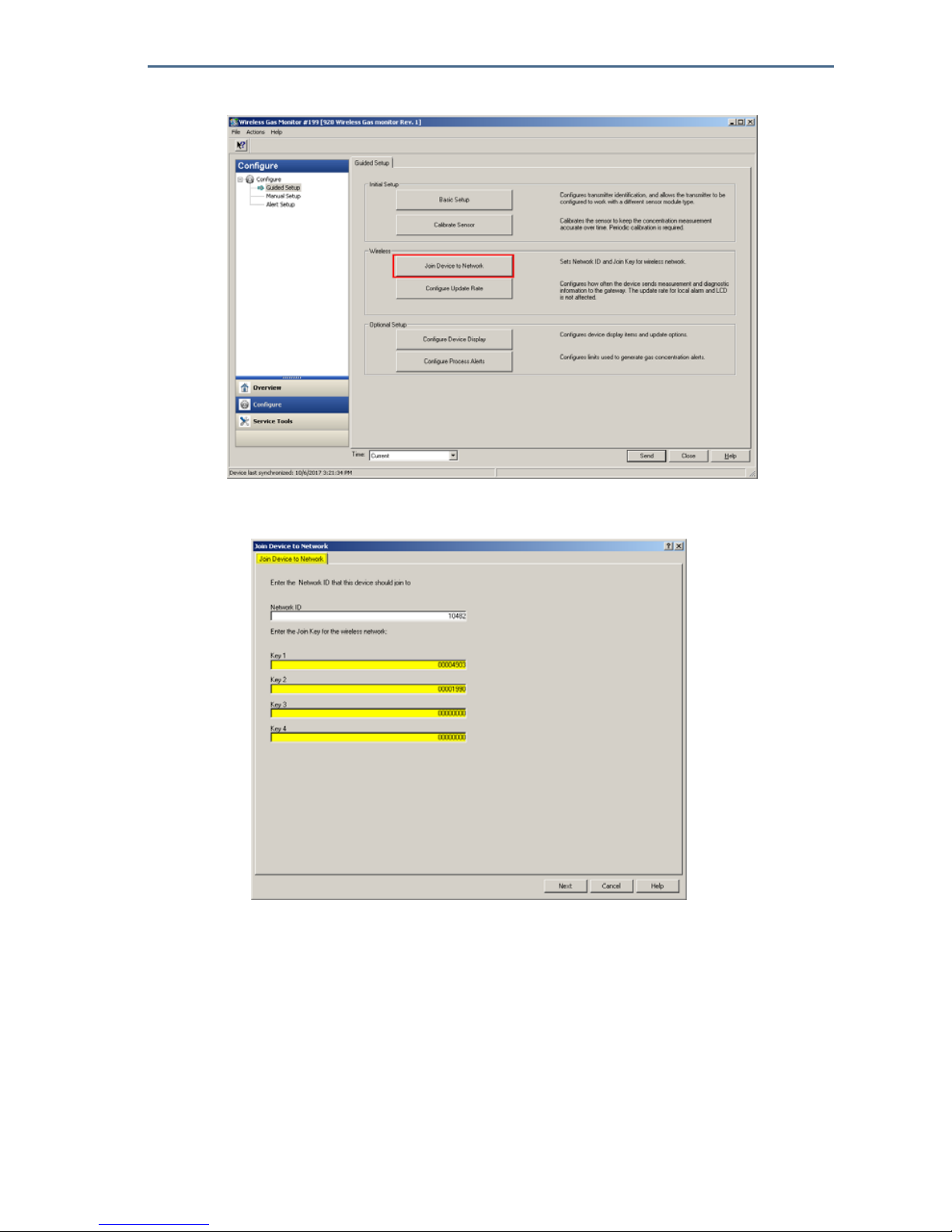
Quick Start Guide
19
August 2018
Network.
2. On the Join Device to Network tab, enter the Network ID and Join Key.
3. Select Next.
4. Follow the steps in the wizard to complete the network configuration.
5.3 Update rate considerations
Before configuring the wireless update rate for your wireless devices, evaluating
the safety concerns, conditions and wireless network in your facility will guide
you toward selecting the correct update rate to meet your needs.
Consider the potential for toxic gas release, the severity of the potential gas
concentration that may be released, and whether the device is located in a
populated area when specifying the update rate. The default update rate is eight
seconds and will be appropriate for most applications. A more frequent update
August 2018
20
Quick Start Guide
rate may be used if desired. A less frequent update rate will extend transmitter
power module life and optimize Wireless Gateway device capacity.
Consider the speed with which you want to be alerted to a dangerous
concentration of toxic gas. “Reporting by exception” is not recommended for
the Rosemount 928 Wireless Gas Monitors or Emerson Wireless Gateways due
to its potential adverse effect on Wireless Gateway capacity and network
integrity. Therefore, select an update rate for all Wireless Gas Monitors that
corresponds to the safety needs of your facility but does not exceed the capacity
of the Wireless Gateway or your wireless network.
Note
The LCD display and the optional local alarm output (if installed) update rates are not
affected by the configured wireless update rate.
5.4 Configuring the update rate
The Rosemount™ 928 Wireless Gas Monitor takes measurements every two
seconds. The update rate is the frequency at which new measurements and
device status are transmitted over the wireless network. The update rate may be
changed during configuration. The update rate range is 1 second to 60 minutes.
The default update rate is eight seconds. Less frequent update rates help extend
power module life and optimize Wireless Gateway capacity.
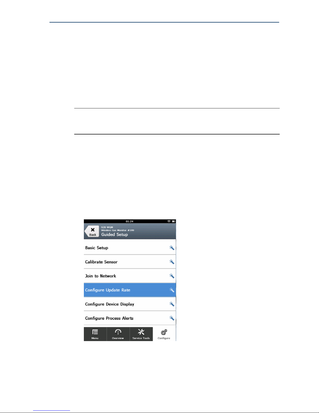
Configuring the update rate using Field Communicator
1. On the Guided Setup screen, select Configure Update Rate.
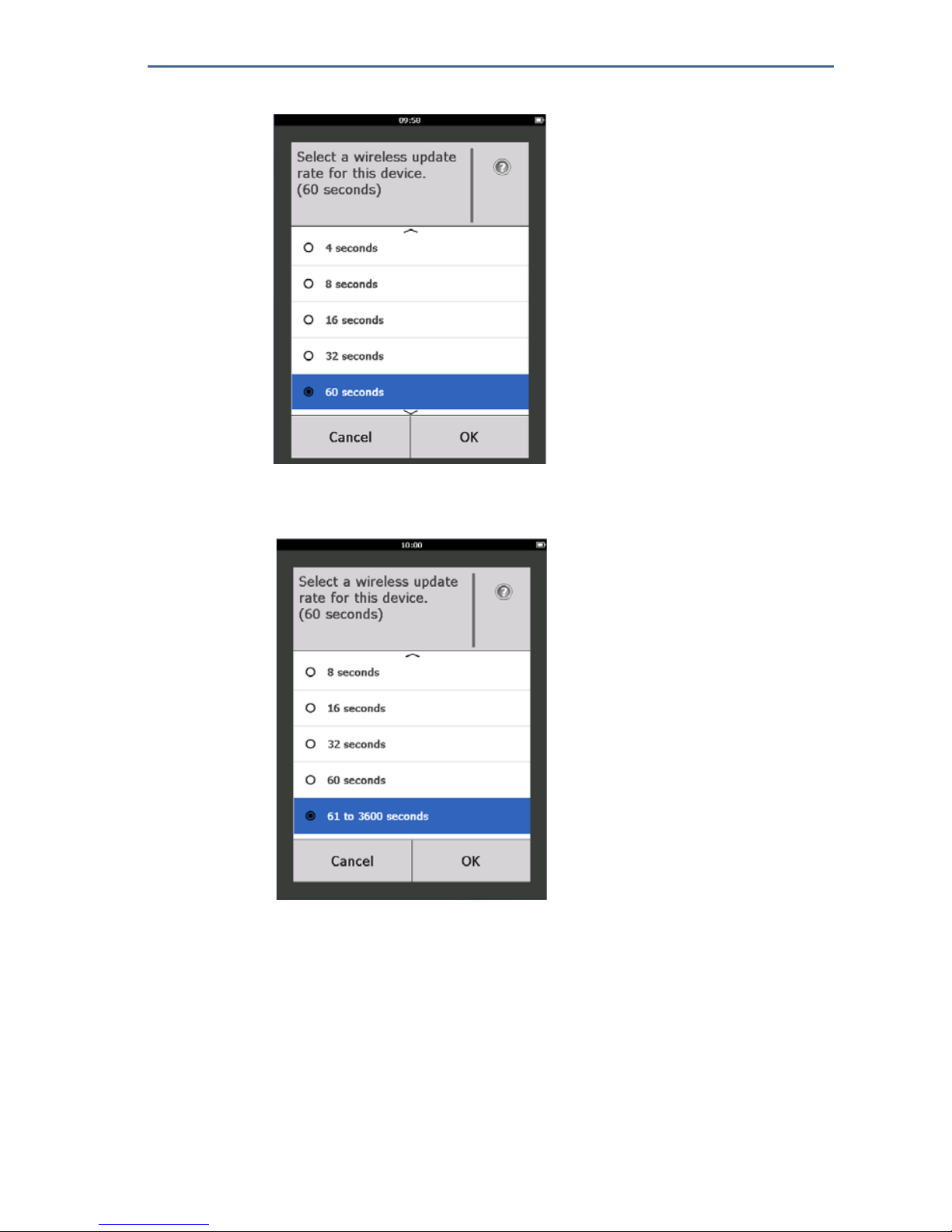
2. On the Configure Update Rate screen, do one of the following:
a. For an update rate from 1 second to 60 seconds, select an update rate
from the list.
Quick Start Guide
21
August 2018
b. Select OK.
—Or—
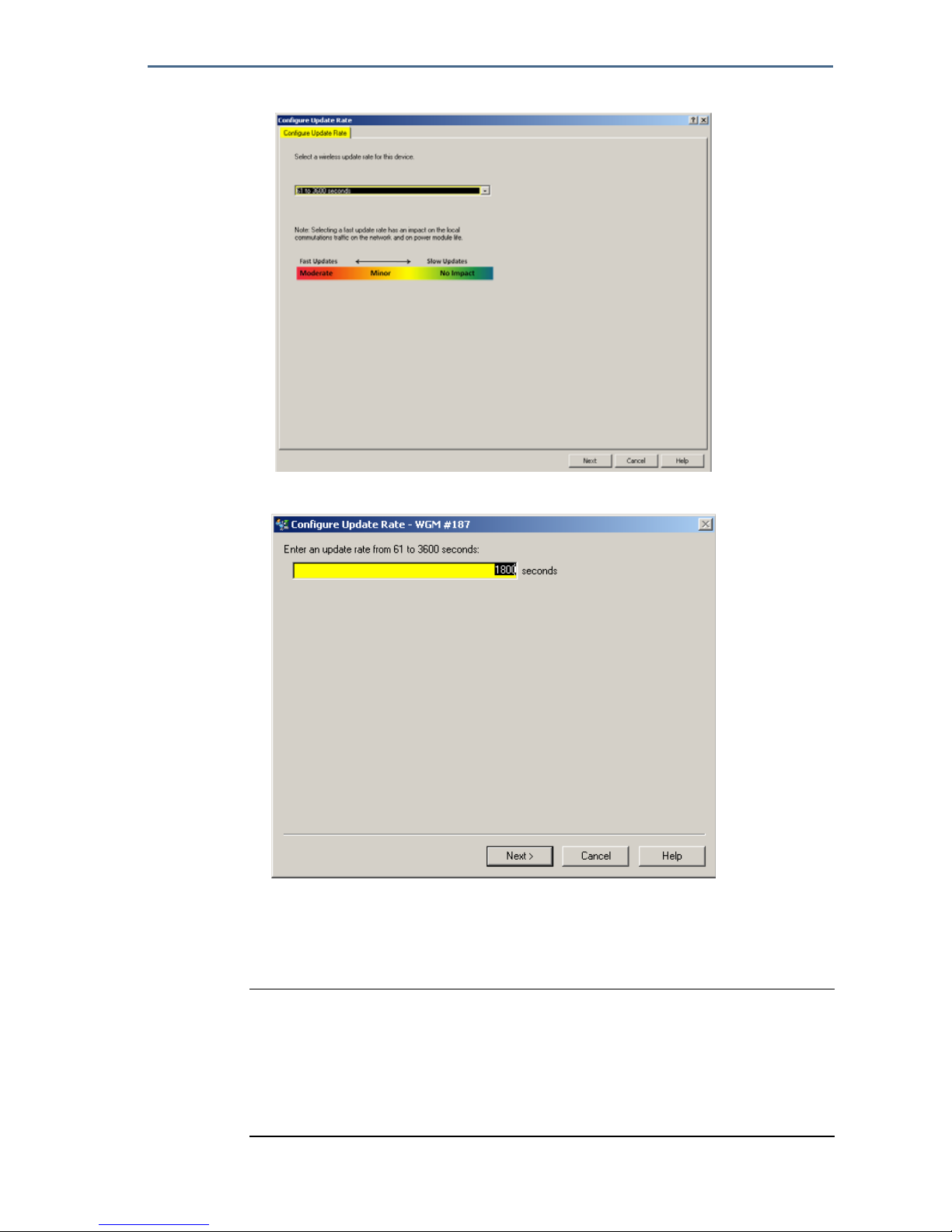
a. For update rates greater than 60 seconds, select 61-3600 seconds from
the list.
b. Enter the update rate in number of seconds. For example, enter 1800
seconds for 30 minutes.

August 2018
22
Quick Start Guide
c. Select OK.
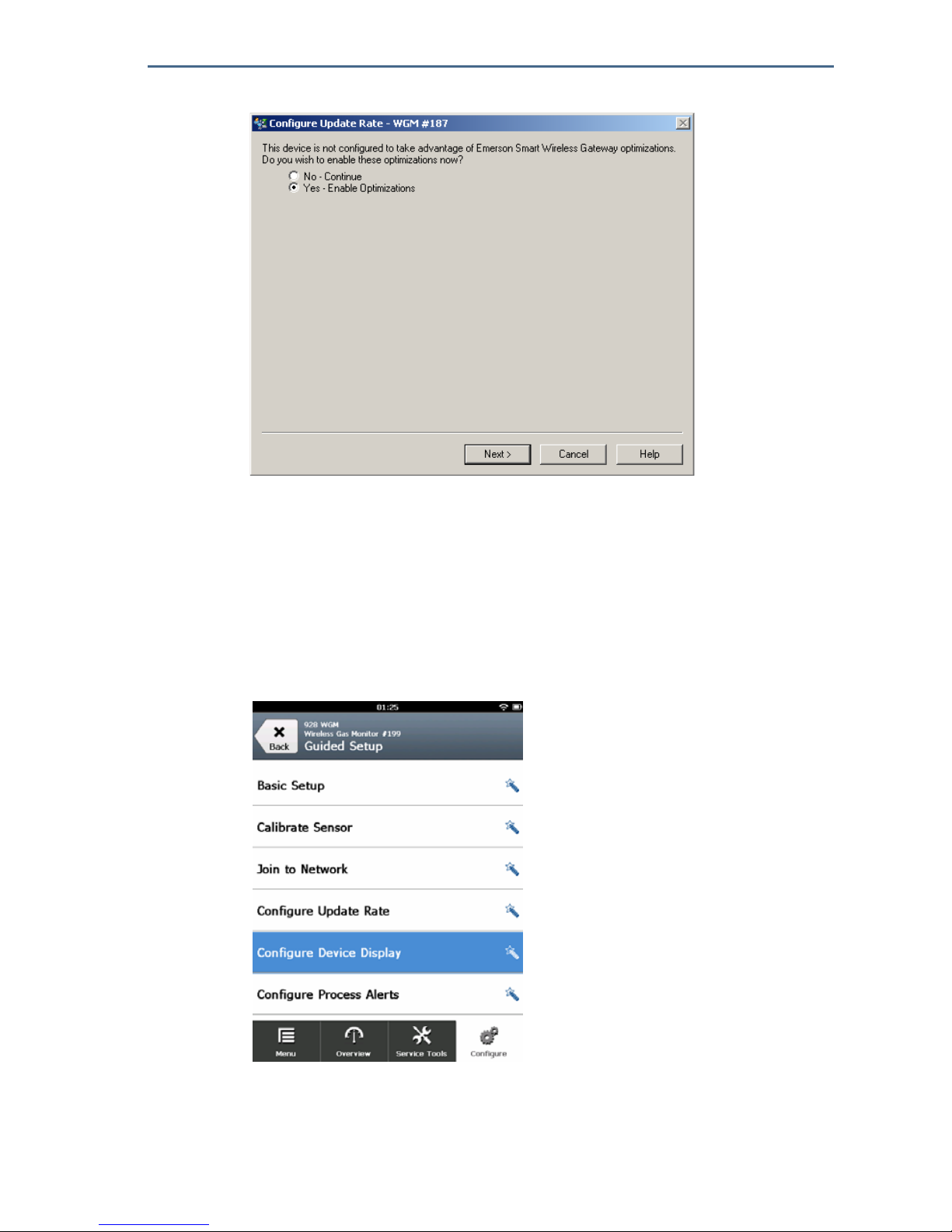
3. On the Emerson Wireless Gateway Optimizations screen, select Yes-Enable
Optimizations to save and use wireless optimizations or select No-Disable
Optimizations to reject wireless optimizations.
Note
Wireless Gateway optimizations combine process measurement and device
diagnostic messages from field devices to the Wireless Gateway, saving
network bandwidth. If optimizations are not used, more message packets
are required to receive the same amount of information. Enabling Wireless
Gateway optimizations is recommended.
4. Select OK.

Quick Start Guide
23
August 2018
5. On the Configure Update Rate screen, select OK to confirm successful
update rate configuration.
Configuring the update rate using AMS Wireless Configurator
1. On the Guided Setup tab, in the Wireless area, select Configure Update Rate
to configure the frequency at which the device reports measurement and
diagnostic information.
2. On the Configure Update Rate screen, do one of the following:
a. Select an update rate from 1 second to 60 seconds from the list.
b. Select Next.
—Or—
August 2018
24
Quick Start Guide
a. Select 61–3600 from the list.
b. Type the number of seconds for an update rate from 61 seconds to 60
minutes. For example, 1800 seconds for 30 minutes.
c. Select Next.
3. On the Wireless Gateway Optimizations screen, select Yes-Enable
Optimizations to save and use wireless optimizations or select No-Disable
Optimizations to reject wireless optimizations.
Note
Wireless Gateway optimizations combine process measurement and device
diagnostic messages from field devices to the Wireless Gateway, saving
network bandwidth. If optimizations are not used, more message packets
are required to receive the same amount of information. Enabling Wireless
Gateway optimizations is recommended.
Quick Start Guide
25
August 2018
4. Select Next.
5. Select Next and then select Finish to save the update rate configuration.
5.5 Configuring device display mode
The device display mode defines whether or how frequently the device LCD
display is turned on to display selected dynamic variable screens. Disabling the
display mode or selecting a less frequent display mode will extend power
module life.
Configuring device display mode using Field Communicator
1. On the Guided Setup screen, select Configure Device Display.

August 2018
26
Quick Start Guide
2. On the Device Display Option screen select one of the following display
mode options:
Disabled: The display is turned off. This is useful if the display will never
be viewed locally.
On Demand: The display is on when the Rosemount 928 Wireless Gas
Monitor is connected to a handheld communication device or when it
receives a signal from its Wireless Gateway.
Periodic: The display is on only during updates at the configured update
rate.
High Availability: The display is always on regardless of the configured
update rate. This is the default display mode option.
3. Select OK to save the selected device display option.
Note
When a handheld communication device is connected to the Rosemount 928 Wireless Gas
Monitor, the LCD display is in High Availability mode. Selecting and accepting the On
Demand or Periodic options does not take effect until approximately five minutes after
the handheld communicator device is disconnected. Selecting and accepting Disabled
takes effect immediately.

Quick Start Guide
27
August 2018
Configuring device display mode using AMS Wireless Configurator
1. On the Guided Setup tab, in the Optional Setup area, select Configure
Device Display.
2. Select one of the following display mode options:
Disabled: The display is turned off. This is useful if the display will never
be viewed locally.
On Demand: The display is on when the Rosemount
™
928 Wireless Gas
Monitor is connected to a handheld communication device or when it
receives a signal from its Wireless Gateway.
Periodic: The display is on only during updates at the configured update
rate.
High Availability: The display is always on regardless of the configured
update rate. This is the default display mode option.
3. Follow the steps in the wizard to configure the device display mode.
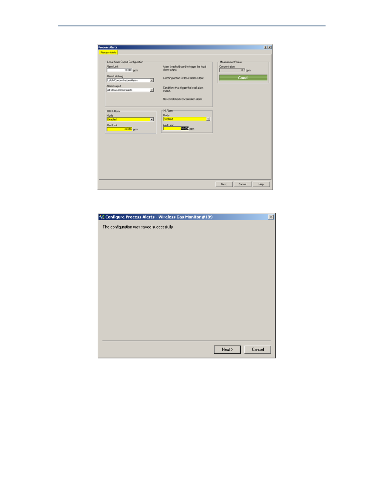
5.6 Configuring process alerts
Process alerts allow the user to configure the Rosemount ™928 Wireless Gas
Monitor to send a HART
®
message when the configured data point is exceeded.
Alarms remain active if the set points are exceeded and the alert mode is ON.
Process alerts are displayed on a handheld communication device, on the AMS
Device Manager Status screen, on the Wireless Gateway web interface, on host
systems with which the Wireless Gateway communicates, and in the error
section of the LCD display (if so configured).
The Gas Concentration alarm may be latched. If Latch Concentration Alarms is
selected, the alarm output is latched until the alert is manually cleared. A
latched gas concentration alarm may be manually reset by removing and
reinstalling the power module. Refer to the “Removing the power module”
section in the Rosemount 928 Wireless Gas Monitor
Reference Manual and
“Installing the power module” on page 6. Latched alarms do not remain latched
following a device reset or power module failure.

August 2018
28
Quick Start Guide
Latched alarms may be cleared by resetting the alarm using Field
Communicator or AMS Wireless Configurator. Refer to the “Clearing latched
alarms” section in the Rosemount 928 Wireless Gas Monitor
Reference Manual
for information about clearing latched local alarms. If Not Latched is selected,
the gas concentration alarm clears automatically when the gas concentration
level dissipates below the specified High Concentration Threshold.
Clearing alert history clears process alert history for other alarms, but does not
clear latched gas concentration alarms. Refer to the “Clearing process alarm
history” section in the Rosemount 928 Wireless Gas Monitor
Reference Manual.
Alert history for other process alerts may be queried to determine whether they
have been active.
Configuring process alerts using Field Communicator
1. On the Guided Setup screen, select Configure Process Alerts.
2. On the Process Alerts screen, select a process alert to configure.

Quick Start Guide
29
August 2018
3. On the selected Process Alert screen, select Mode.
4. On the Mode screen, select Enabled.
5. Select OK.
6. On the Alert Limit screen, use the numeric keypad to enter an alarm set point
limit for the selected process alert based on operations best practices and in
compliance with all local regulations.

August 2018
30
Quick Start Guide
7. Select OK.
8. Select OK.
9. On the selected Process Alert screen, select Next.
Quick Start Guide
31
August 2018
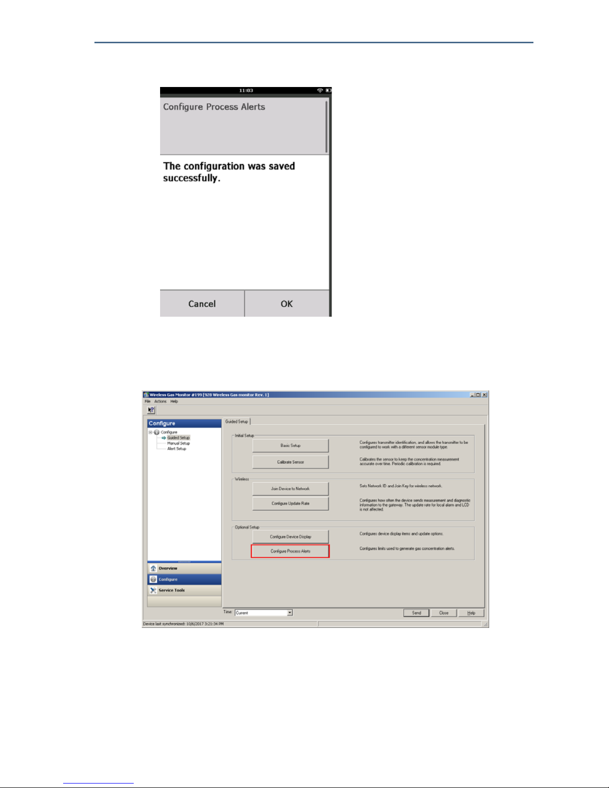
10.On the Configure Process Alarms screen, select OK to confirm successful
process alarm configuration.
11.Repeat steps 2–10 as necessary to configure additional process alarms.
Configuring process alarms using AMS Wireless Configurator
1. On the Guided Setup tab, in the Optional Setup area, select Configure
Process Alerts.
2. In the Mode list, select Enabled to enable the alarm.
3. In the Alert Limit box, enter an alert limit for the selected process alert based
on your needs and local regulations.
August 2018
32
Quick Start Guide
4. Repeat steps 2–3 if necessary to configure the HI Alarm process alert.
5. Select Next.
6. Select Next to confirm successful process alert configuration.
7. Select Finish.
6.0 Calibrating the gas sensor module
Calibrating the Rosemount™ 628 Gas Sensor Module ensures that the analog,
digital, and discrete outputs accurately transmit the target gas concentrations
registered by the Rosemount 628 Gas Sensor Module. Although calibration was
performed at the factory, the device must be calibrated at the following times
to ensure accurate and correct operation:
During installation
Quick Start Guide
33
August 2018
At least every 90 days throughout the device’s service life
When replacing the Rosemount 628 Gas Sensor Module
The Rosemount 628 Gas Sensor Module is a smart sensor. As such, it retains its
own calibration information. It must be connected to a Rosemount 928
Transmitter to perform calibration, but the calibration settings are stored in the
sensor itself rather than in the Rosemount 928 Transmitter. The Rosemount 628
Gas Sensor Module may be uninstalled from a Rosemount 928 Transmitter and
reinstalled in another without affecting its calibration.
Note
A conventional calibration cup is not required to calibrate the Rosemount 628 Gas Sensor
Module. Connect calibration tubing (PVC tubing, 3/16-in. ID, 5/16-in. OD) directly to the
fitting on the Rosemount 628 Gas Sensor Module IP filter assembly (00628-9000-0001).
6.1 Calibrating using Field Communicator
Note
The Field Communicator Guided Setup configuration procedures were developed using
Emerson™ AMS Trex Device Communicator. The menus are identical to those found in
other Field Communicators, but are navigated using touch screens rather than fast keys.
Refer to the manual for your handheld communicator device for more information.
1 Connect the HART® communication leads from the Field Communicator
HART terminals to the COMM terminals on the terminal block of the
Rosemount
™
928 Transmitter.
A. +Comm Terminal
B. -Comm Terminal
Do not connect to the COMM terminals when an explosive atmosphere is present.
August 2018
34
Quick Start Guide
2. Establish communication between the Rosemount 928 Transmitter and the
Field Communicator.
3. On the Field Communicator Home screen, select Configure.
4. On the Configure screen, select Guided Setup.
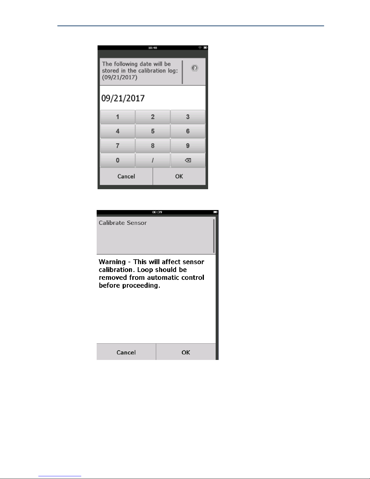
5. On the Guided Setup screen, select Calibrate Sensor.
Quick Start Guide
35
August 2018
6. Select OK to accept the current date as the calibration date and continue.
7. Acknowledge the warning. If necessary, remove the loop from automatic
control.
8. Expose the sensor to clean air to zero the reading. If the ambient air may
contain trace amounts of target gas or other gases (for example, carbon
monoxide from engine exhaust) that may interfere with zeroing the device,
do the following:
a. Obtain a cylinder of verified clean air and a length of calibration tubing
(PVC tubing,
3
/16-in. ID, 5/16-in. OD).
August 2018
36
Quick Start Guide
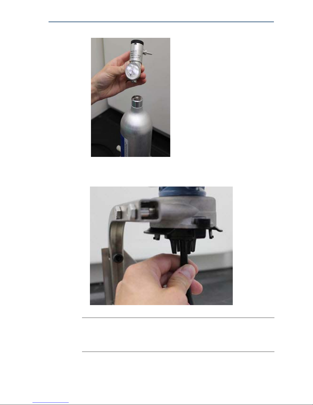
b. Install a regulator on the clean air cylinder.
c. Attach a length of calibration tubing (PVC tubing,
3
/16-in. ID, 5/16-in OD)
from the regulator on the clean air cylinder to the fitting on the
Rosemount 628 Gas Sensor Module IP filter assembly (part number
00628-9000-0001).
d. Release the clean air to the sensor.
Note
If a long length of calibration tubing is required to reach the device, make
allowances for a delay in response time from the sensor while the clean air
travels the length of the calibration tubing.
e. Perform steps 11—14.
f. Turn off the clean air when the sensor is correctly zeroed.

Quick Start Guide
37
August 2018
9. Select OK when the zero measurement reading stabilizes.
Note
Negative measurement readings may occur and are normal during zeroing.
10.Wait while Field Communicator performs zero adjustment.
11.Select OK to accept the new zero measurement.

August 2018
38
Quick Start Guide
12.Select OK to accept the new zero calibration.
13.On the Calibrate Sensor screen, enter a gas concentration level that
corresponds to the concentration of calibration gas that will be applied
during calibration. This value must be between 5 ppm and 100 ppm.
14.Select OK.
Before performing the next step, verify that the regulator is closed to avoid releasing target gas into the
air during calibration.

Quick Start Guide
39
August 2018
15.Install a regulator on the target gas source.
16.Attach a length of calibration tubing (PVC tubing, 3/16-in. ID, 5/16-in. OD) from
the regulator on the target gas source to the fitting on the Rosemount 628
Gas Sensor Module IP filter assembly (part number 00628-9000-0001).
17.Release the target gas from the target gas source. A flow rate of 1.0 liters per
minute is recommended to ensure a consistent sensor reading.
Note
If a long length of calibration tubing is required to reach the device, make
allowances for a delay in response time from the sensor while the target gas
travels the length of the calibration tubing.
August 2018
40
Quick Start Guide
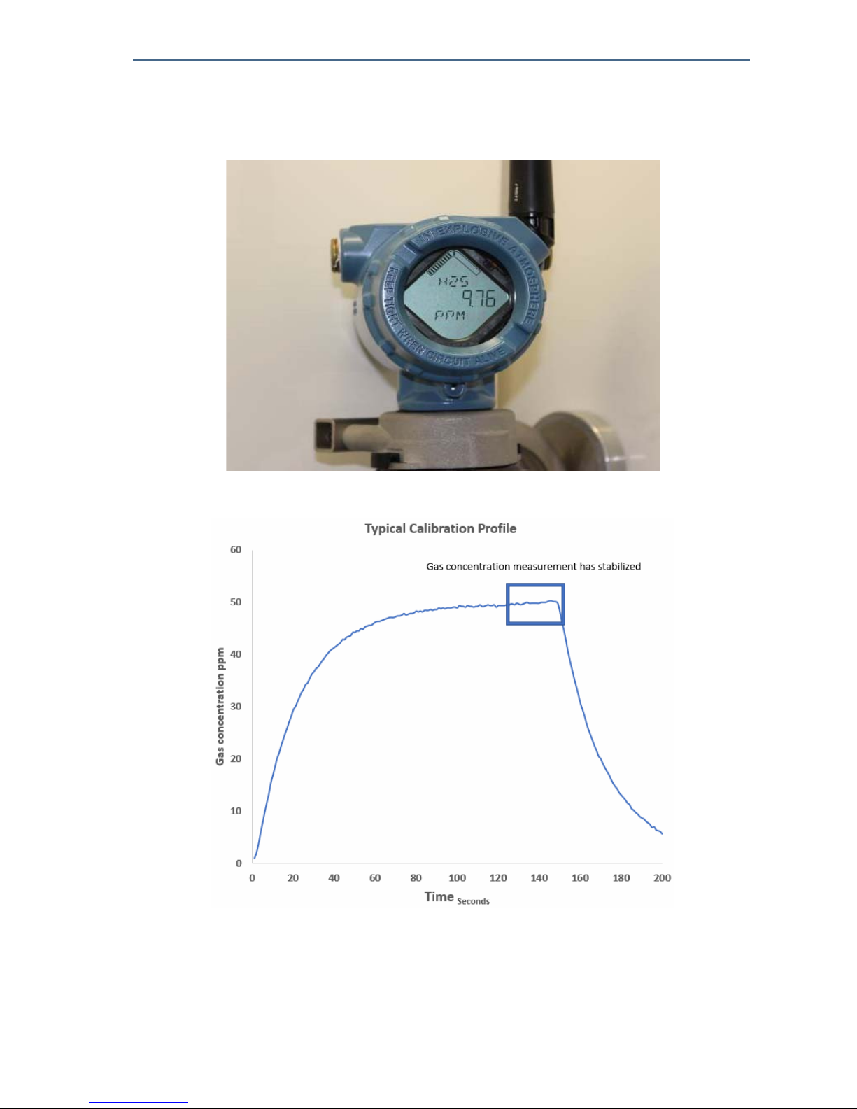
18.A gas concentration should begin to register on the LCD display and gradually
increase to the calibration gas concentration level. The gas concentration
level shown on the device display may not exactly match that shown on the
label of the target gas source.
19.Wait while the gas concentration measurement stabilizes. Refer to the
following figure.

Quick Start Guide
41
August 2018
20.Select OK when the gas concentration measurement stabilizes at or near the
target gas concentration level.
21.Wait while Field Communicator performs calibration.
22.When the calibration process finishes, the new adjusted reading is displayed.
Select OK.
Note
If unable to calibrate the sensor, verify that the correct sensor is installed,
that the correct target gas is being applied, and that the IP filter is not
clogged or obstructed. A sensor that cannot accept a new calibration may
have reached the end of its service life. Replace the Rosemount 628 Gas
Sensor Module and repeat this procedure. Refer to the “Replacing the
Rosemount 628 Gas Sensor Module” section in the Rosemount 928 Wireless
Gas Monitor Reference Manual.

August 2018
42
Quick Start Guide
23.Select Accept new calibration and then select OK.
24.The Service Reminder screen is displayed if a service reminder is configured
and enabled. Select OK to accept the service reminder date or enter another
date. Refer to the “Service reminders” section of the Rosemount 928
Wireless Gas Monitor
Reference Manual for more information.
25.Shut off the target gas flow at the regulator.
26.Detach the calibration tubing from the regulator on the target gas source
and from the IP filter inlet on the bottom of the Rosemount 628 Gas Sensor
Module.
6.2 Calibrating using AMS Wireless Configurator
1. On the Guided Setup screen, in the Initial Setup area, select Calibrate

Quick Start Guide
43
August 2018
Sensor.
2. On the Calibrate Sensor screen, select Next to accept the current date as the
calibration date and continue.

August 2018
44
Quick Start Guide
3. On the Warning screen, select Next.
4. Expose the sensor to clean air to zero the reading. If the ambient air may
contain trace amounts of target gas or other gases (for example, carbon
monoxide from engine exhaust) that may interfere with zeroing the device,
do the following:
a. Obtain a cylinder of verified clean air and a length of calibration tubing
(PVC tubing,
3
/16-in. ID, 5/16-in. OD).
b. Install a regulator on the clean air cylinder.

Quick Start Guide
45
August 2018
c. Attach a length of calibration tubing (PVC tubing, 3/16-in. ID, 5/16-in. OD)
from the regulator on the clean air cylinder to the IP filter inlet on the
bottom of the Rosemount 628 Gas Sensor Module.
d. Release the clean air to the sensor.
Note
If a long length of calibration tubing is required to reach the device, make
allowances for a delay in response time from the sensor while the clean air
travels the length of the calibration tubing.
e. Perform steps 5—7.
f. Turn off the clean air when the sensor is correctly zeroed.
5. Select Next when the zero measurement reading stabilizes.
6. Select Next.

August 2018
46
Quick Start Guide
7. Select Accept New Zero.
8. Select Next.
9. On the Calibrate Sensor screen, enter a gas concentration level that
corresponds to the concentration of calibration gas that will be applied
during calibration. This value must be between 5 ppm and 100 ppm.

Quick Start Guide
47
August 2018
10.Select Next.
11.Install a regulator on the target gas source.
Before performing the next step, verify that the regulator is closed to avoid releasing gas into the air
during calibration.

August 2018
48
Quick Start Guide
12.Attach a length of calibration tubing (PVC tubing, 3/16-in. ID, 5/16-in. OD) from
the regulator on the target gas source to the IP filter inlet on the bottom of
the Rosemount 628 Gas Sensor Module.
13.Release the target gas from the target gas source. A flow rate of 1.0 liters per
minute is recommended to ensure a consistent sensor reading.
Note
If a long length of calibration tubing is required to reach the device, make
allowances for a delay in response time from the sensor while the target gas
travels the length of the calibration tubing.
14.A gas concentration should begin to register on the device display and
gradually increase to the calibration gas concentration level. The gas
concentration level shown on the device display may not exactly match that
shown on the label attached to the target gas source.
Quick Start Guide
49
August 2018
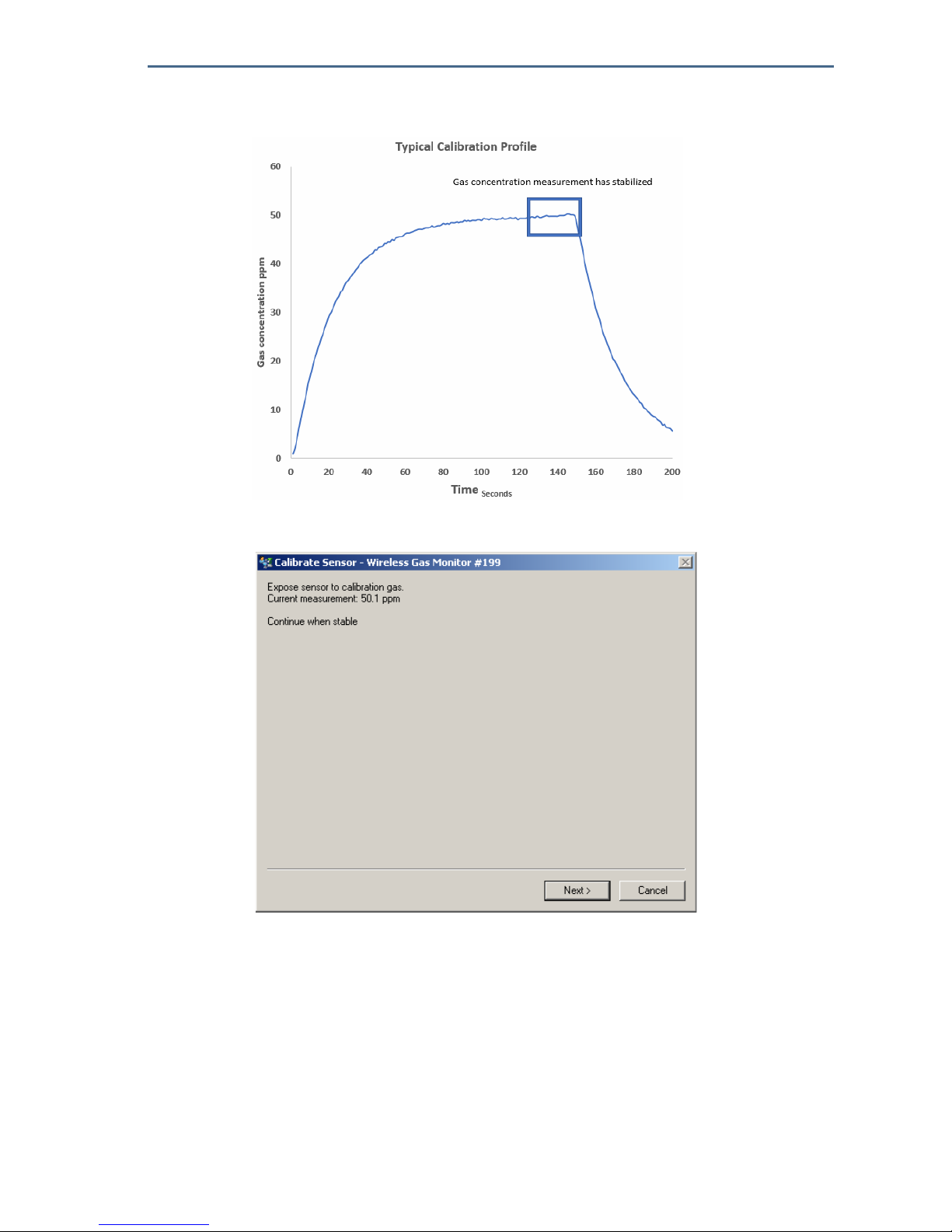
15.Wait while the gas concentration measurement stabilizes. Refer to the
following figure.
16.Select Next when the gas concentration measurement stabilizes at or near
the target gas concentration level.
17.Wait while AMS Wireless Configurator performs calibration.
August 2018
50
Quick Start Guide
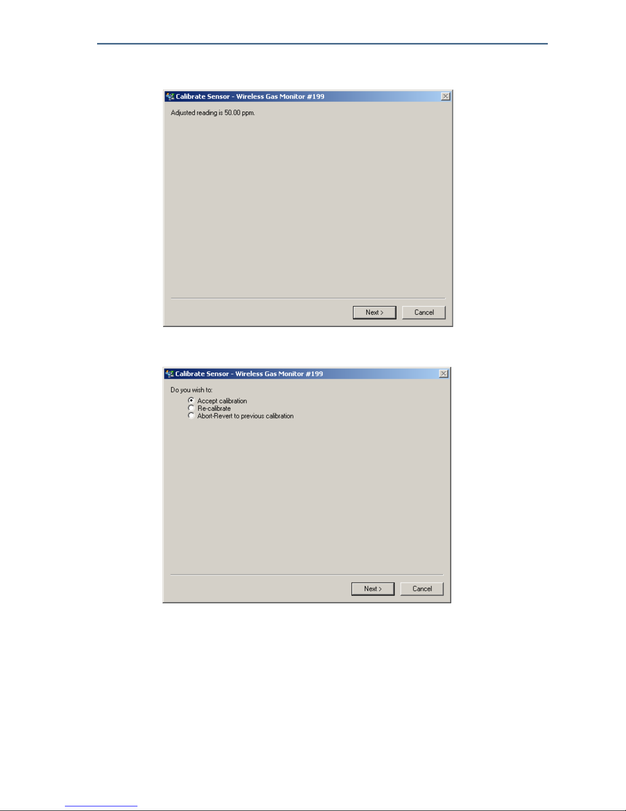
18.When the calibration process finishes, the new adjusted reading is displayed.
Select Next.
19.Select Accept calibration.
20.Select Next.

Quick Start Guide
51
August 2018
21.The Service Reminder screen is displayed if a service reminder is configured
and enabled. Select Next to accept the service reminder date or enter
another date. Refer to the “Service reminders” section of the Rosemount 928
Wireless Gas Monitor
Reference Manual for more information.
22.Shut off the target gas flow at the regulator.
23.Detach the calibration tubing from the regulator on the target gas source
and from the IP filter inlet on the bottom of the Rosemount 628 Gas Sensor
Module.
7.0 Manual setup
Manual setup includes all available configuration settings. It may be used to
change specific settings configured during initial setup without using the
Guided Setup menus. It may also be used to configure advanced, optional
settings.
Note
The Field Communicator Manual Setup configuration procedures in this quick start guide
were developed using Emerson™ AMS Trex Device Communicator. The menus are identical
to those found in other Field Communicators, but are navigated using touch screens rather
than fast keys. Refer to the manual for your handheld communicator device for more
information.
1. Connect the HART® communication leads to the HART terminals on the
handheld communicator.
August 2018
52
Quick Start Guide
2. Connect the HART communication leads to the COMM terminals on the
terminal block.
A. +Comm Terminal
B. -Comm Terminal
3. Start your handheld communicator device. If necessary, open HART Field
Communicator on your handheld device to establish HART communication.
Refer to the manual for your handheld communicator device for more
information.
4. On the Overview screen, select Configure.
Do not connect to the COMM terminals when an explosive atmosphere is present.

Quick Start Guide
53
August 2018
5. On the Configure screen, select Manual Setup.
6. Perform the configuration tasks in the following subsections as needed.
7.1 Configuring display options
The Primary Variable (Gas Concentration) is displayed by default on the LCD
display. To configure the display of additional dynamic variable items, do the
following:
Configuring display options using Field Communicator
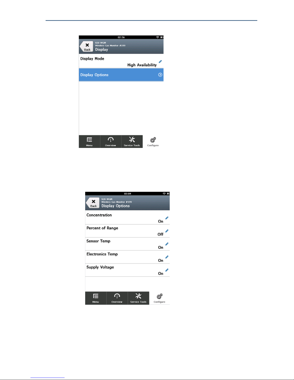
1. On the Manual Setup screen, select Display.
August 2018
54
Quick Start Guide
2. On the Display screen, select Display Options.
3. Select a display option or options to alternate displaying with the Primary
Variable (Gas Concentration).
Percent of Range
Gas Sensor Module Temperature
Electronics Temperature
Supply Voltage

Quick Start Guide
55
August 2018
4. Select On.
5. Select OK.
6. If required, repeat steps 3–5 for additional display options.
7. On the Display Options screen, select Send.
8. On the Send screen, do one or more of the following:
Select Display Options if you want to review the selected display items.
Select Cancel to return to the Display Options screen. Pending changes
to display options are preserved.
Select Discard to return to the display options screen and discard
pending changes. Select OK to confirm or Cancel to return to the
previous screen.

August 2018
56
Quick Start Guide
Select Send to send display option changes to the device.
9. Select Back twice to return to the Manual Setup screen.
Configuring display options using AMS Wireless Configurator
1. On the Manual Setup page, select the Display tab.
2. On the Display tab, select a display option or options to alternate displaying
with the Primary Variable (Gas Concentration).
Percent of Range
Gas Sensor Module Temperature
Electronics Temperature
Supply Voltage
3. Select Send.
Quick Start Guide
57
August 2018
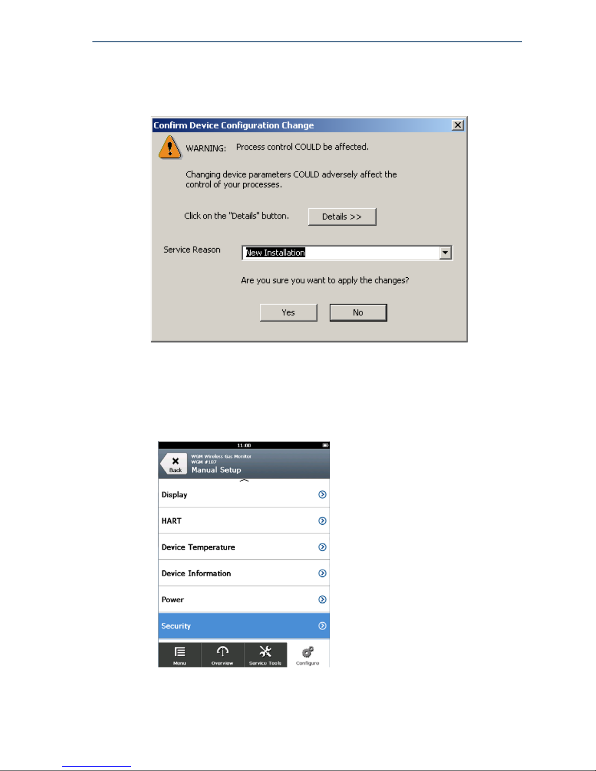
4. In the Confirm Device Configuration Change dialog box, select a reason for
the future service from the Service Reason list. Select Details if you want to
view additional information.
5. Select Yes.
7.2 Configuring security settings
You have the option to configure security settings to protect the Rosemount™
928 Wireless Gas Monitor from unauthorized configuration changes.
Configuring security settings using Field Communicator
1. On the Manual Setup screen, select Security.

August 2018
58
Quick Start Guide
2. Configure the following security settings as required:
Write Protect: If No (the default option) is selected, device configuration
settings may be viewed and edited. If Yes is selected, device
configuration settings may be viewed but not edited.
Lock Device: If Unlock is selected, the device can be accessed by any
host to view and edit configuration settings. If Lock (the default option) is
selected, the device cannot be accessed by any host to view and edit
configuration settings until a host unlocks the device. To change this
option, do the following:
a. On the Security screen, select Lock/Unlock.
b. On the Select HART Lock option screen, select Lock or Unlock to change
the setting.
c. Select OK.
On the Security screen, the Device is Locked area displays On when the device
is locked and Off when the device is unlocked.

Quick Start Guide
59
August 2018
Over the Air Upgrade: If Unlock (the default option) is selected, the
transmitter radio can be upgraded by programming sent over the air. If Lock
is selected, over-the-air transmitter radio upgrades are prevented.
Configuring security settings using AMS Wireless Configurator
1. On the Manual Setup page, select the Security tab.
2. Configure the following security settings as needed:
Write Protect: If No (the default option) is selected, device configuration
settings may be viewed and edited. If Yes is selected, prevents viewing
and editing the configuration settings.
Radio Upgrade: If Unlock (the default option) is selected, the
transmitter radio can be upgraded by programming sent over the air. If
Lock is selected, over-the-air transmitter radio upgrades are prevented.
Lock Device: If Unlock (the default option) is selected, the device can be
accessed by any host to view and edit configuration settings. If Lock is
selected, the device cannot be accessed by any host to view and edit
configuration settings until a host unlocks the device. To change this
option, do the following:
a. Select Lock/Unlock.

August 2018
60
Quick Start Guide
b. In the HART Lock list, select Lock or Unlock to change the setting.
c. Select Finish.
In the HART Lock area, the Device is Locked check box is selected when the
device is locked.
3. When finished making changes, select Send to update the device
configuration.

Quick Start Guide
61
August 2018
7.3 Configuring device information
You have the option to configure device information for the Rosemount 928
Wireless Gas Monitor.
Configuring device information using Field Communicator
1. On the Manual Setup screen, select Device Information.
2. On the Device Information screen, select any of the following and configure
as needed.
Long Tag: Enter an identifier for the device up to 32 characters long using
the virtual keypad. The Long Tag is blank by default and does not display if
left blank.

August 2018
62
Quick Start Guide
Tag: Enter an identifier for the device up to eight uppercase alphabetic
and numeric characters long using the virtual keypad. The Tag is blank by
default and does not display if left blank.
Descriptor: Enter a description of the device up to 16 alphabetic,
numeric, and special characters long. The Descriptor is blank by default
and does not display if left blank.
Message: Enter a message up to 32 alphabetic, numeric, and special
characters long. The Message is blank by default, does not display if left
blank, and may be used for any purpose.

Quick Start Guide
63
August 2018
Date: Enter a date in mm/dd/yyyy format using the virtual keypad. The
date may be used for any purpose, such as recording the date of the most
recent calibration.
3. When finished making changes, select Send.
4. On the Send screen, do one or more of the following:
Select Cancel to return to the Device Information screen. Pending
changes to display options are preserved.
Select Discard to return to the Device Information screen and discard
pending changes. Select OK to confirm or Cancel to return to the
previous screen.

August 2018
64
Quick Start Guide
Select Send to send display option changes to the device.
5. Select Back to return to the Manual Setup screen.
Configuring device information using AMS Wireless Configurator
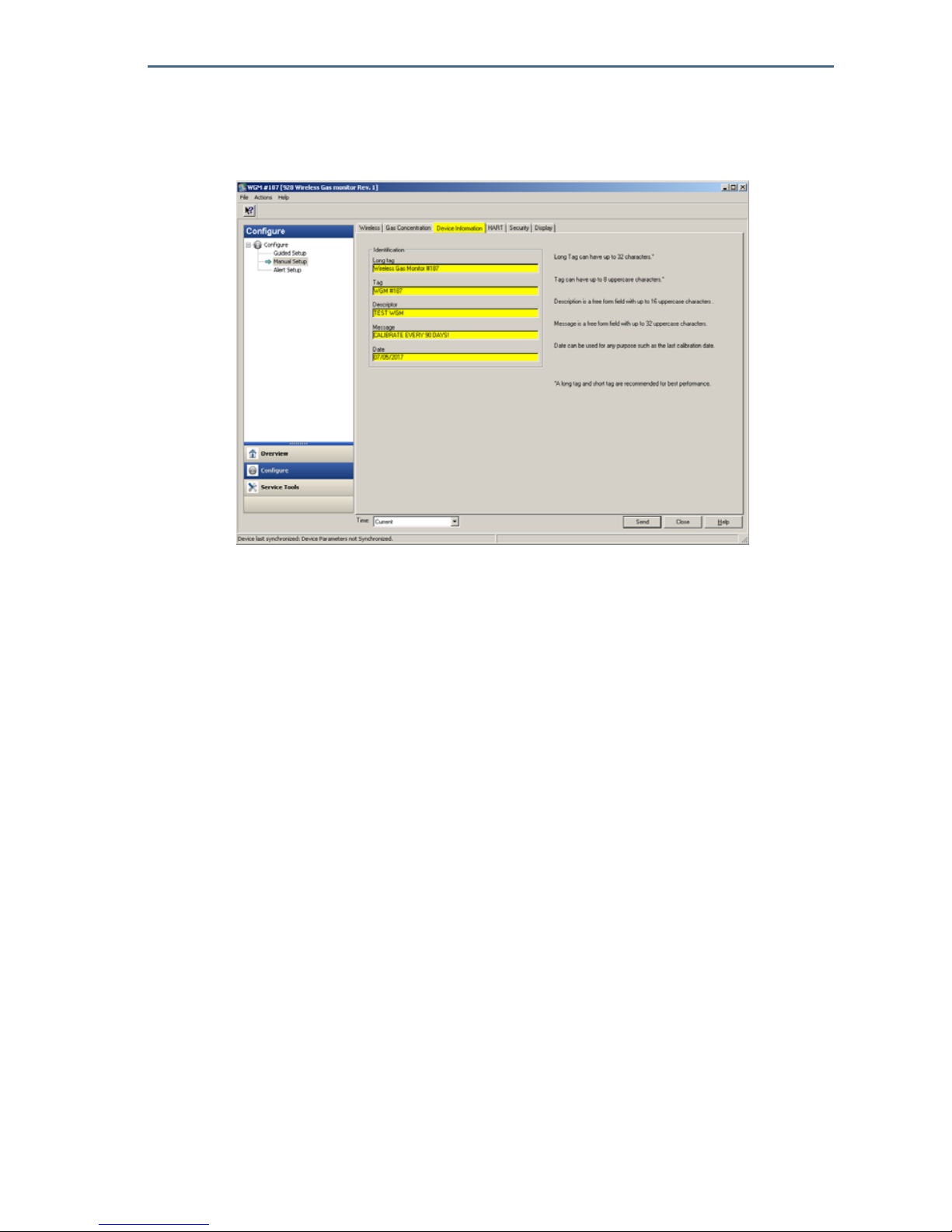
1. On the Manual Setup page, select the Device Information tab.
2. Enter the following as needed:
Long Tag: Enter an identifier for the device up to 32 characters long. The
Long Tag is blank by default and does not display if left blank.
Tag: Enter an identifier for the device up to eight uppercase alphabetic
and numeric characters long. The Tag is blank by default and does not
display if left blank.
Descriptor: Enter a description of the device up to 16 characters long.
The Descriptor is blank by default and does not display if left blank.
Quick Start Guide
65
August 2018
Message: Enter text up to 32 characters long. The Message is blank by
default, does not display if left blank, and may be used for any purpose.
Date: Enter a date in mm/dd/yyyy format. The date may be used for any
purpose, such as recording the date of the most recent calibration.
3. When finished making changes, select Send to update the device
configuration.
8.0 Wireless considerations
8.1 Power up sequence
The Rosemount™ 928 Wireless Transmitter and all other wireless devices should
be installed only after the Wireless Gateway has been installed and is
functioning properly. Install the Emerson
™
701 SmartPower Module—Black into
the Rosemount 928 Wireless Gas Monitor to power the device. Power up
Wireless devices in order of proximity from the Gateway, beginning with the
closest. This results in a simpler and faster network installation. Enable Active
Advertising on the Gateway to ensure that new devices join the network faster.
Refer to the reference manual for your Wireless Gateway for more information.
8.2 Antenna position
The antenna should be positioned vertically, either straight up or straight down
and should be, if the application requirements allow, approximately 3 ft. (1 m)
from any large structure, building, or conductive surface to allow for clear
communication with other devices.

August 2018
66
Quick Start Guide
Figure 3. Antenna Position
8.3 Conduit entries
Upon installation, ensure that each conduit entry is either sealed with a conduit
plug using appropriate thread sealant, or has a conduit fitting or cable gland
installed with appropriate thread sealant.
Figure 4. Conduit Entries
A. Conduit entries

Quick Start Guide
67
August 2018
8.4 Choosing an installation location and position
When choosing an installation location and position, take into account access to
the Rosemount
™
928 Transmitter for ease-of-use for the power module and
Rosemount 628 Gas Sensor Module replacement. For best performance, the
antenna should be vertical with space between objects in a parallel metal plane,
such as a pipe or metal framework, as the pipes or framework may adversely
affect the antenna’s performance.
The Rosemount 928 Wireless Gas Monitor is a diffusion-based gas monitor. This
means that the target gas must actually come into contact with the
electrochemical sensor for the device to register a signal. Each target gas has a
unique density and will behave differently depending on the density of the
surrounding atmosphere. For example, Hydrogen Sulfide is considered a
heavier-than-air gas and tends to settle in low-lying areas when released into the
air.
Install Rosemount 928 Wireless Gas Monitors with the sensor module facing
downwards. Devices fitted with sensors for heavier-than-air target gases should
be installed close to ground level, ideally between 12 in. above the ground and
the breathing zone of a worker (3–6 ft. above grade level).
9.0 Electrical
9.1 Handling the power module
The Rosemount™ 928 Wireless Gas Monitor is self-powered. The included
Emerson 701 SmartPower Module—Black contains two “C” size primary
lithium/thionyl chloride batteries. Each battery contains approximately 2.5
grams of lithium, for a total of 5 grams in each pack. Under normal conditions,
the battery materials are self-contained and are not reactive as long as the
batteries and the power module are maintained. Take care to prevent thermal,
electrical, or mechanical damage. Contacts should be protected to prevent
premature discharge.
9.2 Making electrical connections (928XSS01 and 928XUT01
only)
See Figure 4. Make connections through the cable entry in the side of the
connection head. Be sure to provide adequate clearance for cover removal.
Use caution when handling the power module
It may be damaged if dropped from heights in excess of 20 ft. (6.10 m).
August 2018
68
Quick Start Guide
10.0 Verifying operating atmosphere
Verify that the operating atmosphere of the Rosemount™ 928 Transmitter and
the Rosemount 628 Gas Sensor Module is consistent with the appropriate
hazardous locations certifications.
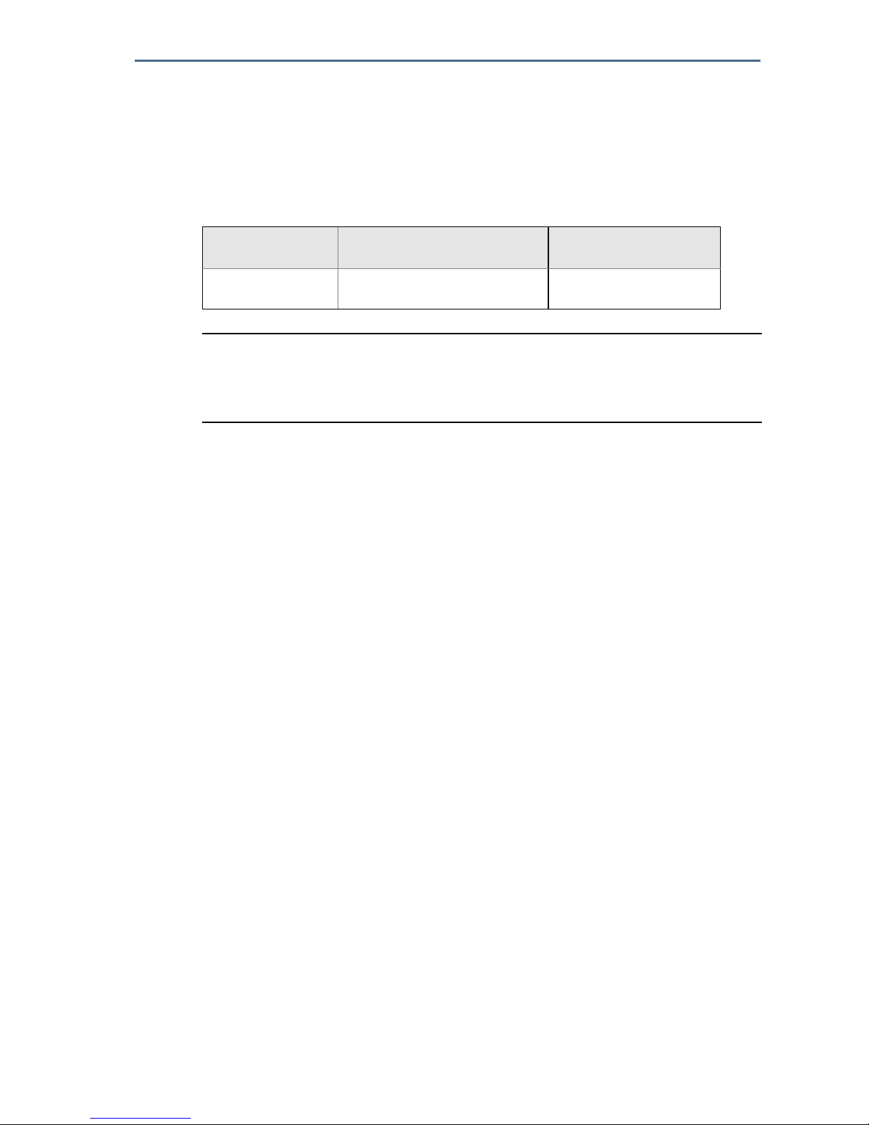
Table 1. Temperature Guidelines
Note
The electrochemical cells in sensor modules have a limited shelf life. Store sensor modules
in a cool location that is not excessively humid or dry. Storing sensor modules for periods
longer than three months may shorten their useful service life.
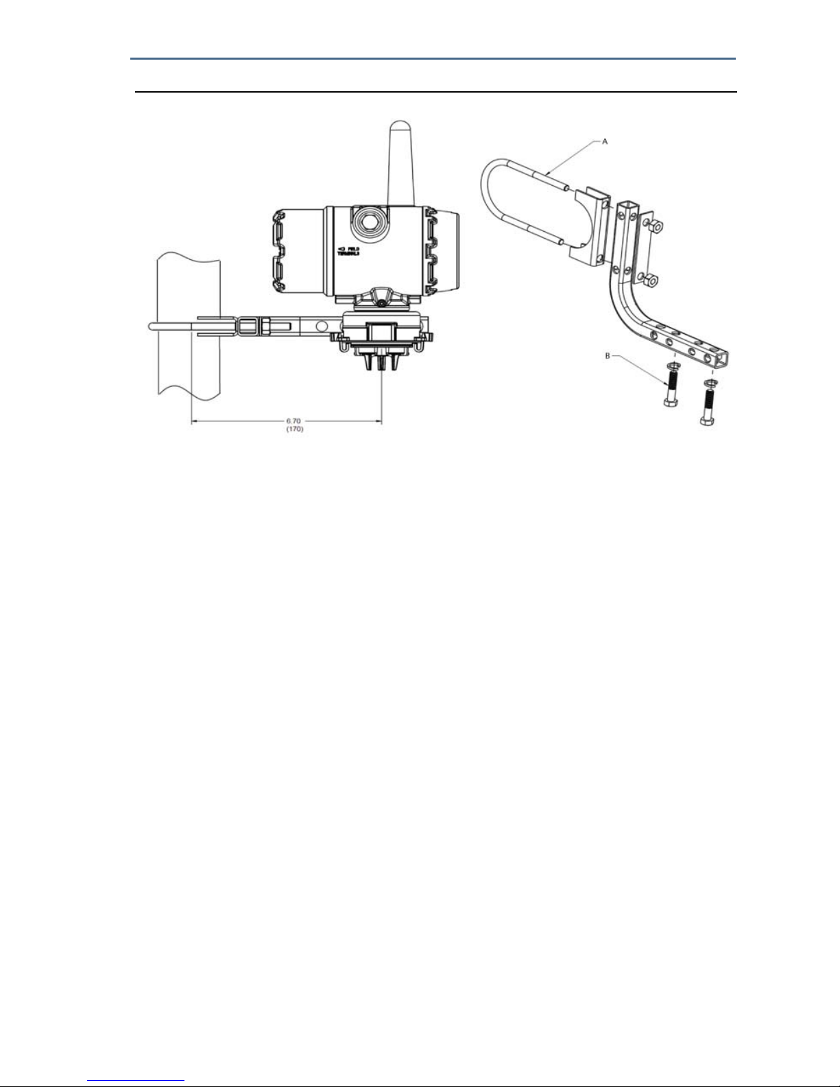
11.0 Installing the Rosemount™ 928 Transmitter
The Rosemount 928 Transmitter is designed to use the B4 Universal Mounting
Bracket. This curved, stainless steel bracket includes a U-bolt and fasteners for
mounting the Rosemount 928 Transmitter to a 2-in. pipe or pole. The B4
bracket attaches directly to the Rosemount 928 Transmitter. The B4 bracket
may also be used to in other mounting configurations such as mounting the
Rosemount 928 Transmitter to a wall or a panel.
11.1 Pipe mounting
Required equipment
Mounting Kit (part number 03151-9270-0004)
One 2-in. U-bolt assembly
One B4 mounting bracket
Two
5
/16-18. x 1 1/4-in. bolts
Two washers
A
1
/4-in. combination wrench or adjustable wrench
Operating limit Transmitter storage limit
Sensor storage
recommendation
-40 °F to 122 °F
-40 °C to 50 °C
-40 °F to 185 °F
-40 °C to 85 °C
34 °F to 45 °F
1 °C to 7 °C
Quick Start Guide
69
August 2018
Figure 5. Pipe Mounting
A. 2-in. bolt for pipe mounting (clamp shown)
B. 5/16-18 x 1 1/4-in. bolts for transmitter mounting
Dimensions are in inches (millimeters)
11.2 Panel mounting
Required equipment
Mounting Kit (part number 03151-9270-0004)
One B4 mounting bracket
Two
1
/4-in. x 1 1/4-in. bolts
A
5
/16-in. combination wrench or adjustable wrench
A
1
/4-in. combination wrench or adjustable wrench
Two
5
/16 - 18 bolts with nuts and washers (not included)

August 2018
70
Quick Start Guide
Figure 6. Panel Mounting
A. 5/16-18 bolts for panel mounting (not supplied)
B. 5/16-18 x 1 1/4-in. bolts for transmitter mounting
Dimensions are in inches (millimeters)
11.3 LCD display rotation
The LCD display can be rotated in 90° increments by squeezing the two tabs,
pulling the LCD display out, rotating, and snapping it back into place.
Note
Although the LCD display may be rotated, always install the Rosemount 928 Wireless Gas
Monitor with the Rosemount 628 Gas Sensor Module facing downwards.
If the LCD display pins are inadvertently removed from the interface board,
carefully reinsert the pins before snapping the LCD display back into place.
Note
Use only Rosemount Wireless LCD Display part number 00753-9004-0002.
11.4 Grounding the transmitter
The Rosemount 928 Transmitter operates with the housing grounded or
floating. Floating systems can cause extra noise that may affect many types of
readout devices. If the signal appears noisy or erratic, grounding at a single
point may solve the problem. The electronics enclosure should be grounded in
accordance with local and national installation codes. Grounding is
accomplished using the internal or external case grounding terminal.
Quick Start Guide
71
August 2018
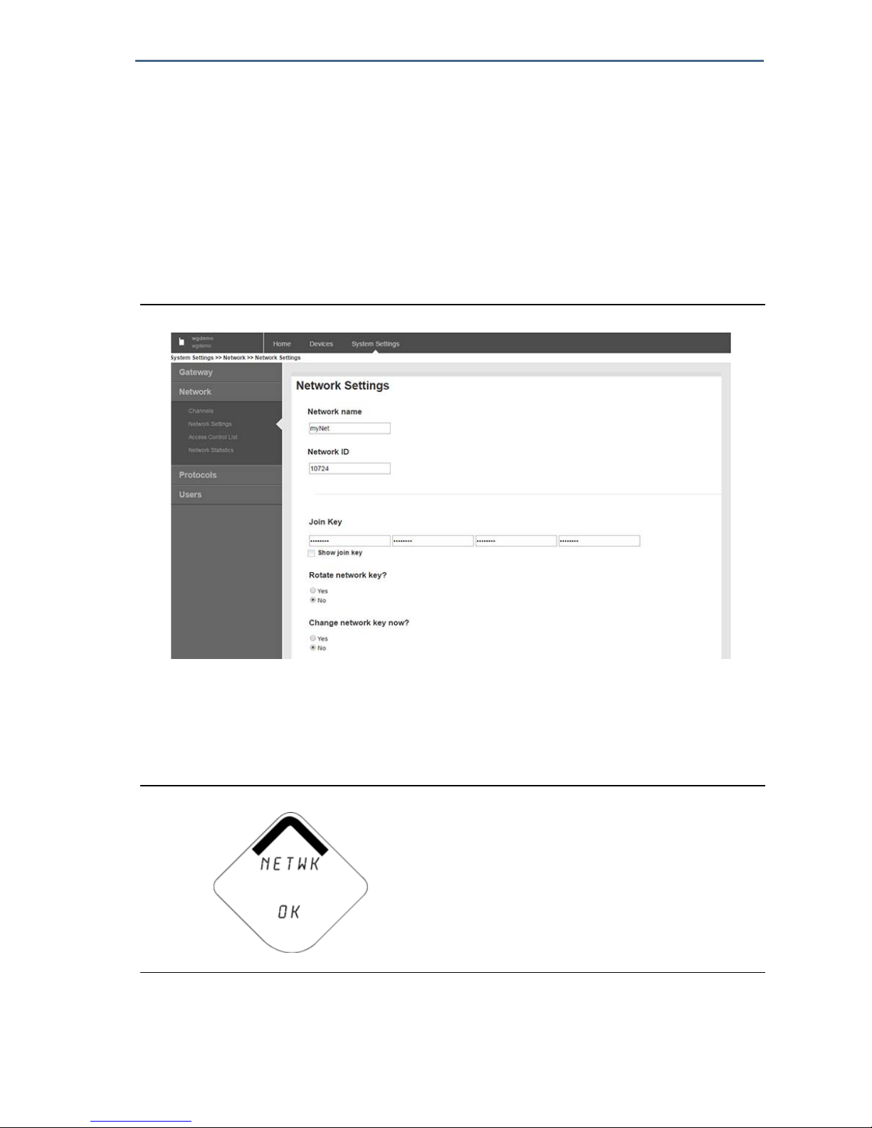
12.0 Verifying wireless network communication
In order to communicate with the Wireless Gateway, and ultimately the host
system, the transmitter must be configured to communicate with the wireless
network. This step is the wireless equivalent of connecting wires from a
transmitter to the host system. If the Network ID and Join Key are not identical,
the Rosemount
™
928 Transmitter will not communicate with the network. The
Network ID and Join Key may be obtained from the Wireless Gateway on the
Setup > Network > Settings page on the web server, shown in Figure 7. Refer to
“Joining the Rosemount 928 Transmitter to a wireless network” on page 21.
Figure 7. Gateway Network Settings
12.1 Verifying network join status
The chevron-shaped status bar at the top of the LCD display screen indicates the
progress of the network join process. When the status bar is filled, as shown in
Figure 8, the device is successfully connected to the wireless network.
Figure 8. Network Status Bar
August 2018
72
Quick Start Guide
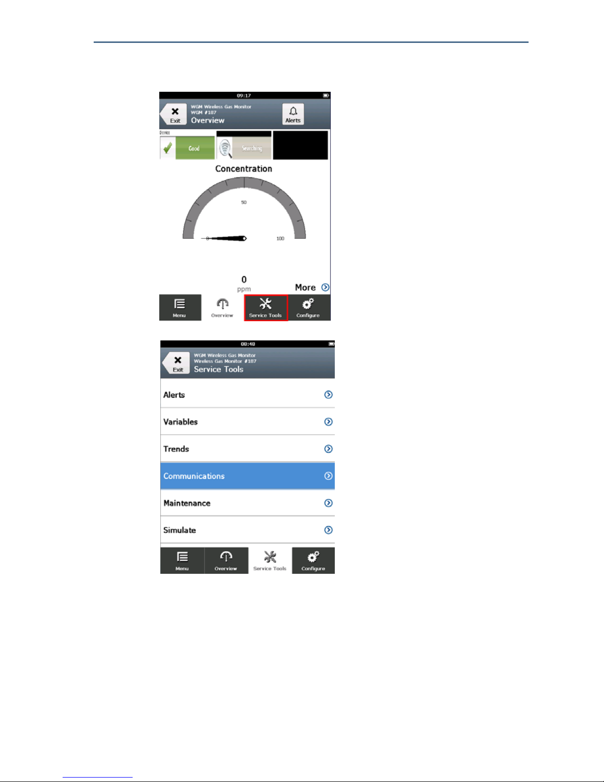
12.2 Verifying communication using Field Communicator
1. On the Overview screen, select Service Tools.
2. On the Service Tools screen, select Communications.
Quick Start Guide
73
August 2018
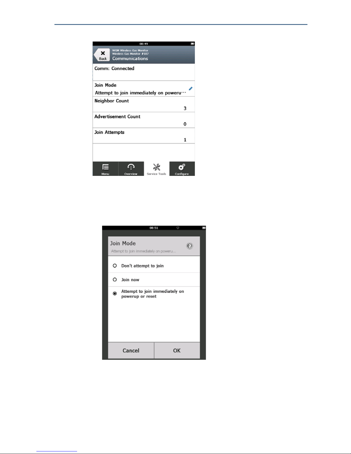
3. View the following communications information:
Communication Status: Displays whether the device is connected to the
wireless network.
Join Mode: Displays the current join mode. Select Join Mode to change
the way that the device joins the wireless network. Attempt to join
immediately on powerup or reset is the default option. Select Send
twice to update the Join Mode.
Neighbor Count: Displays the number of available neighboring devices.
Advertisement Count: Displays the number of advertisement packets
received.
4. When finished, select Back to return to the Communications screen.

August 2018
74
Quick Start Guide
12.3 Verifying communication using AMS Wireless Configurator
1. Open AMS Wireless Configurator.
2. In the Device Manager pane, expand the wireless network menu.
3. Expand the wireless gateway menu.
4. Select the Device List.
5. In the device pane, double-click the device icon.
6. Select Service Tools.
7. In the Service Tools pane, select Communications.
8. On the Communications tab, in the Join Status area, verify that all four
network join steps are completed.

Quick Start Guide
75
August 2018
12.4 Verifying communication using the Wireless Gateway
Open the Smart Wireless Gateway web interface. This page shows whether the
device has joined the network and is communicating properly.
13.0 Verifying operation
There are four ways to verify operation: using the Rosemount™ 928 Transmitter
LCD display, using a handheld communication device, using the Wireless
Gateway's integrated web interface, or by using AMS Wireless Configurator. If
the Rosemount 928 Transmitter was configured with the Network ID and Join
Key, and sufficient time has passed, it will be connected to the network.
When the device has joined the network, it will be displayed in the Device
Manager
13.1 Verifying LCD display operation
1. Verify that the display items are correct.
The LCD display shows the Primary Variable (Gas Concentration) by default. The
other variables are:
Secondary Variable (Gas Sensor Module Temperature)
Tertiary Variable (Electronics Temperature)
Quaternary Variable (Supply Voltage)
These variables may be configured to alternate displaying with the Primary
Variable at the configured update rate. Refer to “Configuring display options”

August 2018
76
Quick Start Guide
on page 53 if the display items need to be changed.
2. Verify that the Display Mode is correct. Refer to “Configuring device display
mode” on page 25 if the display mode needs to be changed.
Disabled: The display is turned off. This is useful if the display will never
be viewed locally.
On Demand: The display is on when the Rosemount 928 Wireless Gas
Monitor is connected to a handheld communication device or when it
receives a signal from its Wireless Gateway.
Periodic: The display is on only during updates at the configured update
rate.
High Availability: The display is always on regardless of the configured
update rate. This is the default display mode option.
3. Press the Diagnostic button to display the TAG, Device ID, Network ID,
Network Join Status, and Device Status screens.
13.2 If there is an immediate alarm
If the alarm is false, it is likely due to sensor configuration. Verify the sensor
configuration, alert set points, and alarm set points.
If the device joins the network and immediately issues an alarm, respond as though the alarm is real until it is
proven false.

Quick Start Guide
77
August 2018
Figure 9. Wireless Gateway Explorer Home Page
13.3 Communication troubleshooting
If the device is not joined to the network after power up, verify the correct
configuration of the Network ID and Join Key, and verify that Active Advertising
has been enabled on the Wireless Gateway. The Network ID and Join Key in the
device must match the Network ID and Join Key of the Wireless Gateway.
The Network ID and Join Key may be obtained from the Wireless Gateway on the
Setup> Network > Settings page on the web interface. The Network ID and Join
Key may be changed if necessary. Refer to “Joining the Rosemount 928
Transmitter to a wireless network” on page 21.
14.0 External alarm device alarm connections
An optional, customer-supplied external alarm device may be triggered by the
discrete output of the Rosemount
™
928 Wireless Gas Monitor (Models
928XSS01 and 928UTX01).
Note
The Rosemount 928 Wireless Gas Monitor cannot power external devices. It acts as a
switch that closes the power circuit of a connected external device when activated by a
HI-HI alarm if configured to do so.
An external power supply and alert device can be configured to issue a local
alarm when the detected gas concentration level exceeds the specified High
Concentration Threshold. The local alarm can be configured to latch the alarm
output until the alarm is manually cleared. The device may be queried to detect
whether this option is installed. Examples of alarm mechanism options include:
Audible alarm
Visual alarm (for example, a flashing light)

August 2018
78
Quick Start Guide
Initiate action (for example, close valves, initiate facility evacuation, call
emergency services)
There are two possible connection methods for the external alarm device:
Four-wire: This connection method (most common) uses a set of two wires
for an IS input power supply. Another set of two input wires is used for a
separate IS alarm mechanism.
Two-wire: This connection method combines an IS power source, such as an
internal battery, and an alarm device into one package.
An optional, customer-supplied alarm suppression button may also be added.
14.1 Connecting an external alarm device
1. On the Rosemount™ 928 Wireless Gas Monitor main housing, remove the
rear housing cover to expose the terminal block.
A. +Barrier Power
B. -Barrier Power
C. +Output to Alarm
D. -Output to Alarm
E. +Comm Terminal
F. -Comm Terminal
2. On the Rosemount 928 Wireless Gas Monitor main housing, remove one of
the conduit plugs.
If installing an optional, customer-supplied external alarm device, verify proper function.
Verify that gas concentrations in the area have dissipated to a safe level before clearing local or digital
alarms.
When connecting an external device to the Rosemount 928 Wireless Gas Monitor’s discrete output in a
hazardous area, ensure that the external device is installed in accordance with Intrinsically Safe or
non-incendive field wiring practices.
The Rosemount 928 Wireless Gas Monitor does not need to be connected to a wireless network for the
external alarm device to function. However, the low battery, no measurement, or sensor failure alerts will
not be available.

Quick Start Guide
79
August 2018
3. Route the barrier power and alarm output wiring into the Rosemount 928
Wireless Gas Monitor main housing.
4. Connect the wiring to the external device on the Rosemount 928 Wireless
Gas Monitor terminal block according to the terminal labels. Do one of the
following:
Perform four wire installation. This is the most common configuration.
Refer to the following diagram.
Note
Alarm wiring should be shielded for noise immunity.
Perform two wire installation. Refer to the following diagram.
5. Connect the wiring to the external device according to the manufacturer’s
instructions.

August 2018
80
Quick Start Guide
6. Verify that the external device functions properly.
Perform a bump test. Refer to the Bump Testing section in the
Rosemount 928 Wireless Gas Monitor
Reference Manual.
If available, use the external device’s manual test function to verify proper
function. Refer to the external device documentation for more
information.
15.0 Product certifications
Rev 1.0
15.1 European Union Directive information
The most recent revision of the EC Declaration of Conformity can be found at
www.Emerson.com/Rosemount under Documentation.
15.2 Telecommunication compliance
All wireless devices require certification to ensure that they adhere to
regulations regarding the use of the RF spectrum. Nearly every country requires
this type of product certification. Emerson
™
is working with governmental
agencies around the world to supply fully compliant products and remove the
risk of violating country directives or laws governing wireless device usage.
15.3 FCC and IC
This device complies with Part 15 of the FCC Rules. Operation is subject to the
following conditions: This device may not cause harmful interference. This
device must accept any interference received, including interference that may
cause undesired operation.
This device must be installed to ensure a minimum antenna separation distance
of 20 cm from all persons.
15.4 Ordinary location certification
As standard, the transmitter has been examined and tested to determine that
the design meets basic electrical, mechanical, and fire protection requirements
by a nationally recognized testing laboratory (NRTL) as accredited by the Federal
Occupational Safety and Health Administration (OSHA).
15.5 Installing in North America
The U.S. National Electrical Code® (NEC) and Canadian Electrical Code (CEC)
permit the use of Division-marked in Zones and Zone-marked equipment in
Divisions. The markings must be suitable for the area classification, gas, and
temperature class. This information is clearly defined in their respective codes.
15.6 Hazardous location certificates
U.S.A.
I5 U.S.A. Intrinsically Safe (IS)
Certificate: CSA 70138122

Quick Start Guide
81
August 2018
Standards: FM 3600–2011, FM 3610–2010, UL Standard 50—11th edition, UL 61010–1—
3rd edition, ANSI/ISA–60079–0 (12.00.01)–2013, ANSI/ISA–60079–11
(12.02.01)–2013
Markings: IS CL I, DIV 1, GP A, B, C, D, T4;
Class 1, Zone 0, AEx ia IIC T4 Ga;
T4 (-40 °C Ta +50 °C) when installed according to Rosemount drawing
00928-1010; Type 4X
Table 2. Entity Parameters
Special Conditions for Safe Use (X):
1. For use only with the Emerson™ Model 701BKKF, the Computational Systems Inc.
MHM-89004, or the Perpetuum Ltd. IPM1008/IPM74001.
2. The surface resistivity of the antenna is greater than 1 Gigaohm. To avoid electrostatic
discharge buildup, it must not be rubbed or cleaned with solvents or a dry cloth.
3. Substitution of components may impair intrinsic safety.
Canada
I6 Canada Intrinsically Safe
Certificate: CSA 70138122
Standards: CAN/CSA C22 No. 0–10 C22.2 No. 94-M91, CSA Std C22.2 No. 142-1987,
CAN/CSA-60079-0–2011, CAN/CSA-60079-11–2014, CAN/CSA-61010-1–
2012
Markings: IS CL I, DIV 1, GP A, B, C, D, T4;
Ex ia IIC T4 Ga;
T4 (-40 °C Ta +50 °C) when installed according to Rosemount drawing
00928-1010; Type 4X
Refer to Table 2.
Special Conditions for Safe Use (X):
1. For use only with the Emerson Model 701BKKF, the Computational Systems Inc.
MHM-89004, or the Perpetuum Ltd. IPM1008/IPM74001.
2. The surface resistivity of the antenna is greater than 1 Gigaohm. To avoid electrostatic
discharge buildup, it must not be rubbed or cleaned with solvents or a dry cloth.
3. Substitution of components may impair intrinsic safety.
Europe
I1 ATEX Intrinsic Safety
Certificate: Sira17ATEX2371X
Standards: EN 60079-0:2012 + A11:2013, EN 60079-11:2012
Markings: II1 G Ex ia IIC T4 Ga, T4
(-40 °C ≤ Ta ≤ +50 °C) IP66
Refer to Table 2.
Alarm Circuit Terminal Input/Output Parameters
Vmax/Ui = Voc/Uo = 28V
Imax/Ii = Isc Io = 93.3 mA
Pmax/Pi = Pmax/Po = 653mW
Ci = 5.72nF
Li = 0mH

August 2018
82
Quick Start Guide
Special Conditions for Safe Use (X):
1. Under certain extreme circumstances, the non-metallic parts incorporated in the
enclosure of this equipment may generate an ignition-capable of electrostatic charge.
Therefore the equipment shall not be installed in a location where the external
conditions are conducive to the build-up of electrostatic charge on such surfaces. In
addition, the equipment shall only be cleaned with a damp cloth.
2. The transmitter may contain more than 10% aluminum and is considered a potential
risk ignition by impact or friction. Care must be taken into account during installation
and use to prevent impact or friction.
3. The equipment shall be powered by Emerson 701BKKF. An alternative power source
shall be the CSI MHM-89004 as this device has output parameters are equal to or less
onerous than the parameters of the 701BKKF.
4. Only the 375, 475, or AMS Trex Communicators may be used with the 928.
International
I7 IECEx Intrinsic Safety
Certificate: IECEx SIR 17.0091X
Standards: IEC 60079-0:2011, IEC 60079-11:2011
Markings: Ex ia IIC T4 Ga, T4 (-40 °C ≤ Ta ≤ +50 °C) IP66
Refer to Table 2.
Special Conditions for Safe Use (X):
1. Under extreme circumstances, the non-metallic parts incorporated in the enclosure of
this equipment may generate an ignition-capable level of electrostatic charge.
Therefore the equipment shall not be intalled in a location where the external
conditions are conducive to the build-up of electrostatic charge on such surfaces. In
addition, the equipment shall only be cleaned with a damp cloth.
2. The transmitter may contain more than 10% aluminum and is considered a potential
risk ignition by impact or friction. Care must be taken into account during installation
and use to prevent impact or friction.
3. The equipment shall be powered by Emerson™ 701BKKF. An alternative power source
shall be the CSI MHM-89004 as this device has output parameters are equal to or less
onerous than the parameters of the 701BKKF.
4. Only the 375, 475, or AMS Trex Communicators may be used with the 928.
Quick Start Guide
83
August 2018
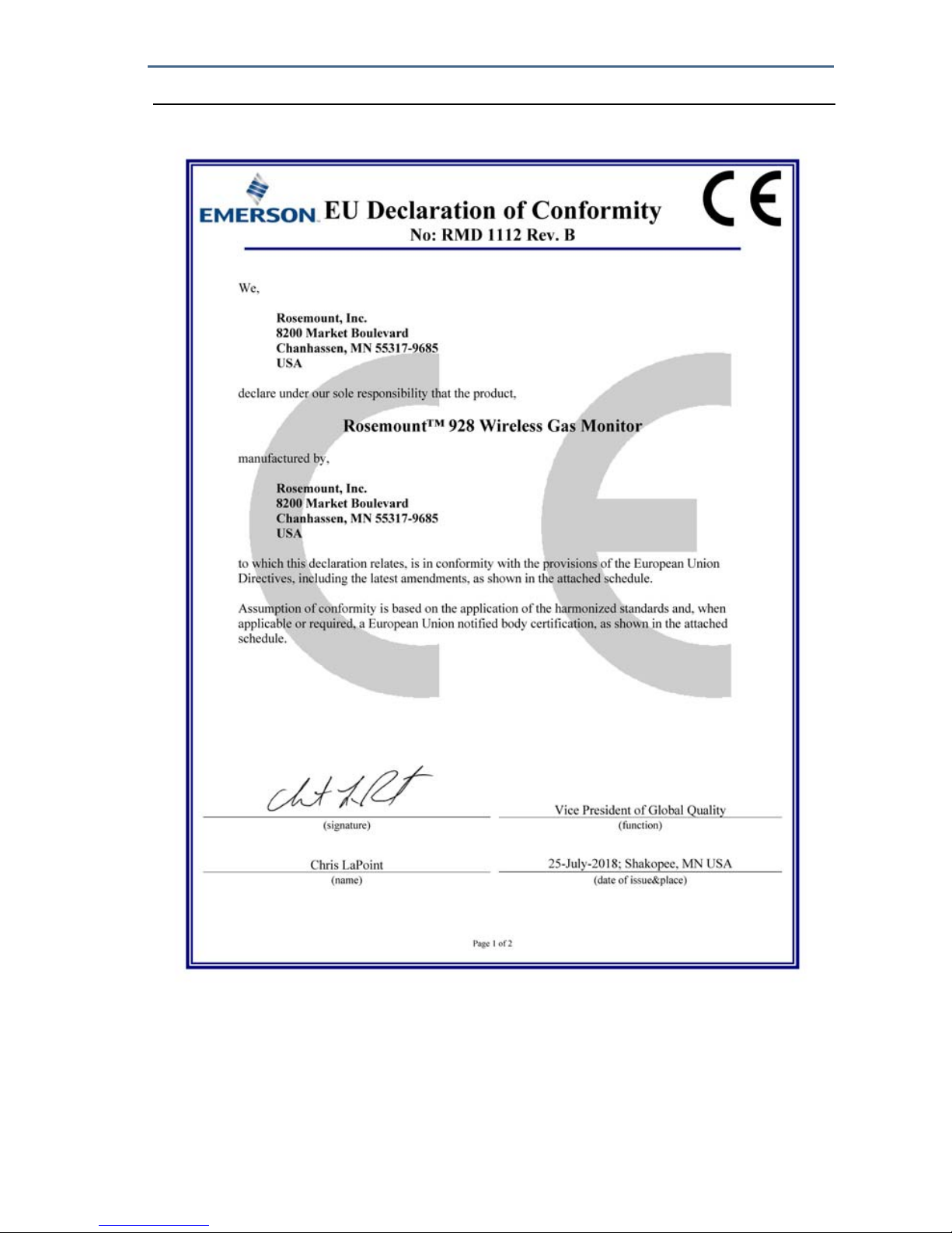
Figure 10. Declaration of Conformity Page 1
July 2018
84
Quick Start Guide
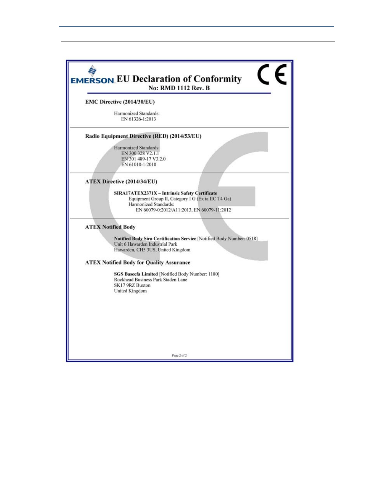
Figure 10. Declaration of Conformity Page 2

Quick Start Guide
85
August 2018

Global Headquarters
Emerson Automation Solutions
6021 Innovation Blvd.
Shakopee, MN 55379, USA
+1 800 999 9307 or +1 952 906 8888
+1 952 949 7001
RFQ.RMD-RCC@Emerson.com
North America Regional Office
Emerson Automation Solutions
8200 Market Blvd.
Chanhassen, MN 55317, USA
+1 800 999 9307 or +1 952 906 8888
+1 952 949 7001
RMT-NA.RCCRFQ@Emerson.com
Latin America Regional Office
Emerson Automation Solutions
1300 Concord Terrace, Suite 400
Sunrise, FL 33323, USA
+1 954 846 5030
+1 954 846 5121
RFQ.RMD-RCC@Emerson.com
Linkedin.com/company/Emerson-Automation-Solutions
Twitter.com/Rosemount_News
Facebook.com/Rosemount
Youtube.com/user/RosemountMeasurement
Google.com/+RosemountMeasurement
Standard Terms and Conditions of Sale can be found on the
Terms
and Conditions of Sale page.
The Emerson logo is a trademark and service mark of Emerson
Electric Co.
Rosemount is a trademark of Rosemount, Inc.
AMS Trex, Rosemount, and Rosemount logotype are trademarks of
Emerson.
HART and WirelessHART are trademarks of the FieldComm Group.
National Electric Code is a registered trademark of National Fire
Protection Association, Inc.
All other marks are the property of their respective owners.
© 2018 Emerson. All rights reserved.
Europe Regional Office
Emerson Automation Solutions
Neuhofstrasse 19a P.O. Box 1046
CH 6340 Baar
Switzerland
+41 (0) 41 768 6111
+41 (0) 41 768 6300
RFQ.RMD-RCC@Emerson.com
Asia Pacific Regional Office
Emerson Automation Solutions
1 Pandan Crescent
Singapore 128461
+65 6777 8211
+65 6777 0947
Enquiries@AP.Emerson.com
Middle East and Africa Regional Office
Emerson Automation Solutions
Emerson FZE P.O. Box 17033
Jebel Ali Free Zone - South 2
Dubai, United Arab Emirates
+971 4 8118100
+971 4 8865465
RFQ.RMTMEA@Emerson.com
Quick Start Guide
00825-0100-4928, Rev AB
August 2018
 Loading...