

Page 1
Reference Manual
00809-0100-4665, Rev AA
August 2010
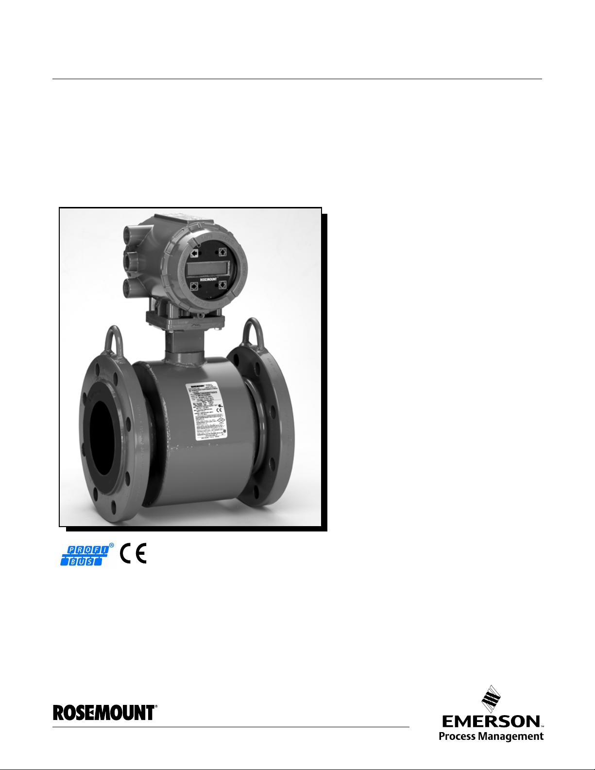
Rosemount 8732
Integral Mount or Remote Mount Magnetic
Flowmeter System with Profibus-PA
www.rosemount.com
Page 2

Page 3

Reference Manual
NOTICE
00809-0100-4665, Rev AA
August 2010
Rosemount 8732
Integral Mount or Remote Mount
Magnetic Flowmeter System with
Profibus-PA
Read this manual before working with the product. For personal and system safety, and for
optimum product performance, make sure you thoroughly understand the contents before
installing, using, or maintaining this product.
Rosemount Inc. has two toll-free assistance numbers:
Customer Central
Technical support, quoting, and order-related questions.
United States - 1-800-999-9307 (7:00 am to 7:00 pm CST)
Asia Pacific- 65 777 8211
Europe/ Middle East/ Africa - 49 (8153) 9390
North American Response Center
Equipment service needs.
1-800-654-7768 (24 hours—includes Canada)
Outside of these areas, contact your local Emerson Process Management representative.
The products described in this document are NOT designed for nuclear-qualified
applications. Using non-nuclear qualified products in applications that require
nuclear-qualified hardware or products may cause inaccurate readings.
For information on Rosemount nuclear-qualified products, contact your local Emerson
Process Management Sales Representative.
www.rosemount.com
Page 4

Page 5

Reference Manual
00809-0100-4655, Rev AA
August 2010
Rosemount 8732
Table of Contents
SECTION 1
Introduction
SECTION 2
Installation
SECTION 3
Configuration
SECTION 4
Operation
System Description. . . . . . . . . . . . . . . . . . . . . . . . . . . . . . . . . . . . . . . 1-1
Safety Messages . . . . . . . . . . . . . . . . . . . . . . . . . . . . . . . . . . . . . . . . 1-2
Service Support . . . . . . . . . . . . . . . . . . . . . . . . . . . . . . . . . . . . . . . . . 1-2
Safety Messages . . . . . . . . . . . . . . . . . . . . . . . . . . . . . . . . . . . . . . . . 2-1
Transmitter Symbols. . . . . . . . . . . . . . . . . . . . . . . . . . . . . . . . . . . . . . 2-2
Pre-Installation . . . . . . . . . . . . . . . . . . . . . . . . . . . . . . . . . . . . . . . . . . 2-2
Mechanical Considerations. . . . . . . . . . . . . . . . . . . . . . . . . . . . . . . . . 2-2
Environmental Considerations . . . . . . . . . . . . . . . . . . . . . . . . . . . . . . 2-3
Installation Procedures . . . . . . . . . . . . . . . . . . . . . . . . . . . . . . . . . . . . 2-3
Sensor Connections . . . . . . . . . . . . . . . . . . . . . . . . . . . . . . . . . . . . . 2-10
Quick Start-Up . . . . . . . . . . . . . . . . . . . . . . . . . . . . . . . . . . . . . . . . . . 3-1
Assigning Device Tag and Node Address . . . . . . . . . . . . . . . . . . . . . 3-2
Basic Setup. . . . . . . . . . . . . . . . . . . . . . . . . . . . . . . . . . . . . . . . . . . . . 3-2
Transducer Block . . . . . . . . . . . . . . . . . . . . . . . . . . . . . . . . . . . . . . . . 3-7
PV. . . . . . . . . . . . . . . . . . . . . . . . . . . . . . . . . . . . . . . . . . . . . . . . . . . . 3-7
Basic Setup. . . . . . . . . . . . . . . . . . . . . . . . . . . . . . . . . . . . . . . . . . . . . 3-7
Introduction . . . . . . . . . . . . . . . . . . . . . . . . . . . . . . . . . . . . . . . . . . . . . 4-1
Local Operator Interface. . . . . . . . . . . . . . . . . . . . . . . . . . . . . . . . . . . 4-1
Diagnostics . . . . . . . . . . . . . . . . . . . . . . . . . . . . . . . . . . . . . . . . . . . . . 4-3
Advanced Configuration . . . . . . . . . . . . . . . . . . . . . . . . . . . . . . . . . . 4-12
Detailed Setup . . . . . . . . . . . . . . . . . . . . . . . . . . . . . . . . . . . . . . . . . 4-12
SECTION 5
Sensor Installation
SECTION 6
Maintenance and
Troubleshooting
APPENDIX A
Reference Data
Safety Messages . . . . . . . . . . . . . . . . . . . . . . . . . . . . . . . . . . . . . . . . 5-1
Sensor Handling . . . . . . . . . . . . . . . . . . . . . . . . . . . . . . . . . . . . . . . . . 5-3
Sensor Mounting. . . . . . . . . . . . . . . . . . . . . . . . . . . . . . . . . . . . . . . . . 5-4
Installation (Flanged Sensor) . . . . . . . . . . . . . . . . . . . . . . . . . . . . . . . 5-7
Installation (Wafer Sensor) . . . . . . . . . . . . . . . . . . . . . . . . . . . . . . . . 5-10
Installation (Sanitary Sensor) . . . . . . . . . . . . . . . . . . . . . . . . . . . . . . 5-12
Grounding. . . . . . . . . . . . . . . . . . . . . . . . . . . . . . . . . . . . . . . . . . . . . 5-12
Process Leak Protection (Optional) . . . . . . . . . . . . . . . . . . . . . . . . . 5-16
Safety Information. . . . . . . . . . . . . . . . . . . . . . . . . . . . . . . . . . . . . . . . 6-1
Installation Check and Guide . . . . . . . . . . . . . . . . . . . . . . . . . . . . . . . 6-2
Diagnostic Messages . . . . . . . . . . . . . . . . . . . . . . . . . . . . . . . . . . . . . 6-3
Transmitter Troubleshooting. . . . . . . . . . . . . . . . . . . . . . . . . . . . . . . . 6-5
Quick Troubleshooting . . . . . . . . . . . . . . . . . . . . . . . . . . . . . . . . . . . . 6-7
Functional Specifications . . . . . . . . . . . . . . . . . . . . . . . . . . . . . . . . . . A-1
E-Series Advanced Diagnostics Capabilities . . . . . . . . . . . . . . . . . . . A-4
Output Signals . . . . . . . . . . . . . . . . . . . . . . . . . . . . . . . . . . . . . . . . . . A-4
Profibus PA fieldbus Digital Output Specifications . . . . . . . . . . . . . . . A-4
Performance Specifications . . . . . . . . . . . . . . . . . . . . . . . . . . . . . . . . A-6
Physical Specifications . . . . . . . . . . . . . . . . . . . . . . . . . . . . . . . . . . . . A-8
Ordering Information. . . . . . . . . . . . . . . . . . . . . . . . . . . . . . . . . . . . . . A-9
TOC-1
Page 6

Rosemount 8732
Reference Manual
00809-0100-4655, Rev AA
August 2010
APPENDIX B
Approval Information
APPENDIX C
Diagnostics
APPENDIX D
Digital Signal Processing
APPENDIX E
Universal Sensor Wiring
Diagrams
Product Certifications. . . . . . . . . . . . . . . . . . . . . . . . . . . . . . . . . . . . . .B-1
Sensor Approval . . . . . . . . . . . . . . . . . . . . . . . . . . . . . . . . . . . . . . . . .B-5
Diagnostic Availability . . . . . . . . . . . . . . . . . . . . . . . . . . . . . . . . . . . . .C-1
Licensing and Enabling . . . . . . . . . . . . . . . . . . . . . . . . . . . . . . . . . . . .C-2
Tunable Empty Pipe Detection . . . . . . . . . . . . . . . . . . . . . . . . . . . . . .C-2
Ground/Wiring Fault Detection . . . . . . . . . . . . . . . . . . . . . . . . . . . . . .C-4
High Process Noise Detection. . . . . . . . . . . . . . . . . . . . . . . . . . . . . . .C-5
8714i Meter Verification. . . . . . . . . . . . . . . . . . . . . . . . . . . . . . . . . . . .C-8
Rosemount Magnetic Flowmeter Calibration Verification Report . . .C-14
Safety Messages. . . . . . . . . . . . . . . . . . . . . . . . . . . . . . . . . . . . . . . . .D-1
Procedures . . . . . . . . . . . . . . . . . . . . . . . . . . . . . . . . . . . . . . . . . . . . .D-2
Rosemount Sensors . . . . . . . . . . . . . . . . . . . . . . . . . . . . . . . . . . . . . .E-3
Brooks Sensors . . . . . . . . . . . . . . . . . . . . . . . . . . . . . . . . . . . . . . . . . .E-6
Endress And Hauser Sensors . . . . . . . . . . . . . . . . . . . . . . . . . . . . . . .E-8
Fischer And Porter Sensors. . . . . . . . . . . . . . . . . . . . . . . . . . . . . . . . .E-9
Foxboro Sensors . . . . . . . . . . . . . . . . . . . . . . . . . . . . . . . . . . . . . . . .E-15
Kent Veriflux VTC Sensor . . . . . . . . . . . . . . . . . . . . . . . . . . . . . . . . .E-19
Kent Sensors. . . . . . . . . . . . . . . . . . . . . . . . . . . . . . . . . . . . . . . . . . .E-20
Krohne Sensors. . . . . . . . . . . . . . . . . . . . . . . . . . . . . . . . . . . . . . . . .E-21
Taylor Sensors. . . . . . . . . . . . . . . . . . . . . . . . . . . . . . . . . . . . . . . . . .E-22
Yamatake Honeywell Sensors. . . . . . . . . . . . . . . . . . . . . . . . . . . . . .E-24
Yokogawa Sensors . . . . . . . . . . . . . . . . . . . . . . . . . . . . . . . . . . . . . .E-25
Generic Manufacturer Sensors . . . . . . . . . . . . . . . . . . . . . . . . . . . . .E-26
APPENDIX F
Physical Block
APPENDIX G
Transducer Block
APPENDIX H
GSD File for Rosemount
8732E Magnetic Flow
Transmitter
Physical Block Parameter Attribute Definitions . . . . . . . . . . . . . . . . . .F-1
I&M Parameters. . . . . . . . . . . . . . . . . . . . . . . . . . . . . . . . . . . . . . . . . .F-4
Transducer Block Parameter Attribute Definitions. . . . . . . . . . . . . . . .G-1
Profibus DP . . . . . . . . . . . . . . . . . . . . . . . . . . . . . . . . . . . . . . . . . . . . .H-1
Basic DP Slave Related Keywords . . . . . . . . . . . . . . . . . . . . . . . . . . .H-1
Module Related Information. . . . . . . . . . . . . . . . . . . . . . . . . . . . . . . . .H-2
Description of extended DP features. . . . . . . . . . . . . . . . . . . . . . . . . .H-2
Description of physical interface for async. and sync. transmission . .H-2
Description of device related diagnosis . . . . . . . . . . . . . . . . . . . . . . . .H-2
Extended Diagnostic Bytes - Manufacturer Specific . . . . . . . . . . . . . .H-3
Module Details. . . . . . . . . . . . . . . . . . . . . . . . . . . . . . . . . . . . . . . . . . .H-3
Description of the module assignment. . . . . . . . . . . . . . . . . . . . . . . . .H-4
Valid Configurations. . . . . . . . . . . . . . . . . . . . . . . . . . . . . . . . . . . . . . .H-4
TOC-2
Page 7

Reference Manual
00809-0100-4665, Rev AA
August 2010
Section 1 Introduction
System Description . . . . . . . . . . . . . . . . . . . . . . . . . . . . . .page 1-1
Safety Messages . . . . . . . . . . . . . . . . . . . . . . . . . . . . . . . . . page 1-2
Service Support . . . . . . . . . . . . . . . . . . . . . . . . . . . . . . . . .page 1-2
Rosemount 8732
SYSTEM DESCRIPTION The Rosemount
sensor and transmitter, and measures volumetric flow rate by detecting the
velocity of a conductive liquid that passes through a magnetic field.
There are four Rosemount magnetic flowmeter sensors:
• Flanged Rosemount 8705
• Flanged High-Signal Rosemount 8707
• Wafer-Style Rosemount 8711
• Sanitary Rosemount 8721
There are two Rosemount magnetic flowmeter transmitters:
• Rosemount 8712
• Rosemount 8732
The sensor is installed in-line with process piping — either vertically or
horizontally. Coils located on opposite sides of the sensor create a magnetic
field. Electrodes located perpendicular to the coils make contact with the
process fluid. A conductive liquid moving through the magnetic field
generates a voltage at the two electrodes that is proportional to the flow
velocity.
The transmitter drives the coils to generate a magnetic field, and electronical ly
conditions the voltage detected by the electrodes to provide a flow signal. T he
transmitter can be integrally or remotely mounted from the sensor.
This manual is designed to assist in the installation and ope ration of the
Rosemount 8732 Magnetic Flowmeter Transmitter and the Rosemount 8700
Series Magnetic Flowmeter Sensors.
®
8700 Series Magnetic Flowmeter System consists of a
www.rosemount.com
Page 8
Reference Manual
See “Safety Messages” on page D-1 for complete warning information.
00809-0100-4665, Rev AA
Rosemount 8732
August 2010
SAFETY MESSAGES Procedures and instructions in this manual may require special preca utions to
ensure the safety of the personnel performing the operations. Refer to the
safety messages listed at the beginning of each section before performing
any operations.
Attempting to install and operate the Rosemount 8705, 8707 High-Signal, 8711 or 8721
Magnetic Sensors with the Rosemount 8712 or 8732 Magnetic Flowmeter Transmitter
without reviewing the instructions contained in this manual could result in personal injury or
equipment damage.
SERVICE SUPPORT To expedite the return process outside the United States, contact the nearest
Emerson Process Management representative.
Within the United States and Canada, call the North American Response
Center using the 800-654-RSMT (7768) toll-free number. The Response
Center, available 24 hours a day, will assist you with any needed information
or materials.
The center will ask for product model and serial numbers, and will provide a
Return Material Authorization (RMA) number. The center will also ask for the
name of the process material to which the product was last exposed.
Mishandling products exposed to a hazardous subst ance may result in death
or serious injury. If the product being returned was exposed to a hazardous
substance as defined by OSHA, a copy of the required Material Safety Data
Sheet (MSDS) for each hazardous substance identified must be included with
the returned goods.
The North American Response Center will detail the additional information
and procedures necessary to return goods exposed to hazardous
substances.
1-2
Page 9
Reference Manual
00809-0100-4665, Rev AA
August 2010
Rosemount 8732
Section 2 Installation
Safety Messages . . . . . . . . . . . . . . . . . . . . . . . . . . . . . . . . . page 2-1
Transmitter Symbols . . . . . . . . . . . . . . . . . . . . . . . . . . . . .page 2-2
Pre-Installation . . . . . . . . . . . . . . . . . . . . . . . . . . . . . . . . . . page 2-2
Installation Procedures . . . . . . . . . . . . . . . . . . . . . . . . . . .page 2-3
Sensor Connections . . . . . . . . . . . . . . . . . . . . . . . . . . . . . . page 2-10
This section covers the steps required to physically install the magnetic
flowmeter. Instructions and procedures in this section may require special
precautions to ensure the safety of the personnel performing the operations.
Please refer to the following safety messages before performing any
operation in this section.
SAFETY MESSAGES This symbol is used throughout this manual to indicate that special attention
to warning information is required.
Failure to follow these installation guidelines could result in death or serious injury:
Installation and servicing instructions are for use by qualified personnel only. Do not perform
any servicing other than that contained in the operating instructions, unless qualified. Verify
that the operating environment of the sensor and transmitter is consistent with the
appropriate hazardous area approval.
Do not connect a Rosemount 8732 to a non-Rosemount sensor that is located in an
explosive atmosphere.
Explosions could result in death or serious injury:
Installation of this transmitter in an explosive environment must be in accordance with the
appropriate local, national, and international standards, codes, and practices. Please review
the approvals section of the 8732 reference manual for any restrictions associated with a
safe installation.
Before connecting a handheld communicator in an explosive atmosphere, make sure the
instruments in the loop are installed in accordance with intrinsically safe or non-incendive
field wiring practices.
Electrical shock can result in death or serious injury
Avoid contact with the leads and terminals. High voltage that may be present on leads can
cause electrical shock.
www.rosemount.com
Page 10
Rosemount 8732
Reference Manual
00809-0100-4665, Rev AA
August 2010
The sensor liner is vulnerable to handling damage. Never place anything through the sensor
for the purpose of lifting or gaining leverage. Liner damage can render the sensor useless.
To avoid possible damage to the sensor liner ends, do not use metallic or spiral-wound
gaskets. If frequent removal is anticipated, take precautions to protect the liner ends. Short
spool pieces attached to the sensor ends are often used for protection.
Correct flange bolt tightening is crucial for proper sensor operation and life. All bolts must be
tightened in the proper sequence to the specified torque limits. Failure to observe these
instructions could result in severe damage to the sensor lining and possible sensor
replacement.
Emerson Process Management can supply lining protectors to prevent liner damage during
removal, installation, and excessive bolt torquing.
TRANSMITTER SYMBOLS
Caution symbol — check product documentation for details
Protective conductor (grounding) terminal
PRE-INSTALLATION Before installing the Rosemount 8732 Magnetic Flowmeter Transmitter, there
are several pre-installation steps that should be completed to make the
installation process easier:
• Identify the options and configurations that apply to your application
• Set the hardware switches if necessary
• Consider mechanical, electrical, an d en vir onm en tal req uir eme nts
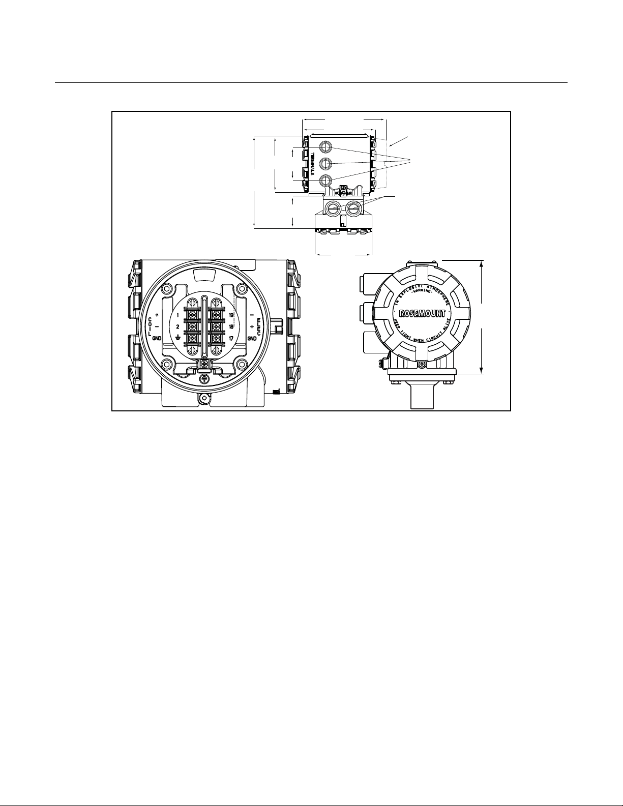
MECHANICAL CONSIDERATIONS
The mounting site for the 8732 transmitter should provide enough room for
secure mounting, easy access to conduit ports, full openin g of the transmitter
covers, and easy readability of the LOI screen (see Figure 2-1). The
transmitter should be mounted in a manner that prevent s moisture in conduit
from collecting in the transmitter.
If the 8732 is mounted remotely from the sensor, it is not subject to limitations
that might apply to the sensor.
2-2
Page 11
Reference Manual
5.82
(148)
6.48 (165)
7.49 (190)
LOI Cover
4.97
(126)
8.81
(224)
3.00
(76)
3.07
(78)
4.97
(126)
1
/2”-14 NPT Electrical
Conduit Connections
(2 places with a 3rd
optional)
1
/2”-14 NPT Remote Junction
Box Conduit Connections (2
places)
00809-0100-4665, Rev AA
August 2010
Figure 2-1. Rosemount 8732 Dimensional Drawing
Rosemount 8732
ENVIRONMENTAL CONSIDERATIONS
To ensure maximum transmitter life, avoid temperature extremes and
vibration. Typical problem areas include:
• high-vibration lines with integrally mounted transmitters
• warm-climate installations in direct sunlight
• outdoor installations in cold climates.
Remote-mounted transmitters may be installed in the control room to protect
the electronics from a harsh environment and provides easy access for
INSTALLATION PROCEDURES
configuration or service.
Rosemount 8732 transmitters require external power so there must be access
to a suitable power source.
Rosemount 8732 installation includes both detailed mecha nical and electrical
installation procedures.
Mount the Transmitter Remote-mounted transmitters may be mounted on a pipe up to two inches in
diameter or against a flat surface.
Pipe Mounting
To mount the transmitter on a pipe:
1. Attach the mounting bracket to the pip e using the m ounting har dware.
2. Attach the 8732 to the mounting bracket using the mounting screws.
2-3
Page 12

Rosemount 8732
Reference Manual
00809-0100-4665, Rev AA
August 2010
Hardware
Jumpers/Switches
Conduit Ports and
Connections
The 8732 Profibus PA electronics board is equipped with two user-selectable
hardware switches. These switches do not have any functionality and should
be left in the default positions as listed below:
Simulate Enable OFF
Transmitter Security OFF
Changing the switch position will have no effect on the functionality of the
electronics.
Both the sensor and transmitter junction boxes have ports for 1/2-inch NPT
conduit connections, with optional CM20 and PG 13.5 adapter connections
available. These connections should be made in accordance with national,
local or plant electrical codes. Unused ports should be sealed with metal
plugs and PTFE tape or other thread sealant. Connections should also be
made in accordance with area approval requ ire m en ts, see example s be low
for details. Proper electrical installation is necessary to prevent errors due to
electrical noise and interference. Separate conduits are not necessary for the
coil drive and signal cables connecting the transmitter to the sensor, but a
dedicated conduit line between each transmitter and sensor is required. A
shielded cable must be used.
Example 1: Installing flanged sensors into an IP68 area. Sensors must be
installed with IP68 cable glands and cable to maintain IP68 rating. Unused
conduit connections must be properly sealed to prevent water ingress. For
added protection, dielectric gel can be used to pot the sensor terminal block.
Consult technical document 00840-0100-4750 when installing meters into an
IP68 installation.
Example 2: Installing flowmeters into explosion proof/flameproof areas.
Conduit connections and conduit must be rated for use in the hazardous area
to maintain flowmeter approval rating. Consult Appendix B: of this manual for
installation requirements for hazardous areas.
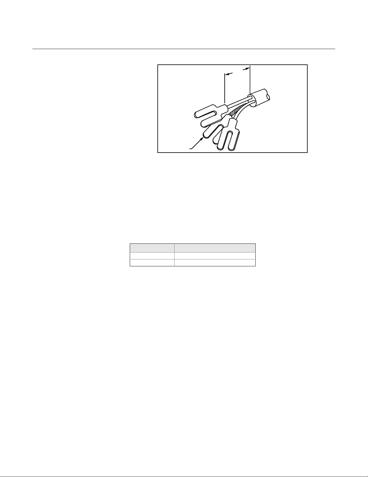
Conduit Cables Run the appropriate size cable through the conduit connections in your
magnetic flowmeter system. Run the power cable from the power source to
the transmitter . Do n ot run power cab les and outpu t signal cables in the same
conduit. For remote mount installations, run the coil drive and electrode
cables between the flowmeter and transmitter. Refer to Electrical
Considerations for wire type. Prepare the ends of the coil drive and electrode
cables as shown in Figure 2-2. Limit the unshielded wire length to 1-in. on
both the electrode and coil drive cables. Excessive lead length or failure to
connect cable shields can create electrical noise resulting in unstable meter
readings.
2-4
Page 13
Reference Manual
NOTE
Dimensions are in
inches
(millimeters).
1.00
(26)
Cable Shield
00809-0100-4665, Rev AA
August 2010
Rosemount 8732
Figure 2-2. Cable Preparation
Detail
Electrical Considerations Before making any electrical connections to the Rosemount 8732, consider
the following standards and be sure to have th e proper power supply, conduit,
and other accessories. When prepar ing all wir e conne ctions, remove only the
insulation required to fit the wire completely under the terminal connection.
Removal of excessive insulation may result in an unwanted electrical short to
the transmitter housing or other wire connections.
Transmitter Input Power
The 8732 transmitter is designed to be powered b y 90-250 V AC, 50–60 Hz or
12–42 V DC. The eighth digit in the transmitter model number designates the
appropriate power supply requirement.
Model Number Power Supply Requirement
1 90-250 V AC
2 12-42 V DC
Supply Wire Temperature Rating
Use 14 to 18 AWG wire rated for the proper temperatu re of the application.
For connections in ambient temperatures above 140 °F (60 °C), use a wire
rated for 176 °F (80 °C). For ambients greater than 176 °F (80 °C), use a
wire rated for 230 °F (110 °C). For DC powered transmitters with extended
power cable lengths, verify that there is a minimum of 12 Vdc at the
terminals of the transmitter.
Disconnects
Connect the device through an external disconnect or circuit breaker.
Clearly label the disconnect or circuit breaker and locate it near the
transmitter.
Requirements for 90-250 V AC Power Supply
Wire the transmitter according to national, local, and plant electrical
requirements for the supply voltage. In addition, follow the supply wire and
disconnect requirements on page2-6.
Requirements for 12-42 V DC Power Supply
Units powered with 12-42 V DC may draw up to 1 amp of cu rren t. As a result,
the input power wire must meet certain gauge requirements.
2-5
Page 14
Rosemount 8732
MaximumResis cetan
SupplyVoltage 12– VDC
1amp
--------------------------------------------------------------------=
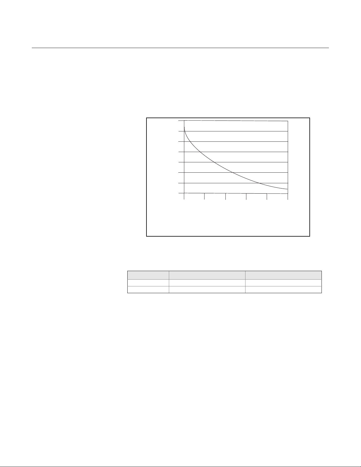
Power Supply (Volts)
I = 10/V
I = Supply current requirement (Amps)
V = Power supply voltage (Volts)
Supply Current (Amps)
12 18
24
30
36
42
0.2
0.3
0.4
0.5
0.6
0.7
0.8
0.9
Figure 2-3. Supply Current
versus Input Voltage
Reference Manual
00809-0100-4665, Rev AA
August 2010
Figure 2-3 shows the supply current for each corresponding supply voltage .
For combinations not shown, you can calculate the maximum distance given
the supply current, the voltage of the source, and the minimum start-up
voltage of the transmitter, 12 V DC, using the following equation:
Installation Category The installation category for the Rosemount 87 32 is (overvoltage) Category II.
Overcurrent Protection The Rosemount 8732 Flowmeter Transmitter requires overcurrent protection
of the supply lines. Maximum ratings of overcurrent devices are as follows:
Power System Fuse Rating Manufacturer
95-250 Vac 250 V; 2 Amp, Quick Acting Bussman AGCI or Equivalent
42 Vdc 50 V, 3 Amp, Qu ick Acting Bussman AGCI or Equivalent
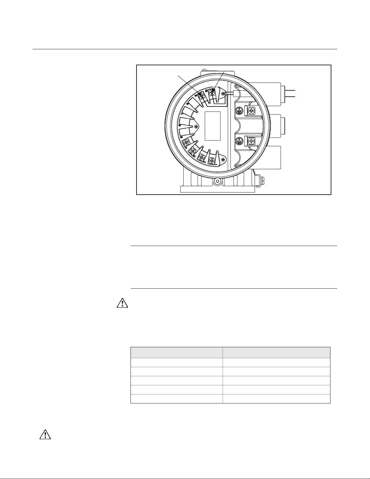
Connect Transmitter
Power
To connect power to the transmitter, complete the following steps.
1. Ensure that the power source and connecting cable meet the
requirements outlined on page 2-7.
2. Turn of f the power source.
3. Open the power terminal cover.
4. Run the power cable through the conduit to the transmitter.
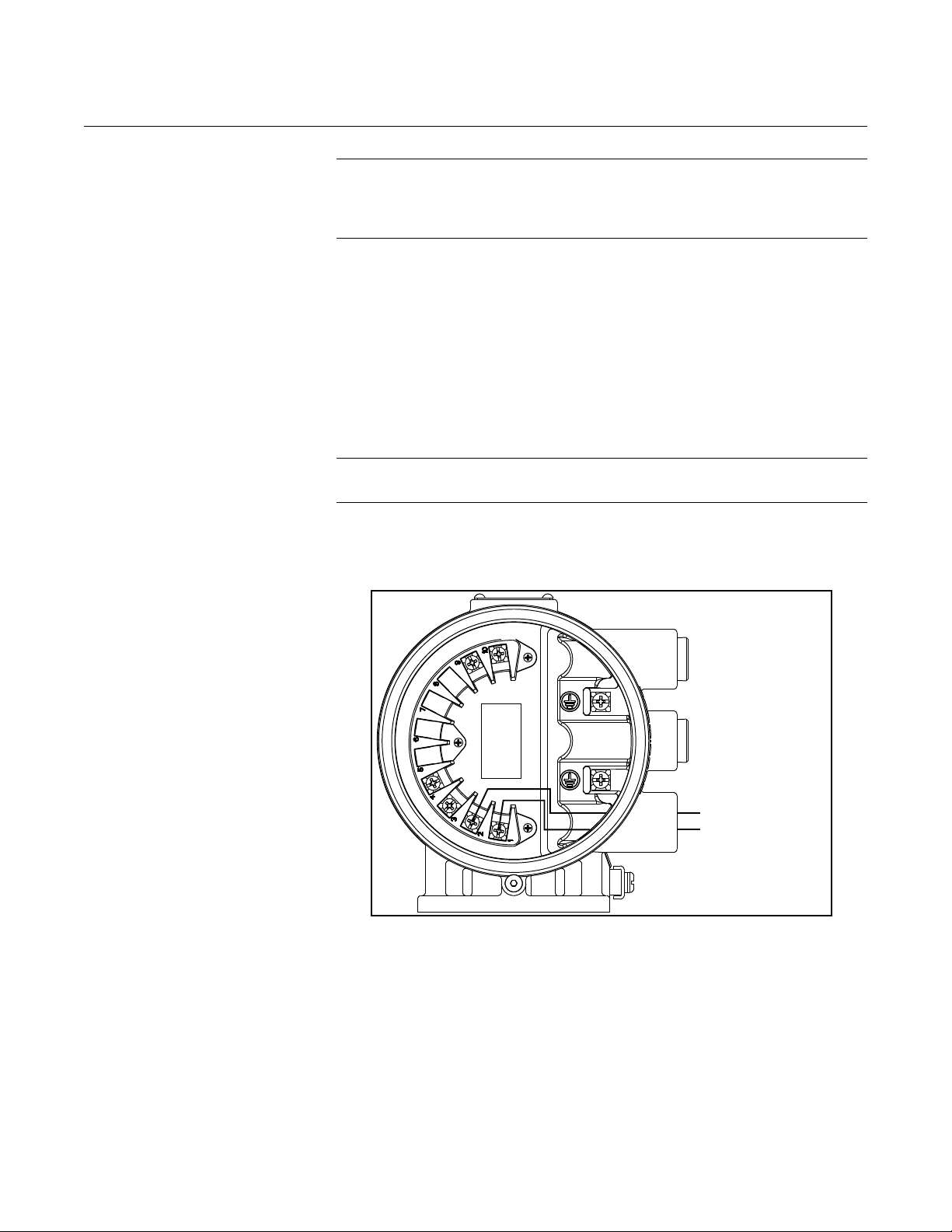
5. Connect the power cable leads as shown in Figure 2-4.
a. Connect AC Neutral or DC- to terminal 9.
b. Connect AC Line or DC+ to terminal 10.
c. Connect AC Ground or DC Ground to the ground screw mounted
inside the transmitter enclosure.
2-6
Page 15
Reference Manual
AC Line or DC +
Transmitter
Power Cable
AC Neutral or DC –
AC or DC
Ground
See “Safety Messages” on page 2-1 for complete warning information.
00809-0100-4665, Rev AA
August 2010
Figure 2-4. AC Transmitter
Power Connections
Rosemount 8732
Connect Profibus PA
Wiring
Transmitter
Communication Input
Field Wiring Power independent of the coil power supply must be supplied for Profibus PA
Table 2-1.
Ideal Cable Specifications for
Profibus Wiring
The Profibus PA signal provides the output information from the transmitter.
The Profibus PA communication requires a minimum of
9 V dc and a maximum of 32 V dc at the transmitter communication terminals.
NOTES
• Do not exceed 32 V dc at the transmitter communication terminals.
• Do not apply ac line voltage to the transmitter
communication terminals.
Improper supply voltage can damage the transmitter.
communications. Use shielded, twisted pair for best results. For new
installations or to get maximum performance, twisted pair cable designed
especially for Profibus should be used. Table 2-1 details cable characteristics
and ideal specifications.
Characteristic Ideal Specification
Impedance 135 to 165 (150 Nominal)
Wire Size 22 AWG (0,34 mm2)
Shield Coverage 90%
Loop Resistance < 110 /km
Capacitance < 30 pF/km
2-7
Page 16
Rosemount 8732
PA signal
PA signal
Reference Manual
00809-0100-4665, Rev AA
August 2010
NOTE
The number of devices on a Profibus segment is limited by the power supply
voltage, the resistance of the cable, and the amount of current drawn by
each device.
Transmitter Wiring
Connection
Figure 2-5. Profibus PA Signal
Connections
To connect the 8732 to the Profibus PA segment, complete the following
steps.
1. Ensure that the power source and connecting cable meet the
requirements outlined above and in “Field Wiring” on page 2-7.
2. Turn of f the transmitter and power sources.
3. Run the Profibus PA cable into the transmitter.
4. Connect PA to Terminal 1.
5. Connect PA to Terminal 2.
NOTE
Profibus PA signal wiring for the 8732 is not polarity sensitive.
Refer to Figure 2-5 on page 2-8.
2-8
Page 17
Reference Manual
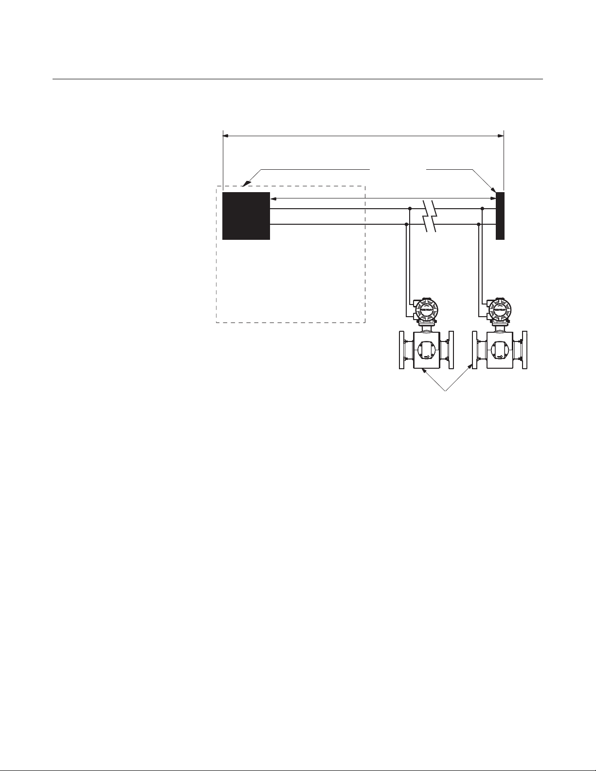
(Trunk)
(Spur)
Terminators
(The power supply,
filter, first terminator,
and configuration tool
are typically located in
the control room.)
Devices 1 through 11*
* Intrinsically safe installations may
allow fewer devices per I.S. barrier.
Profibus DP
to Profibus
PA Convertor
(Spur)
6234 ft (1900 m) max
(depending upon cable characteristics)
00809-0100-4665, Rev AA
August 2010
Figure 2-6. Rosemount 8732
Transmitter Field Wiring
Rosemount 8732
2-9
Page 18
Reference Manual
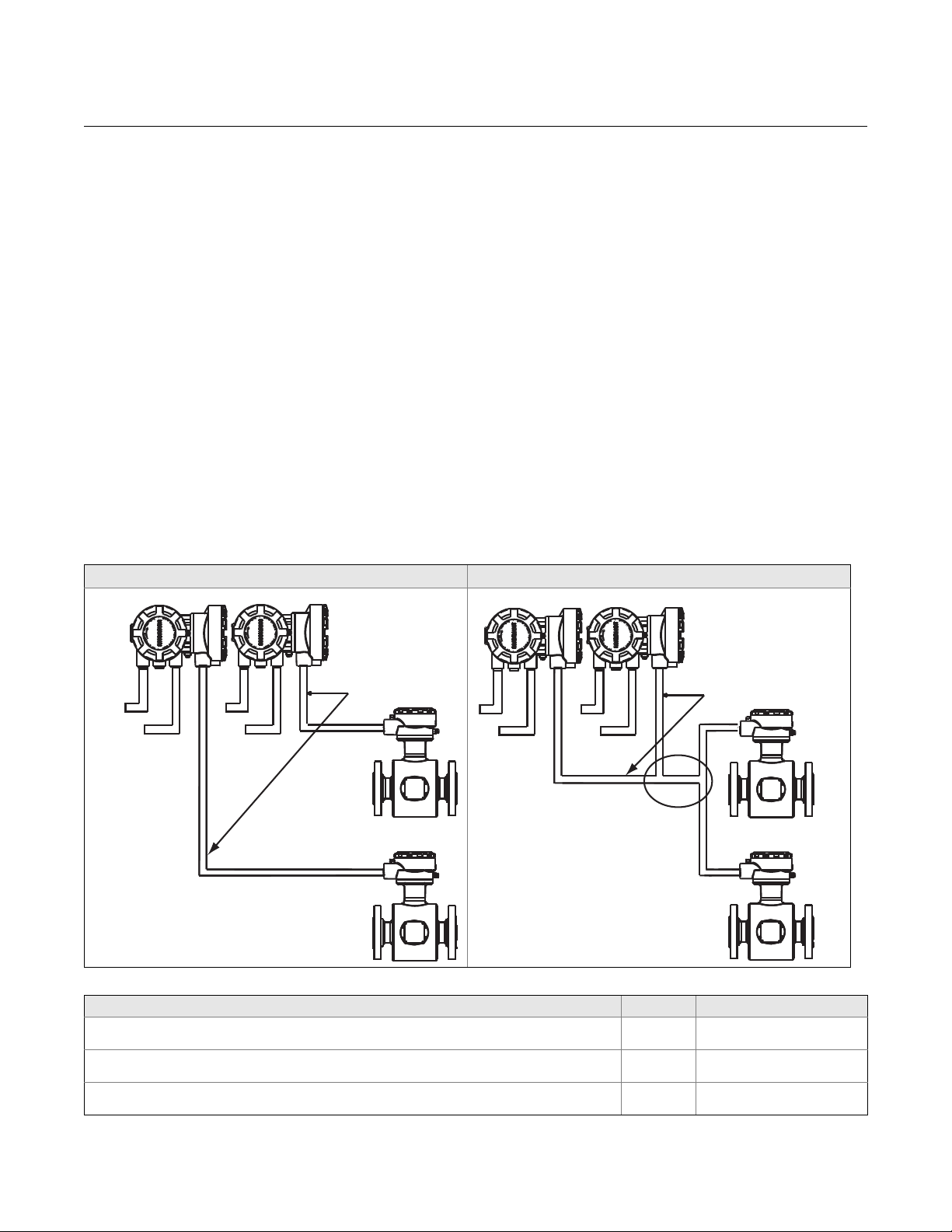
Coil Drive
and
Electrode
Cables
Power
Power
Outputs
Outputs
Coil Drive
and
Electrode
Cables
Power
Outputs
Power
Outputs
00809-0100-4665, Rev AA
Rosemount 8732
August 2010
SENSOR CONNECTIONS This section covers the steps required to physically install the transmitter
including wiring and calibration.
Rosemount Sensors To connect the transmitter to a non-Rosemount sensor, refer to the
appropriate wiring diagram in “Universal Sensor Wiring Diagrams” on
page E-1. The calibration procedure listed is not required for use with
Rosemount sensors.
Transmitter to Sensor
Wiring
Figure 2-7. Conduit Preparation
Correct Incorrect
Flanged and wafer sensors have two conduit ports as shown in Figur e 2-7.
Either one may be used for both the coil drive and electrode cables. Use the
stainless steel plug that is provided to seal the unused conduit port. Use
PTFE tape or thread sealant appropriate for the installation when sealing the
conduit.
A single dedicated conduit run for the coil drive and electrode cables is
needed between a sensor and a remote transmitter. Bundled cables in a
single conduit are likely to create interference and noise problems in your
system. Use one set of cables per conduit run. See Figure 2-7 for proper
conduit installation diagram and Table 2-2 for recommended cable. For
integral and remote wiring diagrams refer to Figure 2-9.
Table 2-2. Cable Requirements
Description Units Part Number
Signal Cable (20 AWG) Belden 8762, Alpha 2411 equivalent ft
Coil Drive Cable (14 AWG) Belden 8720, Alpha 2442 equivalent ft
Combination Signal and Coil Drive Cable (18 AWG)
(1) Combination signal and coil drive cable is not recommended for high-signal magmeter system. For remote mount installations, combinat ion signal and coil
2-10
(1)
drive cable should be limited to less than 330 ft. (100 m).
08712-0061-0001
m
m
ft
m
08712-0061-2003
08712-0060-0001
08712-0060-2003
08712-0752-0001
08712-0752-2003
Page 19
Reference Manual
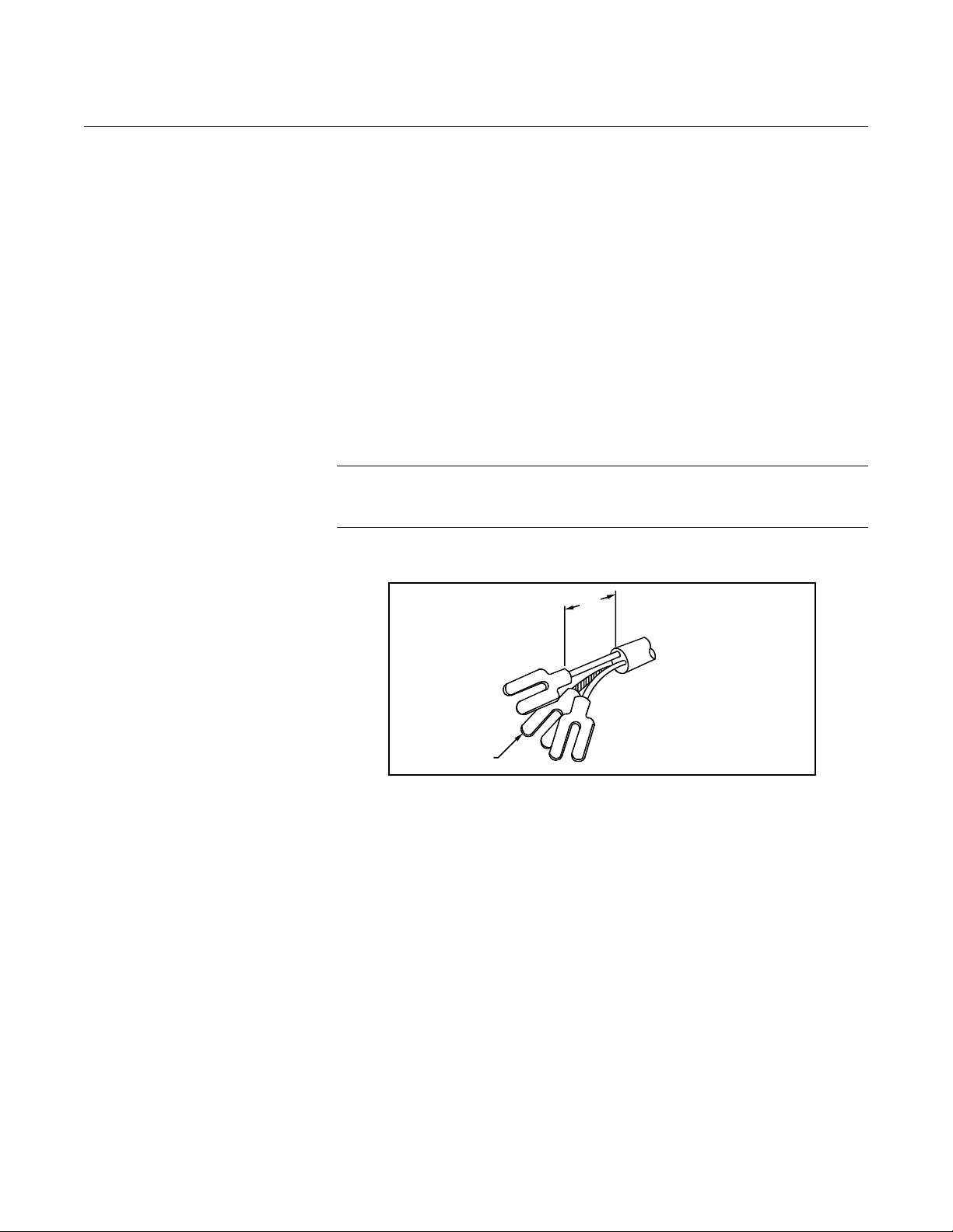
1.00
(26)
NOTE
Dimensions are in
inches (millimeters).
Cable Shield
00809-0100-4665, Rev AA
August 2010
Rosemount 8732
Rosemount recommends using the combination signal and coil drive for N5,
E5 approved sensors for optimum performance.
Remote transmitter installations require equal lengths of signal and coil drive
cables. Integrally mounted transmitters are factory wired and do not require
interconnecting cables.
Lengths from 5 to 1,000 feet (1.5 to 300 meters) may be specified, and will be
shipped with the sensor.
Conduit Cables Run the appropriate size cable through the conduit connections in your
magnetic flowmeter system. Run the power cable from the power source to
the transmitter. Run the coil drive and electrode cables between the sensor
and transmitter .
Prepare the ends of the coil drive and electrode cables as shown in Figure
2-8. Limit the unshielded wire length to 1-inch on both the electrode and coil
drive cables.
NOTE
Excessive lead length or failure to connect cable shields ca n create electrical
noise resulting in unstable meter readings.
Figure 2-8. Cable Preparation
Detail
2-11
Page 20
Rosemount 8732
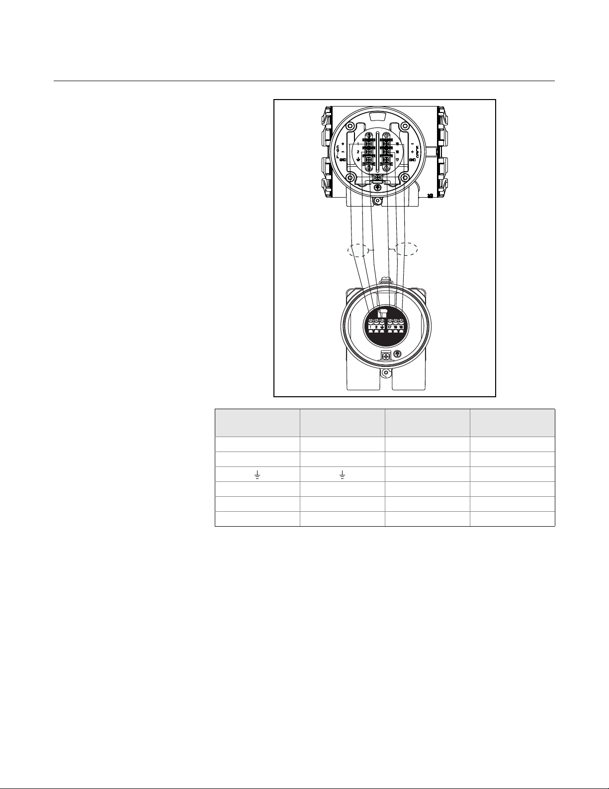
Figure 2-9. Wiring Diagram
Reference Manual
00809-0100-4665, Rev AA
August 2010
Transmitter
Terminal
1 1 14 Clear or Red
2 2 14 Black
17 17 20 Shield
18 18 20 Black
19 19 20 Clear or Red
Sensor Terminal Wire Gauge Wire Color
14 Shield
2-12
Page 21

Reference Manual
00809-0100-4665, Rev AA
August 2010
Rosemount 8732
Section 3 Configuration
Quick Start-Up . . . . . . . . . . . . . . . . . . . . . . . . . . . . . . . . . . .page 3-1
Assigning Device Tag and Node Address . . . . . . . . . . . .page 3-2
Basic Setup . . . . . . . . . . . . . . . . . . . . . . . . . . . . . . . . . . . . . page 3-2
This section covers basic operation, software functionality, and basic
configuration procedures for the Rosemount 8732E Magnetic Flowmeter
Transmitter with Profibus PA. For more information about the Profibus PA
technology and the function blocks used in the transmitter, refer to
Appendix F: Physical Block and Appendix G.
Calibration Rosemount sensors are wet calibrated at the factory. They do not need
further calibration during installation.
Each Profibus PA configuration tool or host device has a different way of
displaying and performing configurations. Some will use Device Descriptions
(DD) and DD Methods to make configuring and displaying data consistent
across host platforms. There is no requirement that a configuration tool or
host support these features. This section describes how to reconfigure the
device manually.
QUICK START-UP Once the magnetic flowmeter system is installed and communication is
established, configuration of the transmitter must b e completed. The st andard
transmitter configuration, without Option Code C1, Custom Configuration, is
shipped with the following parameters:
Engineering Units: ft/s
Sensor Size: 3-in.
Sensor Calibration Number: 100000501000000
Sensor
Calibration Number
A unique sensor calibration number, imprinted on the sensor tag, enables any
Rosemount sensor to be used with any Rosemount transmitter without further
calibration. Rosemount flow lab tests determine individual sensor output
characteristics. The characteristics are identified by a 16-digit calibration
number . In a Profibus PA environment, the 8732E can be configured using an
8732E Profibus P A LOI or a Simatic PDM. Please see Section 4 for 8732E PA
LOI and PDM information.
www.rosemount.com
Page 22

Rosemount 8732
Reference Manual
00809-0100-4665, Rev AA
August 2010
The calibration number is more than a correction factor, or K- factor, for the
sensor. The first five digits represent the low frequency gain. The ninth
through thirteenth digits represent the high frequency ga in. Both nu mbers are
normalized from an ideal number of 10000. Standard configurations use the
low frequency gain, but in noisy applications it may be worthwhile to switch to
the higher frequency. An additional transmitter procedure, called Auto Zero, is
recommended to perform at the higher coil drive frequency. The seventh and
eighth digits represent the zero offset at both frequencies where the nominal
value is 50. Empty pipe functionality is a transmitter feature that is controlled
by a parameter in the transducer block. To turn off this feature, see
Appendix C.
ASSIGNING DEVICE T AG AND NODE ADDRESS
The 8732E Magnetic Flowmeter Tr ansmitter is shipped with a blank tag. The
device is shipped with a default address of 126.
If the tag or address needs to be changed, use the features of the
configuration tool. The tools do the following:
• Change the tag to a new value.
• Change the address to a new address.
BASIC SETUP
AI Block The Analog Input (AI) function block processes field device measurements
and makes them available to the master. The output value from the AI block is
in engineering units and contains a status indi cating the quality of the
measurement. The measuring device may have several measurements or
derived values available in different channels. Use the channel number to
define the variable that the AI block processes. The 8732E transmitter only
supports “Flow” as AI Block variable.
3-2
Page 23

Reference Manual
00809-0100-4665, Rev AA
August 2010
Rosemount 8732
AI Block Parameter
Attribute Definitions
The following table describes the parameters that are available in the analog
input function block. Each line item in the table defines the element and
specifies the requirements for each element.
Absolute
Index
Profibus PA Specific Block
16 BLOCK_OBJECT This object contains the characteristics of the
17 ST_REV The modification of at least one static parameter in
18 TAG_DESC Every block can be assigned a textual TAG
19 STRATEGY Grouping of Function Block. The STRATEGY field
20 ALERT_KEY This parameter contains the identification number
21 TARGET_MODE The TARGET_MODE parameter contains desired
22 MODE_BLK This parameter contains the current mode, the
23 ALARM_SUM This parameter contains the current states of the
24 BATCH This parameter is intended to be used in Batch
25 RESERVED by PNO
26 OUT The Function Block parameter OUT contains the
27 PV_SCALE Conversion of the Process Variable into percent
28 OUT_SCALE Related to the PV_UNIT of the configured
29 LIN_TYPE Type of linearization. The 8732E only supports “No
30 CHANNEL Reference to the active Transducer Block which
31 RESERVED
32 PV_FTIME Filter time of the Process Variable.
Parameter Description
Header
blocks.
a block has to be incremented by the according
ST_REV at least by one.
description. The TAG_DESC must be unambiguous
and unique in the fieldbus system.
can be used to group blocks.
of the plant unit. It helps to
identify the location (plant unit) of an event.
mode normally set by a control application or an
operator. The modes are valid alternatively only,
i.e. only one mode can be set at one time. A write
access to this parameter with more then one mode
is out of the range of the parameter and have to be
refused.
permitted and normal mode of the block.
block alarms.
applications. Not implemented in 8732E device.
current measurement value in a vendor specific or
configuration adjusted engineering unit and the
belonging state in AUTO MODE. The Function
Block parameter OUT contains the value and status
set by an operator in MAN MODE.
using the high and low scale values. The
engineering unit of PV_SCALE high and low scale
values are directly.
Transducer Block (configured via Channel
parameter). The PV_SCALE high and low scale
values follow the mapped to last 16 characters of
DEVICE_ID_STRING parameter in Mfg. Block.
linearization”.
provides the measurement value
to the Function Block.
3-3
Page 24

Rosemount 8732
Reference Manual
00809-0100-4665, Rev AA
August 2010
Absolute
Index
33 FSAFE_ TYPE Defines the reaction of device, if a fault is detected.
34 FSAFE_VALUE Default value for the OUT parameter, if a sensor or
35 ALARM_HYS Within the scope of the PROFIBUS-PA specification
36 RESERVED
37 HI_HI_LIM Value for upper limit of alarms
38 RESERVED
39 HI_LIM Value for upper limit of warnings
40 RESERVED
41 LO_LIM Value for lower limit of warnings
42 RESERVED
43 LO_LO_LIM Value for the lower limit of alarms
44 RESERVED
45 RESERVED
46 RESERVED
47 RESERVED
48 RESERVED
49 RESERVED
50 SIMULATE For commissioning and test purposes the input
51-60 RESERVED BY PNO
61 VIEW_1_AI
Parameter Description
The calculated ACTUAL MODE remains in AUTO.
0: value FSAFE_VALUE is used as OUT
Status - UNCERTAIN_Substitute Value,
1: use last stored valid OUT value
Status - UNCERTAIN_LastUsableValue
if there is no valid value available, then
UNCERTAINInital_Value, OUT value is = Initial
value
2: OUT has the wrong calculated value and status
Status - BAD_* (* as calculated)
sensor electronic fault is detected. The unit of this
parameter is the same as the OUT parameter.
for transmitters there are functions for the
monitoring of limit violation (off-limit conditions) of
adjustable limits. Maybe the value of one process
variable is just the same as the value of a limit and
the variable fluctuates around the limit it will occur a
lot of limit violations. That triggers a lot of
messages; so it must be possible to trigger
messages only after crossing an adjustable
hysteresis. The sensitivity of triggering of the alarm
messages is adjustable. The value of the hysteresis
is fixed in ALARM_HYS and is the same for the
parameters HI_HI_LIM, HI_LIM, LO_LIM and
LO_LO_LIM. The hysteresis is expressed as value
below high limit and above low limit in the
engineering unit of xx_LIM.
value from the Transducer Block in the Analog Input
Function Block AI-FB can be modified. That means
that the Transducer and AI-FB will be disconnected.
3-4
Page 25

Reference Manual
00809-0100-4665, Rev AA
August 2010
Totalizer Block Totalizer 1 is Slot 2
Totalizer 2 is Slot 3
Totalizer 3 is Slot 4
The 8732E transmitter has three independent totalizer blocks. These blocks
can be used to totalize independently over different time ranges or using
different units of measure.
Rosemount 8732
Totalize Block Parameter
Attribute Definitions
The following table describes the p arameters that ar e available in the tot alizer
(INTEG) block. Each line item in the table defines the element and specifies
the requirements for each element.
Index Parameter Description
Profibus PA Specific Block
Header
16 BLOCK_OBJECT This object contains the characteristics of the
blocks.
17 ST_REV The modification of at least one static parameter
in a block has to be incremented by the
according ST_REV at least by one.
18 TAG_DESC Every block can be assigned a textual TAG
description. The TAG_DESC must be
unambiguous and unique in the fieldbus
system.
19 STRATEGY Grouping of Function Block. The STRATEGY
field can be used to group blocks.
20 ALERT_KEY This parameter contains the identification
number of the plant unit. It helps to
identify the location (plant unit) of an event.
21 TARGET_MODE The TARGET_MODE parameter contains
desired mode normally set by a control
application or an operator. The modes are valid
alternatively only, i.e. only one mode can be set
at one time. A write access to this parameter
with more then one mode is out of the range of
the parameter and have to be refused.
22 MODE_BLK This parameter contains the current mode, the
permitted and normal mode of the block.
23 ALARM_SUM This parameter contains the current states of
the block alarms.
24 BATCH This parameter is intended to be used in Batch
applications. Not implemented in 8732E device.
25 RESERVED
3-5
Page 26

Rosemount 8732
Reference Manual
00809-0100-4665, Rev AA
August 2010
Profibus PA specific
Parameters
26 TOTAL The Function Block parameter TOTAL contains
the integrated quantity of the rate parameter
provided by CHANNEL and the associated
status.
27 UNIT_TOT Unit of the totalized quantity.
28 CHANNEL Reference to the active Transducer Block,
which provides the measurement value to the
Function Block.
29 SET_TOT The following selections of this Function Block
parameter are possible:
0: TOTALIZE; “normal“ operation of the Totalizer
1: RESET; assign value “0“ to Totalizer
2: PRESET; assign value of PRESET_TOT to
Totalizer
30 MODE_TOT 0: BALANCED; true arithmetic integration of the
incoming rate values.
1: POS_ONLY; totalization of positive incoming
rate values only.
2: NEG_ONLY ; tot alization of negative incoming
rate values only.
3: HOLD; totalization stopped
31 FAIL_TOT 0: RUN; totalization is continued using the input
values despite the BAD status.
The status is ignored.
1: HOLD; totalization is stopped during
occurrence of BAD status of incoming
values.
2: MEMORY; totalization is continued based on
the last incoming value
with GOOD status before the first occurrence of
BAD status.
32 PRESET_TOT This value is used as a preset for the internal
value of the FB algorithm. The value is effective
if using the SET_TOT function.
33 ALARM_HYS Within the scope of the PROFIBUS-PA
specification for transmitters there are
functions for the monitoring of limit violation
(off-limit conditions) of adjustable limits.
Maybe the value of one process variable is just
the same as the value of a limit and the variable
fluctuates around the limit it will occur a lot of
limit violations. That triggers a lot of messages;
so it must be possible to trigger messages only
after crossing an adjustable hysteresis. The
sensitivity of triggering of the alarm messages is
adjustable. The value of the hysteresis is fixed
in ALARM_HYS and is the same for the
parameters HI_HI_LIM, HI_LIM, LO_LIM and
LO_LO_LIM. The hysteresis is expressed as
value below high limit and above low limit in the
engineering unit of xx_LIM.
34 HI_HI_LIM Value for upper limit of alarms
35 HI_LIM Value for upper limit of warnings
36 LO_LIM Value for lower limit of warnings
37 LO_LO_LIM Value for the lower limit of alarms
38 - 51 RESERVED BY PNO
52 VIEW_1_TOT
3-6
Page 27

Reference Manual
00809-0100-4665, Rev AA
August 2010
Rosemount 8732
TR ANSDUCER BLOCK
PV The process variables (PV) measure flow in several ways that reflect your
needs and the configuration of your flowmeter. When commissioning a
flowmeter, review each process variable, its function and output, and take
corrective action if necessary before using the flowmeter in a
process application
PV Value – The actual measured flow rate in the line. Use the Process
Variable Units function to select the units for your application.
PV Status – The status of the pr ocess variable. This indicates whether the
reported flow rate is “good”, “uncertain”, or “bad”.
PV Value The PV Value shows the current measured flow rate.
PV Status The PV Status shows the health of the PV Value.
Good - The PV Value is valid an d th e flo wmeter system is operating normally.
Uncertain - The PV Value is being reported, but a condition exists that is
potentially compromising the measurement. This condition could be caused
by a problem with the flowmeter or the process.
Bad - A problem exists with the flowmeter system that has resulted in a
potentially faulty flow measurement. Consult status and diagnostic
information to identify the problem.
BASIC SETUP The basic configuration functions of the Rosemount 8732 must be set for all
applications of the transmitter in a magnetic flowmeter system. If your
application requires the advanced functionality features of the Rosemount
8732, see Section 4 of this manual.
Flow Units Flow Units set the output units for the Primary Variable. This parameter is
configured in the Transducer Block.
3-7
Page 28

Rosemount 8732
Reference Manual
00809-0100-4665, Rev AA
August 2010
Options for Flow Rate Units
• ft/s • bbl/s (1 Barrel = 42 gallons)
• ft/m • bbl/min (1 Barrel = 42 gallons)
• ft/h • bbl/h (1 Barrel = 42 gallons)
•m/s • bbl/d (1 Barrel = 42gallons)
•m/h •cm3/s
• gal/s •cm3/min
•GPM •cm3/h
• gal/h •cm3/d
• gal/d •lb/s
•L/s •lb/min
•L/min •lb/h
•L/h •lb/d
•L/d •kg/s
•CFS •kg/min
•CFM •kg/h
•CFH •kg/d
•ft3/d • STon/s
•m3/s • STon/min
•m3/min • STon/h
•m3/h • STon/d
•m3/d • t/s
•IGAL/s • t/min
•IGAL/min • t/h
•IGAL/h • t/d
•IGAL/d • BBL/s (1 Barrel = 31 gallons)
• BBL/m (1 Barrel = 31 gallons)
• BBL/h (1 Barrel = 31 gallons)
• BBL/d (1 Barrel = 31 gallons)
Line Size The line size (sensor size) must be set to match the actual sensor connected
to the transmitter. The size must be specified in inches according to the
available sizes listed below. If a value is entered from a control system that
does not match one of these figures, the value will go to the next highest
option. This parameter is configured in the Transducer Block.
The line size (inches) options are as follows:
0.1, 0.15, 0.25, 0.30, 0.50, 0.75, 1, 1.5, 2, 2.5, 3, 4, 6, 8, 10, 12, 14,
16, 18, 20, 24, 28, 30, 32, 36, 40, 42, 44, 48, 54, 56, 60, 64, 72, 80
3-8
Page 29

Reference Manual
00809-0100-4665, Rev AA
August 2010
Rosemount 8732
Upper Range Value This parameter set the flow rate in engineering units that corresponds to
100% flow. This parameter is configured in the Transducer Block.
The Upper Range Value can be set for both forward or reverse flow rates.
Flow in the forward direction is represented by positive values and flow in the
reverse direction is represented by negative values. The URV can be any
value from –43.3 ft/s to +43.3 ft/s (-13.2 m/s to +13.2 m/s), as long as it is at
least 1 ft/s (0.3 m/s) from the lower range value (LRV). The URV can be set to
a value less than the lower range value.
NOTE
Line size and density must be selected prior to configuration of URV and LRV .
Lower Range Value This parameter sets the flow rate in engineering units that correspo nds to 0%
flow. This pa rameter is configured in the Transducer Block.
Set the lower range value (LRV) to change the size of the range (or span)
between the URV and LRV. Under normal circumstances, the LRV should be
set to a value near the minimum expected flow rate to maximize resolution.
The LRV must be between –43.3 ft/s to +43.3 ft/s (-13.2 m/s to +13.2 m/s).
NOTE
Line size and density must be selected prior to configuration of URV and LR V.
The minimum allowable span between the URV and LRV is 1 ft/s (0.3 m/s).
Do not set the LRV within 1 ft/s (0.3 m/s) of the URV. For example, if the URV
is set to 15.67 ft/s (4.8 m/s) and if the desired URV is greater than the LRV,
then the highest allowable LRV setting would be 14.67 ft/s (4.5 m/s). If the
desired URV is less than the LRV, then the lowest allowable LRV would be
16.67 ft/s (5.1 m/s).
Calibration Number The sensor calibration number is a 16-digit number used to identify sensors
calibrated at the Rosemount factory. The calibration number is also printed
inside the sensor terminal block or on the sensor name plate. The number
provides detailed calibration information to the Rosemount 8732. To function
properly within accuracy specifications, the number stored in the transmitter
must match the calibration number on the sensor exactly. This parame te r is
configured in the Transducer Block.
NOTE
Sensors from manufacturers other than Rose m ou nt Inc. can als o be
calibrated at the Rosemount factory. Check the sensor for Rosemount
calibration tags to determine if a 16-digit sensor calibration number exists for
your sensor.
3-9
Page 30

Reference Manual
00809-0100-4665, Rev AA
Rosemount 8732
NOTE
Be sure the calibration number reflects a calibration to a Rosemount
reference transmitter. If the calibration number was generated by a means
other than a certified Rosemount flow lab, accuracy of the system may be
compromised.
If your sensor is not a Rosemount sensor and was not calibrated at the
Rosemount factory, contact your Rosemount representative for assistance.
If your sensor is imprinted with an eight-digit number or a k-factor, check in
the sensor wiring compartment for the sixteen-digit calibration number. If
there is no serial number, contact the factory for a proper conversion.
August 2010
Damping Adjustable between 0.0 and 256 seconds. This parameter is configured in the
Transducer Blo ck.
Damping allows selection of a response time, in seconds, to a step change in
flow rate. It is most often used to smooth fluctuations in output.
3-10
Page 31

Reference Manual
00809-0100-4665, Rev AA
August 2010
Rosemount 8732
Section 4 Operation
Introduction . . . . . . . . . . . . . . . . . . . . . . . . . . . . . . . . . . . . . page 4-1
Local Operator Interface . . . . . . . . . . . . . . . . . . . . . . . . . .page 4-1
Diagnostics . . . . . . . . . . . . . . . . . . . . . . . . . . . . . . . . . . . . . page 4-3
Advanced Configuration . . . . . . . . . . . . . . . . . . . . . . . . . .page 4-12
Detailed Setup . . . . . . . . . . . . . . . . . . . . . . . . . . . . . . . . . . .page 4-12
INTRODUCTION This section contains information for advanced configuration parameters and
diagnostics.
The software configuration settings for the Rosem ount 8732 can be accessed
through an 8732 LOI or by using a Class 2 Master. Before operating the
Rosemount 8732 in an actual installation, you should review all of the factory
set configuration data to ensure that they reflect the current application.
LOCAL OPERATOR INTERFACE
The optional Local Operator Interface (LOI) provides an operator
communications centre for the 8732. By using th e LO I, th e op er at or can
access some of the transmitter function - totalizer, basic set-up, or other
functions under the detailed set-up. The LOI is integral to the transmitter
electronics. If you need the added functio nality, or if your transmitter does not
have an LOI, you must use a configuration tool such as the Simatic PDM tool.
Basic Features
The basic features of the LOI include 4 navigational arrow keys which are
optical switches that are used to access the menu structure. See Figure
below:
www.rosemount.com
Page 32

Rosemount 8732
Reference Manual
00809-0100-4665, Rev AA
August 2010
Data Entry
The LOI keypad does not have numerical keys. Numerical data is entered by
the following procedure.
1. Access the appropriate function.
2. Use the RIGHT ARROW key to move to the value to change.
3. Use the UP and DOWN ARROWS to change the highlighted value.
For numerical data, toggle throug h the digit s 0–9 , decimal point, and
dash. For alphabetical data, toggle through the letters of the alphabet
A–Z, digits 0–9, and the symbols _,&, +, -, *, /, $, @,%, and the bla nk
space.
4. Use the RIGHT ARROWS to highlight other digits you want to change
and change them.
5. Press “E” (the left arrow key) when all changes are complete to save
the entered values.
LOI Language
This allows you to configure the language shown on the display. There are
five options available:
• English
• Spanish
• Portuguese
•German
•French
LOI Menu Tree
Totalizers
Basic Setup
Detailed Setup
Totalizer 1
Totalizer 2
Totalizer 3
Flow Units
Sensor Size
Cal Number
Damping
Coil Frequency
Profibus
AI Block Conf
LOI Config
Trims
8714i
Run 8714i
View Results
TubeSignature
Measurements
Total 3 Value
Tota l 3 Config
Device Address
Ident Selector
Total 3 Set
Total 3 Mode
Total 3 Units
Total 3 Preset
AI PV Scale
AI Out Scale
Display Timing
Language
Write Lock
Auto Zero Trim
Universal Trim
Values
Re-signature
Recall Values
T otal 1Value
Total 1 Config
Total 2 Value
Total 2 Config
PV Scale URV
Out Scale LRV
PV
Totalizer 1
Totalizer 2
Totalizer 3
Total 1 Set
Total 1 Mode
Total 1 Units
Total 1 Preset
Total 2 Set
Total 2 Mode
Total 2 Units
Total 2 Preset
Out Scale Unit
Out Scale URV
Out Scale LRV
Coil Resist
Coil Signature
Electrode Res
4-2
Coil Resist
Coil Signature
Electrode Res
Page 33

Reference Manual
00809-0100-4665, Rev AA
August 2010
Rosemount 8732
Class 2 Masters There are a number of available PROFIBUS configuration tools. These Class
2 Masters are manufacturer-independent tools for the operation,
configuration, maintenance, and diagnosis of intelligent field devices. Device
descriptor based Class 2 Masters allow 100% configuration capability on the
8732E Profibus PA transmitter.
Class 2 Masters always need to be connected to the DP segment. They
cannot be directly connected to a PA segment.
DIAGNOSTICS Diagnostics are used to verify that the transmitter is functioning properly, to
assist in troubleshooting, to identify potential causes of error messages, and
to verify the health of the transmitter and sensor. All the diagnostic test can be
initiated through the use of a Class 2 Master. Some diagnostics can be
accessed using the LOI.
Rosemount offers several different diagnostic suites providing various
functionality.
Standard diagnostics included with every Rosemount 8732 transmitter are
Empty Pipe detection, Electronics Temperature monitoring, Coil Fault
detection, and various loop and transmitter tests.
Advanced diagnostics suite option one (D01 option) contains advanced
diagnostics for High Process Noise detection and Grounding and Wiring fault
detection.
Advanced diagnostics suite option two (D02 option) contains advanced
diagnostics for the 8714i Meter Verification. This diagnostic is used to verify
the accuracy and performance of the magnetic flow meter installation.
Empty Pipe Detection
Turn the empty pipe diagnostic on or off as required by the application. For
more details on the empty pipe diagnostic, see Appendix C: Diagnostics.
Electronics Temperature Out of Range
Turn the electronics temperature diagnostic on or off as required by the
application. For more details on the electronics temperature diagnostic, see
Appendix C: Diagnostics.
High Process Noise Detection
Turn the high process noise diagnostic on or off as required by the
application. For more details on the high process noise diagn os tic , see
Appendix C: Diagnostics.
Grounding / Wiring Fault Detection
Turn the grounding / wiring diagnostic on or of f as required by the application .
For more details on the grounding / wiring diagnostic, see Appendix C:
Diagnostics.
4-3
Page 34

Reference Manual
00809-0100-4665, Rev AA
Rosemount 8732
August 2010
Basic Diagnostics The basic diagnostics menu contains all of the standard dia gnostics and test s
that are available in the 8732E transmitter.
Empty Pipe Limits
Empty Pipe allows you to view the current value and configure the diagnostic
parameters. For more detail on this parameter see Appendix C: Diagnostics.
EP Value
Read the current Empty Pipe Value. This number is a unitless number and is
calculated based on multiple installation and process variables. For more
detail on this parameter see Appendix C: Diagnostics.
EP Trigger Level
Limits: 3 to 2000
Configure the threshold limit that the empty pipe value must exceed before
the diagnostic alert activates. Default from the factory is set to 100. For more
detail on this parameter see Appendix C: Diagnostics.
EP Counts
Limits: 5 to 50
Configure the number of consecutive times that the empty pipe value must
exceed the empty pipe trigger level before the diagnostic alert activates.
Counts are taken at 1.5 second intervals. Default from the factory is set to 5.
For more detail on this parameter see Appendix C: Diagnostics.
Electronics Temp Value
Electronics Temperature allows you to view the current value for the
electronics temperature.
Advanced Diagnostics The advanced diagnostics menu contains information on all of the additional
diagnostics and tests that are available in the 8732 transmitter if one of the
diagnostics suite packages was ordered.
Rosemount offers two advanced diagnostic suites. Functionality under this
menu will depend on which of these suites are ordered.
Advanced diagnostics suite option one (D01 option) contains advanced
diagnostics for High Process Noise detection and Grounding and Wiring fault
detection.
Advanced diagnostics suite option two (D02 option) contains advanced
diagnostics for the 8714i Meter Verification. This diagnostic is used to verify
the accuracy and performance of the magnetic flow meter installation.
8714i Meter Verification
4-4
This diagnostic allows you to test and verify that the sensor, transmitter, or
both are working within specifications. For more details on this diagnostic, see
Appendix C: Diagnostics.
Page 35

Reference Manual
00809-0100-4665, Rev AA
August 2010
Rosemount 8732
Run 8714i
Run the meter verification test to check the transmitter, sensor, or entire
installation.
Full Meter Verification
Run the internal meter verification to check the entire installation, sensor and
transmitter at the same time.
Transmitter Only
Run the internal meter verification to check the transmitter only.
Sensor Only
Run the internal meter verification to check the sensor only.
8714i Results
Review the results of the most recently performed 8714i Meter Verification
test. Information in this section details the measurements taken and if the
meter passed the verification test. For more details on these results and what
they mean, see Appendix C: Diagnostics.
Test Condition
Displays the conditions that the 8714i Meter Verification test was performed
under. For more details on this parameter see Appendix C: Diagnostics.
Test Criteria
Displays the criteria that the 8714i Meter Verification test was performed
against. For more details on this parameter see Appendix C: Diagnostics.
8714i Result
Displays the results of the 8714i Meter Verification test as pass or fail. For
more details on this parameter see Appendix C: Diagnostics.
Simulated Velocity
Displays the test velocity used to verify transmitter calibration. For more
details on this parameter see Appendix C: Diagnostics.
Actual Velocity
Displays the velocity measured by the transmitter during the transmitter
calibration verification test. For more details on this parameter see
Appendix C: Diagnostics.
Velocity Deviation
Displays the deviation of the transmitter calibration verification test. For more
details on this parameter see Appendix C: Diagnostics.
Transmitter Calibration Result
Displays the result of the transmitter calibration verification test as pass or fail.
For more details on this parameter see Appendix C: Diagnostics.
Sensor Calibration Deviation
Displays the deviation of the sensor calibration verification test. For more
details on this parameter see Appendix C: Diagnostics.
4-5
Page 36

Rosemount 8732
Reference Manual
00809-0100-4665, Rev AA
August 2010
Sensor Calibration Result
Displays the result of the sensor calibration verification test as pass or fail. For
more details on this parameter see Appendix C: Diagnostics.
Coil Circuit Result
Displays the result of the coil circuit test as pass or fail. For more details on
this parameter see Appendix C: Diagnostics.
Electrode Circuit Result
Displays the result of the electrode circuit test as pass or fail. For more details
on this parameter see Appendix C: Diagnostics.
Sensor Signature
The sensor signature describes the sensor characteristics to the transmitter
and is an integral part of the sensor meter verification test. From this menu
you can view the current stored signature, have the transmitter t ake and store
the sensor signature, and re-call the last saved go o d valu e s for the sens or
signature. For more details on this parameter see Appendix C: Diagnostics.
Signature Values
Review the current values stored for the sensor signature. For more details on
this parameter see Appendix C: Diagnostics.
Coil Resistance
View the reference value for the coil resist ance taken during the sensor
signature process.
Coil Signature
View the reference value for the coil signature taken during the sensor
signature process.
Electrode Resistance
View the reference value for the electrode resistance taken during the sensor
signature process.
Re-Signature Meter
Have the transmitter measure and store the sensor signature values. These
values will then be used as the baseline for the meter verification test. Use
this when connecting to older Rosemount or competitors’ sensors or installing
the magnetic flowmeter system for the first time. For more details on this
parameter see Appendix C: Diagnostics.
Recall Last Saved Values
Recalls the last saved “good” values for the sensor signature.
4-6
Page 37

Reference Manual
00809-0100-4665, Rev AA
August 2010
Rosemount 8732
Set Pass/Fail Criteria
Set the maximum allowable deviation percentage test criteria for the 8714i
Meter Verification test. There are three tests that this criteria can be set for:
• Full Pipe; No Flow (Best test condition) – Default is 2%
• Full Pipe; Flowing – Default is 3%
• Empty Pipe – Default is 5%
NOTE
If the 8714i Meter Verification test is done with an empty pipe, the electrode
circuit will NOT be tested.
No Flow Limit
Limits: 1 to 10 percent
Set the pass/fail test criteria for the 8714i Meter Verification test at Full Pipe,
No Flow conditions.
Flowing Limit
Limits: 1 to 10 percent
Set the pass/fail test criteria for the 8714i Meter Verification test at Full Pipe,
Flowing conditions.
Empty Pipe Limit
Limits: 1 to 10 percent
Set the pass/fail test criteria for the 8714i Meter Verification test at Empty Pipe
conditions.
Measurements
View the measured values taken during th e meter verification process. These
values are compared to the signature values to de termine if the test p asses or
fails. V alues are shown fo r the Coil Resist ance, Coil Signatur e, and Electrod e
Resistance.
Coil Resistance
View the measured value for the coil resist ance taken during the meter
verification test.
Coil Signature
View the measured value for the coil signature taken during the meter
verification test.
Electrode Resistance
View the measured value for the electrode resistance taken during the meter
verification test.
4-7
Page 38

Rosemount 8732
Reference Manual
00809-0100-4665, Rev AA
August 2010
Licensing
If a diagnostic suite was not ordered initially, advanced diagnostics can be
licensed in the field. Access the licensing information from this menu. For
more details on licensing, see Appendix C: Diagnostics.
License Status
Determine if a diagnostics suite has been licensed, and if so, which
diagnostics are available for activation.
License Key
A license key is required to activate diagnostics in the field if the diagnostic
suite was not initially ordered. This menu allows for gathering of necessary
data to generate a license key and also the ability to enter the license key
once it has been received.
Device ID
This function displays the Device ID and Software Revision for the transmitter.
Both of these pieces of information are required to generate a license key.
License Key
Allows you to enter a license key to activate a diagnostic suite.
Diagnostic Variables From this menu, all of the diagnostic variable values can be reviewed. This
information can be used to get more information about the transmitter, sensor,
and process, or to get more detail about an alert that may have activated.
Empty Pipe Value
Read the current value of the Empty Pipe parameter . This value will read zero
if Empty Pipe is turned off.
Electronics Temperature
Read the current value of the Electronics Temperature.
Line Noise
Read the current value of the amplitude of AC line noise measured on the
transmitter’s electrode inputs. This value is used in the grounding / wiring
diagnostic.
5Hz SNR
Read the current value of the signal to noise ratio at 5 Hz. For optimum
performance, a value greater than 100 is preferred. Values less than 25 will
cause the High Process Noise alert to activate.
4-8
37Hz SNR
Read the current value of the signal to noise ratio at 37.5 Hz. For optimum
performance, a value greater than 100 is preferred. Values less than 25 will
cause the High Process Noise alert to activate.
Signal Power
Read the current value of the velocity of the fluid through the sensor. Higher
velocities result in greater signal power.
Page 39

Reference Manual
00809-0100-4665, Rev AA
August 2010
Rosemount 8732
8714i Results
Review the results of the 8714i Meter Verification tests. For more details on
these results and what they mean, see Appendix C: Diagnostics.
Test Condition
Displays the conditions that the 8714i Meter Verification test was performed
under. For more details on this parameter see Appendix C: Diagnostics.
Test Criteria
Displays the criteria that the 8714i Meter Verification test was performed
against. For more details on this parameter see Appendix C: Diagnostics.
8714i Result
Displays the results of the 8714i Meter Verification test as pass or fail. For
more details on this parameter see Appendix C: Diagnostics.
Simulated Velocity
Displays the test velocity used to verify transmitter calibration. For more
details on this parameter see Appendix C: Diagnostics.
Actual Velocity
Displays the velocity measured by the transmitter during the transmitter
calibration verification test. For more details on this parameter see
Appendix C: Diagnostics.
Velocity Deviation
Displays the deviation of the transmitter calibration verification test. For more
details on this parameter see Appendix C: Diagnostics.
Transmitter Calibration Result
Displays the result of the transmitter calibration verification test as pass or fail.
For more details on this parameter see Appendix C: Diagnostics.
Sensor Calibration Deviation
Displays the deviation of the sensor calibration verification test. For more
details on this parameter see Appendix C: Diagnostics.
Sensor Calibration Result
Displays the result of the sensor calibration verification test as pass or fail. For
more details on this parameter see Appendix C: Diagnostics.
Coil Circuit Result
Displays the result of the coil circuit test as pass or fail. For more details on
this parameter see Appendix C: Diagnostics.
Electrode Circuit Result
Displays the result of the electrode circuit test as pass or fail. For more details
on this parameter see Appendix C: Diagnostics.
4-9
Page 40

Reference Manual
00809-0100-4665, Rev AA
Rosemount 8732
August 2010
Trims Trims are used to calibrate the transmitter, re-zero the transmitter, and
calibrate the transmitter with another manufacturer’s sensor. Proceed with
caution whenever performing a trim function.
Electronics Trim
Electronics trim is the function by which the factory calibrates the transmitter.
This procedure is rarely needed by customers. It is only necessary if you
suspect the Rosemount 8732E is no longer accurate. A Rosemount 8714
Calibration Standard is required to complete an Electronics trim. Attempting
an Electronics trim without a Rosemount 8714 Calibration Standard may
result in an inaccurate transmitter or an error message. Electronics trim must
be performed only with the coil drive mode set to 5 Hz and with a nominal
sensor calibration number stored in the memory.
NOTE
Attempting an Electronics trim without a Rosemount 8714 may result in an
inaccurate transmitter, or an “ELECTRONICS TRIM FAILURE” message may
appear. If this message occurs, no values were changed in the transmitter.
Simply power down the Rosemount 8732E to clear the message.
To simulate a nominal sensor with the Rosemount 8714, you must change the
following parameters in the Rosemount 8732E:
1. Sensor Calibration Number—1000015010000000
2. Units—ft/s
3. Coil Drive Frequency - 5 Hz
The instructions for changing the Sensor Calibration Number and Units are
located in “Flow Units” on page 3-7. Instructions for changing the Coil Drive
Frequency can be found on page 4-14 in this section.
Set the loop to manual, if necessary , before you begin. Complete the following
steps:
1. Power down the transmitter.
2. Connect the transmitter to a Rosemount 8714 Calibration Standard.
3. Power up the transmitter with the Rosemount 8714 connected and
read the flow rate. The electronics need about a 5-minute warm-up
time to stabilize.
4. Set the 8714 calibrator to the 30 ft/s setting.
5. The flow rate reading after warm-up should be between 29.97 and
30.03 ft/s.
6. If the reading is within the range, return the transmitter to the original
configuration parameters.
7. If the reading is not within this range, initiate an Electronics trim with
the Profibus PA configuration tool. The Electronics trim takes about
90 seconds to complete. No transmitter adjustments are required.
4-10
Page 41

Reference Manual
00809-0100-4665, Rev AA
August 2010
Rosemount 8732
Universal Trim
The Universal Trim function enables the Rosemount 8732E to calibrate
sensors that were not calibrated at the Rosemount factory. The function is
activated as one step in a procedure known as in-process calibration. If your
Rosemount sensor has a 16-digit calibration number, in-p rocess calib ration is
not required. If it does not, or if your sensor is made by another manufactu rer,
complete the following steps for in-process calibration.
1. Determine the flow rate of the process fluid in the sensor.
NOTE
The flow rate in the line can be determined by using another sensor in the
line, by counting the revolutions of a centrifug al pump , or by pe rfo rm in g a
bucket test to determine how fast a given volume is filled by the process fluid.
2. Complete the Universal Trim function.
3. When the routine is completed, the sensor is ready for use.
Auto Zero
The Auto Zero function initializes the transmitter for use with the 37 Hz coil
drive mode only. Run this function only with the transmitter and sensor
installed in the process. The sensor must be filled with process fluid at zero
flow. Before running the Auto Zero function, be sure the coil drive mode is set
to 37 Hz (Auto Zero will not run with the coil drive frequency set at 5 Hz).
Set the loop to manual if necessary and begin the Auto Zero procedure. The
transmitter completes the procedure automatically in about 90 seconds. A
symbol appears in the lower right-hand corner of the display to indicate that
the procedure is running.
Master Reset
The master reset is a function that the user can execute to reset the device
configuration to the default setting.
There are three types of Master Reset:
Cold St art - Reset the device to a default configuration . The device address is
not changed.
Warm Start - Restart the device. This reset function acts just like a power
cycle. None of the configuration parameters are changed.
Reset Address - This reset changes the bus address of the device to the
default address of 126. This change happens immediately regardless of the
state of data exchange the transmitter is in.
4-11
Page 42

Rosemount 8732
Reference Manual
00809-0100-4665, Rev AA
August 2010
ADVANCED CONFIGURATION
In addition to the basic configuration options and the diagnostic information
and controls, the 8732 has many advanced functions that can also be
configured as required by the application .
DETAILED SETUP The detailed setup function provides access to other parameters within the
transmitter that can be configured such as coil drive frequency, output
parameters, local display configuration, and other general information about
the device.
Additional Parameters The additional parameters menu provides a means to configure optional
parameters within the 8732E transmitter.
Density Value
The density value is used to convert from a volumetric flow rate to a mass flow
rate using the following equation:
= Qv
Q
m
Where:
Q
is the mass flow rate
m
Q
is the volumetric flow rate, and
v
is the fluid density
NOTE
A density value is required to configure the flow units for mass flow rate
measurement.
Sensor Range: High
This parameter is the maximum value that the PV Range value can be set to.
This is the upper measuring limit of the transmitter and sensor.
Sensor Range: Low
This parameter is the minimum value that the PV Range value can be set to.
This is the lower measuring limit of the transmitter and sensor.
Measurement Mode
Enable or disable the transmitter’s ability to read reverse flow.
Measurement Mode allows the transmitter to read negative flow. This may
occur when flow in the pipe is going the negative direction, or when either
electrode wires or coil wires are reversed. This also enables the totalizer to
count in the reverse direction.
4-12
Page 43

Reference Manual
00809-0100-4665, Rev AA
August 2010
Rosemount 8732
Signal Processing The 8732E contains several advanced functions that can be used to stabilize
erratic outputs caused by process noise. The signal processing menu
contains this functionality. Below is sample PDM screen shot of Signal
Processing.
Operating Mode (Operation)
The Operating Mode should be used only when the signal is noisy and gives
an unstable output. Filter mode automatically uses 37 Hz coil drive mode an d
activates signal processing at the factory set default values. When using filter
mode, perform an auto zero with no flow and a full sensor. Either of the
parameters, coil drive mode or signal processing, may still be changed
individually. T urning Signal Processing off or changing the coil drive frequency
to 5 Hz will automatically change the Operating Mode from filter mode to
normal mode.
SP Control
When ON is selected, the Rosemount 8732E output is derived using a
running average of the individual flow inputs. Signal processing is a software
algorithm that examines the quality of the electrode signal against
user-specified tolerances. This average is updated at the rate of 10 samples
per second with a coil drive frequency of 5 Hz, and 75 samples per second
with a coil drive frequency of 37 Hz. The three parameters that make up
signal processing (number of samples, maximum percent limit, and time limit)
are described below.
Number of Samples
0 to 125 Samples
The number of samples function sets the amount of time that inputs are
collected and used to calculate the average value. Each second is divided
into tenths (1/10) with the number of samples equaling the number of 1/10
second increments used to calculate the average.
For example, a value of:
1 averages the inputs over the past 1/10 second
100 averages the inputs over the past 10 second s
Percent of Rate
0 to 100 Percent
The maximum percent limit is a tolerance band set up on either side of the
running average. The percentage value refers to deviation from the running
average. For example, if the running average is 100 gal/min, and a 2 percent
maximum limit is selected, then the acceptable range is from 98 to 102
gal/min.
V alues within the limit are accepted while values out side the limit are analyzed
to determine if they are a noise spike or an actual flow change.
4-13
Page 44

Rosemount 8732
Reference Manual
00809-0100-4665, Rev AA
August 2010
Time Limit
0 to 256 Seconds
The time limit parameter forces the output and running average values to the
new value of an actual flow rate change that is outside the percent limit
boundaries. It thereby limits response time to flow changes to the time limit
value rather than the length of the running average.
For example, if the number of samples selected is 100, then the response
time of the system is 10 seconds. In some cases this may be unacceptable.
By setting the time limit, you can force the 8732E to clear the value of the
running average and re-establish the output and average at the new flow rate
once the time limit has elapsed. This parameter limits the response time
added to the loop. A suggested time limit value of two seconds is a good
starting point for most applicable process fluids. The selected signal
processing configuration may be turned ON or OFF to suit your needs.
Coil Drive Frequency
Coil drive frequency allows pulse-rate selection of the sensor coils.
5 Hz
The standard coil drive frequency is 5 Hz, which is sufficient for nearly all
applications.
37 Hz
If the process fluid causes a noisy or unstable output, increase the coil drive
frequency to 37 Hz. If the 37 Hz mode is selected, perform the auto zero
function with no flow and a full sensor.
Low Flow Cutoff
Low flow cutoff allows you to specify the flow rate, between 0.01 and 38.37
feet per second, below which the outputs are driven to zero flow. The units
format for low flow cutoff cannot be changed. It is always displ ayed as feet per
second regardless of the format selected. The low flow cutof f value applies to
both forward and reverse flows.
Device Info Information variables are used for identification of flowmeters in the field and
to store information that may be useful in service situations. Information
variables have no effect on flowmeter output or process variables.
Device ID
This function displays the Device ID of the transmitter. This is one piece of
information required to generate a license code to enable diagnostics in the
field.
PV Sensor S/N
The PV sensor serial number is the serial number of the sensor connected to
the transmitter and can be stored in the transmitter configuration for future
reference. The number provides easy identification if the sensor needs
servicing or for other purposes.
4-14
Sensor Tag
Sensor tag is the quickest and shortest way of identifyin g and distinguishing
between sensors. Sensors can be tagged according to th e requirements of
your application. The tag may be up to eight characters long.
Page 45

Reference Manual
00809-0100-4665, Rev AA
August 2010
Rosemount 8732
DSP Software Rev
This function displays the software revision number of the transmitter.
Construction Materials
Construction materials contain information about the sensor that is con nected
to the transmitter. This information is configured into the transmitter for later
reference. This information can be helpful when calling the factory for support.
Flange Type
Flange type enables you to select the flange type for your magnetic
transmitter system. This variable only needs to be changed if you have
changed your sensor. Options for this value are:
• ANSI 150 •PN 10
• ANSI 300 •PN 16
• ANSI 600 •PN 25
• ANSI 900 •PN 40
• ANSI 1500 •PN 64
• ANSI 2500 • Other
•Wafer
Flange Material
Flange material enables you to select the flange material for your magnetic
transmitter system. This variable only needs to be changed if you have
changed your sensor. Options for this value are:
• Carbon Ste el
• 304L Stainless Steel
• 316L Stainless Steel
• Wafer
•Other
Electrode Type
Electrode type enables you to select the electrode type for your magnetic
transmitter system. This variable only needs to be changed if you have
replaced electrodes or if you have replaced your sensor. Options for this value
are:
• Standard
• St d & Ground
• Bullet
•Other
4-15
Page 46

Rosemount 8732
Reference Manual
00809-0100-4665, Rev AA
August 2010
Electrode Material
Electrode Material enables you to select the electrode material for your
magnetic transmitter system. This variable only needs to be changed if you
have replaced electrodes or if you have replaced your sensor. Options for this
value are:
• 316L SST
• Nickel Alloy 276 (UNS N10276)
•Tantalum
• Titanium
• 80% Platinum – 20% Iridium
• Alloy 20
•Other
Liner Material
Liner material enables you to select the liner material for the attached sensor.
This variable only needs to be changed if you have replaced your sensor.
Options for this value are:
• PTFE
• ETFE
•PFA
• Polyurethane
• Linatex
• Natural Rubber
• Neoprene
•Other
4-16
Page 47

Reference Manual
00809-0100-4665, Rev AA
August 2010
Section 5 Sensor Installation
Safety Messages . . . . . . . . . . . . . . . . . . . . . . . . . . . . . . . . . page 5-1
Sensor Handling . . . . . . . . . . . . . . . . . . . . . . . . . . . . . . . . .page 5-3
Sensor Mounting . . . . . . . . . . . . . . . . . . . . . . . . . . . . . . . . page 5-4
Installation (Flanged Sensor) . . . . . . . . . . . . . . . . . . . . . .page 5-7
Installation (W afer Sensor) . . . . . . . . . . . . . . . . . . . . . . . . page 5-10
Installation (Sanitary Sensor) . . . . . . . . . . . . . . . . . . . . . . page 5-12
Grounding . . . . . . . . . . . . . . . . . . . . . . . . . . . . . . . . . . . . . .page 5-12
Process Leak Protection (Optional) . . . . . . . . . . . . . . . . . page 5-16
This section covers the steps required to physically install the magnetic
sensor. For electrical connections and cabling see Section 2: "Installation".
Instructions and procedures in this section may require special precautions to
ensure the safety of the personnel performing the op erations. Please refer to
the following safety messages before performin g any op eration in thi s section.
Rosemount 8732
SAFETY MESSAGES This symbol is used throughout this manual to indicate that special attention
to warning information is required.
Failure to follow these installation guidelines could result in death or serious injury:
Installation and servicing instructions are for use by qualified personnel only. Do not perform
any servicing other than that contained in the operating instructions, unless qualified. Verify
that the operating environment of the sensor and transmitter is consistent with the
appropriate hazardous area approval.
Do not connect a Rosemount 8732 to a non-Rosemount sensor that is located in an
explosive atmosphere.
www.rosemount.com
Page 48

Rosemount 8732
Reference Manual
00809-0100-4665, Rev AA
August 2010
Explosions could result in death or serious injury:
Installation of this transmitter in an explosive environment must be in accordance with the
appropriate local, national, and international standards, codes, and practices. Please review
the approvals section of the 8732 reference manual for any restrictions associated with a
safe installation.
Electrical shock can result in death or serious injury
Avoid contact with the leads and terminals. High voltage that may be present on leads can
cause electrical shock.
The sensor liner is vulnerable to handling damage. Never place anything through the sensor
for the purpose of lifting or gaining leverage. Liner damage can render the sensor useless.
To avoid possible damage to the sensor liner ends, do not use metallic or spiral-wound
gaskets. If frequent removal is anticipated, take precautions to protect the liner ends. Short
spool pieces attached to the sensor ends are often used for protection.
Correct flange bolt tightening is crucial for proper sensor operation and life. All bolts must be
tightened in the proper sequence to the specified torque limits. Failure to observe these
instructions could result in severe damage to the sensor lining and possible sensor
replacement.
Emerson Process Management can supply lining protectors to prevent liner damage during
removal, installation, and excessive bolt torquing.
5-2
Page 49

Reference Manual
See ”Safety Messages” on pages 5-1 and 5-2 for complete warning information.
Without Lifting Lugs
With Lifting Lugs
00809-0100-4665, Rev AA
August 2010
Rosemount 8732
SENSOR HANDLING Han dle all parts carefully to prevent damage. Whenever possible, transport
the system to the installation site in the original shipping containers.
PTFE-lined sensors are shipped with end covers that protect it from both
mechanical damage and normal unrestrained distortion. Remove the end
covers just before installation.
Flanged sensors with a lifting lug on each flange make the sensor easier to
handle when it is transported and lowered into place at the installation site.
Flanged sensors that do not have lugs must be supported with a lifting sling
on each side of the housing.
Figure 5-1 shows sensors correctly supported for handling and installation.
Notice the plywood end pieces are still in place to protect the sensor liner
during transportation.
Figure 5-1. Rosemount 8705
Sensor Support for Handling
5-3
Page 50

Reference Manual
FLOW
5 Pipe Diameters
2 Pipe Diameters
FLOW
FLOW
00809-0100-4665, Rev AA
Rosemount 8732
August 2010
SENSOR MOUNTING Physical mounting of a sensor is similar to installing a typical section of pipe.
Conventional tools, equipment, and accessories (bolts, gaskets, and
grounding hardware) are required.
Upstream/Downstream
Piping
Figure 5-2. Upstream and
Downstream
Straight Pipe Diameters
To ensure specification accuracy over widely varying process conditions,
install the sensor a minimum of five straight pipe diameters upstream and two
pipe diameters downstream from the electrode plane (see Figure 5-2).
Sensor Orientation The sensor should be installed in a position that ensures the sensor remains
full during operation. Figures 5-3, 5-4, and 5-5 show the proper sensor
orientation for the most common installations. The following orientations
ensure that the electrodes are in the optimum plane to minimize the ef fects of
entrapped gas.
Vertical installation allows upward process fluid flow and is generally
preferred. Upward flow keeps the cross-sectional area full, regardless
of flow rate. Orientation of the electrode plane is unimportant in vertical
installations. As illustrated in Figures 5-3 and 5-4, avoid downward flows
where back pressure does not ensure that the se nsor remains full at all times.
Figure 5-3. Vertical Sensor
Orientation
Installations with reduced straight runs from 0 to five pipe diameters are
possible. In reduced straight pipe run installations, performance will shift to as
much as 0.5% of rate. Reported flow rates will still be highly repeatable.
5-4
Page 51

Reference Manual
FLOW
FLOW
FLOW
00809-0100-4665, Rev AA
August 2010
Figure 5-4. Incline or Decline
Orientation
Rosemount 8732
Horizontal installation should be restricted to low piping sections that are
normally full. Orient the electrode plane to within 45 degrees of horizontal in
horizontal installations. A deviation of more than 45 degrees of horizontal
would place an electrode at or near the top of the sensor thereby making it
more susceptible to insulation by air or entrapped gas at the top of the
sensor.
Figure 5-5. Horizontal Sensor
Orientation
5-5
Page 52

Rosemount 8732
45° Electrode Plane
45° Electrode Plane
FLOW
Figure 5-6. Rosemount 8711
Mounting Position
Reference Manual
00809-0100-4665, Rev AA
August 2010
The electrodes in the Rosemount 8711 are properly oriented when the top of
the sensor is either vertical or horizontal, as shown in Figure 5-6. Avoid any
mounting orientation that positions the top of the sensor at 45 degrees from
the vertical or horizontal position.
Flow Direction The sensor should be mounted so that the FORWARD end of the flow arrow,
shown on the sensor identification tag, points in the direction of flow through
the sensor (see Figure 5-7).
Figure 5-7. Flow Direction
5-6
Page 53

Reference Manual
See ”Safety Messages” on pages 5-1 and 5-2 for complete warning information.
Gasket (Supplied by user)
Gasket (Supplied by user)
Grounding Ring
Gasket (Supplied by user)
00809-0100-4665, Rev AA
August 2010
Rosemount 8732
INSTALLATION (FLANGED SENSOR)
The following section should be used as a guide in the installation of the
flange-type Rosemount 8705 and Rosemount 8707 High-Signal Sensors.
Refer to page 5-10 for installation of the wafer-type Rosemount 8711 Sensor.
Gaskets The sensor requires a gasket at each of its connections to adjacent devices or
piping. The gasket material selected must be compatible with the process fluid and
operating conditions. Metallic or spiral-wound gaskets can damage the
liner. If the gaskets will be removed frequently, protect the liner ends. All other
applications (including sensors with lining protectors or a grounding electrode)
require only one gasket on each end connection, as shown in Figure 5-8. If
grounding rings are used, gaskets are required on each side of the groundin g
ring, as shown in Figure 5-9.
Figure 5-8. Gasket Placement
Figure 5-9. Gasket Placement
with Non-attached Grounding
Rings
Flange Bolts Suggested torque values by sensor line size and liner type are listed in Table
5-1 on page 5-8 for ASME B16.5 (ANSI) flanges and Table 5-2 and Table 5-3
for DIN flanges. Consult the factory for other flange ratings. Tighten flange
bolts in the incremental sequence as shown in Figure 5- 10. See Table 5-1 and
Table 5-2 for bolt sizes and hole diameters.
5-7
Page 54

Rosemount 8732
See ”Safety Messages” on pages 5-1 and 5-2 for complete warning information.
Reference Manual
00809-0100-4665, Rev AA
August 2010
NOTE
Do not bolt one side at a time. Tighten each side simultaneously. Example:
1. Snug left
2. Snug right
3. Tighten left
4. Tighten right
Do not snug and tighten the upstream side and then snug and tighten the
downstream side. Failure to alternate between the upstream a nd downstream
flanges when tightening bolts may result in liner damage.
Always check for leaks at the flanges after tightening the flange bolts. Failure
to use the correct flange bolt tightening methods can result in severe dam age.
All sensors require a second torquing 24 hours after initial flange bolt
tightening.
Table 5-1. Flange Bolt Torque Specifications for Rosemount 8705 and 8707
High-Signal Sensors
PTFE/ETFE liner Polyurethane liner
Class 600
Size
Code
005 0.5-in. (15 mm) 8 8 8 8 010 1- in. (25 mm) 8 12 13 13 015 1.5-in. (40 mm) 13 25 29 29 7
020 2-in. (50 mm) 19 17 20 20 14
030 3-in. (80 mm) 34 35 41 41 23
040 4-in. (100 mm) 26 50 68 68 17
060 6-in. (150mm) 45 50 77 77 30
080 8-in. (200 mm) 60 82 121 121 42
100 10-in. (250 mm) 55 80 129 129 40
120 12-in. (300 mm) 65 125 146 146 55
140 14-in. (350 mm) 85 110 194 194 70
160 16-in. (400 mm) 85 160 274 274 65
180 18-in. (450 mm) 120 170 432 432 95
200 20-in. (500 mm) 110 175 444 444 90
240 24-in. (600 mm) 165 280 731 731 140
300 30-in. (750 mm) 195 375 - - 165
360 36-in. (900 mm) 280 575 - - 245
(1) Derated available with PTFE lining only.
Line Size
Class 150
(pound-feet)
Class 300
(pound-feet)
(Derated to
1000 psi)
For sensors with ANSI 600# full rated, 900#, 1500#, and 2500# flanges, the
liner is protected from over-compression by the flange design. Standard
flange torque specifications as determined by ANSI and ASME should be
followed. No special precaution is required to prevent liner damage caused by
over torquing. Bolt tightening procedures laid out in this Quick Installation
Guide must still be followed.
(1)
Class 150
(pound-feet)
Class 300
(pound-feet)
To prevent liner damage on any magnetic flowmeter, a flat gasket must be
used. For optimum results on meters with high pressure flanges (ANSI 600#
or above), it is recommended that a flat full face gasket be used.
Under NO circumstances should a spiral wound or flexitallic gasket be used
as this will damage the liner sealing surface.
5-8
Page 55

Reference Manual
4-Bolt
8-Bolt
12-Bolt
14-Bolt
20-Bolt
Torque the flange bolts
in increments according to
the above numerical sequence.
00809-0100-4665, Rev AA
August 2010
Table 5-2. Flange Bolt Torque and Bolt Load Specifications for Rosemount 8705
PTFE/ETFE liner
Size
Code
0051/2-inch (15 mm) 7 3209 7 3809 7 3809 7 4173
010 1 inch (25 mm) 13 6983 13 6983 13 6983 13 8816
015 11/2 inch (40 mm) 24 9983 24 9983 24 9983 24 13010
020 2 inch (50 mm) 25 10420 25 10420 25 10420 25 14457
030 3 inch (80 mm) 14 5935 14 5935 18 7612 18 12264
040 4 inch (100 mm) 17 7038 17 7038 30 9944 30 16021
060 6 inch (150mm) 23 7522 32 10587 60 16571 60 26698
080 8 inch (200 mm) 35 11516 35 11694 66 18304 66 36263
100 10 inch (250 mm) 31 10406 59 16506 105 25835 105 48041
120 12 inch (300 mm) 43 14439 82 22903 109 26886 109 51614
140 14 inch (350 mm) 42 13927 80 22091 156 34578 156 73825
160 16 inch (400 mm) 65 18189 117 28851 224 45158 224 99501
180 18 inch (450 mm) 56 15431 99 24477 — — — 67953
200 20 inch (500 mm) 66 18342 131 29094 225 45538 225 73367
240 24 inch (600 mm) 104 25754 202 40850 345 63940 345 103014
Line Size (Newton-meter) (Newton) (Newton-meter) (Newton) (Newton-meter) (Newton) (Newton-meter) (Newton)
PN10 PN 16 PN 25 PN 40
Rosemount 8732
Figure 5-10. Flange Bolt
Torquing Sequence
5-9
Page 56

Reference Manual
00809-0100-4665, Rev AA
Rosemount 8732
Table 5-3. Flange Bolt Torque and Bolt Load Specifications for Rosemount 8705
Polyurethane Liner
Size
Code
0051/2-inch (15 mm) 1 521 1 826 2 1293 6 3333
010 1 inch (25 mm) 2 1191 3 1890 5 2958 10 5555
015 11/2 inch (40 mm) 5 1960 7 3109 12 4867 20 8332
020 2 inch (50 mm) 6 2535 10 4021 15 6294 26 10831
030 3 inch (80 mm) 5 2246 9 3563 13 5577 24 19998
040 4 inch (100 mm) 7 3033 12 4812 23 7531 35 11665
060 6 inch (150mm) 16 5311 25 8425 47 13186 75 20829
080 8 inch (200 mm) 27 8971 28 9487 53 14849 100 24687
100 10 inch (250 mm) 26 8637 49 13700 87 21443 155 34547
120 12 inch (300 mm) 36 12117 69 19220 91 22563 165 36660
140 14 inch (350 mm) 35 11693 67 18547 131 29030 235 47466
160 16 inch (400 mm) 55 15393 99 24417 189 38218 335 62026
200 20 inch (500 mm) 58 15989 114 25361 197 39696 375 64091
240 24 inch (600 mm) 92 22699 178 36006 304 56357 615 91094
Line Size
(Newton-meter) (Newton) (Newton-meter) (Newton) (Newton-meter) (Newton) (Newton-meter) (Newton)
PN 10 PN 16 PN 25 PN 40
August 2010
INSTALLATION (WAFER SENSOR)
The following section should be used as a guide in the installation of the
Rosemount 8711 Sensor. Refer to page 5-7 for installation of the flange-type
Rosemount 8705 and 8707 High-Signal sensor.
Gaskets The sensor requires a gasket at each of its connections to adjacent devices or
piping. The gasket material selected must be compatible with the process
fluid and operating conditions. Metallic or spiral-wound gaskets can
damage the liner. If the gaskets will be removed frequently, protect the
liner ends. If grounding rings are used, a gasket is required on each side of
the grounding ring.
Alignment and Bolting
1. On 11/2 - through 8-inch (40 through 200 mm) line sizes, place
centering rings over each end of the sensor. The smaller line sizes,
0.15- through 1-inch (4 through 25 mm), do not require centering
rings.
2. Insert studs for the bottom side of the sensor between the pipe
flanges. Stud specifications are listed in Table 5-4. Using carbon
steel bolts on smaller line sizes, 0.15- through 1-inch
(4 through 25 mm), rather than the required stainless steel bolts,
will degrade performance.
5-10
Page 57

Reference Manual
Customer-supplied
Gasket
FLOW
Installation, Studs
Nuts and Washers
Centering Rings
See ”Safety Messages” on pages 5-1 and 5-2 for complete warning information.
00809-0100-4665, Rev AA
August 2010
Rosemount 8732
Table 5-4. Stud Specifications
Nominal Sensor Size Stud Specifications
0.15 – 1 inch (4 – 25 mm) 316 SST ASTM A193, Grade B8M
Class 1 threaded mounted studs
11/2 – 8 inch (40 – 200 mm) CS, ASTM A193, Grade B7, threaded mounting studs
3. Place the sensor between the flanges. Make sure that the centering
rings are properly placed in the studs. The studs should be aligned
with the markings on the rings that correspond to the flange you are
using.
4. Insert the remaining studs, washers, and nuts.
5. Tighten to the torque specifications shown in Table 5-5. Do not
overtighten the bolts or the liner may be damaged .
NOTE
On the 4- and 6- inch PN 10-16, insert the sensor with rings first and then
insert the studs. The slots on this ring scen ario are located on the insid e of the
ring.
Figure 5-11. Gasket Placement
with Centering Rings
Flange Bolts Sensor sizes and torque values for both Class 150 and Class 300 flan ges are
listed in Table 5-5. Tighten flange bolts in the incre mental sequence, sh own in
Figure 5-10.
NOTE
Do not bolt one side at a time. Tighten each side simultaneously. Example:
1. Snug left
2. Snug right
3. Tighten left
4. Tighten right
Do not snug and tighten the upstream side and then snug and tighten the
downstream side. Failure to alternate between the upstream a nd downstream
flanges when tightening bolts may result in liner damage.
Always check for leaks at the flanges after tightening the flange
bolts. All sensors require a second torquing 24 hours after initial flange bolt
tightening.
5-11
Page 58

Reference Manual
User supplied clamp
User supplied gasket
00809-0100-4665, Rev AA
Rosemount 8732
August 2010
Table 5-5. Flange bolt Torque Specifications of Rosemount 8711 Sensors
Size Code Line Size Pound-feet Newton-meter
15F 0.15 inch (4 mm) 5 6.8
30F 0.30 inch (8 mm) 5 6.8
005
010 1 inch (25 mm) 10 13.6
015 11/2 inch (40 mm) 15 20.5
020 2 inch (50 mm) 25 34.1
030 3 inch (80 mm) 40 54.6
040 4 inch (100 mm) 30 40.1
060 6 inch (150 mm) 50 68.2
080 8 inch (200 mm) 70 81.9
1
/2-inch (15 mm) 5 6.8
INSTALLATION (SANITARY SENSOR)
Gaskets The sensor requires a gasket at each of its connections to adjacent devices or
piping. The gasket material selected must be compatible with the process
fluid and operating conditions. Gaskets ar e supplied with all Rosemo unt 8721
Sanitary sensors except when the process connection is an IDF sanitary
screw type.
Alignment and Bolting Standard plant practices should be followed when installing a magmeter with
Figure 5-12. Rosemount 8721
Sanitary Installation
sanitary fittings. Unique torque values and bolting techniq ue s ar e no t
required.
GROUNDING Process grounding the sensor is one of the most important details of sensor
installation. Proper process grounding ensures that th e transmitter amplifier is
referenced to the process. This creates the lowest noise environment for the
transmitter to make a stable reading. Use Table 5-6 to determine which
grounding option to follow for proper installation.
5-12
Page 59

Reference Manual
00809-0100-4665, Rev AA
August 2010
NOTE
Consult factory for installations requiring cathodic protection or situations
where there are high currents or high potential in the process.
The sensor case should always be earth grounded in accordance with
national and local electrical codes. Failure to do so may impair the protection
provided by the equipment. The most effective grounding method is direct
connection from the sensor to earth ground with minimal impedance.
The Internal Ground Connection (Protective Ground Connection) located in
side the junction box is the Internal Ground Connection screw. This screw is
identified by the ground symbol:
Table 5-6. Grounding Installation
Grounding Options
Type of Pipe No Grounding Options Grounding Rings Grounding Electrodes Lining Protectors
Conductive Unlined Pipe See Figure 5-13 Not Required Not Required See Figure 5-14
Conductive Lined Pipe Insufficient Grounding See Figure 5-14 See Figure 5-13 See Figure 5-14
Non-Conductive Pipe Insufficient Grounding See Figure 5-15 See Figure 5-16 See Figure 5-15
Rosemount 8732
Figure 5-13. No Grounding
Options or Grounding Electrode
in Lined Pipe
5-13
Page 60

Rosemount 8732
Grounding Rings or
Lining Protectors
Grounding Rings or
Lining Protectors
Figure 5-14. Grounding with
Grounding Rings or Lining
Protectors
Reference Manual
00809-0100-4665, Rev AA
August 2010
Figure 5-15. Grounding with
Grounding Rings or Lining
Protectors
5-14
Page 61

Reference Manual
00809-0100-4665, Rev AA
August 2010
Figure 5-16. Grounding with
Grounding Electrodes
Rosemount 8732
5-15
Page 62

Rosemount 8732
1
/2–14 NPT Conduit
Connection
(no relief valve)
Reference Manual
00809-0100-4665, Rev AA
August 2010
PROCESS LEAK PROTECTION (OPTIONAL)
Standard Housing
Configuration
The Rosemount 8705 and 8707 High-Signal Sensor housing is fabricated
from carbon steel to perform two separate functions. First, it provides
shielding for the sensor magnetics so that external disturbances cannot
interfere with the magnetic field and thus affect the flow measu re m en t.
Second, it provides the physical protection to the coils and other internal
components from contamination and physical d amage that might occur in an
industrial environment. The housing is completely welded and gasket-free.
The three housing configurations are identified by the W0, W1, or W3 in the
model number option code when ordering. Below are brief description s of
each housing configuration, which are followed by a more detailed overview.
• Code W0 — sealed, welded coil housing (standard configuration)
• Code W1 — sealed, welded coil housing with a relief valve capable of
venting fugitive emissions to a safe location (additional plumbing from
the sensor to a safe area, installed by the user, is required to vent
properly)
• Code W3 — sealed, welded coil housing with separate electrode
compartments capable of venting fugitive emissions (additional
plumbing from the sensor to a safe area, installed by the user, is
required to vent properly)
The standard housing configuration is identified by a code W0 in the model
number. This configuration does not provide separate electrode
compartments with external electrode access. In the even t of a pr oc es s leak,
these models will not protect the coils or other sensitive areas around the
sensor from exposure to the pressure fluid (Figure 5-17).
Figure 5-17. Standard Housing
Configuration — Sealed Welded
Housing (Option Code W0)
5-16
Page 63

Reference Manual
Optional:
Use drain port to
plumb to a safe area
(Supplied by user)
1
/2 – 14 NPT Conduit
Connection
¼'' NPT – 5 psi
Pressure Relief Valve
00809-0100-4665, Rev AA
August 2010
Rosemount 8732
Relief Valves The first optional configuration, identified by the W1 in the model number
option code, uses a completely welded coil housing. This configuration does
not provide separate electrode compartments with external electrode access.
This optional housing configuration provides a relief valve in the housing to
prevent possible overpressuring caused by damage to the lining or other
situations that might allow process pressure to enter the housing. The relief
valve will vent when the pressure inside the sensor housing exceeds 5 psi.
Additional piping (provided by the user) may be connecte d to this relief valve
to drain any process leakage to safe containment (see Figure 5-18).
Figure 5-18. Coil-Housing
Configuration — Standard
Welded Housing With Relief
Valve (Option Code W1)
Process Leak
Containment
The second optional configuration, identified as option code W3 in the model
number, divides the coil housing into three compartments: one for each
electrode and one for the coils. Should a damaged liner or electrode fault
allow process fluid to migrate behind the electrode seal s, the fluid is contained
in the electrode compartment. The sealed electrode compartment prevents
the process fluid from entering the coil compartm ent wh er e it w oul d da m age
the coils and other internal components.
The electrode compartments are designed to contain the process fluid at full
line pressure. An o-ring sealed cover provides access to each of the electrode
compartments from outside the se nsor; drain port s are provided in ea ch cover
for the removal of fluid.
NOTE
The electrode compartment could contain full line pressure and it must be
depressurized before the cover is removed.
5-17
Page 64

Rosemount 8732
Fused Glass Seal
Sealed Electrode Compartment
1
/2 - 27 NPT
O-Ring Seal
Optional:
Use drain port to
plumb to a safe area
(Supplied by user)
Grounding Electrode Port
Figure 5-19. Housing
Configuration — Sealed
Electrode Compartment (Option
Code W3)
Reference Manual
00809-0100-4665, Rev AA
August 2010
If necessary, capture any process fluid leakage, connect the appropriate
piping to the drainports, and provide for proper disposal (see Figure 5-19).
5-18
Page 65

Reference Manual
00809-0100-4665, Rev AA
August 2010
Section 6 Maintenance and
Troubleshooting
Safety Information . . . . . . . . . . . . . . . . . . . . . . . . . . . . . . .page 6-1
Installation Check and Guide . . . . . . . . . . . . . . . . . . . . . .page 6-2
Diagnostic Messages . . . . . . . . . . . . . . . . . . . . . . . . . . . . .page 6-3
Transmitter Troubleshooting . . . . . . . . . . . . . . . . . . . . . . .page 6-5
Quick Troubleshooting . . . . . . . . . . . . . . . . . . . . . . . . . . . . page 6-7
This section covers basic transmitter and sensor troubleshooting. Problems in
the magnetic flowmeter system are usually indicated by incorrect output
readings from the system, error messages, or failed tests. Consider all
sources when identifying a problem in your system. If the problem persists,
consult your local Rosemount representative to determine if the material
should be returned to the factory. Emerson Process Management offers
several diagnostics that aid in the troubleshooting process.
Instructions and procedures in this section may require special precautions to
ensure the safety of the personnel performing the operations. Please read the
following safety messages before performing any operation described in this
section. Refer to these warnings when appropriate throughout this section.
Rosemount 8732
SAFETY INFORMATION
Failure to follow these installation guidelines could result in death or serious injury:
Installation and servicing instructions are for use by qualified personnel only. Do not perform
any servicing other than that contained in the operating instructions, unless qualified. Verify
that the operating environment of the sensor and transmitter is consistent with the
appropriate FM or CSA approval.
Do not connect a Rosemount 8732 to a non-Rosemount sensor that is located in an
explosive atmosphere.
Mishandling products exposed to a hazardous substance may result in death or serious
injury. If the product being returned was exposed to a hazardous substance as defined by
OSHA, a copy of the required Material Safety Data Sheet (MSDS) for each hazardous
substance identified must be included with the returned goods.
The 8732 performs self diagnostics on the entire magnetic flowmeter system:
the transmitter, the sensor, and the interconnecting wiring. By sequentially
troubleshooting each individual piece of the magmeter system, it becomes
easier to pin point the problem and make the appropriate adjustments.
If there are problems with a new magmeter installation, se e “In stallation
Check and Guide” on page 6-2 for a quick guide to solve the most common
installation problems. For existing magmeter installations, Table 6-4 lists the
most common magmeter problems and corrective actions.
www.rosemount.com
Page 66

Rosemount 8732
Reference Manual
00809-0100-4665, Rev AA
August 2010
INSTALLATION CHECK AND GUIDE
Use this guide to check new installations of Rosemount magnetic flowmeter
systems that appear to malfunction.
Before You Begin
Transmitter
Apply power to your system before making the following transmitter checks.
1. Verify that the correct sensor calibration number is entered in the
transmitter. The calibration number is listed on the sensor nameplate.
2. Verify that the correct sensor line size is entered in the transmitter.
The line size value is listed on the sensor nameplate.
3. Verify that the function blocks are not in Out of Service mode.
4. Verify that the transmitter is functioning correctly by using the 8714i
Meter Verification diagnostic or the 8714D Calibration Reference
Standard.
Sensor
Be sure that power to your system is removed before beginning sensor
checks.
1. For horizontal flow installations, ensure that the electrodes remain
covered by process fluid.
For vertical or inclined installations, ensure that the process fluid
is flowing up into the sensor to keep the electrodes covered by
process fluid.
2. Ensure that the grounding straps on the sensor are connected to
grounding rings, lining protectors, or the adjacent pipe flanges.
Improper grounding will cause erratic operation of the system.
Wiring for Remote Configurations
1. The signal wire and coil drive wire must be twisted shielded cable.
Emerson Process Management, Rosemount division. recommends
20 AWG twisted shielded cable for the elec trodes and 14 AWG
twisted shielded cable for the coils.
2. The cable shield must be connected at both ends of the electrode and
coil drive cables. Connection of the signal wire shield at both ends is
necessary for proper operation. It is recommended that the coil drive
wire shield also be connected at both ends for maximum flowmeter
performance
3. The signal and coil drive wires must be separate cables, unless
Emerson Process Management specified combo cable is used. See
Table 2-2 on page 2-11.
4. The single conduit that houses both the signal and coil drive cables
should not contain any other wires.
Process Fluid
1. The process fluid conductivity should be 5 microsiemens
(5 micro mhos) per centimeter minimum.
2. The process fluid must be free of air and gasses.
3. The sensor should be full of process fluid.
6-2
Page 67

Reference Manual
00809-0100-4665, Rev AA
August 2010
Rosemount 8732
DIAGNOSTIC MESSAGES
Problems in the magnetic flowmeter system are usually indicated by incorrect
output readings from the system, error messages, or failed te sts. Consider all
sources in identifying a problem in your system.
Table 6-1. Rosemount 8732 Basic Diagnostic Messages
Local Display Error
Message
“Profibus Not
Communicating”
“Sensor Processor Not
Communicating”
“Empty Pipe Detected” Empty Pipe Empty Pipe None - message will clear when pipe is full
“Coil Drive Open
Circuit”
“Auto Zero Failure
(Cycle power to clear
messages, no changes
were made)”
“Universal Trim Failure” Univ Trim Fail No flow in pipe while performing
“Electronics Failure” Electronics Fail Electronics self check failure Replace Electronics
“Electronics
Temperature Out of
Range”
“Reverse Flow
Detected”
“Sensor Hi Limit
Exceeded”
Message (English)
Profibus Not
Communicating
Sensor Comm Err Transmitter input power (AC/DC) is not
Coil Open Ckt Improper wiring Check coil drive wiring and sensor coils
Auto Zero Fail Flow is not set to zero Force flow to zero, perform autozero
Temp Out of Rng Ambient temperature exceeded the
Reverse Flow Electrode or coil wires reverse Verify wiring between sensor and transmitter
Flow >Sens limit Flow rate is greater than 43 ft/sec Lower flow velocity, increase pipe diameter
Profibus segment is disconnected Connect the Profibus segment
Profibus segment power missing Verify the segment Profibus voltage
Electronics failure Replace electronics
connected
Electronics failure Replace electronics
Wiring Error Check that wiring matches appropriate wiring diagrams -
Electrode Error Perform sensor tests C and D (see Table 6-5 on page 6-8)
Conductivity less than 5 microsiemens
per cm
Intermittent Diagnostic Adjust tuning of Empty Pipe parameters
Other manufacturer’s sensor Change coil current to 75 mA
Circuit Board Failure Replace Rosemount 8732 Electronics
Coil Circuit OPEN Fuse Return to factory for fuse replacement
Unshielded cable in use Change wire to shielded cable
Moisture problems See moisture problems in “Accuracy Section”
Empty pipe is present Fill sensor with process fluid
Universal Auto Trim
Wiring error Check that wiring matches appropriate wiring diagrams -
Flow rate is changing in pipe while
performing Universal Auto-Trim routine
Flow rate through sensor is
significantly different than value
entered during Universal Auto-Trim
routine
Incorrect calibration number entered
into transmitter for Universal Auto-Trim
routine
Wrong sensor size selected Correct sensor size setting - See “Line Size” on page 3-9
Sensor failure Perform sensor tests C and D (see Table 6-5 on page 6-8)
electronics temperature limits
Flow is reverse Turn ON Reverse Flow Enable to read flow
Sensor installed backwards Re-install sensor correctly, or switch either the electrode
Improper wiring Check coil drive wiring and sensor coils
Potential Cause Corrective Action
Connect the input power. If the LCD displays a message,
the input power is applied
see Appendix E: Universal Sensor Wiring Diagrams
Increase Conductivity to greater than or equal to 5
microsiemens per cm
Perform sensor test A - Sensor Coil
Perform a Universal Auto Trim to select the proper coil
current
Establish a known flow in sensor, and perform Universal
Auto-Trim calibration
see “Universal Sensor Wiring Diagrams” on page E-1
Establish a constant flow in sensor , and perform Universal
Auto-Trim calibration
Verify flow in sensor and perform Universal Auto-Trim
calibration
Replace sensor calibration number with
1000005010000001
Move transmitter to a location with an ambient
temperature range of -40 to 165 °F (-40 to 74 °C)
wires (18 and 19) or the coil wires (1 and 2)
Perform sensor test A - Sensor Coil (see Table 6-5 on
page 6-8)
6-3
Page 68

Reference Manual
00809-0100-4665, Rev AA
Rosemount 8732
Table 6-1. Rosemount 8732 Basic Diagnostic Messages
Local Display Error
Message
“DSP Hardware not
compatible with
software”
Message (English)
Incompatible SW DSP Software Revision is not equal to
Hornet’s Expectations.
Table 6-2. Rosemount 8732 Advanced Diagnostic Messages (Suite 1 - Option Code D01)
Local Display Error
Message
Grounding/Wiring
Fault
High Process Noise Hi Process Noise Slurry flows - mining/pulp stock Decrease the flow rate below 10 ft/s (3 m/s)
Message (English)
Grnd/Wire Fault Improper installation of wiring See “Sensor Connections” on page 2-11
Coil/Electrode shield not connected See “Sensor Connections” on page 2-11
Improper process grounding See “Grounding” on page 5-12
Faulty ground connection Check wiring for corrosion, moisture in the terminal block,
Sensor not full Verify sensor is full and empty pipe diagnostic is on
Chemical additives upstream of the
sensor
Electrode not compatible with the
process fluid
Air in line Move the sensor to another location in the process line to
Electrode coating Use bulletnose electrodes
Styrofoam or other insulating particles Complete the possible solutions listed under “Step 2:
Low conductivity fluids
(below 10 microsiemens/cm)
Potential Cause Corrective Action
Install software revision equal to Hornet's Expectation
Potential Cause Corrective Action
and refer to “Grounding” on page 5-12
Complete the possible solutions listed under “Step 2:
Process Noise” on page 6-7
Move injection point downstream of the sensor, or move
the sensor
Complete the possible solutions listed under “Step 2:
Process Noise” on page 6-7
Refer to the Rosemount Magnetic Flowmeter Material
Selection Guide (00816-0100-3033)
ensure that it is full under all conditions
Downsize sensor to increases flowrate above 3 ft/s (1 m/s)
Periodically clean sensor
Process Noise” on page 6-7
Consult factory
Trim electrode and coil wires - refer to “Installation” on
page 2-1
August 2010
Table 6-3. Rosemount 8732 Advanced Diagnostic Messages (Suite 2 - Option Code D02)
Message Potential Cause C orrective Actio n
6-4
8714i Failed
Transmitter Calibration Verification
test failed
Sensor Calibration test failed Verify pass/fail criteria
Sensor Coil Circuit test failed Verify pass/fail criteria
Sensor Electrode Circuit test failed Verify pass/fail criteria
Verify pass/fail criteria
Rerun 8714i Meter Verification under no flow conditions
Verify calibration using 8714D Calibration Standard
Perform digital trim
Replace electronics board
Perform sensor test - see Table 6-5 on page 6-8
Perform sensor test - see Table 6-5 on page 6-8
Perform sensor test - see Table 6-5 on page 6-8
Page 69

Reference Manual
00809-0100-4665, Rev AA
August 2010
TRANSMITTER TROUBLESHOOTING
Table 6-4. Advanced Troubleshooting–Rosemount 8732
Symptom Potential Cause Corrective Action
Does not appear to be within
rated accuracy
Noisy Process Chemical additives upstream of
Transmitter, contro l system, or other
receiving device not configured
properly
Electrode Coating Use bulletnose electrodes;
Air in line Move the sensor to another location in the process line to
Moisture problem Perform the sensor Tests A, B, C, and D
Improper wiring If electrode shield and signal wires are switched, flow indication
Flow rate is below 1 ft/s
(specification issue)
Auto zero was not performed when the
coil drive frequency was changed from
5 Hz to 37 Hz
Sensor failure–Shorted electrode Perform the sensor Tests C and D
Sensor failure–Shorted or open coil Perform the sensor Tests A and B
Transmitter failure Verify transmitter operation with an 8714 Calibration Standard or
magnetic flowmeter
Sludge flows–Mining/Coal/
Sand/Slurries (other slurries with
hard particles)
Styrofoam or other insulating particles
in process
Electrode coating Use replaceable electrodes in Rosemount 8705.
Air in line Move the sensor to another location in the process line to
Low conductivity fluids (below 10
microsiemens/cm)
Advanced Troubleshooting continued on next page
Rosemount 8732
Check all configuration variables for the transmitter, sensor,
communicator, and/or control system
Check these other transmitter settings:
•Sensor calibration number
•Units
•Line size
Downsize sensor to increase flow rate above 3 ft/s;
Periodically clean sensor
ensure that it is full under all conditions.
(see Table 6-5 on page 6-8)
will be about half of what is expected. Check wiring diagrams for
your application.
See accuracy specification for specific transmitter and sensor
Set the coil drive frequency to 37 Hz, verify the sensor is full,
verify there is no flow, and perform the auto zero function.
(see Table 6-5 on page 6-8)
(see Table 6-5 on page 6-8)
replace the electronic board
Complete the Noisy Process Basic procedure. Move injection
point downstream of magnetic flowmeter, or move magnetic
flowmeter.
Decrease flow rate below 10 ft/s
Complete the Noisy Process Basic procedure;
Consult factory
Use a smaller sensor to increase flow rate above 3 ft/s.
Periodically clean sensor.
ensure that it is full under all conditions.
• Trim electrode and coil wires – see “Conduit Cables” on
page 2-6
• Keep flow rate below 3 FPS
• Integral mount transmitter
• Use 8712-0752-1,3 cable
• Use N0 approval sensor
6-5
Page 70

Rosemount 8732
Table 6-4. Advanced Troubleshooting–Rosemount 8732
Symptom Potential Cause Corrective Action
Meter output is unstable Medium to low conductivity fluids (10–
25 microsiemens/cm) combined with
cable vibration or 60 Hz interference
Electrode incompatibility Check the Technical Data Sheet, Magnetic Flowmeter Material
Improper grounding Check ground wiring – see “Mount the Transmitter” on page 2-3
High local magnetic or electric fields Move magnetic flowmeter (20–25 ft away is usually acceptable)
Control loop improperly tuned Check control loop tuning
Sticky valve (look for periodic
oscillation of meter output)
Sensor failure Perform the sensor Tests A, B, C, and D
Reading does not appear to be
within rated accuracy
Transmitter, contro l system, or other
receiving device not configured
properly
Electrode coating Use bulletnose electrodes in the Rosemount 8705 Sensor.
Air in line Move the sensor to another location in the process line to
Flow rate is below 1 ft/s
(specification issue)
Insufficient upstream/downstream
pipe diameter
Cables for multiple magmeters run
through same conduit
Auto zero was not performed when the
coil drive frequency was changed from
5 Hz to 37.5 Hz
Sensor failure—shorted electrode See Table 6-5 on page 6-8
Sensor failure—shorted or open coil See Table 6-5 on page 6-8
Transmitter failure Replace the electronics board
Transmitter wired to correct sensor Check wiring
Reference Manual
00809-0100-4665, Rev AA
August 2010
Eliminate cable vibration:
• Integral mount
• Move cable to lower vibration run
• Tie down cable mechanically
• Trim electrode and coil wires
• See “Conduit Cables” on page 2-6
• Route cable line away from other equipment
powered by 60 Hz
• Use 8712-0752-1,3 cable
Selection Guide (document number 00816-0100-3033), for
chemical compatibility with electrode material.
for wiring and grounding procedures
Service valve
(See Table 6-5 on page 6-8)
Check all configuration variables for the transmitter, sensor,
communicator, and/or control system
Check these other transmitter settings:
Sensor calibration number
Units
Line size
Downsize the sensor to increase the flow rate above 3 ft/s.
Periodically clean the sensor
ensure that it is full under all conditions
See the accuracy specification for specific transmitter and
sensor
Move sensor to location where 5 pipe diameters upstream and 2
pipe diameters downstream is possible
Run only one conduit cable between each sensor and
transmitter
Perform the auto zero function with full pipe and no flow
6-6
Page 71

Reference Manual
00809-0100-4665, Rev AA
August 2010
Rosemount 8732
QUICK TROUBLESHOOTING
Step 1: Wiring Errors The most common magmeter problem is wiring between the sensor and the
transmitter in remote mount installations. The signal wire and coil drive wire
must be twisted shielded cable: 20 AWG twisted shielded cable for the
electrodes and 14 AWG twisted shielded cable for the coils. Ensure that the
cable shield is connected at both ends of the electrode and coil drive cables.
Signal and coil drive wires must have their own cable s. The single conduit that
houses both the signal and coil drive cables should not contain any other
wires. For more information on proper wir ing practices, refe r to “T ran smitter to
Sensor Wiring” on page 2-11.
Step 2: Process Noise In some circumstances, process conditions rather than the magmeter can
cause the meter output to be unstable. Possible solutions for addressing a
noisy process situation are given below. When the output attains the desired
stability, no further steps are required.
Use the Auto Zero function to initialize the transmitter for use with the 37 .5 Hz
coil drive mode only. Run this function only with the transmitter and sensor
installed in the process. The sensor must be filled with process fluid with zero
flow rate. Before running the auto zero function, be sure the coil drive mode is
set to 37.5 Hz.
Step 3: Installed Sensor
Tests
Set the loop to manual if necessary and begin the auto zero procedure. The
transmitter completes the procedure automatically in about 90 seconds. A
symbol appears in the lower right-hand corner of the display to indicate that
the procedure is running.
1. Change the coil drive to 37.5 Hz. Complete the Auto Zero function, if
possible (see “Coil Drive Frequency” on page 4-13).
2. Turn on Digital Signal Processing (see “Signal Processing” on
page 4-25)
3. Increase the damping (see “Damping” on page 3-17).
If the preceding steps fail to resolve the process noise symptoms, consult
your Rosemount sales representative about using a high-sig nal magnetic
flowmeter system.
If a problem with an installed sensor is identified, Table 6-5 can assist in
troubleshooting the sensor. Before performing any of the sensor tests,
disconnect or turn off power to the transmitter. To interpret the results, the
hazardous location certification for the sensor must be known. Applicable
codes for the Rosemount 8705 are N0, N5, and KD. Applicable codes for the
Rosemount 8707 are N0 and N5. Applicable codes for the Rosemount 8711
are N0, N5, E5, and KD. Always check the operation of test equipment before
each test.
If possible, take all readings from inside the sensor junction box. If the sensor
junction box is inaccessible, take measurements as close as possible.
Readings taken at the terminals of remote-mount transmitters that are more
than 100 feet away from the sensor may provide incorrect or inconclusive
information and should be avoided. A sensor circuit diagram is provided in
Figure 6-1 on page 6-9.
6-7
Page 72

Rosemount 8732
2 R18
0.2
R1R–2300
R1R–
2
1500
1nanosiemens
1
1gigaohm
----------------------------=
1nanosiemens
1
1109ohm
------------------------------ -=
Table 6-5. Sensor Test
Test
A. Sensor
Coil
B. Shields to
Case
C. Coil Shield
to Coil
D. Electrode
Shield to
Electrode
Sensor
Location
Installed or
Uninstalled
Installed or
Uninstalled
Installed or
Uninstalled
Installed LCR (Set to
Required
Equipment
Multimeter 1 and 2 = R
Multimeter 17 and
Multimeter 1 and
Resistance
and 120 Hz)
Measuring at
Connections
and case
ground
17 and case
ground
2 and
18 and 17 = R
19 and 17 = R
Reference Manual
00809-0100-4665, Rev AA
August 2010
Expected Value Potential Cause Corrective Action
(< 1nS)
(< 1nS)
R1 and R2 should be stable
1
NO:
2
N5, E5, CD,
ED:
• Open or
Shorted Coil
• Moisture in
terminal block
• Leaky electrode
• Process behind
liner
• Process behind
liner
• Leaky electrode
• Moisture in
terminal block
• Unstable R1 or
values
R
2
confirm coated
electrode
• Shorted
electrode
• Electrode not in
contact with
process
• Empty Pipe
• Low conductivity
• Leaky electrode
• Remove and
replace sensor
• Clean terminal
block
• Remove sensor
• Remove sensor
and dry
• Clean terminal
block
• Confirm with
sensor coil test
• Remove coating
from sensor wall
• Use bulletnose
electrodes
• Repeat
measurement
• Pull sensor,
complete test in
Table 6-6 and
Table 6-7 on
page 6-10 out of
line.
To test the sensor, a multimeter capable of measuring conductance in
nanosiemens is preferred. Nanosiemens is the reciprocal of resistance.
or
6-8
Page 73

Reference Manual
68.1k (not applicable for
sensors with N0 hazardous
certification approval option
code)
Sensor Housing
68.1k
See “Safety Information” on page 6-1 for complete warning information.
00809-0100-4665, Rev AA
August 2010
Figure 6-1. Sensor Circuit
Diagram
Rosemount 8732
Step 4: Uninstalled
Sensor Tests
An uninstalled sensor can also be used for sensor troubleshooting. To
interpret the results, the hazardous location certification for the sensor must
be known. Applicable codes for the Rosemount 8705 are N0, N5, and KD.
Applicable codes for the Rosemount 8707 are N0 and N5. Applicable codes
for the Rosemount 8711 are N0, N5, E5, and KD.
A sensor circuit diagram is provided in Figure 6-1. Take measurements from
the terminal block and on the electrode head inside th e se nso r. The
measurement electrodes, 18 and 19, are on opposite sides in the inside
diameter. If applicable, the third grounding electrode is in between the other
two electrodes. On Rosemount 8711 sensors, electrode 18 is near the sensor
junction box and electrode 19 is near the bottom of the sensor (Figure 6-2).
The different sensor models will have slightly different resistance readings.
Flanged sensor resistance readings are in Table 6-6 while wafer sensor
resistance readings are in Table 6-7.
6-9
Page 74

Rosemount 8732
275
61k R75k
275
61k R75k
0.3
0.3
0.3
0.3
0.3
61k R75k
275
61k R75k
0.3
0.3
0.3
0.3
Figure 6-2. 45° Electrode Plane
Reference Manual
00809-0100-4665, Rev AA
August 2010
To insure accuracy of resistance readings, zero out multimeter by shorting
and touching the leads together.
Table 6-6. Uninstalled Rosemount 8705 / 8707
Flanged Sensor Tests
Hazardous Location Certifications
Measuring at Connections
18 and Electrode
19 and Electrode
17 and Grounding Electrode
17 and Ground Symbol
17 and 18 Open Open
17 and 19 Open Open
17 and 1 Open Open
(1) It is difficult to tell from visual inspection alone which electrode is wired to which number terminal in
the terminal block. Measure both electrodes. One electrode shoul d result in an open reading, while
the other electrode should be less than 275 .
(1)
(1)
N0 N5, KD
Table 6-7. Uninstalled Rosemount 8711 Wafer Sensor Tests
Hazardous Location Certification
Measuring at Connections
18 and Electrode
19 and Electrode
17 and Grounding Electrode
17 and Grounding Symbol
17 and 18 Open Open
17 and 19 Open Open
17 and 1 Open Open
(1) Measure the electrode closest to the junction box
(2) Measure the electrode farthest away from the junction box.
(1)
(2)
N0 N5, E5, CD
6-10
Page 75

Reference Manual
00809-0100-4665, Rev AA
August 2010
Appendix A Reference Data
Functional Specifications . . . . . . . . . . . . . . . . . . . . . . . . .page A-1
E-Series Advanced Diagnostics Capabilities . . . . . . . . . .page A-4
Output Signals . . . . . . . . . . . . . . . . . . . . . . . . . . . . . . . . . .page A-4
Profibus PA fieldbus Digital Output Specifications . . . . .page A-4
Performance Specifications . . . . . . . . . . . . . . . . . . . . . . .page A-6
Physical Specifications . . . . . . . . . . . . . . . . . . . . . . . . . . . page A-8
Ordering Information . . . . . . . . . . . . . . . . . . . . . . . . . . . . . page A-9
Rosemount 8732
FUNCTIONAL SPECIFICATIONS
Sensor Compatibility
Compatible with Rosemount 8705, 8711, 8721, and 570TM sensors.
Compatible with Rosemount 8707 sensor with D2 Dual calibration option.
Compatible with AC and DC powered sensors of other manufacturers.
Sensor Coil Resistance
350 maximum
Transmitter Coil Drive Current
500 mA
Flow Rate Range
Capable of processing signals from fluids that are travelin g between 0.04 an d
39 ft./s (0.01 to 12 m/s) for both forward and reverse flow in all sensor sizes.
Full scale continuously adjustable between –39 and 39 ft./s (–12 to 12 m/s).
Conductivity Limits
Process liquid must have a conductivity of 5 microsiemens/cm (5
micromhos/cm) or greater. Excludes the effect of interconnecting cable length
in remote mount transmitter installations.
Power Supply
90 -250 V AC, 50–60 Hz or 12-42 V DC
www.rosemount.com
AC Power Supply Requirements
Units powered by 90-250 V AC have the following power requirements.
Page 76

Rosemount 8732
0
0.25
0.5
0.75
1
12 18 24 30 36 42
Power Supply (Volts)
Supply Current (Amps)
Reference Manual
00809-0100-4665, Rev AA
August 2010
Figure A-1. AC Current
Requirements
Figure A-2. Apparent Power
0.320
0.300
0.280
0.260
0.240
0.220
0.200
0.180
0.160
0.140
Supply Current (Amps)
0.120
0.100
80 100 120 140 160 180 200 220 240
Power Supply Voltage (AC RMS)
38
36
34
32
30
28
26
24
Apparent Power (VA)
22
20
80 100 120 140 160 180 200 220 240
Power Supply Voltage (AC RMS)
250
DC Supply Current Requirements
Units powered by 12-42 V DC power supply may draw up to 1 amp of curr ent
steady state.
Figure A-3. DC Current
Requirements
DC Load Limitations (Analog Output)
Maximum loop resistance is determined by the voltage level of the external
power supply, as described by:
A-2
Page 77

Reference Manual
Power Supply (Volts)
Load (Ohms)
Operating
Region
600
500
0
10.8
30
00809-0100-4665, Rev AA
August 2010
Figure A-4. 8732E DC Load
Limitations
R
= 31.25 (Vps – 10.8)
max
= Power Supply Voltage (Volts)
V
ps
R
= Maximum Loop Resistance (Ohms)
max
Power Consumption
10 watts maximum
Rosemount 8732
Switch-on current
AC: Maximum 26 A (< 5 ms) at 250 V AC
DC: Maximum 30 A (< 5 ms) at 42 V DC
Ambient Temperature Limits
Operating
–58 to 165 °F (–50 to 74 °C) without local operator interface
13 to 149 °F (–25 to 65 °C) with local operator interface
Storage
–40 to 185 °F (–40 to 85 °C)
–22 to 176 °F (–30 to 80 °C) with local operator interface
Humidity Limits
0–100% RH to 150 °F (65 °C)
Enclosure Rating
Type 4X, IEC 60529, IP66 (transmitter)
Transient Protection Rating
The 8732E has built in transient protection that conforms to EN 610 00-4-4 for
burst currents and 61000-4-5 for surge currents. For CE testing the
transmitter is compliant with IEC 611185-2.2000 Class 3 which is up to 2 kV
and up to 2 kA protection.
Turn-on Time
5 minutes to rated accuracy from power up; 5 sec ond s from po we r
interruption
Start-up Time
50 ms from zero flow
A-3
Page 78

Rosemount 8732
Reference Manual
00809-0100-4665, Rev AA
August 2010
Low Flow Cutoff
Adjustable between 0.01 and 38.37 f t./s (0.003 and 11.7 m/s). Below selected
value, output is driven to the zero flow rate signal level.
Overrange Capability
Signal output will remain linear until 110% of upper range value or 44 ft./s (13
m/s). The signal output will remain constant above these values. Out of range
message displayed on LOI and the Field Communicator.
Damping
Adjustable between 0 and 256 seconds
E-SERIES ADVANCED DIAGNOSTICS CAPABILITIES
Basic
Self test
Transmitter faults
Analog output test
Pulse output test
Tunable empty pipe
Reverse flow
Coil circuit fault
Electronics temperature
Process Diagnostics (D01)
Ground/wiring fault
High process noise
SMART Meter Verif ication (D02)
Smart Meter Verification
OUTPUT SIGNALS 8732 LOI Lockout
All optical switches on the display can be locked locally from the display
layout configuration screen by holding the upper right optical switch for 10
seconds. The display can be reactivated holding the same switch for 10
seconds.
PROFIBUS P A FIELDBUS DIGITAL OUTPUT SPECIFICATIONS
A-4
Output Signal
Manchester-encoded digital signal that conforms to IEC 1158-2 and ISA
50.02.
Profile Version
3.01
Identification Number
Generic: 0x9740
Manufacturer Specific: 0x0C15
Page 79

Reference Manual
00809-0100-4665, Rev AA
August 2010
Rosemount 8732
Profibus PA Function
Blocks
Physical Block - Slot 0
The Physical Block contains physical transmitter information, including
available memory, manufacturer identification, device type, software tag, and
unique identification.
Transducer Block - Slot 5
The transducer block calculates flow from the measured induced voltage and
provides the flowrate input to the AI Block. The calculation includes
information related to the calibration number, line size, and diagnostics.
Analog Input Block - Slot 1
The AI function block processes the measurement and makes it available to
the Host system. The AI function block also allows filtering, alarming, and
engineering unit changes. The 8732E T r ansmitter with Profibus PA digital
fieldbus comes standard with one AI function block which is dedicated to flow.
Totalizer Block (3 blocks) - Slots, 2, 3, 4
The Totalizer function block allows for totalization of the flow signal. The
8732E Transmitter with Profibus PA digital fieldbus comes with 3 independent
totalizer blocks. Each totalized value can be displayed on the Local Operator
Interface of the device in addition to the Primary Variable.
Sensor Compensation
Rosemount sensors are flow-calibrated and assigned a calibration factor at
the factory. The calibration factor is entered into the transmitter, enabling
interchangeability of sensors without calculations or a compromise in
standard accuracy.
8732E transmitters and other manufacturers’ sensors can be calibrated at
known process conditions or at the Rosemount NIST-Traceable Flow Facility.
Transmitters calibrated on site require a two-step procedure to match a
known flow rate. This procedure can be found in the Operations Manual:
A-5
Page 80

Rosemount 8732
0
0.50.5
1.01.0
1.51.5
2.02.0
2.52.5
0
3 3
(1)(1)
6 6
(2)(2)
13 13
(4)(4)
20 20
(6)(6)
27 27
(8)(8)
33 33
(10)(10)
40 40
(12)(12)
Velocity in ft/s (m/s)Velocity in ft/s (m/s)
% of Rate
0.25%0.25%
0.15%0.15%
0
0.50.5
1.01.0
1.51.5
2.02.0
2.52.5
0
3 3
(1)(1)
6 6
(2)(2)
13 13
(4)(4)
20 20
(6)(6)
27 27
(8)(8)
33 33
(10)(10)
40 40
(12)(12)
Velocity in ft/s (m/s)Velocity in ft/s (m/s)
% of Rate% of Rate
0.25%0.25%
0.15%0.15%
Reference Manual
00809-0100-4665, Rev AA
August 2010
PERFORMANCE SPECIFICATIONS
(System specifications are given using the frequency output and with the unit
at reference conditions.)
Accuracy
Includes the combined effects of linearity, hysteresis, repeatability, and
calibration uncertainty.
Rosemount E Series with 8705/8707 Sensor:
Standard system accuracy is ±0.25% of rate ±1.0 mm/sec from 0.04 to 6
ft./s (0.01 to 2 m/s); above 6 ft./s (2 m/s), the system has an accu racy of
±0.25% of rate ±1.5 mm/sec.
Optional high accuracy is ±0.15% of rate ±1.0 mm/sec from 0.04 to 13 ft./s
(0.01 to 4 m/s); above 13 ft./s (4 m/s), the system has an accuracy of
±0.18% of rate.
(1)
Rosemount E-Series with 8711 Sensor:
Standard system accuracy is ±0.25% of rate ±2.0 mm/sec from 0.04 to 39
ft./s (0.01 to 12 m/s).
Optional high accuracy is ±0.15% of rate ±1.0 mm/sec from 0.04 to 13 ft./s
(0.01 to 4 m/s); above 13 ft./s (4 m/s), the system has an accuracy of
±0.18% of rate.
Rosemount E-Series with 8721 Sensor:
Standard system accuracy is ±0.5% of rate from 1 to 39 ft./s (0.3 to 12
m/s); between 0.04 and 1.0 ft./s (0.01 and 0.3 m/s), the system has an
accuracy of ±0.005 ft./s (0.0015 m/s).
(1) For Sensor sizes greater than 12 in. (300 mm) the high accuracy is ±0.25% of rate from 3 to
A-6
39 ft./sec (1 to 12 m/sec).
Page 81

Reference Manual
0
0.50.5
1.01.0
1.51.5
2.02.0
2.52.5
0
3 3
(1)(1)
6 6
(2)(2)
13 13
(4)(4)
20 20
(6)(6)
27 27
(8)(8)
33 33
(10)(10)
40 40
(12)(12)
Velocity in ft/s (m/s)Velocity in ft/s (m/s)
% of Rate% of Rate
0.5%0.5%
0.25%0.25%
00809-0100-4665, Rev AA
August 2010
Rosemount 8732
Optional high accuracy is ±0.25% of rate from 3 to 39 ft./s (1 to 12 m/s).
Rosemount E-Series with Legacy 8705/8707 Sensors:
Standard system accuracy is ±0.5% of rate from 1 to 39 ft./s (0.3 to 12
m/s); between 0.04 and 1.0 ft./s (0.01 and 0.3 m/s), the system has an
accuracy of ±0.005 ft./s (0.0015 m/s).
Rosemount E-Series with Legacy 8711 Sensors:
Standard system accuracy is ±0.5% of rate from 3 to 39 ft./s (1 to 12 m/s);
between 0.04 and 3.0 ft./s (0.01 and 1 m/s), the system has an accuracy of
±0.015 ft./s (0.005 m/s).
Rosemount E-Series with Other Manufacturers’ Sensors:
When calibrated in the Rosemount Flow Facility, system accuracies as
good as 0.5% of rate can be attained.
There is no accuracy specification for other manufacturers’ sensors
calibrated in the process line.
Vibration Effect
IEC 60770-1
Repeatability
±0.1% of reading
Response Time
50 ms maximum response time to step change in input
Stability
±0.1% of rate over six months
Ambient Temperature Effect
±0.25% change over operating temperature range
EMC Compliance
EN61326-1: 2006 (Industrial) electromagnetic compatibility (EMC) for process
and laboratory apparatus.
A-7
Page 82

Rosemount 8732
PHYSICAL SPECIFICATIONS
Materials of Construction Housing
Low copper aluminum, Type 4X and IEC 60529 IP66
Paint
Polyurethane
Cover Gasket
Rubber
Electrical Connections
1
Two
/2–14 NPT connections provided on the transmitter housing (optional
third connection available). PG13.5 and CM20 adapters are available. Screw
terminals provided for all connections. Powe r wiring co nn e cte d to tran sm itt er
only. Integrally mounted transmitters are factory wired to the sensor.
Transmitter Weight
Reference Manual
00809-0100-4665, Rev AA
August 2010
Approximately 7 pounds (3.2 kg). Add 1 pound (0.5 kg) for Option Code M4.
A-8
Page 83

Reference Manual
00809-0100-4665, Rev AA
August 2010
Rosemount 8732
ORDERING INFORMATION
Table A-1. Rosemount 8732E/ Profibus PA Ordering Information
Model Product Description 8732E
8732E Magnetic Flowmeter Transmitter •
Transmitter Style
Standard Standard
S Standard • ★
Transmitter Mount
Standard Standard
T Integral Mount • ★
R Remote Mount for 2 in. pipe or panel (includes CS mounting bolts and 304 SST bracket) • ★
Transmitter Power Supply
Standard Standard
1 AC Power Supply (90 to 250 V AC, 50-60Hz) • ★
2 DC Power Supply (12 to 42 V DC) • ★
Outputs
Standard Standard
P Profibus PA fieldbus digital electronics with FISCO Intrinsically Safe Output • ★
8732E
Expanded
U Profibus PA fieldbus digital electronics (Available with approval code NA only) •
Conduit Entry
8732E - 2 Conduits
Standard Standard
Expanded
3 Conduits
Standard Standard
Expanded
Safety Approvals
Standard Standard
FM & CSA
Standard Standard
ATEX
Standard Standard
Expanded
1
1
/2 - 14 NPT • ★
2 CM20
3 PG 13.5
4
5 CM20
6 PG 13.5
NA CE Marking, no hazardous lo cation approval • ★
N0 FM Class 1 Div 2 for non-flammable: CSA Class 1 Div 2 • ★
N5 FM Class 1 Div 2 for flammable fluids • ★
E5 FM Class 1 Div 1, explosion-proof • ★
ED ATEX flameproof Ex de IIB T6, and ATEX Dust Approval; Ex de [ia] IIB T6 with IS Output • ★
ND ATEX Dust Ex tD A20 IP66 T100 °C • ★
E1 ATEX flameproof Ex de IIC T6, and ATEX Dust Approval; Ex de [ia] IIC T6 with IS Output •
N1 ATEX Type Ex nA nL IIC T4 or Ex nA nL [ia] IIC T4 •
(1)
(1)
1
/2 - 14 NPT • ★
(1)
(1)
(2)
•
•
•
•
A-9
Page 84

Reference Manual
00809-0100-4665, Rev AA
Rosemount 8732
Table A-1. Rosemount 8732E/ Profibus PA Ordering Information
IECEx
Standard Standard
IECEx flameproof Ex de IIB T6 Gb and IECEx Dust Approval; Ex de [ia IIC Ga] IIB T6 Gb with IS
EF
Output
NF Ex tD A20 IP66 T100 °C or Ex tD A20 IP66 T100 °C [Ex ia Ga] IIC • ★
Expanded
E7 IECEx flameproof Ex de IIC T6 Gb and IECEx Dust Approval; Exde [ia Ga] IIC T6 Gb with IS Output •
N7 Ex nA nL IIC T4 and IECEx Dust; Ex nA nL [ia] IIC T4 with FISCO/FNICO outputs •
NEPSI and CMC (China)
Standard Standard
EP NEPSI flameproof Ex de IIB T6; Ex de [ia] IIB T6 with IS output • ★
Expanded
E3 NEPSI flameproof Ex de IIC T6; Ex de [ia] IIC T6 with IS output •
InMetro (Brazil)
Standard Standard
EB InMetro flameproof BR-Ex de IIB T6; BR- Ex de [ia] IIB T6 with IS outputs • ★
Expanded
E2 InMetro flameproof BR-Ex de IIC T6; BR- Ex de [ia] IIC T6 with IS outputs •
GOST (Russia) 8732E
Standard Standard
EM GOST flameproof EX de IIB T6; Ex de [ia] IIB T6 with IS outputs • ★
Expanded
E8 GOST flameproof Ex de IIC T6; Ex de [ia] IIC T6 with IS outputs •
KOSHA (Korea)
Standard Standard
EK KOSHA flameproof EX de IIB T6; Ex de [ia] IIB T6 with IS outputs • ★
Expanded
E9 KOSHA flameproof Ex de IIC T6; Ex de [ia] IIC T6 with IS outputs •
August 2010
•
★
Options (Include with selected model number)
PlantWeb Product/Process Diagnostics
Standard Standard
D01 Magmeter digital fieldbus Diagnostic Suite 1: High Process Noise and Ground/Wiring Fault Detection • ★
D02 Magmeter digital fieldbus Diagnostic Suite 2: SMART Meter Verification • ★
Other Options
Standard Standard
M4 Local Operator Interface • ★
Expanded
C1 Custom Configuration (CDS Required) •
D1 High Accuracy Calibration (0.15% of rate for matched sensor and transmitter)
DT Heavy Duty Tagging •
B6 316L Stainless Steel 4-bolt Kit for 2-in. Remote Pipe Mount •
GE M12, 4-Pin, Male Connector (Eurofast) •
GM A Size Mini, 4-Pin, Male Connector (Minifast) •
GT A Size, Spade Terminal Mini, 5-pin, Male Connector (Minifast) •
Q4 Inspection certificate; calibration data, ISO10474 3.1B •
QIG Language
Expanded
YA Danish •
YB Hungarian •
YC Czech •
YD Dutch •
YE Bulgarian •
YF French •
(3)
•
8732E
A-10
Page 85

Reference Manual
00809-0100-4665, Rev AA
August 2010
Table A-1. Rosemount 8732E/ Profibus PA Ordering Information
YG German •
YH Finnish •
YI Italian •
YJ Japanese •
YL Polish •
YM Mandarin •
YN Norwegian •
YP Portuguese •
YS Spanish •
YR Russian •
YW Swedish •
Typical Model Number: 8732E S T 1 A 1 N0 DA1 DA2 M4
(1) Adapters are used for this conduit entry type
(2) All product, ordered with or without Safety approvals, is compliant with local CE Marking and C-tick requirements unless specifically noted as a special
(3) D1 Option Code must be ordered with sensor and transmitter
Rosemount 8732
A-11
Page 86

Rosemount 8732
Reference Manual
00809-0100-4665, Rev AA
August 2010
A-12
Page 87

Reference Manual
00809-0100-4665, Rev AA
August 2010
Rosemount 8732
Appendix B Approval Information
Product Certifications . . . . . . . . . . . . . . . . . . . . . . . . . . . .page B-1
Approved Manufacturing Locations . . . . . . . . . . . . . . . . . page B-1
European Directive Information . . . . . . . . . . . . . . . . . . . . page B-1
Sensor Approval . . . . . . . . . . . . . . . . . . . . . . . . . . . . . . . . . page B-5
PRODUCT CERTIFICATIONS
Approved Manufacturing
Locations
European Directive
Information
Rosemount Inc. — Eden Prairie, Minnesota, USA
Fisher-Rosemount Technologias de Flujo, S.A. de C.V. —
Chihuahua Mexico
Emerson Process Management Flow — Ede, The Netherlands
Asia Flow Technologies Center — Nanjing, China
The EC declaration of conformity can be found on page B-1. The most recent
revision can be found at www.rosemount.com.
Type n protection type in accordance with EN50021
• The installation of external connections a nd the plugging of any unused
entries must be carried out using appropriate Ex e or Ex n cable glands
and blanking plugs, component certified by an approved Certification
Body.
CE Marking
Complies with EN 61326-1: 2006
For Rosemount 8732E transmitters:
Complies with Essential Health and Safety Requirements:
EN 60079-0: 2006
EN 60079-1: 2007
EN 60079-7: 2007
EN 60079-11: 2007
EN 60079-15: 2005
EN 61241-0: 2004
EN 61241-1: 2006
www.rosemount.com
International Certificates
C-Tick Marking
Rosemount Inc. complies with the following IEC Requirements.
Page 88

Rosemount 8732
Reference Manual
00809-0100-4665, Rev AA
August 2010
For Rosemount 8732E transmitters:
IEC 60079-0: 2004
IEC 60079-0: 2007
IEC 60079-1: 2007
IEC 60079-7: 2006
IEC 60079-11: 2006
IEC 60079-15: 2005
IEC 61241-0: 2004
IEC 61241-1: 2004
NOTE
For intrinsically safe (IS) outputs on the 8732E output option code B, F, or P
must be selected.
IS outputs for Class I, Division 1, Groups A, B, C, D. Temp Code – T4 at 60°C
IS outputs for Ex de [ia] IIB or IIC T6
NOTE
For the 8732E transmitters with a local operator interface (LOI), the lower
ambient temperature limit is -20 °C.
North American Certifications
FM Approvals
N0 Non-incendive for Class I, Division 2, Groups A, B, C, and D
non-flammable fluids (T4 at 60 °C: -50 °C Ta 60 °C), and Dust-ignition
proof Class 2/III, Division 1, Groups E, F, and G (T5 at 60 °C) Hazardous
locations; Enclosure Type 4X
N5 Non-incendive for Class I, Division 2, Groups A, B, C, and D flammable
fluids (T4 at 60 °C: -50 °C Ta 60 °C), and Dust-ignition proof Class
2/III, Division 1, Groups E, F, and G (T5 at 60 °C) Hazardous locations;
Enclosure Type 4X
Requires sensors with N5 Approval
E5 Explosion-proof for Class I, Division 1, Groups C and D (T6 at 60 °C),
and Dust-ignition proof Class 2/III, Division 1, Groups E, F, and G (T5 at
60 °C), Non-incendive for Class I, Division 2, Groups A, B, C, and D
flammable fluids (T4 at 60 °C: -50 °C Ta 60 °C) Hazardous locations;
Enclosure Type 4X
Canadian Standards Association (CSA)
N0 Non-incendive for Class I, Division 2, Groups A, B, C, and D
non-flammable fluids (T4 at 60 °C: -50 °C Ta 60 °C), and Dust-ignition
proof Class 2/III, Division 1, Groups E, F, and G (T5 at 60 °C) Hazardous
locations; Enclosure Type 4X
B-2
Page 89

Reference Manual
00809-0100-4665, Rev AA
August 2010
European Certifications
E1 ATEX Flamep roof
Certificate No.: KEMA 07ATEX0073 X II 2G
Ex de IIC or Ex de [ia] IIC T6 (-50°C Ta +60 °C)
with LOI (-20°C Ta +60 °C)
V
= 250 V AC or 42 V DC
max
0575
ED ATEX Flameproof
Certificate No.: KEMA 07ATEX0073 X II 2G
Ex de IIB or Ex de [ia] IIB T6 (-50°C Ta +60 °C)
with LOI (-20°C Ta +60 °C)
V
= 250 V AC or 42 V DC
max
0575
(1)
ND
ATEX Dust Certificate No.: KEMA 06ATEX0006
II 1D
Ex tD A20 IP66 T 100 °C
with I.S.: [Ex ia] IIC II (1)G
Amb. Temp. Limits: (-20 °C Ta + 65 °C)
V
= 250 V AC or 42 V DC
max
IP 66
0575
(1) Max surface temperature is 40 °C above the ambient temperature
conditions. Tmax = 100
°C
Rosemount 8732
Special conditions for safe use
(KEMA 07ATEX0073 X):
Contact Rosemount Inc. for information on the dimensions of the flameproof
joints. The property class of the security screws which attach the flowtube or
junction box to the transmitter is SST A2-70, or SST A4-70.
Installation Instructions:
The cable and conduit entry devices and blanking elements shall be of a
certified flameproof or increased safety type, suitable for the conditions of use
and correctly installed. With the use of conduit, a certified stopping box shall
be provided immediately to the entrance of the enclosure.
N1 ATEX Type n Certificate No: BASEEFA 07ATEX0203X
II 3(1)G
Ex nA nL [ia] IIC T4 (-50 °C Ta 60 °C)
with LOI: (-20 °C Ta 60 °C)
= 42 V DC
V
max
0575
Special conditions for safe use (x)
The apparatus is not capable of with standing the 500V insulation test req uired
by Clause 6.8.1 of EN 60079-15: 2005. This must be taken into account when
installing the apparatus.
B-3
Page 90

Rosemount 8732
Reference Manual
00809-0100-4665, Rev AA
International Certifications
IECEx
E7 IECEx Flameproof Certificate No.: KEM 07.0038X
Ex de IIC T6 Gb or Ex de [ia Ga] IIC T6 Gb (-50 °C Ta +60 °C)
with LOI (-20°C Ta +60 °C)
= 250 V AC or 42 V DC
V
max
EF IECEx Flameproof Certificate No.: KEM 07.0038X
Ex de IIB T6 Gb or Ex de [ia IIC Ga] IIB T6 Gb (-50 °C Ta +60 °C)
with LOI (-20°C Ta +60 °C)
= 250 V AC or 42 V DC
V
max
NF IECEx Dust Certificate No.: KEM 07.0038X
Ex tD A20 IP66 T 100 °C
with I.S.: Ex tD A20 IP66 T 100 °C [Ex ia Ga] IIC
T6 (-50 °C Ta +60 °C)
with LOI (-20°C Ta +60 °C)
V
= 250 V AC or 42 V DC
max
August 2010
Special conditions for safe use
(KEM 07.0038X):
Contact Rosemount Inc. for information on the dimensions of the flameproof
joints. The property class of the security screws which attach the flowtube or
junction box to the transmitter is SST A2-70, or SST A4-70.
Installation Instructions:
The cable and conduit entry devices and blanking elements shall be of a
certified flameproof or increased safety type, suitable for the conditions of use
and correctly installed. With the use of conduit, a certified stopping box shall
be provided immediately to the entrance of the enclosure.
N7 IECEx Type n Certificate No: IECEx BAS 07.0062X
Ex nA nL [ia] IIC T4 (-50 °C Ta +60 °C)
with LOI: (-20 °C Ta +60 °C)
= 42 V DC
V
max
Special conditions for safe use (x)
The apparatus is not capable of with standing the 500V insulation test req uired
by Clause 6.8.1 of IEC 60079-15: 2005. This must be taken into account
when installing the apparatus.
NEPSI - China
E3 NEPSI Flameproof Certificate No.: GYJ071438X
Ex de IIC or Ex de [ia] IIC T6 (-50 °C Ta +60 °C)
with LOI (-20°C Ta +60 °C)
= 250 V AC or 42 V DC
V
max
EP NEPSI Flameproof Certificate No.: GYJ071438X
Ex de IIB or Ex de [ia] IIB T6 (-50 °C Ta +60 °C)
with LOI (-20°C Ta +60 °C)
= 250 V AC or 42 V DC
V
max
B-4
Page 91

Reference Manual
00809-0100-4665, Rev AA
August 2010
Rosemount 8732
InMetro - Brazil
E2 InMetro Flameproof Certificate No.: NCC 5030/08
BR-Ex de IIC or BR-Ex de [ia] IIC T6 (-50 °C Ta +60 °C)
with LOI (-20°C Ta +60 °C)
= 250 V AC or 42 V DC
V
max
EB InMetro Flameproof Certificate No.: NCC 5030/08
BR-Ex de IIB or BR-Ex de [ia] IIB T6 (-50 °C Ta +60 °C)
with LOI (-20°C Ta +60 °C)
= 250 V AC or 42 V DC
V
max
KOSHA - Korea
E9 KOSHA Flameproof Certificate No.: 2008-2094-Q1X
Ex de IIC or Ex de [ia] IIC T6 (-50 °C Ta +60 °C)
with LOI (-20°C Ta +60 °C)
= 250 V AC or 42 V DC
V
max
EK KOSHA Flameproof Certificate No.: 2008-2094-Q1X
Ex de IIB or Ex de [ia] IIB T6 (-50 °C Ta +60 °C)
with LOI (-20°C Ta +60 °C)
= 250 V AC or 42 V DC
V
max
SENSOR APPROVAL
Table B-1. Sensor Option Codes
Rosemount 8705
Sensor
For Non-
Approval
Codes
(1) CE Marking is standard on Rosemount 8705, 8711, and 8721.
(2) Available in line sizes up to 8 in. (200 mm) only.
flammable
Fluids
NA • •
N0 • • •
ND • • • • • • •
N1 • • • •
N5 • • • • • •
N7 • • • •
ND • • • •
NF • • • •
E1 • • • •
E2 • • • •
E3 • • • •
(2)
E5
E8 • • • •
E9 • • • •
EB • • • •
EK • • • •
EM • • • •
EP • • • •
KD • • • •
• • • •
For
Flammable
Fluids
(1)
Rosemount 8707
Sensor
For Non-
flammable
Fluids
Flammable
For
Fluids
Rosemount 8711
Sensor
For Non-
flammable
Fluids
Flammable
For
Fluids
Rosemount
8721
Sensors
For Non-
flammable
Fluids
B-5
Page 92

Rosemount 8732
ECO PENDING
Electronic Master – PRINTED COPIES ARE UNCONTROLLED – Rosemount Proprietary
Figure B-1. ATEX Installation
Drawings
Reference Manual
00809-0100-4665, Rev AA
August 2010
B-6
Page 93

Reference Manual
ECO PENDING
00809-0100-4665, Rev AA
August 2010
Figure B-2. ATEX Installation
Drawings (Cont.)
Rosemount 8732
B-7
Page 94

Rosemount 8732
ECO PENDING
Electronic Master – PRINTED COPIES ARE UNCONTROLLED – Rosemount Proprietary
Figure B-3. ATEX Installation
Drawings (Cont.)
Reference Manual
00809-0100-4665, Rev AA
August 2010
B-8
Page 95

Reference Manual
ECO PENDING
Electronic Master – PRINTED COPIES ARE UNCONTROLLED – Rosemount Proprietary
00809-0100-4665, Rev AA
August 2010
Figure B-4. ATEX Installation
Drawings (Cont.)
Rosemount 8732
B-9
Page 96

Rosemount 8732
ECO PENDING
Electronic Master – PRINTED COPIES ARE UNCONTROLLED – Rosemount Proprietary
Figure B-5. ATEX Installation
Drawings (Cont.)
Reference Manual
00809-0100-4665, Rev AA
August 2010
B-10
Page 97

Reference Manual
ECO PENDING
Electronic Master – PRINTED COPIES ARE UNCONTROLLED – Rosemount Proprietary
00809-0100-4665, Rev AA
August 2010
Figure B-6. ATEX Installation
Drawings (Cont.)
Rosemount 8732
B-11
Page 98

Rosemount 8732
Electronic Master – PRINTED COPIES ARE UNCONTROLLED – Rosemount Proprietary
Figure B-7. Installation Drawings
with FM Certified I.S. Output
Reference Manual
00809-0100-4665, Rev AA
August 2010
B-12
Page 99

Reference Manual
Electronic Master – PRINTED COPIES ARE UNCONTROLLED – Rosemount Proprietary
00809-0100-4665, Rev AA
August 2010
Figure B-8. Installation Drawings
with FM Certified I.S. Output
(Cont.)
Rosemount 8732
B-13
Page 100

Rosemount 8732
Electronic Master – PRINTED COPIES ARE UNCONTROLLED – Rosemount Proprietary
Figure B-9. Installation Drawings
with FM Certified I.S. Output
(Cont.)
Reference Manual
00809-0100-4665, Rev AA
August 2010
B-14
 Loading...