

Emerson Rosemount 8712EM Quick Start Manual
Quick Start Guide
00825-0100-4445, Rev AB
November 2017
Rosemount® 8712EM Transmitter with
HART Protocol

1 Safety
WARNING!
• Failure to follow these installation guidelines could result in serious injury
or death.
• Installation and servicing instructions are for use by qualified personnel
only. Do not perform any servicing other than that contained in the
operating instructions, unless qualified.
• Rosemount Magnetic Flowmeters ordered with non-standard paint
options or non-metallic labels may be subject to electrostatic discharge.
To avoid electrostatic charge build-up, do not rub the flowmeter with a
dry cloth or clean with solvents.
• Verify that the operating environment of the sensor and transmitter is
consistent with the appropriate Agency Approval.
• If installed in an explosive atmosphere, verify that the device certification
and installation techniques are suitable for that particular environment.
• To prevent ignition of flammable or combustible atmosphere, disconnect
power before servicing circuits.
• Explosion hazard—Do not disconnect equipment when a flammable or
combustible atmosphere is present.
• Do not connect a Rosemount Transmitter to a non-Rosemount sensor
when installed in an “Ex” environment, explosive atmosphere, hazardous
area, or classified area.
• Follow national, local, and plant standards to properly earth ground the
transmitter and sensor. The earth ground must be separate from the
process reference ground.
CAUTION!
• In cases where high voltage/high current are present near the meter
installation, ensure proper protection methods are followed to prevent
stray voltage/current from passing through the meter. Failure to
adequately protect the meter could result in damage to the transmitter
and lead to meter failure.
• Completely remove all electrical connections from both sensor and
transmitter prior to welding on the pipe. For maximum protection of the
sensor, consider removing it from the pipeline.
Quick Start Guide
November 2017
2 Rosemount 8712EM Transmitter with HART Protocol

2 Introduction
This document provides basic installation guidelines for the Rosemount
8712EM wall-mount transmitter.
• For sensor installation refer to the Rosemount® 8700 Magnetic Flowmeter
Sensor Quick Installation Guide
• For additional installation information, configuration, maintenance, and
troubleshooting, refer to the Rosemount® 8712EM Transmitter with HART
Protocol Reference Manual
All user documentation can be found at www.emerson.com. For more contact
information see Section 2.2.
2.1 Return policy
Emerson procedures must be followed when returning equipment. These
procedures ensure legal compliance with government transportation
agencies and help provide a safe working environment for Emerson
employees. Failure to follow Emerson procedures will result in your
equipment being refused delivery.
November 2017
Quick Start Guide
Quick Start Guide 3

2.2 Emerson Flow customer service
Email:
• Worldwide: flow.support@emerson.com
• Asia-Pacific: APflow.support@emerson.com
Telephone:
North and South America Europe and Middle East Asia Pacific
United States 800 522 6277 U.K. 0870 240 1978 Australia 800 158 727
Canada +1 303 527
5200
The Netherlands
+31 (0) 704 136
666
New Zealand 099 128 804
Mexico +41 (0) 41 7686
111
France 0800 917 901 India 800 440 1468
Argentina +54 11 4837
7000
Germany 0800 182 5347 Pakistan 888 550 2682
Brazil +55 15 3413
8000
Italy 8008 77334 China +86 21 2892
9000
Venezuela +58 26 1731
3446
Central & Eastern
+41 (0) 41 7686
111
Japan +81 3 5769
6803
Russia/CIS +7 495 981
9811
South Korea +82 2 3438
4600
Egypt 0800 000 0015 Singapore +65 6 777 8211
Oman 800 70101 Thailand 001 800 441
6426
Qatar 431 0044 Malaysia 800 814 008
Kuwait 663 299 01
South Africa 800 991 390
Saudi Arabia 800 844 9564
UAE 800 0444 0684
Quick Start Guide November 2017
4 Rosemount 8712EM Transmitter with HART Protocol

3 Pre-installation
Before installing the transmitter, there are several pre-installation steps that
should be completed to make the installation process easier:
• Identify options and configurations that apply to your application
• Set the hardware switches if necessary
• Consider mechanical, electrical, and environmental requirements
Note
Refer to the product reference manual for more detailed requirements.
Identify options and configurations
The typical transmitter installation includes a device power connection, a
4-20mA output connection, and sensor coil and electrode connections.
Other applications may require one or more of the following configurations
or options:
• Pulse output
• Discrete input/discrete output
• HART multidrop configuration
Hardware switches
The transmitter may have up to four user-selectable hardware switches.
These switches set the alarm mode, internal/external analog power, internal/
external pulse power, and transmitter security. The standard configuration
for these switches when shipped from the factory is as follows:
Hardware switch default settingsTable 3-1:
Setting Factory configuration
Alarm mode High
Internal/external analog power Internal
Internal/external pulse power External
Transmitter security Off
The analog power switch and pulse power switches are not available when
ordered with intrinsically safe output, ordering code B.
In most cases, it is not necessary to change the setting of the hardware
switches. If the switch settings need to be changed, refer to the product
reference manual.
November 2017
Quick Start Guide
Quick Start Guide 5

Be sure to identify any additional options and configurations that apply to the
installation. Keep a list of these options for consideration during the
installation and configuration procedures.
Mechanical considerations
The mounting site for the transmitter should provide enough room for
secure mounting, easy access to conduit entries, full opening of the
transmitter covers, and easy readability of the Local Operator Interface (LOI)
screen (if equipped).
Quick Start Guide November 2017
6 Rosemount 8712EM Transmitter with HART Protocol
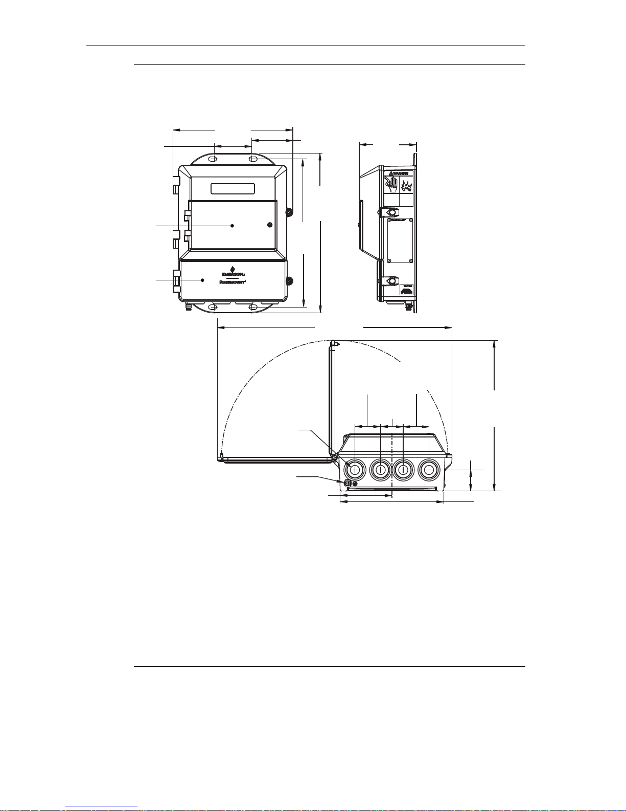
Rosemount 8712EM Dimensional DrawingFigure 3-1:
A
B
9.0
[229]
3.12
[79]
3.51
[89]
12.03
[306]
11.15
[283]
17.68
[449]
11.36
[289]
1.59
[40]
1.94
[49]
1.94
[49]
1.70
[43]
7.80
[198]
3.90
[99]
2.81
[71]
D
C
A. Conduit entry, 1/2-14 NPT (4 places)
B. Ground lug
C. LOI keypad cover
D. Lower cover opens for electrical connections
Note
Dimensions are in inches [Millimeters]
Electrical considerations
Before making any electrical connections to the transmitter, consider
national, local, and plant electrical installation requirements. Be sure to have
November 2017
Quick Start Guide
Quick Start Guide 7

the proper power supply, conduit, and other accessories necessary to comply
with these standards.
The transmitter requires external power. Ensure access to a suitable power
source.
Electrical DataTable 3-2:
Rosemount 8712EM Flow Transmitter
Power input AC power:
90–250VAC, 0.45A, 40VA
Standard DC power:
12–42VDC, 1.2A, 15W
Low power DC:
12–30VDC, 0.25A, 3W
Pulsed circuit Internally powered (Active): Outputs up to
12VDC, 12.1mA, 73mW
Externally powered (Passive): Input up to
28VDC, 100mA, 1W
4-20mA output circuit Internally Powered (Active): Outputs up to
25mA, 24VDC, 600mW
Externally Powered (Passive): Input up to
25mA, 30VDC, 750mW
Um 250V
Coil excitation output 500mA, 40V max, 9W max
Environmental considerations
To ensure maximum transmitter life, avoid extreme temperatures and
excessive vibration. Typical problem areas include the following:
• Tropical or desert installations in direct sunlight
• Outdoor installations in arctic climates
Remote mounted transmitters may be installed in the control room to
protect the electronics from the harsh environment and to provide easy
access for configuration or service.
Quick Start Guide
November 2017
8 Rosemount 8712EM Transmitter with HART Protocol

4 Mounting
Wall mount transmitters are shipped with mounting hardware for use on a 2in. pipe or flat surface.
Mounting bracketFigure 4-1:
A
B
C
A. U-bolt
B. Saddle clamp
C. Fasteners
4.1
Pipe mounting
1. Attach the saddle clamp to the pipe using the U-bolt mounting hardware.
2. Attach the transmitter to the saddle clamp assembly with appropriate
fasteners.
November 2017
Quick Start Guide
Quick Start Guide 9

4.2 Surface mounting
Attach the transmitter to the mounting location using customer supplied
mounting screws. The installation of the transmitter shall be rated for four (4)
times the weight of the transmitter or 44lbs ( 20kgs).
Quick Start Guide November 2017
10 Rosemount 8712EM Transmitter with HART Protocol
 Loading...