

Emerson Rosemount 8600 Series Quick Start Manual
Quick Start Guide
00825-0100-4860, Rev. EA
September 2016
Rosemount™ 8600 Series Vortex
Flowmeter
September 2016
2
Quick Start Guide
1.0 About this guide
This guide provides basic guidelines for the Rosemount™ 8600D Series Vortex
Flowmeter. It does not provide instructions for detailed configuration,
diagnostics, maintenance, service, troubleshooting, Explosion-proof,
Flameproof, or Intrinsically Safe (I.S.) installations. Refer to the Rosemount
8600D Reference Manual for more instruction. The manuals and this quick start
guide are also available electronically on EmersonProcess.com/Rosemount.
Explosions could result in death or serious injury.
Installation of this transmitter in an explosive environment must be in accordance with the appropriate
local, national, and international standards, codes, and practices. Review the approvals section of the
Rosemount 8600D Reference Manual for any restrictions associated with a safe installation.
Before connecting a HART
®
-based communicator in an explosive atmosphere, make sure the instruments
in the loop are installed in accordance with intrinsically safe or non-incendive field wiring practices.
Verify the operating atmosphere of the flowmeter is consistent with the appropriate product
certifications.
In an Explosion-proof/Flameproof installation, do not remove the flowmeter covers when power is applied
to the unit.
Electrical shock can result in death or serious injury.
Avoid contact with the leads and terminals. High voltage that may be present on leads can cause electrical
shock.
Contents
Mount the flowmeter . . . . . . . . . . . . . . . . page 3
Consider housing rotation . . . . . . . . . . . . page 9
Set jumpers and switches . . . . . . . . . . . page 10
Connect wiring and power up . . . . . . . .page 11
Verify configuration . . . . . . . . . . . . . . . . .page 13
Product certifications . . . . . . . . . . . . . . .page 16

Quick Start Guide
3
September 2016
2.0 Mount the flowmeter
Design process piping so the meter body will remain full, with no entrapped air.
The vortex flowmeter can be installed in any orientation without affecting
accuracy. However, the following are guidelines for certain installations.
2.1 Vertical mounting
If the vortex flowmeter will be installed in a vertical orientation:
Install upward or downward flow for gas or steam.
Install upward flow for liquids.
Figure 1. Vertical Installation
A. Gas flow
B. Liquid or gas flow
2.2 Horizontal mounting
Figure 2. Horizontal Installation
A. Preferred installation—meter body installed with electronics to side of pipe
B. Acceptable installation—meter body installed with electronics above pipe
For steam and fluids with small solids content, it is recommended to have the
flowmeter installed with the electronics to the side of the pipe. This will minimize
potential measurement errors by allowing the condensate or solids to flow under
the shedder bar without interrupting the vortex shedding.
BA
BA
September 2016
4
Quick Start Guide
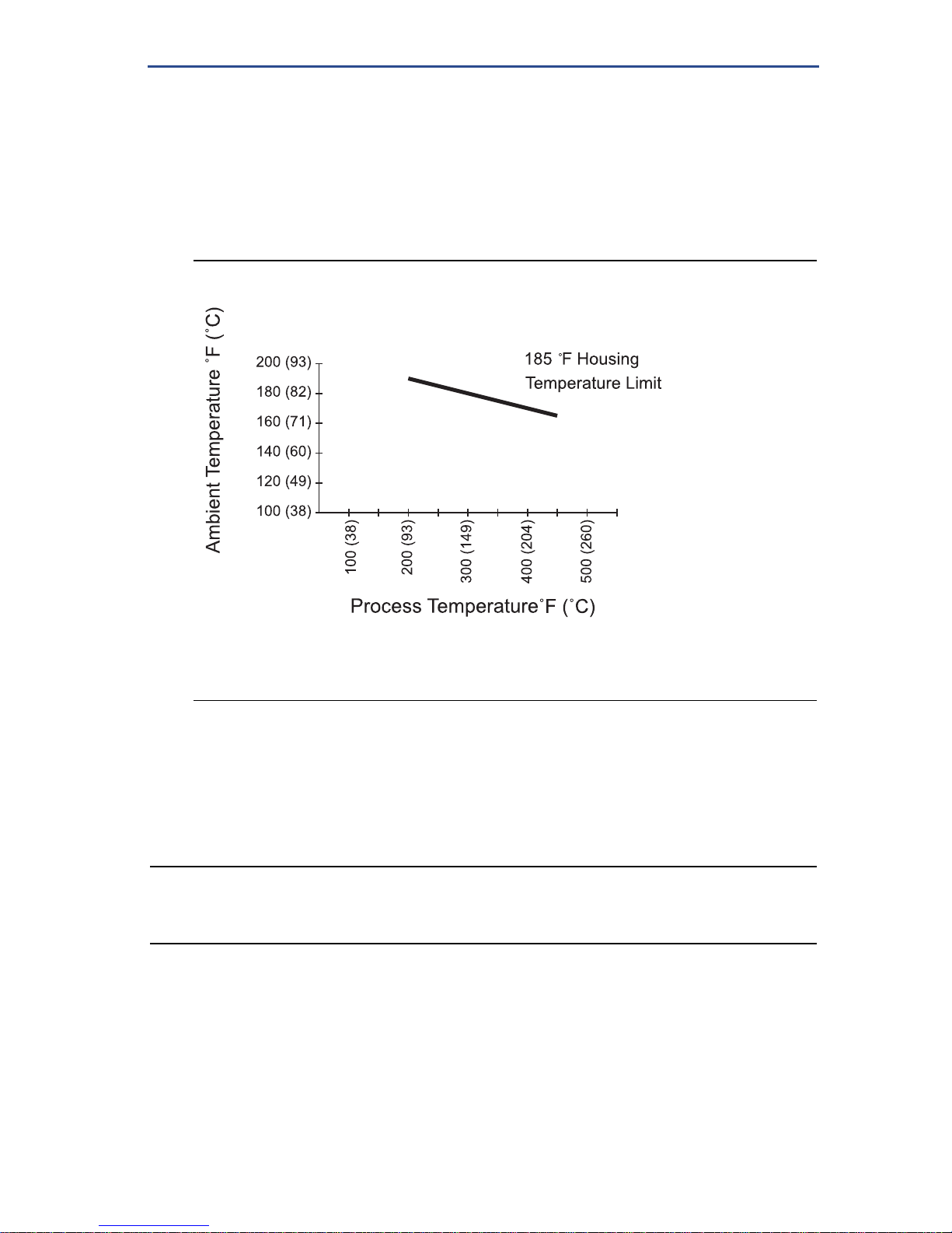
2.3 High temperature mounting
The maximum temperature for integral electronics is dependent on the ambient
temperature where the flowmeter is installed. The electronics must not exceed
185 °F (85 °C).
Figure 3 shows combinations of ambient and process temperatures needed to
maintain a housing temperature of less than 185 °F (85 °C).
Figure 3. Rosemount 8600D Ambient/Process Temperature Limits
The following orientations are recommended for applications with high process
temperatures.
Install with electronics head beside or below process pipe.
Insulation around pipe may be necessary to maintain ambient temperature
below 185 °F (85 °C).
Note
Insulate pipe and meter body only. Do not insulate support tube bracket or transmitter so heat
can be dissipated.
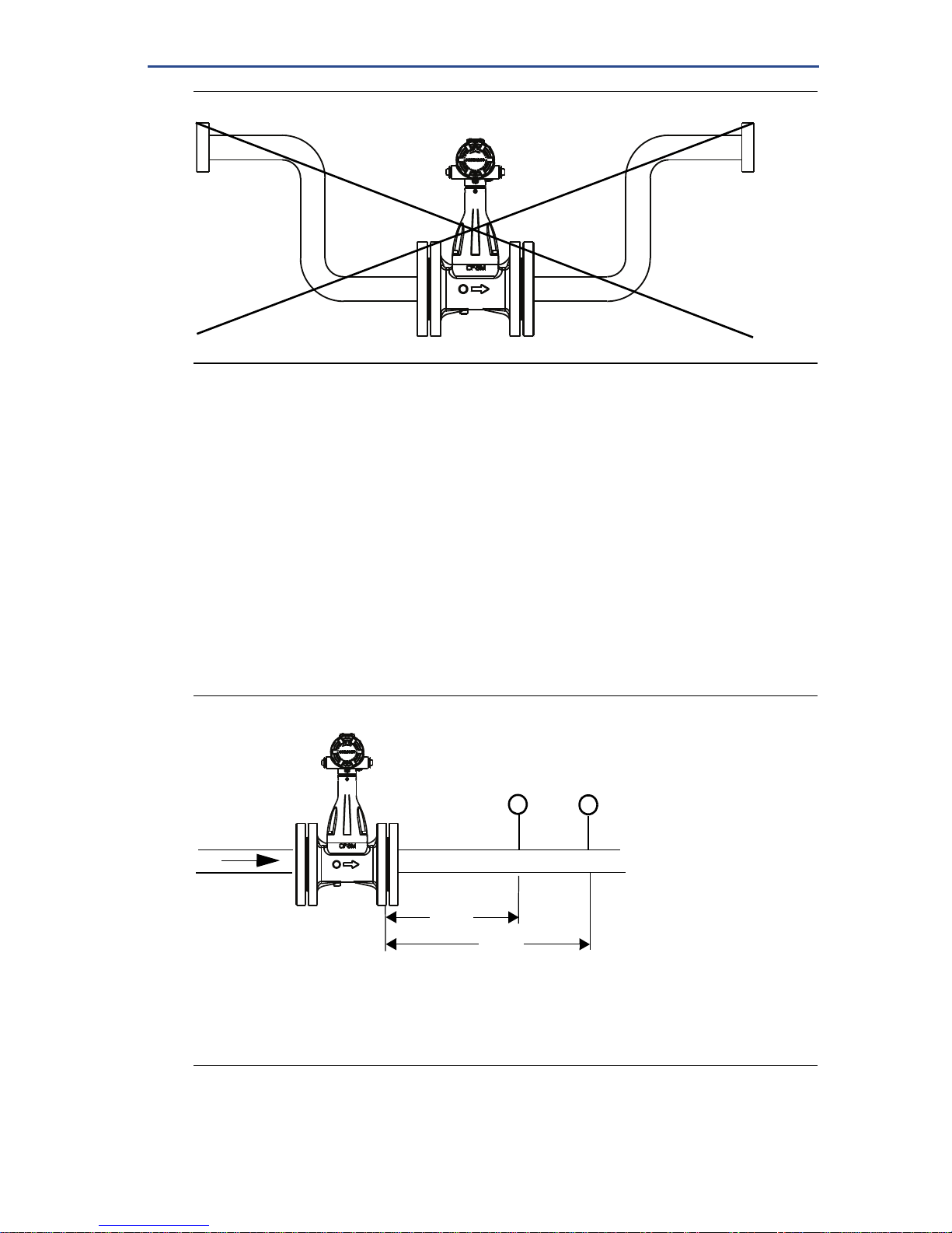
2.4 Steam installations
Avoid installation shown in Figure 4. Such conditions may cause a water-hammer
condition at start-up due to trapped condensation.
J^[_dZ_YWj[Zb_c_jiWh[\eh^eh_pedjWbf_f[WdZl[hj_YWbc[j[hfei_j_ed"m_j^c[j[hWdZ
f_f[_dikbWj[Zm_j^)_d$e\Y[hWc_Y\_X[h_dikbWj_ed$
Quick Start Guide
5
September 2016
Figure 4. Improper Installation
2.5 Upstream/downstream requirements
The Rosemount 8600D Flowmeter may be installed with a minimum of ten
straight pipe diameters (D) upstream and five straight pipe diameters (D)
downstream by following the K-factor corrections as described in the 8800
Installation Effects Technical Data Sheet (00816-0100-3250). No K-factor
correction is required if 35 straight pipe diameters upstream (35D) and 10
straight pipe diameters downstream (10D) are present.
2.6 External pressure/temperature transmitters
When using pressure and temperature transmitters in conjunction with the
Rosemount 8600D for compensated mass flows, install the transmitters
downstream of the Rosemount 8600D flowmeter as shown in Figure 5.
Figure 5. Upstream/Downstream Piping
A. Pressure transmitter
B. Four straight pipe diameters downstream
C. Temperature transmitter
D. Six straight pipe diameters downstream
A
C
D
B

September 2016
6
Quick Start Guide
2.7 Flanged-style installation
Figure 6. Flanged-Style Flowmeter Installation
A. Installation bolts and nuts (supplied by customer)
B. Gaskets (supplied by customer)
C. Flow
Note
The required bolt load for sealing the gasket joint is affected by several factors, including
operating pressure, gasket material, width, and condition. A number of factors also affect the
actual bolt load resulting from a measured torque, including condition of bolt threads, friction
between the nut head and the flange, and parallelism of the flanges. Due to these
application-dependent factors, the required torque for each application may be different. Follow
the guidelines outlined in ASME PCC-1 for proper bolt tightening. Make sure the flowmeter is
centered between flanges of the same nominal size as the flowmeter.
2.8 Remote electronics
If you order one of the remote electronics options (options R10, R20, R30, or
RXX), the flowmeter assembly ships in two parts:
1. The meter body with an adapter installed in the support tube and an
interconnecting coaxial cable attached to it.
2. The electronics housing installed on a mounting bracket.
Mounting
Mount the meter body in the process flow line as described earlier in this section.
Mount the bracket and electronics housing in the desired location. The housing
can be repositioned on the bracket to facilitate field wiring and conduit routing.
Cable connections
Refer to Figure 7 and the instructions on page 7 to connect the loose end of the
coaxial cable to the electronics housing.
C
B
A

Quick Start Guide
7
September 2016
Figure 7. Remote Electronics Installation
A.
1. If you plan to run the coaxial cable in conduit, carefully cut the conduit to the
desired length to provide for proper assembly at the housing. A junction box
may be placed in the conduit run to provide a space for extra coaxial cable
length.
2. Slide the conduit adapter or cable gland over the loose end of the coaxial
cable and fasten it to the adapter on the meter body support tube.
3. If using conduit, route the coaxial cable through the conduit.
4. Place a conduit adapter or cable gland over the end of the coaxial cable.
5. Remove the housing adapter from the electronics housing.
6. Slide the housing adapter over the coaxial cable.
A. Meter body J. Electronics housing
B. Support tube K. Ground connection
C. Sensor cable nut L. Housing base screw
D. Nut M. Housing adapter
E. Washer N. Housing adapter screws
F. Union
G. Meter adapter
O.
1
/2 in. NPT conduit adapter or cable gland
(supplied by customer)
H. Coaxial cable P. Coaxial cable nut
I.
1
/2 in. NPT Conduit adapter or cable
gland (supplied by customer)
The coaxial remote cable cannot be field terminated or cut to length. Coil any extra coaxial cable with no
less than a 2-in. (51 mm) radius.
A
Note: Consult factory for SST installation.
B
C
D
F
G
H
I
E
J
K
L
M
N
O
P
September 2016
8
Quick Start Guide
7. Remove one of the four housing base screws.
8. Attach and securely tighten the coaxial cable nut to the connection on the
electronics housing.
9. Attach the coaxial cable ground wire to the housing via the housing base
ground screw.
10. Align the housing adapter with the housing and attach with two screws.
11. Tighten the conduit adapter or cable gland to the housing adapter.
To prevent moisture from entering the coaxial cable connections, install the interconnecting coaxial cable in
a single dedicated conduit run or use sealed cable glands at both ends of the cable.
Quick Start Guide
9
September 2016
3.0 Consider housing rotation
The entire electronics housing may be rotated in 90° increments for easy viewing.
Use the following steps to change the housing orientation:
1. Loosen the four housing rotation set screws at the base of the electronics
housing with a 5/32” hex wrench by turning the screws clockwise (inward) until
they clear the support tube.
2. Slowly pull the electronics housing out of the support tube.
3. Unscrew the sensor cable from the housing with a
5
/16” open end wrench.
4. Rotate the housing to the desired orientation.
5. Hold it in this orientation while you screw the sensor cable onto the base of
the housing.
6. Place the electronics housing into the top of the support tube.
7. Use a hex wrench to turn the three housing rotation screws counter-clockwise
(outward) to engage the support tube.
Do not pull the housing more than 1.5 in. (40 mm) from the top of the support tube until the sensor cable is
disconnected. Damage to the sensor may occur if this sensor cable is stressed.
Do not rotate the housing while the sensor cable is attached to the base of the housing. This will stress the
cable and may damage the sensor.
 Loading...