

Page 1
Quick Start Guide
00825-0100-4378, Rev AD
June 2016
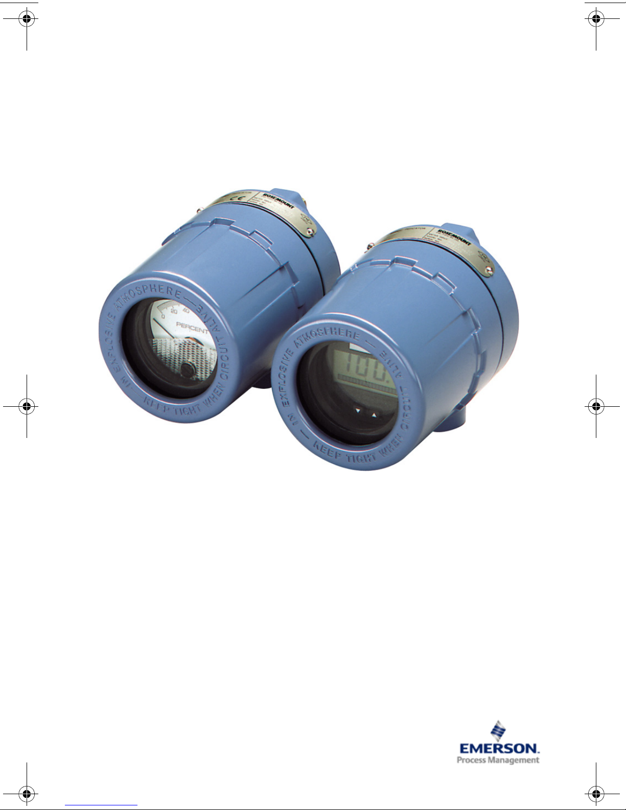
Rosemount™ 751 Field Signal Indicator
Page 2
Quick Start Guide
June 2016
This guide provides basic guidelines for Rosemount 751 Remote Indicator. It does not provide
instructions for configuration, diagnostics, maintenance, service, troubleshooting,
Explosionproof, Flameproof, or intrinsically safe (I.S.) installations. Refer to the Rosemount 751
Reference Manual (document number 00809-0100-4378) for more instruction. This manual is
also available electronically on www.rosemount.com.
Explosions could result in death or serious injury.
Installation of this indicator in an explosive environment must be in accordance with the
appropriate local, national, and international standards, codes, and practices. Review the
approvals section of the Rosemount 751 Reference Manual for any restrictions associated with
a safe installation.
In an Explosionproof/Flameproof installation, do not remove the indicator cover when power
is applied to the unit.
Electrical shock can result in death or serious injury.
Avoid contact with the leads and terminals. High voltage that may be present on leads can
cause electrical shock.
Contents
Installation . . . . . . . . . . . . . . . . . . . . . . . . . . . . 3
Configuration . . . . . . . . . . . . . . . . . . . . . . . . . 9
2
Product Certifications . . . . . . . . . . . . . . 11
Page 3
June 2016
A
B
C
D
E
F
G
H
I
J
K
L
M
N
Quick Start Guide
Installation
Assembly
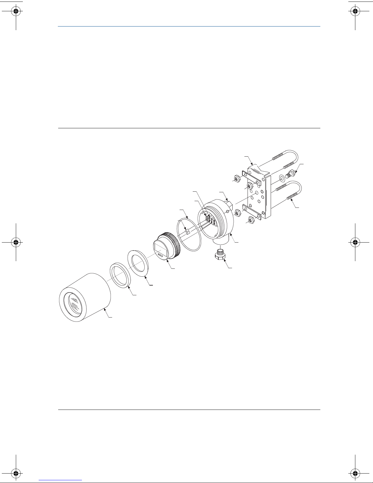
The Rosemount 751 Field Signal Indicator is comprised of the components shown
in Figure 1. The housing may contain an analog or LCD display meter. Both meters
are independent of component parts and are completely interchangeable. Both
meters plug into the terminal screws on the housing, as shown in Figure 1.
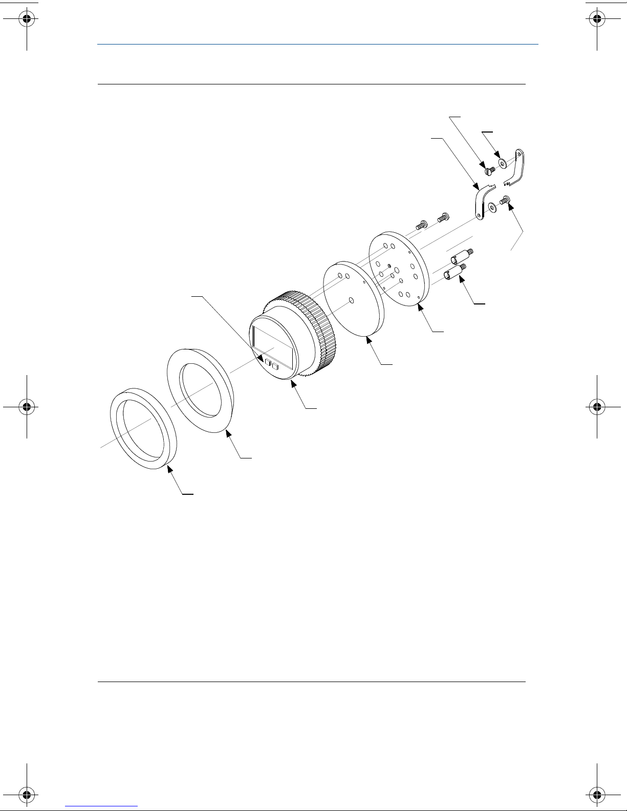
The meter subassembly contains the components shown in Figure 2.
Figure 1. Rosemount 751 Exploded View
A. Terminal screws
B. Housing O-ring
C. Field wiring terminals
D. Loop protection diode
E. Tapped mounting boss
F. Optional mounting bracket
G. Mounting bolt with washer
H. U-bolt for 2-in. pipe
I. Housing
J. Optional ¾ to ½-in. conduit reducing bushing
(if required)
K. Meter
L. Bushing
M. Foam spacer
N. Housing cover
3
Page 4
Quick Start Guide
A
B
C
D
K
J
I
H
G
F
E
Figure 2. Meter Exploded View
June 2016
A. Retaining straps
B. Mounting screw into housing
C. Washer for retaining strap
D. Mounting screws into mounting plate
E. Terminal screws (2)
F. Mounting plate
G. Spacer plate
H. LCD display
I. Bushing
J. Foam spacer
K. Configuration buttons
4
Page 5

June 2016
Quick Start Guide
Wiring diagrams
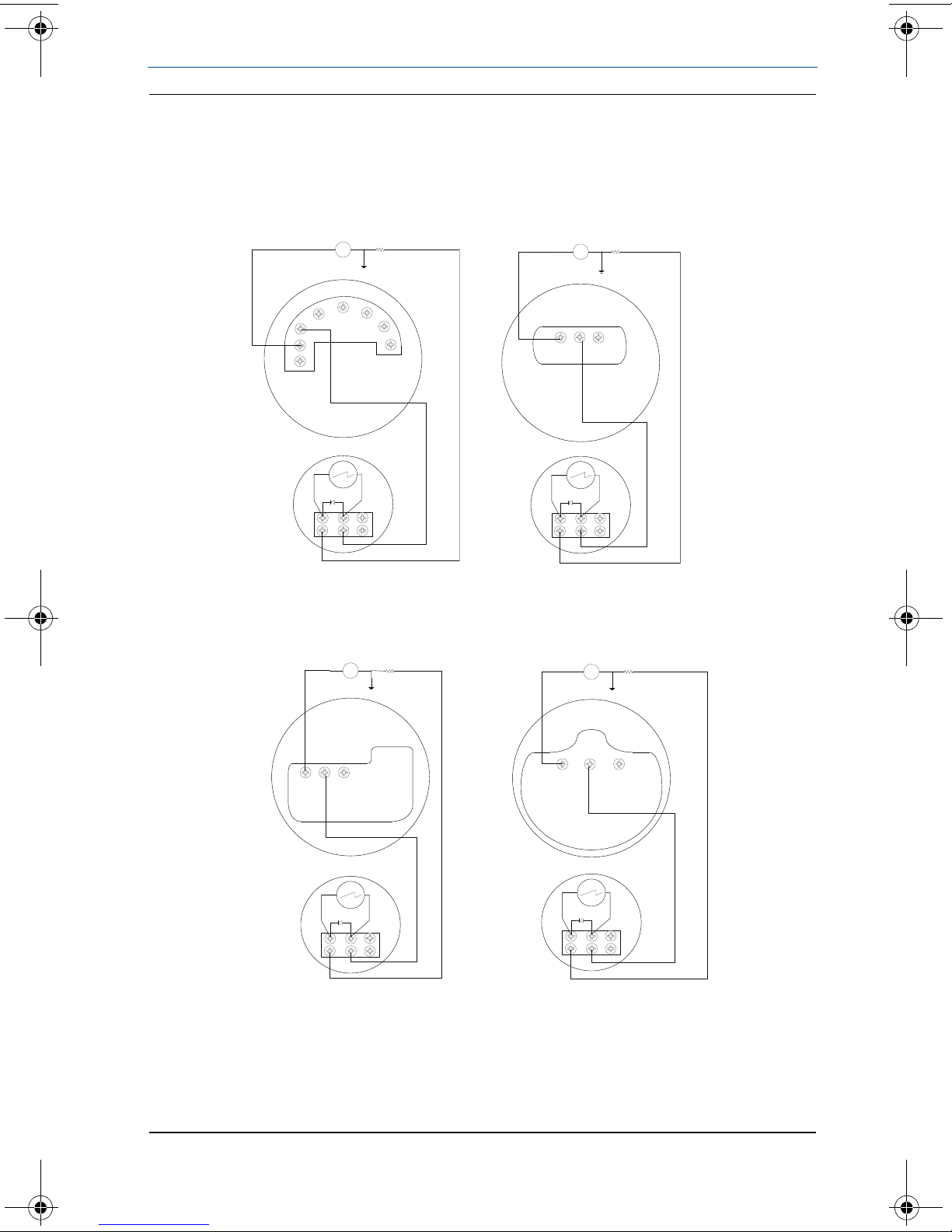
Use the following wiring diagrams to wire the Rosemount 751 Field Signal
Indicator, in series or in parallel, with Rosemount transmitters. Use shielded cable
for best results in electrically noisy environments.
It is recommended that the Rosemount 751 indicator be wired in a series
configuration when the 4-20 mA transmitter does not contain a test terminal. The
Rosemount 751 is designed so the analog or LCD display meter can be removed
from the housing without impacting the integrity of the 4-20 mA loop. Removal
of the entire Rosemount 751 device from the series configuration will disrupt the
loop.
5
Page 6
Quick Start Guide
A
A
751
4–20 dc Input Signal for
Rosemount 2051
4–20 mA dc Input Signal for
Rosemount 3144P
+
+
–
–
C
B
T
2051
+
–
+
–
3144P
C
B
–
+
T
751
+
–
A
A
4–20 dc Input Signal for
Rosemount 3051S
4–20 mA dc Input Signal for
Rosemount 3051C
+
+
–
–
C
B
T
3051C
751
+
–
+
+
–
–
C
B
T
3051S
751
+
–
Figure 3. Rosemount 751 Series Wiring Diagrams
Rosemount 3144P Temperature Transmitters and Rosemount 2051,
3051C, or 3051S Pressure Transmitters
June 2016
A. Power supply
B. Load resistor
C. Optional ground
6
Page 7

June 2016
Quick Start Guide
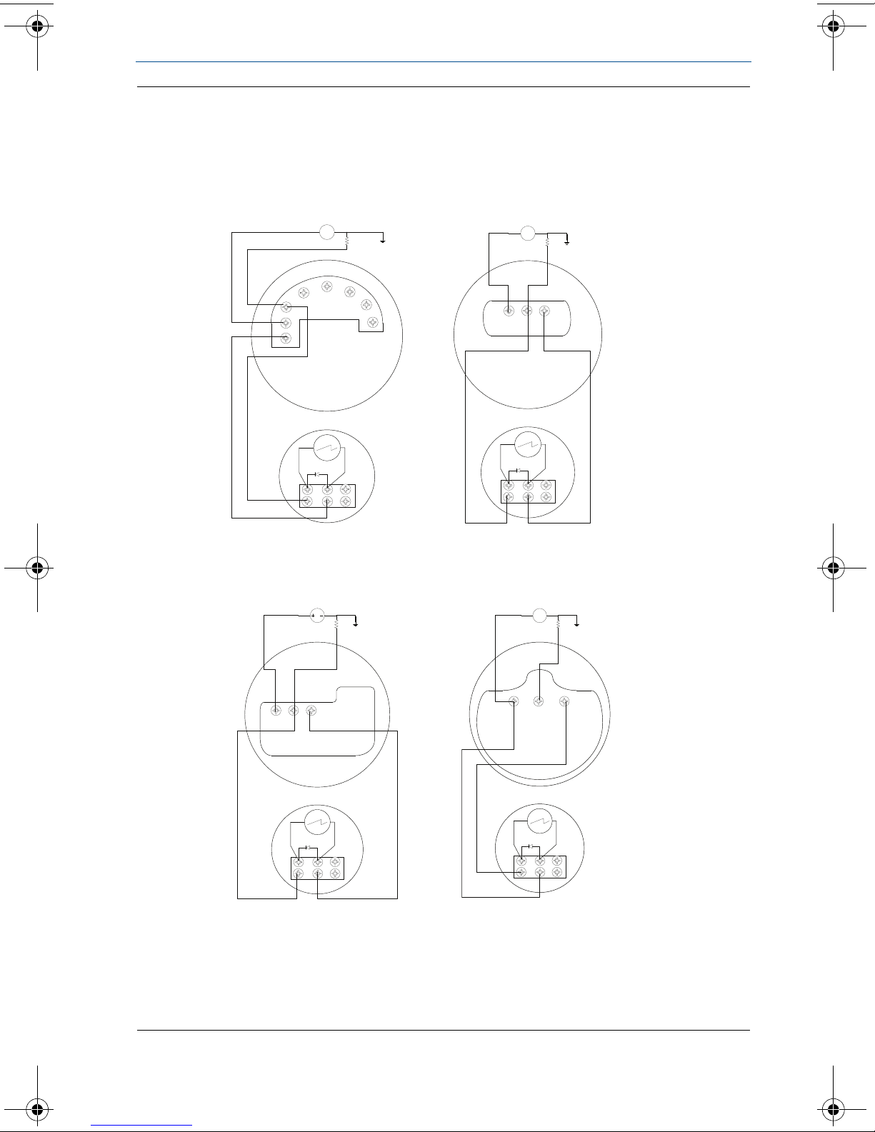
It is recommended that the Rosemount 751 indicator be wired in a parallel
configuration when the 4-20 mA transmitter includes a test terminal. Utilization
of the test terminal is required in a parallel configuration. Connecting the 751
indicator across the positive and negative terminals of the 4-20 mA transmitter
could impact the loop.
A parallel configuration will allow the removal of the 751 indicator without
affecting the integrity of the 4-20 mA loop. Additionally, spare 751 indicators can
be added without disrupting the loop.
7
Page 8
Quick Start Guide
A
A
751
4–20 dc Input Signal for
Rosemount 2051
4–20 mA dc Input Signal for
Rosemount 3144P
+
+
–
–
C
B
T
2051
+
–
+
–
3144P
C
B
–
+
T
751
+
–
A
A
4–20 dc Input Signal for
Rosemount 3051S
4–20 mA dc Input Signal for
Rosemount 3051C
+
+
–
–
C
B
T
3051C
751
+
–
+
+
–
–
C
B
T
3051S
751
+
–
3051C
4–20 mA dc Input Signal for
Rosemount 3051C
June 2016
Figure 4. Rosemount 751 Parallel Wiring Diagrams
Parallel Wiring Diagrams for Rosemount 3144P Temperature Transmitter
and Rosemount 2051, 3051C or 3051S Pressure Transmitters
A. Power supply
B. Load resistor
C. Optional ground
8
Page 9
June 2016
Quick Start Guide
Configuration
LCD display configuration
The 20-segment bar graph is factory calibrated and represents 4–20 mA directly,
but the end points of the LCD display are user-definable. The meter requires a
current between 4 and 20 mA in order to be scaled, but the actual value of the
current is not significant.
Remove the cover
Explosions can result in death or serious injury. Do not remove the instrument cover in
explosive environments when the circuit is alive.
1. Unscrew and remove the transparent housing cover from the LCD display
body.
Position the decimal point and select the meter function
1. Press the left and right configuration buttons simultaneously and release them
immediately.
2. To move the decimal point to the desired location, press the left configuration
button.
Note
The decimal point wraps around.
3. To scroll through the mode options, press the right configuration button
repeatedly until the meter displays the desired mode (See Tabl e 1).
Note
The LCD display time-out is approximately 16 seconds. If you do not press the configuration
buttons within 16 seconds, the indicator will revert to reading the current signal.
9
Page 10
Quick Start Guide
Table 1. LCD Display Mode Options
Options Relationship between input signal and digital display
L in Linear
LinF Linear with five-second filter
Srt Square root
SrtF Square root with five-second filter
Square root function only relates to the digital display. The bar graph output remains
linear with the current signal.
Square root response
The digital display will be proportional to the square root of the input current where 4 mA = 0 and 20 mA =
1.0, scaled per the calibration procedure. The transition point from linear to square root is at 25 percent of
full scale flow.
Filter response operates upon “present input” and “input received in the previous five
second interval” in the following manner:
Display = (0.75 previous input) + (0.25 present input)
This relationship is maintained provided that the previous reading minus the present
reading is less than 25 percent of full scale.
June 2016
Store the information
1. Press both configuration buttons simultaneously for two seconds.
Note
The meter displays “- -” for approximately 7.5 seconds while the information is being stored.
Set the display equivalent to a 4 mA signal
1. Press the left configuration button for two seconds.
2. To decrease the display numbers, press the left configuration button. To
increase the numbers, press the right configuration button. Set the numbers
between –999 and 1000.
3. To store the information, simultaneously press both configuration buttons for
two seconds.
Set the display equivalent to a 20 mA signal
1. Press the right configuration button for two seconds.
2. To decrease the display numbers, press the left configuration button. To
increase the numbers, press the right configuration button. Set the numbers
between –999 and 9999.
Note
The sum of the 4 mA point and the span must not exceed 9999.
3. To store the information, simultaneously press both configuration buttons for
two seconds. The LCD display meter is now configured.
Replace the cover
1. Make sure the rubber gasket is seated properly, and thread the transparent
housing cover onto the LCD display meter body.
10
Page 11

June 2016
Quick Start Guide
Product Certifications
European Directive Information
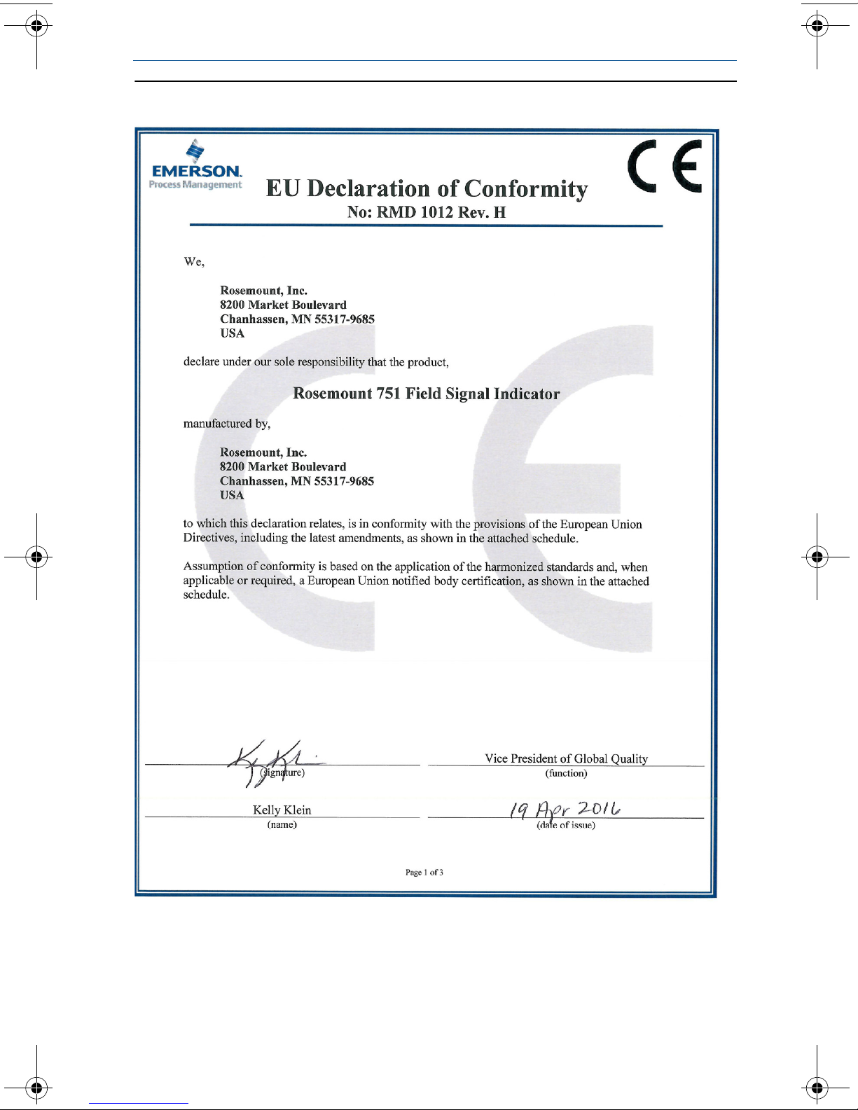
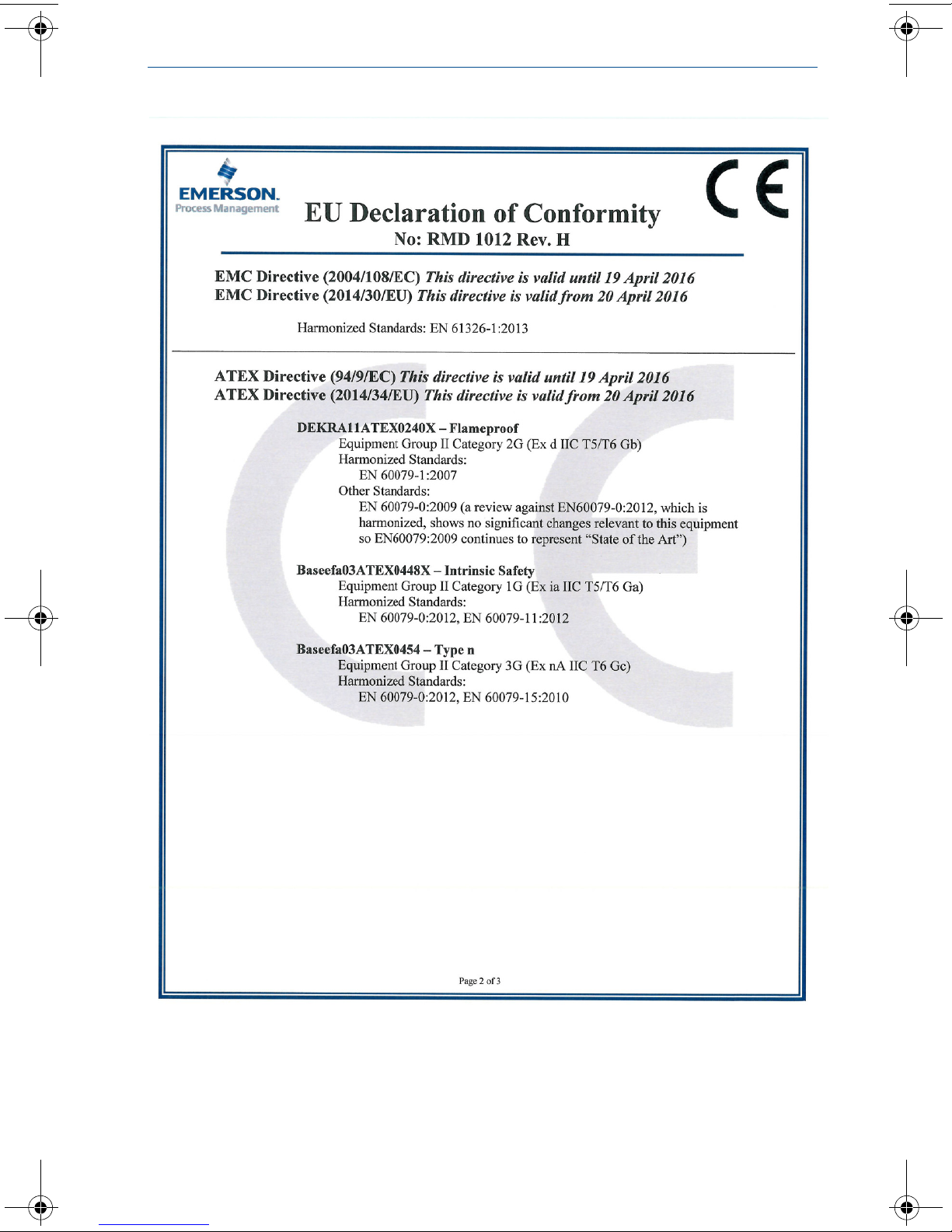
A copy of the EC Declaration of Conformity can be found at the end of the Quick
Start Guide. The most recent revision of the EC Declaration of Conformity can be
found at www.EmersonProcess.com.
Ordinary Location Certification
As standard, the transmitter has been examined and tested to determine that the
design meets the basic electrical, mechanical, and fire protection requirements
by a nationally recognized test laboratory (NRTL) as accredited by the Federal
Occupational Safety and Health Administration (OSHA).
Installing Equipment in North America
The US National Electrical Code® (NEC) and the Canadian Electrical Code (CEC)
permit the use of Division marked equipment in Zones and Zone marked
equipment in Divisions. The markings must be suitable for the area classification,
gas, and temperature class. This information is clearly defined in the respective
codes.
USA
E5 USA Explosion-proof
Certificate: 0T2H8.AE
Standards: FM Class 3600: 1989, FM Class 3615: 1989
Markings: XP CL I, DIV 1, GP B, C, D; DIP CL II/III, DIV 1, GP E, F, G; -40 °C ≤ Ta ≤ +85 °C;
Type 4X
I5 USA Intrinsically Safe; Nonincendive
Certificate: 0T9H2AX
Standards: FM Class 3600: 2011, FM Class 3610: 2010, FM Class 3611: 2004, FM Class
3810: 1989, NEMA-250: 1991, ANSI/ISA 60079-0: 2009, ANSI/ISA 60079-11:
2009
Markings: IS CL I / II / III, DIV 1, GP A, B, C, D, E, F, G; T5; IS CL I, Zone 0, AEx ia IIC T5; NI CL
I, DIV 2, GP A, B, C, D T5; (-60 °C ≤ T
00751-0074; Type 4X
Special Condition for Safe Use (X):
1. The apparatus enclosure contains aluminum and is considered to constitute a
potential risk of ignition by impact or friction. Care must be taken into account during
installation and use to prevent impact or friction.
≤ +60 °C); when installed per
a
11
Page 12
Quick Start Guide
Canada
E6 Canada Explosionproof
Certificate: 1718395
Standards: CSA Std C22.2 No. 25-1966; CSA Std C22.2 No. 30-M1986; CAN/CSA-C22.2
Markings: Explosionproof for CL I, DIV 1, GP C, D; CL II, DIV 1, GP E, F, G; CL III; DIV 1; CL I
I6 Canada Intrinsically Safe
Certificate: 1718395
Standards: CSA Std C22.2 No. 25-1966; CSA Std C22.2 No. 30-M1986; CAN/CSA-C22.2
Markings: Intrinsically Safe for CL I DIV 1; when installed per 00751-0068; Type 4X
Europe
E8 ATEX Flameproof
Certificate: DEKRA11ATEX0240X
Standards: EN 60079-0:2009, EN 60079-1:2007
Markings: II 2 G Ex d IIC T5/T6 Gb, T6(-20 °C ≤ T
Special Condition for Safe Use (X):
1. The original manufacturer shall be contacted for information on the dimensions of
the flameproof joints.
June 2016
No. 94-M91; CSA Std C22.2 No. 142-M1987
DIV 2, GP A, B, C, D; Type 4X
No. 94-M91; CSA Std C22.2 No. 142-M1987; CAN/CSA-C22.2 No. 157-92;
CSA Std C22.2 No. 213-M1987
≤ +40 °C), T5(-20 °C ≤ Ta ≤ +70 °C)
a
I8 ATEX Intr insic Safety
Certificate: Baseefa03ATEX0448X
Standards: EN 60079-0:2012, EN 60079-11:2012
Markings: II 1 G Ex ia IIC T5/T6 Ga; T6(-60 °C ≤ T
Special Condition for Safe Use (X):
1. The enclosure may be made from aluminum alloy and given a protective
polyurethane or epoxy polyester paint finish; however, care should be taken to
protect it from impact or abrasion if located in a zone 0 environment.
N1 ATE X Type n
Certificate: Baseefa03ATEX0454
Standards: EN 60079-0:2012; EN 60079-15:2010
Markings: II 3 G Ex nA IIC T6 Gc; (-40 °C ≤ T
International
E7 IECEx Flameproof
Certificate: IECEx DEK 11.0082X
Standards: IEC 60079-0:2007-10; IEC 60079-1:2007-04
Markings: Ex d IIC T5/T6 Gb, T6(-20 °C ≤ T
Special Condition for Safe Use (X):
1. The original manufacturer shall be contacted for information on the dimensions of
the flameproof joints.
≤ +40 °C), T5(-60 °C ≤ Ta ≤ +80 °C)
a
≤ +70 °C)
a
≤ +40 °C), T5(-20 °C ≤ Ta ≤ +70 °C)
a
12
Page 13

June 2016
I7 IECEx Intrinsic Safety
Certificate: IECEx BAS 11.0064X
Standards: IEC 60079-0: 2011; IEC 60079-11: 2011
Markings: Ex ia IIC T5/T6 Ga; T6(-60 °C ≤ T
Special Condition for Safe Use (X):
1. The enclosure may be made of aluminum alloy and given a protective polyurethane or
epoxy polyester paint finish; however, care should be taken to protect it from impact
or abrasion if located in a Zone 0 environment.
Brazil
E2 INMETRO Flameproof
Certificate: NCC 12.1204X
Standards: ABNT NBR IEC 60079-0:2011, ABNT NBR IEC 60079-1:2011
Markings: Ex d IIC T5/T6 Gb; T6(-20 °C ≤ T
Special Condition for Safe Use (X):
1. The manufacturer should be contacted for information on the dimensions of the
flameproof joints.
I2 INMETRO Intrinsic Safety
Certificate: UL-BR 15.1094X
Standards: ABNT NBR IEC 60079-0:2008 + ERRATA 1:2011, ABNT NBR IEC
Markings: Ex ia IIC T5/T6 Ga; T6(-60 °C ≤ T
Special Condition for Safe Use (X):
1. The enclosure may be made of aluminum alloy and given a protective polyurethane or
epoxy polyester paint finish; however, care should be taken to protect it from impact
or abrasion if located in places where EPL Ga is required.
60079-11:2009
Quick Start Guide
≤ +40 °C), T5(-60 °C ≤ Ta ≤ +80 °C)
a
≤ +40 °C), T5(-20 °C ≤ Ta ≤ +70 °C)
a
≤ +40 °C), T5(-60 °C ≤ Ta ≤ +80 °C)
a
China
E3 China Flameproof
Certificate: GYJ12.1034X
Standards: GB 3836.1-2010, GB 3836.2-2010
Markings: Ex d IIC T6 Gb
Special Conditions for Safe Use (X):
1. Symbol “X” is used to denote specific conditions of use: Contact the original
manufacturer when repair work relates to the flamepath.
2. Ambient temperature range is: -20 °C ≤ T
3. The earth connection facility in the enclosure should be connected reliably.
4. During installation, there should be no mixture harmful to flameproof housing.
5. During installation in hazardous location. Cable glands, conduits and blanking plugs,
certified by state-appointed inspection bodies with Ex d IIC Gb degree, should be
used.
6. During installation, use and maintenance in explosive gas atmospheres, observe the
warning “Do not open when energized.”
7. End users is not permitted to change any components insides, but to settle the
problem in conjunction with manufacturer to avoid damage to the product.
8. When installation, use and maintenance of this product, observe following standards:
GB3836.13-1997 “Electrical apparatus for explosive gas atmospheres Part 13: Repair
and overhaul for apparatus used in explosive gas atmospheres.”
GB3836.15-2000 “Electrical apparatus for explosive gas atmospheres Part 15:
Electrical installations in hazardous area (other than mines).”
≤ +60 °C.
a
13
Page 14

Quick Start Guide
GB3836.16-2006 “Electrical apparatus for explosive gas atmospheres Part 16:
Inspection and maintenance of electrical installation (other than mines).”
GB50257-1996 “Code for construction and acceptance of electric device for
explosion atmospheres and fire hazard electrical equipment installation
engineering.”
EAC - Belarus, Kazakhstan, Russia
EM Technical Regulations Customs Union (EAC) Flameproof
Certificate: RU C-US.GB05.B.00285
Markings:1Ex d IIC T5…T6 X; T5 (-20 °C ≤ T
IM Technical Regulations Customs Union (EAC) Intrinsic Safety
Certificate: RU C-US.GB05.B.00285
Markings:0Ex ia IIC T5…T6 X; T5 (-60 °C ≤ T
NM Technical Regulations Customs Union (EAC) Type n
Certificate: RU C-US.GB05.B.00285
Markings:Ex nA IIC T6 (-40 °C ≤ T
≤ +70 °C);
a
a ≤ +70 °C); T6 (-20 °C ≤ Ta ≤ +40 °C);
a
≤ +80 °C); T6 (-60 °C ≤ Ta ≤ +40 °C);
a
Combinations
K2 Combination of E2 and I2
K5 Combination of E5 and I5
C6 Combination of E6 and I6
KM Combination of EM, IM, and NM
June 2016
14
Page 15
June 2016
Figure 5. Rosemount 751 Declaration of Conformity
Quick Start Guide
15
Page 16
Quick Start Guide
June 2016
16
Page 17
Page 18
Quick Start Guide
ᴹ
㇑᧗⢙䍘䎵䗷ᴰབྷ⎃ᓖ䲀٬Ⲵ䜘Ԧරࡇ㺘
䜘Ԧ〠
Part Name
ᴹᇣ⢙䍘䍘Hazardous Substances
䫵
Lead
(Pb)
⊎
Mercury
(Hg)
䭹
Cadmium
(Cd)
ޝԧ䬜䬜
Hexavalent
Chromium
(Cr +6)
ཊⓤ㚄㚄㤟
Polybrominated
biphenyls
(PBB)
ཊⓤ㚄㚄㤟䟊
Polybrominated
diphenyl ethers
(PBDE)
⭥ᆀ㓴Ԧ
Electronics
Assembly
X O O O O
O
༣փ㓴Ԧ
Housing
Assembly
O O O X O
O
Րᝏಘ㓴Ԧ
Sensor
Assembly
X O O O O
O
June 2016
China RoHS
Rosemount 751
List of Rosemount 751 Parts with China RoHS Concentration above MCVs
ᵜ㺘Ṭ㌫ᦞ
This table is proposed in accordance with the provision of SJ/T11364.
Ѫ䈕䜘ԦⲴᡰᴹ൷䍘ᶀᯉѝ䈕ᴹᇣ⢙䍘Ⲵ䟿൷վҾ
O:
O: Indicate that said hazardous substance in all of the homogeneous materials for this part is below the limit requirement of
GB/T 26572.
Ѫ൘䈕䜘Ԧᡰ֯⭘Ⲵᡰᴹ൷䍘ᶀᯉ䟼ˈ㠣ቁᴹа㊫൷䍘ᶀᯉѝ䈕ᴹᇣ⢙䍘Ⲵ䟿儈Ҿ
X:
X: Indicate that said hazardous substance contained in at least one of the homogeneous materials used for this part is above
the limit requirement of GB/T 26572.
SJ/T11364
Ⲵ㿴ᇊ㘼ࡦ
GB/T 26572
ᡰ㿴ᇊⲴ䲀䟿㾱≲
GB/T 26572
ᡰ㿴ᇊⲴ䲀䟿㾱≲
18
Page 19

June 2016
Quick Start Guide
19
Page 20
Rosemount World Headquarters
Emerson Process Management
6021 Innovation Blvd
Shakopee, MN 55379, USA
+1 800 999 9307 or +1 952 906 8888
+1 952 949 7001
[email protected]
North America Regional Office
Emerson Process Management
8200 Market Blvd.
Chanhassen, MN 55317, USA
+1 800 999 9307 or +1 952 906 8888
+1 952 949 7001
[email protected]
Latin America Regional Office
Emerson Process Management
1300 Concord Terrace, Suite 400
Sunrise, Florida, 33323, USA
+1 954 846 5030
+1 954 846 5121
[email protected]
00825-0100-4378
Quick Start Guide
00825-0100-4378, Rev. AD
June 2016
Europe Regional Office
Emerson Process Management Europe GmbH
Neuhofstrasse 19a P.O. Box 1046
CH 6340 Baar
Switzerland
+41 (0) 41 768 6111
+41 (0) 41 768 6300
[email protected]
Asia Pacific Regional Office
Emerson Process Management Asia Pacific Pte Ltd
1 Pandan Crescent
Singapore 128461
+65 6777 8211
+65 6777 0947
Middle East and Africa Regional Office
Emerson Process Management
Emerson FZE P.O. Box 17033,
Jebel Ali Free Zone - South 2
Dubai, United Arab Emirates
+971 4 8118100
+971 4 8865465
Standard Terms and Conditions of Sale can be found at:
www.Emerson.com/en-us/pages/Terms-of-Use.aspx
The Emerson logo is a trademark and service mark of Emerson Electric Co.
Rosemount and Rosemount logotype are trademarks of Emerson Process
Management.
National Electrical Code is a registered trademark of National Fire
Protection Association, Inc.
All other marks are the property of their respective owners.
© 2016 Emerson Process Management. All rights reserved.
 Loading...