

Page 1

Quick Installation Guide
Wireless Considerations
Step 1: Physical Installation
Step 2: Device Network Configuration
Step 3: Verify Operation
Product Certifications
EC Declaration of Conformity
Start
End
00825-0200-4708, Rev AD
April 2012
Rosemount 708
Rosemount 708 Wireless Acoustic Transmitter
www.rosemount.com
Page 2
Quick Installation Guide
IMPORTANT NOTICE
WARNING
IMPORTANT NOTICE
Emerson Process Management
Rosemount Division
8200 Market Boulevard
Chanhassen, MN USA 55317
T (US) (800) 999-9307
T (Intnl) (952) 906-8888
F (952) 906-8889
Rosemount Temperature GmbH
Frankenstrasse 21
63791 Karlstein
Germany
T 49 (6188) 992 0
F 49 (6188) 992 112
Emerson Process Management
Asia Pacific Private Limited
1 Pandan Crescent
Singapore 128461
T (65) 6777 821 1
F (65) 6777 0947 / (65) 6777 0743
Enquiries@AP.EmersonProcess.com
00825-0200-4708, Rev AD
Rosemount 708
© 2012 Rosemount Inc. All rights reserved All marks property of owner.
Standard Terms and Conditions of Sale can be found at www.rosemount.com/terms_of_sale
The Emerson logo is a trade mark and service mark of Emerson Electric Co.
Rosemount and the Rosemount logotype are registered trademarks of Rosemount Inc.
This installation guide provides basic guidelines for the Rosemount® 708. It does not
provide instructions for detailed configuration, diagnostics, maintenance, service,
troubleshooting, or installations. Refer to the Rosemount 708 Reference Manual
(Document Number 00809-0100-4708) for more instruction. This guide and the manual
are available electronically on www.rosemount.com.
April 2012
Explosions could result in death or serious injury:
Installation of this transmitter in an explosive environment must be in accordance with the appropriate
local, national, and international standards, codes, and practices. Please review the Product
Certifications section for any restrictions associated with a safe installation.
• Before connecting a Field Communicator in an explosive atmosphe re, ensure the in stru ment s are
installed in accordance with intrinsically safe field wiring practices.
This device complies with Part 15 of the FCC Rules. Operation is subject to the following conditions.
This device may not cause harmful interference. This device must accept any interference received,
including interference that may cause undesired operation.
This device must be installed to ensure a minimum antenna separation distance of 8 in. (20 cm) from
all persons.
The Power Module may be replaced in a hazardous area. The Power Module has surface resistivity
greater than one gigaohm and must be properly installed in the wireless device enclosure. Care must
be taken during transportation to and from the point of installation to prevent a potential electrostatic
charging hazard.
Polymer enclosure has surface resistivity greater than one gigaohm. Care must be taken during
transportation to and from the point of installation to prevent a potential electrostatic charging hazard.
Shipping considerations for wireless products:
The unit was shipped to you without the Power Module installed. Please remove the Power Module
prior to shipping the unit.
Each Power Module contains one “D” size primary lithium battery. Primary lithium batteries are
regulated in transportation by the U.S. Department of Transportation, and are also covered by IATA
(International Air Transport Association), ICAO (International Civil A viation Organization), and ARD
(European Ground Transportation of Dangerous Goods). It is the responsibility of the shipper to
ensure compliance with these or any other local requirements. Please consult current regula tions and
requirements before shipping.
2
Page 3
Quick Installation Guide
1
2
3
4
1
5
00825-0200-4708, Rev AD
April 2012
Rosemount 708
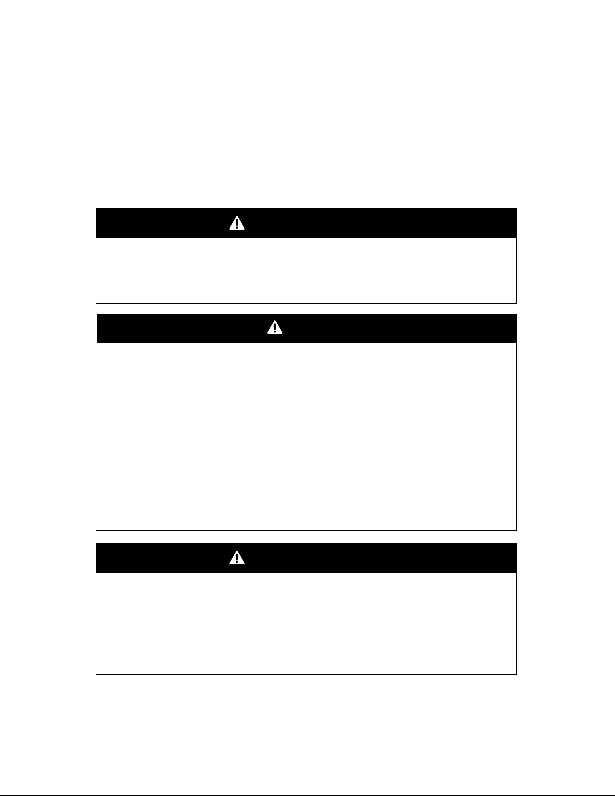
Rosemount 708 Wireless Acoustic Transmitter Overview
1. Power Module cover – Location of Power Module in device. Unscrew cap for access to
Power Module.
2. Waveguide – Location of the acoustic and temperature sensors.
3. Electronics cover – The cover is sealed and cannot be removed.
4. Stainless steel mounting bands – Used to connect the acoustic transmitter to the piping.
5. Pipe - The acoustic transmitter is installed directly to the pipe.
3
Page 4
Quick Installation Guide
00825-0200-4708, Rev AD
Rosemount 708
April 2012
WIRELESS CONSIDERATIONS
Power Up Sequence
The Smart Wireless Gateway should be installed and functioning properly before any
wireless devices are powered. Install the Power Module, Smart Wireless 701PGNKF into
the 708 to power the device. This results in a simpler and faster network installation.
Enabling Active Advertising on the Gateway ensures that new devices are able to join the
network faster. For more information see the Smart Wireless Gateway Manual (Document
No. 00809-0200-4420).
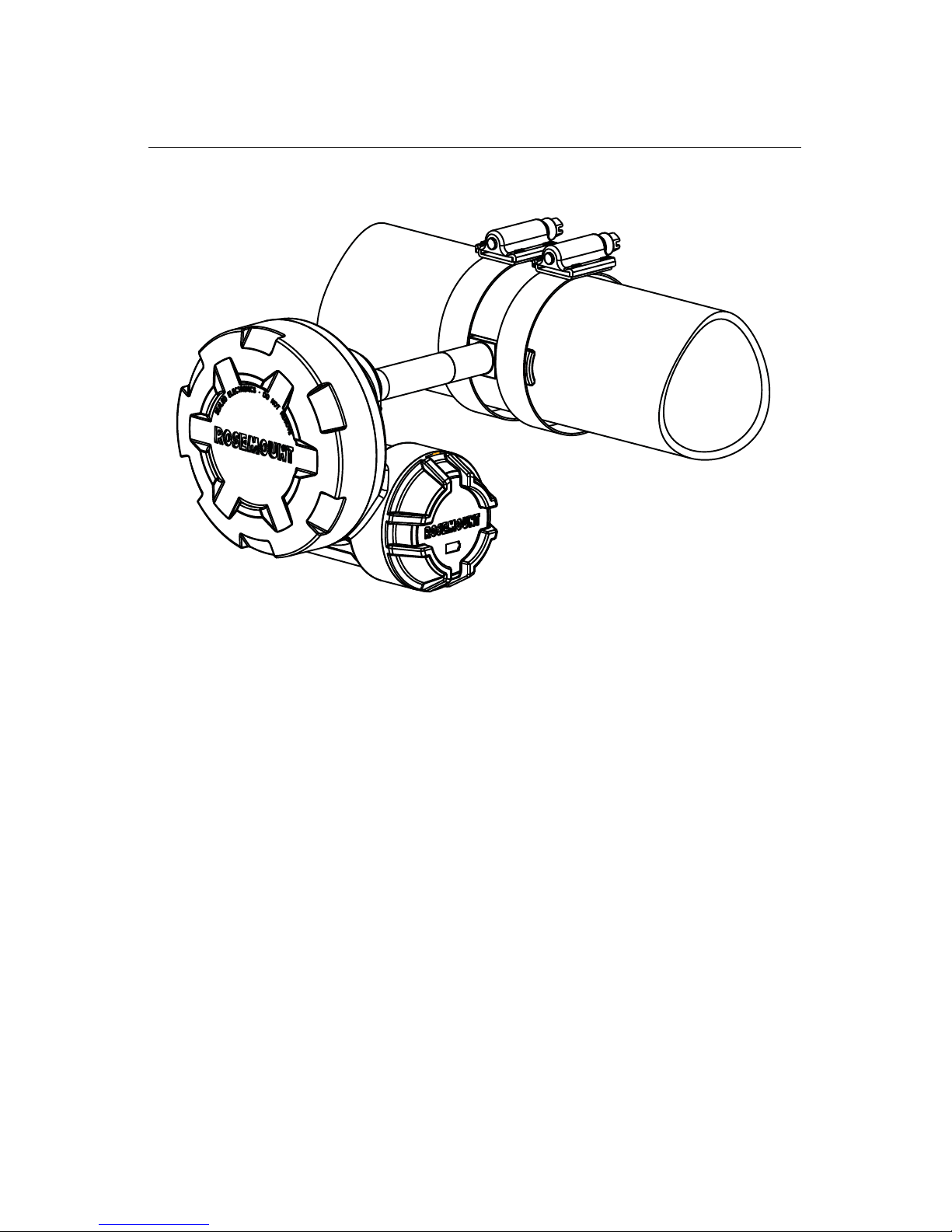
Antenna Position
The antenna is internal to the acoustic transmitter. To achieve optimal range, orient the
transmitter with the waveguide horizontal and the Power Module closest to the ground as
shown in Figure 1. Good connectivity can also be achieved in other orientations. The
antenna should also be approximately 3 ft. (1 m) from any large structure, building, or
conductive surface to allow for clear communication to other devices.
Figure 1. Antenna Position
Field Communicator Connections
The Power Module needs to be installed in the device for the Field Communicator to
interface with the 708. This transmitter uses the Green Power Module; please order model
number 701PGNKF. Field communication with this device requires a HART-based Field
Communicator using the correct 708 DD. Field Communicator connections are located on
the Power Module. The Power Module is keyed and can only be inserted in one orientation.
Refer to Figure 2 for instructions on connecting the Field Communicator to the 708.
Figure 2. Connection Diagram
4
Page 5
Quick Installation Guide
STEP 1: PHYSICAL INSTALLATION
00825-0200-4708, Rev AD
April 2012
The acoustic transmitter is connected directly to the piping that is being measured.
Rosemount 708
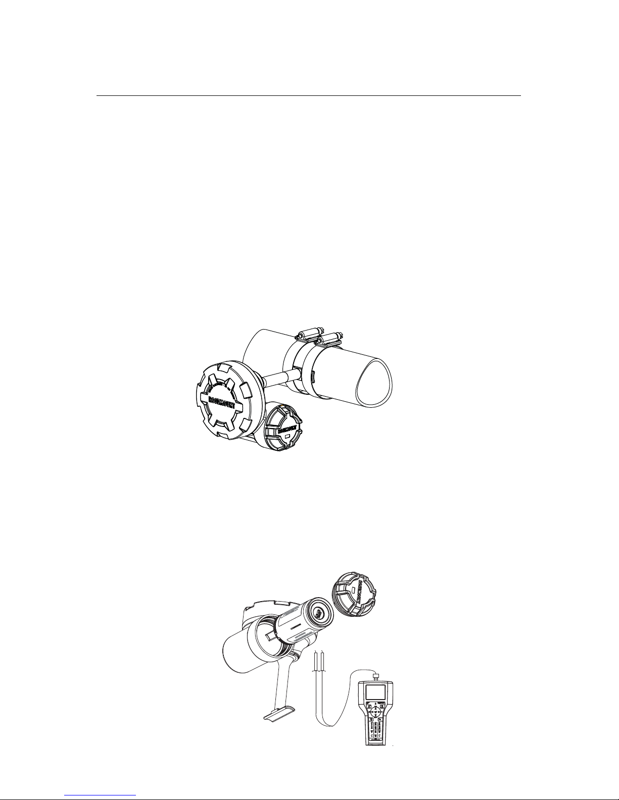
Mounting
1. Locate the 708 on a horizontal section of piping as close as possible to the equipment to
be monitored. Align the waveguide of the transmitter as shown in Figure 3 and Figure 4.
2. The mounting location should be free of foreign matter and corrosion to ensure good
contact between the piping and the waveguide.
3. Tighten each clamp to 90 in-lb (10.2 N-m). Trim the excess clamp band material to
prevent unwanted acoustic noise.
4. If commissioning the device, install the green Power Module (see Figure 5).
5. Ensure that the Power Module cover is fully tightened to prevent moisture ingress. The
lip of the polymer Power Module cover should be in contact with the surface of the
polymer enclosure to ensure a proper seal. Do not over tighten.
Figure 3. Transmitter Alignment
Figure 4. Transmitter Alignment Top View
5
Page 6

Quick Installation Guide
1 in.
00825-0200-4708, Rev AD
Rosemount 708
Figure 5. Power Module Installation
NOTE:
Wireless devices should be powered up in order of proximity from the Smart Wireless
Gateway, beginning with the closest device to the Smart Wireless Gateway. This will
result in faster network formation.
April 2012
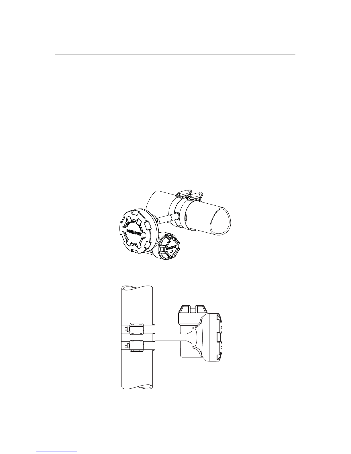
Mounting Considerations
1. Mounting bands should be inspected periodically and retightened if necessary. Some
loosening may occur after initial installation due to thermal expansion/contraction.
2. The waveguide must be in direct contact with the pipe.
3. Insulate process piping to minimize ambient temperature effects (see Figure 6).
Insulation thickness over the top of the waveguide foot should not exceed 1-in (2.54 cm).
4. For best results, mount the transmitter within 6 in. (15.24 cm) of the equipment to be
monitored.
5. The stainless steel mounting bands could be affected by stress corrosion and potentially
fail when in the presence of chlorides.
6. The transmitter should be installed such that steam or other high temperature fluids do
not directly impinge the housing of the device.
7. If installing the device on a steam trap, the device should be installed on the upstream
side of the trap.
Figure 6. Piping, Insulation Side View
6
Page 7

Quick Installation Guide
STEP 2: DEVICE NETWORK CONFIGURATION
00825-0200-4708, Rev AD
April 2012
In order to communicate with the Smart Wireless Gateway, and ultimately the Information
System, the transmitter must be configured to communicate with the wireless network. This
step is the wireless equivalent of connecting wires from a transmitter to the host system.
Using a Field Communicator or AMS, enter the Network ID and Join Key so that they
match the Network ID and Join Key of the gateway and other devices in the network. If the
network ID and join key are not the same as the Gateway, the acoustic transmitter will not
communicate with the network. The Network ID and Join Key may be obtained from the
Smart Wireless Gateway on the Setup>Network>Settings page on the web server, shown
in Figure 7.
Figure 7. Gateway Network Settings
Rosemount 708
AMS
Right click on the acoustic transmitter and select Configure. When the menu opens, select
Join Device to Network and follow the method to enter the Network ID and Join Key.
Field Communicator
The Network ID and Join Key may be changed in the wireless device by using the following
Fast Key sequence. Set both Network ID and Join Key.
Function Key Sequence Menu Items
Join Device to
Network
2, 1, 2
Network ID, Set Join Key
7
Page 8

Rosemount 708
STEP 3: VERIFY OPERATION
Quick Installation Guide
00825-0200-4708, Rev AD
April 2012
There are three ways to verify operation: using the Field Communicator, using the Smart
Wireless Gateway’s integrated web interface, or by using AMS
or AMS Device Manager.
If the Rosemount 708 was configured with the Network ID and Join Key, and sufficient time
has passed, the transmitter will be connected to the network. If Network ID and Join Key
were not configured, please reference Troubleshooting on page 9.
NOTE
It may take several minutes for the device to join the network.
®
Suite Wireless Configurator
Field Communicator
For HART Wireless transmitter communication, a 708 DD is required. To obtain the latest
DD, visit the Emerson Process Management Easy Upgrade site at:
http://www2.emersonprocess.com/en-US/documentation/deviceinstallkits. The
communication status may be verified in the wireless device using the following Fast Key
sequence.
Function Key Sequence Menu Items
Communications 3, 4 Join Status, Wireless Mode, Join Mode,
Number of Available Neighbors, Number of
Advertisements Heard, Number of Join
Attempts
Smart Wireless Gateway
Using the Smart Wireless Gateway’s integrated web interface, navigate to the Explorer
page as shown in Figure 8. Locate the device in question and verify all status indicators are
good (green).
Figure 8. Smart Wireless Gateway Explorer page
8
Page 9

Quick Installation Guide
00825-0200-4708, Rev AD
April 2012
Rosemount 708
AMS® Suite Wireless Configurator
When the device has joined the network, it will appear in the Device Manager as illustrated
in Figure 9. For HART Wireless transmitter communication, a 708 DD is required. To obtain
the latest DD, visit the Emerson Process Management Easy Upgrade site at:
http://www2.emersonprocess.com/en-US/documentation/deviceinstallkits.
Figure 9. Device Manager
NOTE
SteamLogic software is provided for viewing steam trap status. Refer to the manual
on the CD for more information.
Troubleshooting
If the device is not joined to the network after power up, verify the correct configuration of the
Network ID and Join Key, and that Active Advertising has been enabled on the Smart
Wireless Gateway. The Network ID and Join Key in the device must match the Network ID
and Join Key of the Gateway.
The Network ID and Join Key may be obtained from the Gateway on the
Setup>Network>Settings page of the web server (see Figure 10 on page 9). The Network
ID and Join Key may be changed in the wireless device by following the Fast Key sequence
shown below.
Function Key Sequence Menu Items
Join Device to
Network
Figure 10. Smart Wireless Gateway Network Settings
2, 1, 2 Network ID, Set Join Key
9
Page 10

Quick Installation Guide
00825-0200-4708, Rev AD
Rosemount 708
April 2012
Field Communicator Use
NOTE
In order to communicate with a Field Communicator, power the 708 by connecting the
Power Module. For more information on the Power Module, refer to the Power Module
product data sheet (Document No 00813-0100-4701).
Table 1 includes Fast Key sequences frequently used to interrogate and configure the
device. For additional information, refer to the 708 product manual (Document No.
00809-0100-4708).
Table 1. 708 Fast Key Sequence
Function Key Sequence Menu Items
Device Information 2, 2, 5 Tag, Long Tag, Descriptor, Message, Date, Country, SI
Guided Setup 2, 1 Basic Setup, Join Device to Network, Configure Update
Manual Setup 2, 2 Wireless, Sensor, HART, Security, Device Information,
Wireless 2, 2, 1 Network ID, Join Device to Network, Broadcast
Unit Control
Rates, Alert Setup
Power
Information
Figure 11. Field Communicator Connections
10
Page 11

Quick Installation Guide
00825-0200-4708, Rev AD
April 2012
Rosemount 708
PRODUCT CERTIFICATIONS
Approved Manufacturing Locations
Rosemount Inc. – Chanhassen, Minnesota, USA
Emerson Process Management GmbH & Co. - Karlstein, Germany
Emerson Process Management Asia Pacific Private Limited - Singapore
European Union Directive Information
The EC Declaration of Conformity for all applicable European directives for this product can
be found on www.rosemount.com. A hard copy may be obtained by contacting your local
sales representative.
ATEX Directive (94/9/EC)
Emerson Process Management complies with the ATEX Directive.
Electro Magnetic Compatibility (EMC) (2004/108/EEC)
EN 61326-1; 2006
EN 61326-2-3; 2006
Radio and Telecommunications Terminal Equipment Directive (R&TTE)
(1999/5/EC)
Emerson Process Management complies with the R&TTE Directive.
Te lecommunication Compliance
All wireless devices require certification to ensure that they adhere to regulations regarding
the use of the RF spectrum. Nearly every country requires this type of product certification.
Emerson is working with governmental agencies around the world to supply fully compliant
products and remove the risk of violating country directives or laws governing wireless
device usage.
FCC and IC
This device complies with Part 15 of the FCC Rules. Operation is subject to the following
conditions: This device may not cause harmful interference. This device must accept any
interference received, including interference that may cause undesired operation.
This device must be installed to ensure a minimum antenna separation distance of 20 cm
from all persons.
Ordinary Location Certification for FM Approvals
As standard, the transmitter has been examined and tested to determine that the design
meets basic electrical, mechanical, and fire protection requirements by FM Approvals, a
nationally recognized testing laboratory (NRTL) as accredited by the Federal Occupational
Safety and Health Administration (OSHA).
11
Page 12

Quick Installation Guide
00825-0200-4708, Rev AD
Rosemount 708
Hazardous Locations C er tificates
North American Certifications
FM Approvals
I5 Intrinsically Safe
Intrinsically Safe for Class I, Division 1, Groups A, B, C, and D
Zone Marking: Class I, Zone 0, AEx ia llC
Temperature Codes T4 (T
Ambient temperature limits: -40 to 70 °C
For use with SmartPower Solutions, model number 701PGN green power module only.
Enclosure Type 4X / IP66/67
Special Conditions for Safe Use (X):
1. The Rosemount 708 Wireless Acoustic Transmitter shall only be used with the
SmartPower Solutions, model number 701PGN green power module.
2. Potential Electrostatic charging Hazard – See Instructions.
Standards:
FM3600:1998
FM3610:2010
ANSI/NEMA 250
ANSI/IEC60529:2004
= -40 to 70 °C)
amb
April 2012
CSA International
I6 CSA Intrinsically Safe
Certificate No: 2439890
Applicable Standards: CSA std. C22.2 no. 142-M1987, CSA Std. C22.2 No. 157-92
Intrinsically Safe for Class I, Division 1, Groups A, B, C, and D
T3C (-40 °C T
70 °C)
amb
Intrinsically safe when installed according to Rosemount Drawing 00708-1001
For use with SmartPower Solutions, model number 701PGN green power module only.
Enclosure Type 4X, IP66/67
European Certifications
I1 ATEX Intrinsic Safety
Certificate No.: BASEEFA11ATEX0174X II 1G
Ex ia IIC T4 Ga (T
= -40 °C T
a
70 °C)
amb
IP66/67
For use with SmartPower Solutions, model number 701PGN green power module only.
118 0
Special Conditions for Safe Use (X):
1.The engineered polymer enclosure of the Rosemount 708 may constitute a potential
electrostatic ignition risk and must not be rubbed or cleaned with a dry cloth.
Standards:
EN60079-0:2009
EN60079-11:2007
12
Page 13

Quick Installation Guide
00825-0200-4708, Rev AD
April 2012
IECEx System Certifications
I7 IECEx Intrinsic Safety
Certificate No.: IECExBAS 11.0091X
Ex ia IIC T4 Ga (T
= -40 °C T
a
70 °C)
amb
IP66/67
For use with SmartPower Solutions, model number 701PGN green power module only.
Special Conditions for Safe Use (X):
1.The engineered polymer enclosure of the Rosemount 708 may constitute a potential
electrostatic ignition risk and must not be rubbed or cleaned with a dry cloth.
Standards:
IEC60079-0:2007-10
IEC60079-11:2006
Rosemount 708
13
Page 14

Rosemount 708
EC Declaration of Conformity
No: RMD 1084 Rev. C
We,
Rosemount Inc.
8200 Market Boulevard
Chanhassen, MN 55317-6985
USA
declare under our sole responsibility that the product,
Model 708 Wireless Acoustic Transmitter
manufactured by,
Rosemount Inc.
12001 Technology Drive
and
8200 Market Boulevard
Eden Prairie, MN 55344-3695 Chanhassen, MN 55317-9687
USA USA
to which this declaration relates, is in conformity with the provisions of the European
Community Directives, including the latest amendments, as shown in the attached schedule.
Assumption of conformity is based on the application of the harmonized standards and, when
applicable or required, a European Community notified body certification, as shown in the
attached schedule.
(signature)
Timothy Layer
(name - printed)
October 11, 2011
(date of issue)
Vice President Global Quality & Customer Care
(function name - printed)
Quick Installation Guide
00825-0200-4708, Rev AD
April 2012
14
Page 15

Quick Installation Guide
EC Declaration of Conformity
No: RMD 1084 Rev. C
File ID: 708 CE Marking Page 2 of 3
EMC Directive (2004/108/EC)
All Models with ”Operating Frequency and Protocol Code 3”
EN 61326-2-3:2006
R&TTE Directive (1999/5/EC)
All Models with ”Output Code X” and ”Operating Frequency and Protocol Code 3”
EN 301 489-17: V2.1.1 (2009-05)
EN 61010-1: 2001 (Second Addition)
EN 300 328 V 1.7.1 (2006-10)
ATEX Directive (94/9/EC)
Model 708
Certificate: Baseefa11ATEX0174X
Intrinsically Safe - Group II Category 1 G
Ex ia IIC T4 Ga (Ta = -40°C to +70°C)
Harmonized Standards Used:
EN60079-0:2009; EN60079-11:2007
00825-0200-4708, Rev AD
April 2012
Rosemount 708
15
Page 16

Rosemount 708
EC Declaration of Conformity
No: RMD 1084 Rev. C
File ID: 708 CE Marking Page 3 of 3
ATEX Notified Bodies for EC Type Examination Certificate
Baseefa. [Notified Body Number: 1180]
Rockhead Business Park
Staden Lane
Buxton, Derbyshire
SK17 9RZ United Kingdom
ATEX Notified Body for Quality Assurance
Baseefa. [Notified Body Number: 1180]
Rockhead Business Park
Staden Lane
Buxton, Derbyshire
SK17 9RZ United Kingdom
Quick Installation Guide
00825-0200-4708, Rev AD
April 2012
16
 Loading...