

Page 1

Rosemount™ 6888A
O2 Combustion Flue Gas Transmitter
Reference Manual
00809-0100-4890, Rev AA
July 2018
Page 2

Essential instructions
Read this page before proceeding!
EmersonTM designs, manufactures, and tests its products to meet many national and international standards. Because these
instruments are sophisticated technical products, you must properly install, use, and maintain them to ensure they continue to
operate within their normal specifications. The following instructions must be adhered to and integrated into your safety program
when installing, using, and maintaining Emerson products. Failure to follow the proper instructions may cause any one of the
following situations to occur: loss of life, personal injury, property damage, damage to this instrument, and warranty invalidation.
• Read all instructions prior to installing, operating, and servicing the product.
• If you do not understand any of the instructions, contact your Emerson representative for clarification.
• Follow all warnings, cautions, and instructions marked on and supplied with the product.
• Inform and educate your personnel in the proper installation, operation, and maintenance of the product.
• Install equipment as specified in the installation instructions of the appropriate instruction manual and per applicable local
and national codes. Connect all products to the proper electrical and pressure sources.
• To ensure proper performance, use qualified personnel to install, operate, update, program, and maintain the product.
• When replacement parts are required, ensure that qualified people use replacement parts specified by Emerson.
Unauthorized parts and procedures can affect the product's performance, place the safe operation of your process at risk,
and VOID YOUR WARRANTY. Look-alike substitutions may result in fire, electrical hazards, or improper operation.
• Ensure that all equipment doors are closed and protective covers are in place, except when maintenance is being performed
by qualified people, to prevent electrical shock and personal injury.
NOTICE
The information contained in this document is subject to change without notice.
NOTICE
The Field Communicator must be upgraded to System Software 2.0 with graphic license for operation with the RosemountTM 6888A
O2 Transmitter. The AMS software must be upgraded to AMS 8.0 or above. Contact Emerson's Global Service Center (GSC) at
+1-800-833-8314 to upgrade the Field Communicator software to System Software 2.0 with graphic license.
Preface
The purpose of this manual is to provide information concerning components, functions, installation, and maintenance of the
Rosemount 6888A O2 Transmitter.
Some sections may describe equipment not used in your configuration. You should become thoroughly familiar with the operation
of this module before operating it. Read this reference manual completely.
Symbols
Earth (ground) terminal
Protective conductor terminal
Risk of electrical shock
Refer to reference manual.
The following definitions apply to Warnings, Cautions, and Notices found throughout this publication.
WARNING!
Highlights an operation or maintenance procedure, practice, condition, statement, etc., which if not strictly observed, could result in
injury, death, or long-term health hazards of personnel.
Page 3

CAUTION!
Highlights an operation or maintenance procedure, practice, condition, statement, etc., which if not strictly observed, could result in
damage to or destruction of equipment or loss of effectiveness.
NOTICE
Highlights an essential operating procedure, condition, or statement.
Overview
The 6888A is Rosemount's latest in-situ probe offering intended for combustion flue gas service. Similar to our previous World Class
and Oxymitter probes, there is no sampling system. The sensing cell is mounted to the end of a probe (18 in., 3 ft, 6 ft, 9 ft, or 12 ft
long) that is directly inserted into the flue gas stream.
The sensing cell is of similar design to the World Class and Oxymitter cells, using the zirconium oxide sensing principle. The cell is
heated and maintained at 736 °C (1357 °F) setpoint and generates a logarithmic MV signal proportional to the partial pressure
difference of oxygen between the reference side of the cell (usually instrument air at 20.95% O2) and the process side of the cell
(usually combustion flue gases). For more information on sensing cell operation, see Chapter 4.
Technical support hotline
For assistance with technical problems, please call the Customer Support Center (CSC).
Phone: 1-800-433-6076 1-440-914-1261
In addition to the CSC, you may also contact Field Watch. Field Watch coordinates Emerson's field service throughout the US and
abroad.
Phone: 1-800-654-RSMT (1-800-654-7768)
Email: Gas.CSC@emerson.com
Web: www.Emerson.com/RosemountGasAnalysis
Page 4

Page 5

Contents
Contents
Chapter 1 Description and specifications ........................................................................................1
1.1 Component checklist ...................................................................................................................1
1.2 Technical support hotline ............................................................................................................ 2
1.3 System overview ..........................................................................................................................3
1.4 System configurations ................................................................................................................. 3
1.4.1 Transmitter probe, only .................................................................................................3
1.4.2 Standard housing transmitter probe plus Rosemount 6888Xi Electronics ......................3
1.4.3 Transmitter probe and Rosemount 6888Xi with flame safety interlock ......................... 4
1.4.4 Transmitter probe with integral autocal, Rosemount 6888Xi, and HART
communications ........................................................................................................... 4
1.4.5 Transmitter probe with integral autocal and FOUNDATION™ Fieldbus (FF)
communications ........................................................................................................... 4
1.4.6 Direct replacement (DR) probe with traditional architecture Rosemount 6888Xi
electronics .................................................................................................................... 5
1.4.7 Wireless capability ........................................................................................................ 5
1.4.8 Automatic calibration ....................................................................................................5
1.4.9 Communication options ............................................................................................... 6
1.5 Probe options .............................................................................................................................. 8
1.5.1 Diffusion elements ........................................................................................................8
1.6 Rosemount 6888A product matrix .............................................................................................10
1.7 Rosemount 6888Xi product matrix ............................................................................................12
1.8 Transmitter/DR probe specifications ..........................................................................................14
®
Chapter 2 Install ...........................................................................................................................17
2.1 System considerations ...............................................................................................................18
2.2 Mechanical installation .............................................................................................................. 19
2.2.1 Install probe ................................................................................................................ 20
2.2.2 Variable insertion ........................................................................................................ 24
2.3 Electrical installation ..................................................................................................................26
2.3.1 Wiring for Rosemount 6888 Transmitter probe only (no Rosemount 6888Xi
Electronics) ................................................................................................................. 26
2.3.2 Standard housing transmitter probe plus Rosemount 6888Xi Electronics ....................28
2.3.3 Transmitter probe with single-channel Xi and flame safety interlock ...........................32
2.3.4 Transmitter probe with integral autocal and HART communications ...........................35
2.3.5 Wire the Rosemount 6888A Transmitter probe with integral autocal and FOUNDATION
Fieldbus communications ........................................................................................... 37
2.3.6 Wire the traditional architecture system with direct replacement probe (no electronics
inside) ......................................................................................................................... 38
2.3.7 Wire the traditional architecture cable connections .................................................... 40
2.4 Pneumatic installation ............................................................................................................... 42
2.4.1 Reference air package ................................................................................................. 42
2.4.2 Calibration gas ............................................................................................................ 45
Chapter 3 Configuration, startup, and operation .......................................................................... 47
3.1 Power up Rosemount 6888 Transmitter without Rosemount 6888Xi .........................................47
3.2 Power up the Rosemount 6888 Transmitter with single/dual channel or single channel and flame
safety interlock Rosemount 6888Xi ........................................................................................... 48
™
Reference Manual i
Page 6

Contents
3.3 Power up the Rosemount 6888 direct replacement probe (no electronics inside) with traditional
architecture Rosemount 6888Xi ................................................................................................ 48
3.4 Rosemount 6888Xi Quick Start Wizard ...................................................................................... 49
3.5 Re-initiating Rosemount 6888Xi wizard ..................................................................................... 50
3.6 Calibration .................................................................................................................................50
3.6.1 Manual/semi-automatic calibration ............................................................................ 50
3.6.2 Fully automatic calibration ..........................................................................................51
3.6.3 Other features associated with calibration .................................................................. 52
3.7 Startup ...................................................................................................................................... 75
3.7.1 Error conditions ...........................................................................................................75
3.8 System parameter descriptions ................................................................................................. 76
3.9 Parameter setup ........................................................................................................................ 79
3.9.1 Test gas values ............................................................................................................ 79
3.9.2 Set test gas times ........................................................................................................79
3.9.3 Track output during calibration ...................................................................................80
3.9.4 Configure analog output .............................................................................................81
3.10 Calibrate ....................................................................................................................................81
3.10.1 Calibration procedure ................................................................................................. 82
3.10.2 Calibration log .............................................................................................................83
3.10.3 Reset calibration ......................................................................................................... 83
3.11 D/A trim .....................................................................................................................................84
Chapter 4 Troubleshooting .......................................................................................................... 87
4.1 Overview ................................................................................................................................... 87
4.2 General ......................................................................................................................................89
4.2.1 Grounding ...................................................................................................................89
4.2.2 Electrical noise ............................................................................................................ 89
4.2.3 Electrostatic discharge ................................................................................................89
4.3 Alarm indications .......................................................................................................................90
4.4 Identifying and correcting fault indications ................................................................................91
4.5 Calibration passes, but still reads incorrectly ..............................................................................92
4.5.1 Probe passes calibration, O2 still reads high .................................................................93
4.5.2 Probe passes calibration, O2 still reads low .................................................................. 94
4.5.3 How do I detect a plugged diffuser? ............................................................................ 94
4.5.4 Can I calibrate a badly plugged diffuser? ......................................................................94
Chapter 5 Maintenance and service ..............................................................................................97
5.1 Overview ................................................................................................................................... 97
5.2 Maintenance intervals ................................................................................................................97
5.3 Calibrate ....................................................................................................................................98
5.3.1 Manual calibration ...................................................................................................... 98
5.3.2 Automatic calibration ................................................................................................. 98
5.4 Repair ........................................................................................................................................ 98
5.4.1 Remove and replace probe ..........................................................................................99
5.4.2 Replace transmitter board ...........................................................................................99
5.4.3 Replace DR terminal board ........................................................................................102
5.4.4 Heater strut replacement ..........................................................................................103
5.4.5 Cell replacement .......................................................................................................105
5.4.6 Diffusion element replacement .................................................................................108
5.4.7 Blind cover replacement ............................................................................................110
Chapter 6 Replacement parts ..................................................................................................... 113
Chapter 7 Optional accessories ...................................................................................................115
ii Rosemount 6888A
Page 7

Contents
7.1 Asset Management Solutions (AMS) ........................................................................................ 115
7.2 By-Pass Packages ..................................................................................................................... 115
7.3 Rosemount SPS 4001B Single Probe Autocalibration Sequencer ..............................................116
7.4 Rosemount IMPS 4000 Intelligent Multiprobe Test Gas Sequencer .......................................... 117
7.5 O2 calibration gas .................................................................................................................... 118
7.6 Optional Rosemount OxyBalance Display and Averaging System .............................................119
Appendices and reference
Appendix A Rosemount™ 6888 product certifications ....................................................................121
A.1 European Directive information ...............................................................................................121
A.2 Ordinary location certification ................................................................................................. 121
A.3 Installing equipment in North America .................................................................................... 121
A.4 Rosemount™ 6888A In-Situ Oxygen Transmitter for General Purpose Locations .......................121
A.4.1 USA ...........................................................................................................................121
A.4.2 Canada ......................................................................................................................122
A.4.3 Europe ...................................................................................................................... 122
A.5 Rosemount™ 6888Xi Digital Transmitter for General Purpose Locations .................................. 122
A.5.1 USA ...........................................................................................................................122
A.5.2 Canada ......................................................................................................................122
A.6 Rosemount™ SPS4001B and IMPS4000 Autocalibration Devices for General Purpose
Locations ................................................................................................................................. 123
A.6.1 USA/Canada ..............................................................................................................123
Appendix B Safety data ................................................................................................................. 125
B.1 Safety instructions for the wiring and installation of this apparatus ..........................................125
Reference Manual iii
Page 8

Contents
iv Rosemount 6888A
Page 9

Description and specifications
1 Description and specifications
1.1 Component checklist
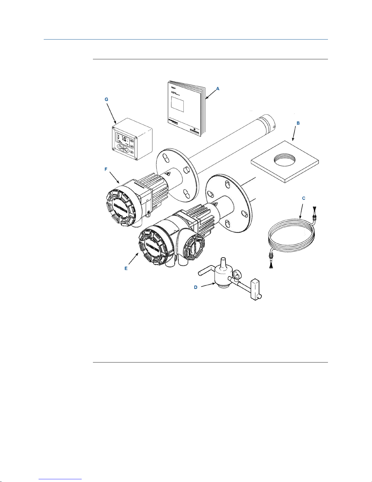
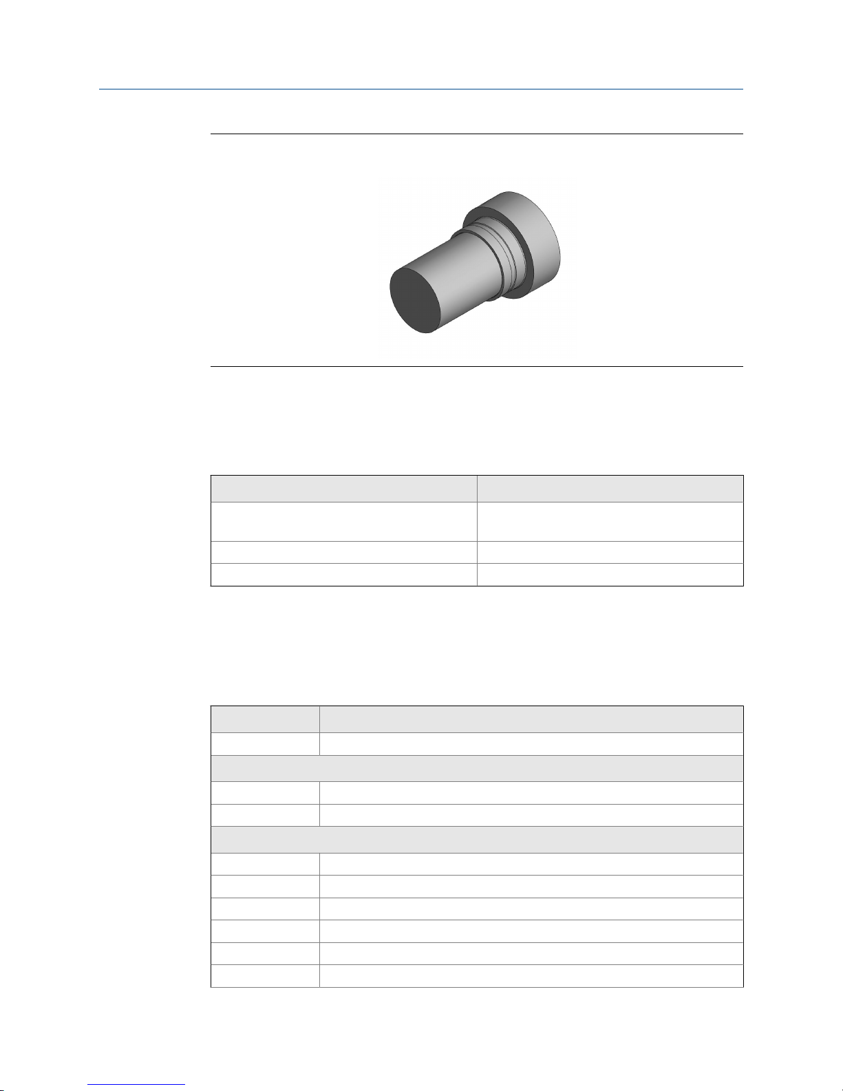
A typical Rosemount™ 6888A O2 Combustion Flue Gas Transmitter should contain the
items shown in Figure 1-1. A complete Oxygen Analyzer system includes some or all of the
equipment shown. However, this manual describes the Rosemount 6888A Transmitter
only.
Also, use the product matrix (Section 1.6) at the end of this section to compare your order
number against your unit. The first part of the matrix defines the model. The last part
defines the various options and features of the Rosemount 6888A. Ensure the features and
options specified by your order number are on or included with the unit.
Reference Manual 1
Page 10
Description and specifications
Typical System PackageFigure 1-1:
A. Quick start guide
B. Optional mounting or adapter plate
C. Optional traditional architecture cable
D. Optional reference and calibration gas accessories
E. 6888A integral autocal housing
F. 6888A probe with standard terminations/electronics housing
G. Optional 6888Xi Advanced Electronics
1.2
2 Rosemount 6888A
Technical support hotline
For assistance with technical problems, please call the Customer Support Center (CSC).
• 1-RAI-AND-U (1-855-724 2638)
• 1-440-914-1261
Page 11

In addition to the CSC, you may also contact Field Watch. Field Watch coordinates
Emerson's field service throughout the US and abroad.
• 1-800-654-RSMT (1-800-654-7768)
Emerson may also be reached via the Internet through email and the World Wide Web.
• Email: Gas.CSC@Emerson.com
• World Wide Web: www.Emerson.com/RosemountGasAnalysis
1.3 System overview
The 6888 is Rosemount's latest combustion flue gas oxygen analyzer. This product is
intended for measuring the flue gases resulting from any combustion process. It uses the
same heated sensing technology as the O2 sensors found in most automobiles. Contact
Rosemount's technical support group at 800-433-6076 for any applications other than
measuring combustion flue (exhaust) gases.
This product uses an in-situ sensor, i.e., the sensor is placed at the end of a probe, and the
probe extends directly into the flue gas duct or stack at a given length. The sensor is like a
thermocouple, generating its own millivolt signal based on the differences between a
reference gas (ambient or instrument air - always 20.95% O2) and the flue gases being
measured. There are several different arrangements of probes, electronics, and features
that are explained below and in the wiring diagrams.
Description and specifications
An optional Rosemount 6888Xi with HART® communication provides a convenient
operator interface for setup, calibration, and diagnostics. HART communication is still
present when using the Rosemount 6888Xi.
1.4
System configurations
1.4.1 Transmitter probe, only
The Rosemount 6888 probe has the electronics in the blue housing that controls the
heater temperature and also amplifies the raw O2 millivolt signal to a linear 4-20 mA. The
4-20 mA signal lines can be run directly to the control room and also power the transmitter
electronics. As with most other Rosemount transmitters, measuring pressure,
temperature, and flow setup is conducted through HART communications via a 475
handheld communicator or via Asset Management Solutions (AMS).
1.4.2
Standard housing transmitter probe plus Rosemount
6888Xi Electronics
The Rosemount 6888Xi Electronics serve as a local operator interface unit with a back-lit
display and keypad. It is capable of two channels, serving two Rosemount 6888 probes.
The Rosemount 6888Xi also carries these optional advanced features:
• Fully automatic calibration. Requires Xi O2 Cal Autocalibration system
Reference Manual 3
Page 12

Description and specifications
• Loss of flame contact for powering down the heater in the event of a flame-out
• Heaterless operation at process temperatures above 550 °C (1022 °F). This feature
• Plugged diffuser diagnostic operates by measuring the return-to-process rate after
• Stochiometer - If a furnace goes into a reducing condition (zero % O2), this feature
• Programmable reference - Permits more accurate readings at near-ambient O
• A cal check capability. New calibration values are not automatically stored after a
• Tolerance check that will alarm if the wrong test gases are being used or if a bottle
condition in a furnace.
will also permit operation above the heater setpoint of 736 °C (1357 °F). Sensing cell
life will be shortened by operation above 800 °C (1472 °F), however.
calibration gas has been stopped. This feature also includes auto gas switching when
the reading settles out versus waiting for configured gas flow time to expire.
will determine how far.
2
levels (20.95% O2).
calibration. An accept/reject calibration feature can be enabled or disabled so that
the techniciean or operator can decice to accept or reject a potentially large change
in calibration values.
runs out in the middle of a calibration. Take care to ensure gas 1 and gas 2
calibration gases are properly configured if the tolerance check feature is enabled.
1.4.3 Transmitter probe and Rosemount 6888Xi with flame
safety interlock
A flame safety interlock by Emerson is available for heater power disconnect whenever
there is a loss of the process flame or a heater runaway condition (heater overtemperature) in the O2 probe. This input is internally powered by the Rosemount 6888Xi
and is actuated via a dry contact output from your flame scanner. A closed contact
indicates a flame is present. An open contact indicates a loss of flame. This feature is also
available with the integral autocal housing.
1.4.4
Transmitter probe with integral autocal, Rosemount
6888Xi, and HART® communications
This probe contains gas-switching solenoids so that the Rosemount 6888Xi electronics can
control the introduction of calibration gases. Calibrations can be initiated via a calibration
recommended diagnostic, time since last calibration, manually via external dry contact,
HART communications, or from the Rosemount 6888Xi local operator interface keypad.
The integral autocal feature can only be implemented when the probe is used with a
Rosemount 6888Xi.
1.4.5
Transmitter probe with integral autocal and
FOUNDATION™ Fieldbus (FF) communications
This probe contains gas-switching solenoids that can control the introduction of
calibration gases for calibration. Calibrations can be initiated automatically via a calibration
recommended diagnostic, time since last calibration, manually via the optional
4 Rosemount 6888A
Page 13

Description and specifications
Rosemount 6888Xi keypad, FF communications via the 475 communicator, or AMS
console. Unlike the HART transmitter electronics, the FF version can execute automatic
calibrations either with or without the optional Rosemount 6888Xi electronics. Likewise,
advanced features can be implemented either with or without the optional Rosemount
6888Xi.
1.4.6 Direct replacement (DR) probe with traditional
architecture Rosemount 6888Xi electronics
Here there are no electronics inside the probe head, so the raw sensor signals for the
heater thermocouple and zironium oxide O2 sensor are sent to a remote Rosemount
6888Xi Electronics. The Rosemount 6888 traditional architecture electronics will also
directly apply power to the probe heater in order to maintain the correct sensor
temperature. This arrangement calls for a 7-conductor cable to carry this power and the
sensor signals. Maximum length for the cable is 200 feet. This probe will also operate on
previous Westinghouse/Rosemount electronics (World Class and Oxymitter), as well as
many competitive electronics.
1.4.7 Wireless capability
1.4.8
Both the transmitter electronics in the head of the probe and the Rosemount 6888Xi
Electronics communicate over HART communications and can implement wireless
communications via Emerson Wireless 775 THUM™ Adapter.
Automatic calibration
Calibrations consist of introducting bottled gases of known value into the probe so that
the electronics can make automatic adjustments to the O2 readings to match the bottled
gas value.
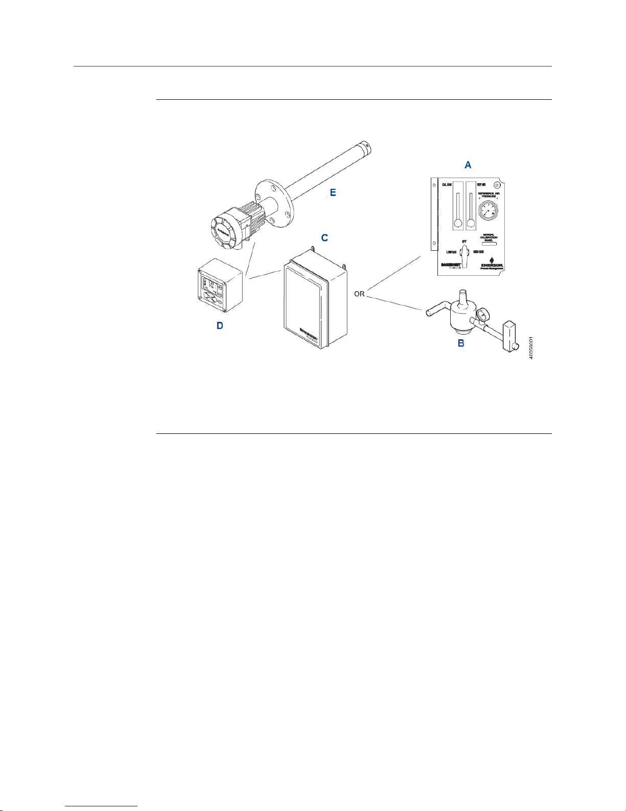
Emerson recommends 0.4% O2 and 8% O2 (balance nitrogen) gases. Never use nitrogen or
instrument air as calibration gases. Flowmeters (for calibration gases) and regulators and
flowmeters (for reference air) are available as loose components, mounted into an
optional manual calibration switching panel or a fully automatic calibration system
(Figure 1-2) where calibration solenoids are switched from the Rosemount 6888Xi
Advanced Electronics. See the Rosemount SPS 4001B Single Probe Autocalibration Sequencer
or Rosemount IMPS 4000 Intelligent Multiprobe Test Gas Sequencer manuals for additional
details.
Reference Manual 5
Page 14
Description and specifications
Figure 1-2:
A. Manual calibration switching panel
B. Reference air set
C. Rosemount SPS 4001B or Rosemount IMPS 4000
D. Rosemount 6888Xi Advanced Electronics
E. Rosemount 6888A O2 Transmitter
Rosemount 6888A with Rosemount 6888Xi Advanced Electronics and
Autocalibration Sequencer
1.4.9
Communication options
A customer-supplied 375/475 Field Communicator and/or the optional Rosemount 6888Xi
Advanced Electronics accomplish Rosemount 6888A communications. Graphic displays
are available via the optional Rosemount OxyBalance Display and Averaging System.
Data communications
You can configure and diagnostically troubleshoot the Rosemount 6888A in one of two
ways:
1. Using the optional Rosemount 6888Xi Advanced Electronics allows local
communication with the electronics. The Rosemount 6888Xi also offers the
following optional advanced features:
• Fully automatic calibration.
• Optional flame safety interface (single probe version only).
• High temperature operation [above 700 °C (1292 °F) standard temperature].
• Stoichiometer feature provides the ability to indicate O2 efficiency when the
combustion process goes into reducing conditions (0% O2).
• Programmable reference provides enhanced accuracy when measuring at or
near O2 level (20.95% O2).
6 Rosemount 6888A
Page 15

Description and specifications
• Plugged diffuser diagnostic to detect fouled diffuser.
2. Using the HART interface, the Rosemount's 6888A's 4-20 mA output line transmits
an analog signal proportional to the oxygen level. The HART output is superimposed
on the 4-20 mA output line. This information can be accessed through the following:
• Rosemount 375/475 Field Communicator: The handheld communicator requires
device description (DD) software specific to the Rosemount 6888A. The DD
software is supplied with many 375/475 units, but can also be programmed into
existing units at most Emerson service offices. See Chapter 3 for additional
information.
• Personal computer (PC): The use of a personal communicator requires AMS
software available from Emerson.
• Delta V and Ovation Distributed Control System (DCS) with AMS-inside
capability.
3. The Rosemount 6888A can also transmit HART information wirelessly via a wireless
THUM Adapter. The THUM Adapter threads into the Rosemount 6888A conduit port
and converts the 4-20 mA signal to a wireless protocol. All other HART information is
also transmitted.
In addition to the wireless THUM Adapter, a hard wire connection of the 4-20 mA
signal to the DCS may be used at the same time. More detailed information
regarding the application of the THUM Adapter is available in Product Data Sheet
00813-0100-4075.
Note
The 375 field communicator must be upgraded to System Software 2.0 with Graphic License for
operation with the Rosemount 6888A O2 transmitter. The AMS software must be upgraded to AMS
8.0 or above.
Contact Emerson's Global Service Center (GSC) at 1-800-833-8314 to upgrade the 375 field
communicator software to System Software 2.0 with Graphic License.
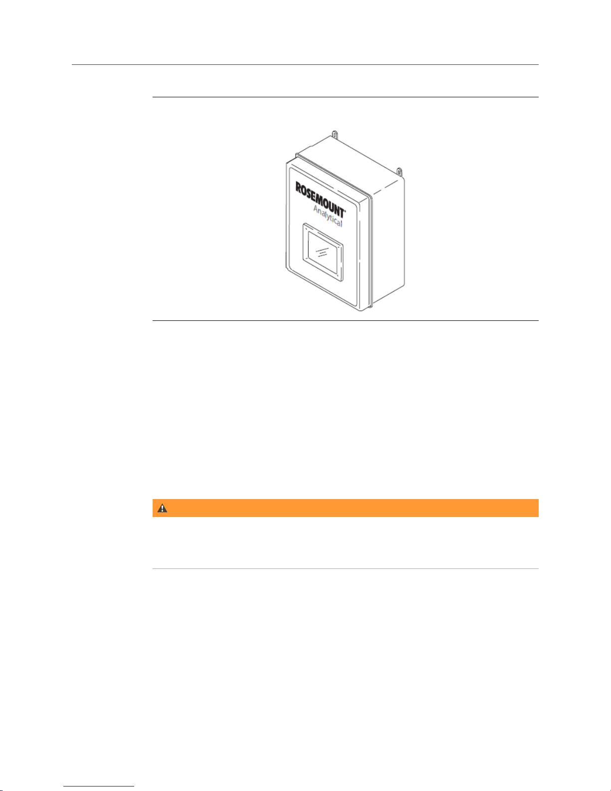
Optional Rosemount OxyBalance Display and Averaging
System
The optional Rosemount OxyBalance Display and Averaging System receives up to eight
4-20 mA signals from individual probes, trends individual outputs, and calculates four
programmable averages as additional 4-20 mA outputs. For more information, call
Rosemount at 1-800-433-6076.
Reference Manual 7
Page 16
Description and specifications
Rosemount OxyBalance SystemFigure 1-3:
1.5 Probe options
1.5.1 Diffusion elements
The Rosemount 6888A is available with one of three diffusion elements fitted to the
process end. The basic diffusers provide for a constant outer probe tube diameter the full
length of the probe. When the Rosemount 6888A is used with an abrasive shield, the
diffuser body has a larger diameter with grooves to accept packing material to seal out fly
ash. The snubber and ceramic diffusers may also be fitted with a flash arrestor to reduce
the possibility of the probe igniting from flammable gases within the process.
WARNING!
FLAME AND EXPLOSION
The diffusers fitted with flash arrestors have been tested to provide a measure of protection in
preventing ignition of flammable gases. They are not intended to provide flame proof or
explosion proof protection for the Rosemount 6888A.
8 Rosemount 6888A
Page 17
Description and specifications
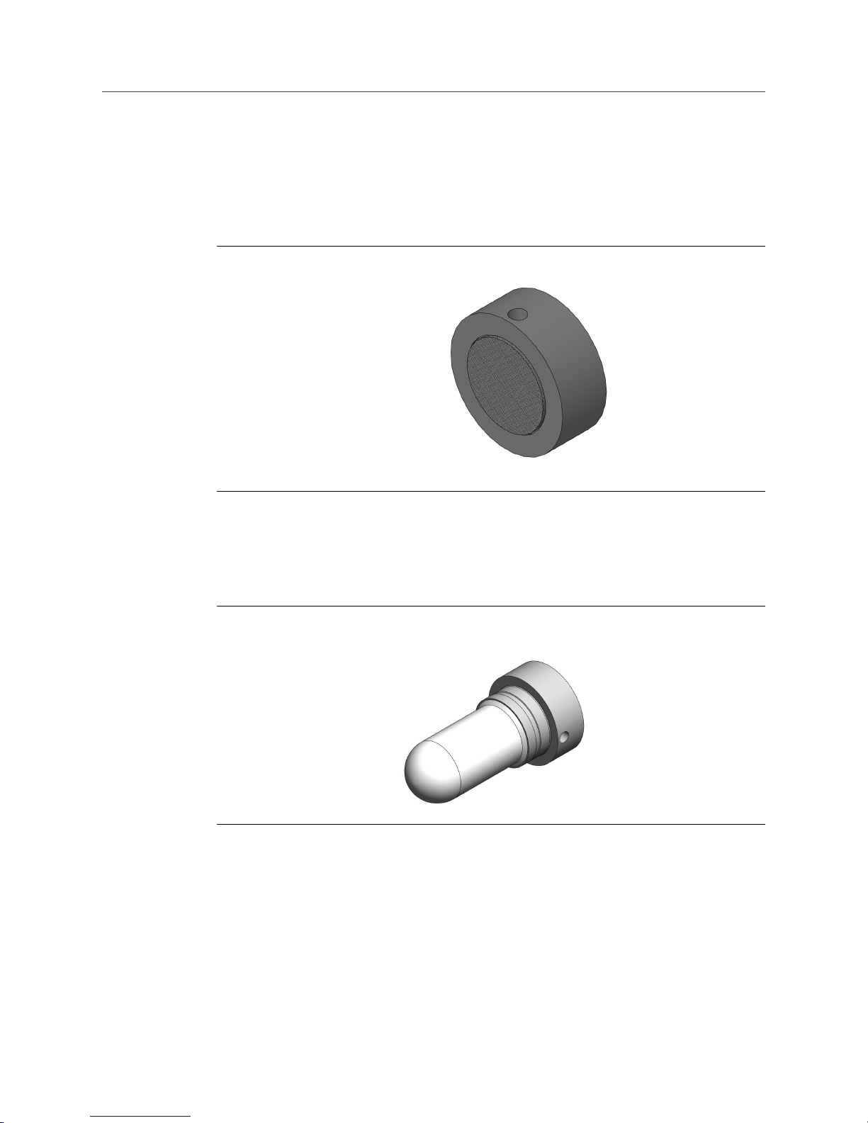
Snubber diffusion assembly
The standard snubber diffusion assembly (Figure 1-4) is satisfactory for most applications;
however, the snubber diffuser should not be used in flue gas temperatures above 400 °C
(752 °F).
Snubber Diffusion AssemblyFigure 1-4:
Ceramic diffusion assembly
The ceramic diffusion assembly (Figure 1-5) is the traditional design for the probe. Used for
over 25 years, the ceramic diffusion assembly provides a greater filter surface area.
Ceramic Diffusion AssemblyFigure 1-5:
Cup-type diffusion assembly
The cup-type diffusion assembly (Figure 1-6) is typically used in high temperature
applications where frequent diffusion element plugging is a problem. The cup-type
difusion assembly is available with a 40 micron, sintered, Hastelloy element.
Reference Manual 9
Page 18
Description and specifications
Hastelloy Cup-Type Diffusion AssemblyFigure 1-6:
1.6 Rosemount 6888A product matrix
Calibration GlassTable 1-1:
Part number Description
1A9919G01 Two disposable calibration gas bottles - 0.4%
and 8% O2, balance nitrogen - 550 liters each.
1A9919G02 Two flow regulators for calibration gas bottles
1A9919G03 Bottle rack
(1) Calibration gas bottles cannot be shipped via air freight.
Compare the configuration matrix below to the model number on the probe tag to
confirm the features present in this specific probe
Rosemount 6888A Product MatrixTable 1-2:
Model Description
6888A O2 Transmitter
Measurement
1OXY Oxygen, standard sensing cell
2OXY Oxygen, acid resistant stochiometric sensing cell
Probe length
1 18 in. probe, standard probe tube
2 18 in. probe, standard probe tube with abrasive shield
3 18 in. probe, abrasion resistant probe tube
4 3 ft probe, standard probe tube
5 3 ft probe, standard probe tube with abrasive shield
6 3 ft probe, abrasion resistant probe tube
(1)
(1)
10 Rosemount 6888A
Page 19

Description and specifications
Rosemount 6888A Product Matrix (continued)Table 1-2:
7 6 ft probe, standard probe tube
8 6 ft probe, standard probe tube with abrasive shield
9 6 ft probe, abrasion resistant probe tube
A 9 ft probe, abrasion resistant probe tube
AA 9 ft probe, abrasion resistant probe tube with abrasive shield
B 12 ft probe, abrasion resistant probe tube
BA 12 ft probe, abrasion resistant probe tube with abrasive shield
Diffuser
1 Snubber 400 °C (752 °F)
1A Snubber with dust shield 400 °C (752 °F) (used with abrasive shield)
1F Snubber with flashback arrestor 400 °C (752 °F)
2 Ceramic 825 °C (1517 °F)
2A Ceramic with dust shield 825 °C (1517 °F) (used with abrasive shield)
2F Ceramic (825 °C) with flashback arrestor 825 °C (1517 °F)
3 Hastelloy 40 µm 705 °C (1292 °F)
3A Hastelloy with dust seal 40 µm 705 °C (1292 °F) *used with abrasive shield)
Housing and electronics
1HT Standard housing, transmitter electronics, HART communications
2HT Integral autocal, transmitter electronics, HART communications
4FF Integral autocal, transmitter electronics, Fieldbus communications
5DR Standard housing, direct replacement, no electronics
6DRY Standard housing, direct replacement, YEW electronics
Mounting plate
00 None
04 New installation - square weld plate with ANSI 2 in. - 150# studs & flange (2.5
in. process hole required)
05 New installation - square weld plate with DIN studs and flange (2.5 in. process
hole required)
06 New installation - variable insertion mount; abrasion resistant probe only
07 New installation - variable insertion mount; mounted to existing OXT/WC
abrasive shield mounts; abrasion resistant probe only
08 Adapter to existing ANSI 3 in. 150# flange
09 Adapter to existing ANSI 4 in. 150# flange
10 Adapter to existing ANSI 6 in. 150# flange
11 Adapter to existing ANSI 3 in. 300# flange
12 Adapter to existing ANSI 4 in. 300# flange
Reference Manual 11
Page 20

Description and specifications
99 Special adapter - provide existing flange dimensions, including thru-hole di-
Manual calibration accessories
00 None
01 Calibration and reference gas flowmeters and reference regulator/filter diffus-
02 Calibration/reference panel
Stoichiometer function -FOUNDATION Fieldbus only (For HART versions, order this feature
with Rosemount 6888Xi Electronics)
0 No
1 Yes
Programmable reference function - FOUNDATION Fieldbus only (For HART versions, order
this feature with Rosemount 6888Xi Electronics)
0 No
1 Yes
Rosemount 6888A Product Matrix (continued)Table 1-2:
ameter
er
1.7
Extended temperature reference function - FOUNDATION Fieldbus only (For HART versions,
order this feature with Rosemount 6888Xi Electronics)
0 No
1 Yes
Diffuser warning function - FOUNDATION Fieldbus only (For HART versions, order this feature
with Rosemount 6888Xi Electronics)
0 No
1 Yes
(1) Probes supplied with flanges with dual ANSI/DIN hole pattern.
Rosemount 6888Xi product matrix
Compare the configuration matrix below to the model number on the probe tag to
confirm the features present in this specific probe.
Model
6888Xi Advanced Electronics
Remote type
1OXY Single channel O
2OXY Single channel O2 with flame safety interlock for heater
3OXY Dual channel O
4OXY Single channel O2 with traditional architecture for 120 V probes
Product description
2
2
(1)
12 Rosemount 6888A
Page 21
Description and specifications
Mounting
00 No Hardware
01 Panel mount kit with gasket
02 2 in. pipe/wall mount kit
Cable
00 No cable
10 6 m (20 ft) cable, use with traditional architecture probe only
11 12 m (40 ft) cable, use with traditional architecture probe only
12 18 m (60 ft) cable, use with traditional architecture probe only
13 24 m (80 ft) cable, use with traditional architecture probe only
14 30 m (100 ft) cable, use with traditional architecture probe only
15 45 m (150 ft) cable, use with traditional architecture probe only
16 60 m (200 ft) cable, use with traditional architecture probe only
Stoichiometer function for O
2
00 No
01 Single channel
02 Dual channel
Programmable reference function for O
2
00 None
01 Single channel
02 Dual channel
Extended Temperature Function for O
2
00 None
01 Single channel
02 Dual channel
Plugged diffuser diagnostics
00 None
01 Single channel
02 Dual channel
(1) The Rosemount 6888Xi does not support World Class 44v probes.
Reference Manual 13
Page 22

Description and specifications
The X-STREAM Xi will support World Class 44v probes.
1.8 Transmitter/DR probe specifications
Measurement SpecificationsTable 1-3:
Net O2 range Variable 0 - 10% to 0 - 50%
(Xi electronics off 0 - 50% O2 range)
Accuracy in oxidizing condition ±0.75% of reading or 0.05% O2, whichever is greater
Lowest detectable limit 0.02% O
Process temperature effect Less than 0.05% O2 from 100 to 700 °C (212 to 1292 °F)
System speed of response to calibration gas Initial response in less than 3 seconds, T∞ in less than 8
seconds. Response to process gas changes vary depending
on velocity and particulate loading of the diffuser.
Calibration validity Presentation of calibration gases matches the bottle value
to within ±0.02% O2.
Accuracy in reducing conditions (requires stoichiometer
feature)
System response in reducing conditions (requires stoichiometer feature)
±10% of reading or 0.1% O2, whichever is greater
Going from oxidizing to reducing -T90 in 120 seconds
Going from reducing to oxidizing -T90 in 30 seconds
2
Environmental specificationsTable 1-4:
Transmitter probe Process-wetted materials are 316L or 304 stainless.
Process temperature limits 0 to 705 °C (32 to 1300 °F)
550 to 825 °C (1022 to 1517 °F) with Xi heaterless operation
(1)
feature
Transmitter electronics housing Low copper aluminum Type 4X/IP66 with reference air ex-
haust port piped to clean, dry area
Ambient temperature limits
-40 to 70 °C (-40 to 158 °F), transmitter
-40 to 85 °C (-40 to 185 °F) as measured by electronics
-40 to 90 °C (-40 to 194 °F), DR probe
Probe electronics ambient temperature limits -40 to 70 °C (-40 to 158 °F)
Temperature limit as measured inside probe electronics -40 to 85 °C (-40 to 185 °F)
DR probe, no electronics inside, ambient temperature limits
Optional Xi electronics
Materials NEMA 4X, polycarbonate material
-40 to 90 °C (-40 to 194 °F)
14 Rosemount 6888A
Page 23
Description and specifications
Environmental specifications (continued)Table 1-4:
General purpose certifications
Xi ambient temperature limits -20 to 50 °C (-4 to 122 °F)
Xi temperature limits as measured inside the electronics
-20 to 70 °C (-4 to 158 °F)
housing
(1) Reduced cell life can be expected if operated continously at temperatures above 705 °C (1300 °F). Optional bypass and jacket
accessories permit operation to 1050 °C (1922 °F).
Installation specifications - probeTable 1-5:
Probe mounting flange Vertical or horizontal - 2 in. 150# (121 m (4.75 in.) bolt cir-
cle)
Note
Flanges are flat-faced and for mounting only. Flanges are
not pressure-rated. A 2.5-in. diameter hole in the process
is required.
Spool piece PN 3D39761G02 is available to offset probe
electronics housing from hot duct work.
Many adapter flanges are available to mate to existing
flanges.
Probe lengths and approximate shipping weights
457 mm (18 in.) package 7.3 kg (16 lb)
0.91 m (3 ft) package 9.5 kg (21 lb)
1.83 m (6 ft) package 12.2 kg (27 lb)
2.74 m (9 ft) package 15.0 kg (33 lb)
3.66 m (12 ft) package 17.7 kg (39 lb)
Reference air (optional) 2 scfh (1 L/min), clean, dry, instrument-quality air (20.95%
O2), regulated to 5 psi (34 kPa)
Calibration Semi-automatic or automatic
Calibration gases 0.4% O2 and 8% O2, balance N2recommended. Instrument
air may be used as a high cal gas but is not recommended.
100% nitrogen cannot be used as the low cal gas.
Calibration gas line 91 m (300 ft) maximum length
Calibration gas flow 5 scfh (2.5 L/min)
Heater electrical power 120/140 Vac ± 10%, 50/60 Hz, 260/1020 VA max, 1/2-in. -
14 NPT conduit ports
Traditional architecture cable 61 m (200 ft) maximum length
Power consumption of probe heater 776 VA maximum during warm-up
Reference Manual 15
Page 24
Description and specifications
Installation specifications - probe (continued)Table 1-5:
4-20 mA/HART loop power 12-30 Vdc (loop power from control room or Rosemount
6888Xi)
Installation Specifications: Rosemount 6888Xi with Transmitter ProbeTable 1-6:
Electrical power of optional Xi electronics 120/240 V ±10%, 50/60 Hz
Power consumption of Xi 10 watts maximum
Xi alarm relays 2 provided - 2 amps, 30 Vdc
Xi optional loss of flame contact Removes heater power
Electrical noise Meets EN 61326, Class A
Traditional architecture cable 61 m (200 ft) maximum length
Transmitter electrical 4-20 mA power 12 - 42 Vdc (loop-powered from the control room or from
the Xi box)
Table 1-7:
Installation Specifications for Traditional Architecture Rosemount 6888Xi for use with DR or
other Probe
Electrical power for Xi 120/240 V ±10%, 50/60 Hz
Power consumption of Xi 12 VA maximum or 1020 VA maximum with traditional ar-
chitecture, 120 V probes
450 VA maximum with traditional architecture 44 V
probes
Alarm relay outputs Two provided - 2 amperes, 30 Vdc, Form-C
Optional loss of flame input Internally powered input to remove heater power actuated
via dry contact output from probe of flame device.
Emerson has satisfied all obligations coming from the European legislation to harmonize
the product requirements in Europe.
16 Rosemount 6888A
Page 25

2 Install
WARNING!
Before installing this equipment, read the Essential Instructions at the front of this Reference
Manual. Failure to follow safety instructions could result in serious injury or death.
WARNING!
ELECTRIC SHOCK
Install all protective equipment covers and safety ground leads after installation. Failure to
install covers and ground leads could result in serious injury or death.
WARNING!
HAZARDOUS AREAS
The Rosemount™ 6888A O2 Transmitter can be installed in general purpose areas only. Do not
install the transmitter in hazardous areas or in the vicinity of flammable liquids.
Install
CAUTION!
EQUIPMENT DAMAGE
If external loop power is used, the power supply must be a safety extra low voltage (SELV)
type.
Reference Manual 17
Page 26
Install
2.1 System considerations
NOTICE
Plug all unused ports on the Rosemount 6888A probe housing with suitable fittings.
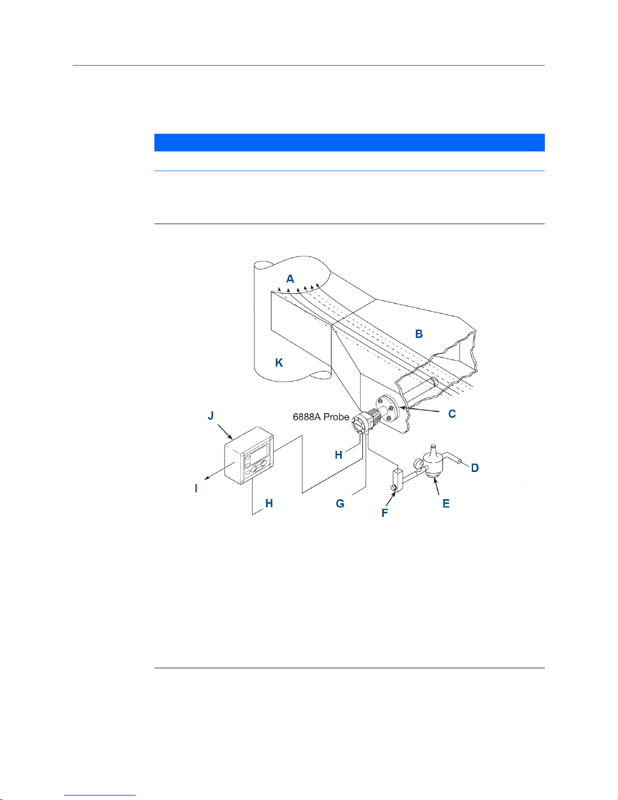
A typical system installation for a Rosemount 6888A with integral electronics is shown in
Figure 2-1.
Typical system installationFigure 2-1:
A. Gases
B. Duct
C. Adapter plate and flange
D. Instrument air supply (reference air)
E. Pressure regulator
F. Flowmeter
G. Calibration gas
H. Line voltage
I. 4 to 20 mA signal
J. Rosemount 6888Xi Advanced Electronics (optional)
K. Stack
A source of instrument air is required at the transmitter for reference air flow [2.0 scfh
(1.0 L/min)]. Since the unit is equipped with an in place calibration feature, you can make
provisions to permanently connect calibration gas bottles to the transmitter.
18 Rosemount 6888A
Page 27

Install
If the calibration gas bottles will be permanently connected, install a check valve next to
the calibration fittings on the probe. This check valve is to prevent breathing of the
calibration gas line and subsequent flue gas condensation and corrosion. The check valve
is in addition to the stop valve on the calibration gas bottles or the solenoid valves in the
Rosemount SPS 40001B or Rosemount IMPS 4000.
If the Rosemount 6888Xi Advanced Electronics option is not used, the 4 to 20 mA signal
from the probe will be loop-powered from the DCS. A 375/475 Field Communicator or
AMS is required to set up and operate the probe.
The optional Rosemount 6888Xi enhanced interface communicates with the probe
transmitter electronics via HART® communications riding on to the 4 to 20 mA signal
coming from the transmitter. If using the 375/475 Field Communicator, connect it to the 4
to 20 mA signal loop between the Rosemount 6888Xi and the control room or data
acquisition system. Connecting the 375/475 Field Communicator between the transmitter
and Rosemount 6888Xi will cause communication errors and affect system operation.
NOTICE
The transmitter electronics is rated Type 4X and IP66 and is capable of operation at
temperatures from -40 to 85 °C (-40 to 185 °F). Retain the packaging in which the Rosemount
6888A arrived from the factory in case any components are to be shipped to another site. This
packaging has been designed to protect the product.
2.2 Mechanical installation
Most combustion processes run only slightly negative or positive in pressure, so that the
probe flange is for mechanical mounting only. The probe is not rated for high pressures. If
this is a new installation, a weld plate for welding to the flue gas duct can be supplied.
WARNING!
ELECTRIC SHOCK
Install all protective equipment covers and safety ground leads after installation. Failure to
install covers and ground leads could result in serious injury or death. The Rosemount 6888A
O2 transmitter can be installed in general purpose areas only. Do not install the transmitter or
the Rosemount 6888Xi in hazardous areas or in the vicinity of flammable liquids.
Reference Manual 19
Page 28
Install
2.2.1 Install probe
Complete the following steps to install the Rosemount 6888A O2 probe.
1. Ensure all components are available to install the Rosemount 6888A O2 probe.
Refer to the probe installation details in Figure 2-1. If using the optional ceramic or
Hastelloy diffusion element, the vee deflector must be correctly oriented.
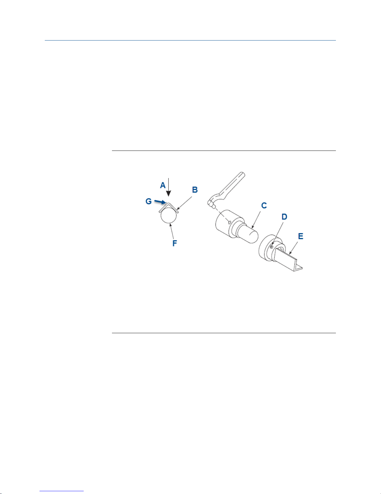
2. Before inserting the Rosemount 6888A probe, check the direction of gas flow in the
duct. Orient the vee deflector so the apex points upstream toward the flow. See
Figure 2-2.
Orienting the Optional Vee DeflectorFigure 2-2:
A. Gas flow direction
B. Vee deflector
C. Diffusion element
D. Setscrew
E. Vee deflector
F. Filter
G. Apex
3. If using the standard square weld plate or an optional flange mounting plate, weld or
bolt the plate onto the duct.
20 Rosemount 6888A
Page 29
Install
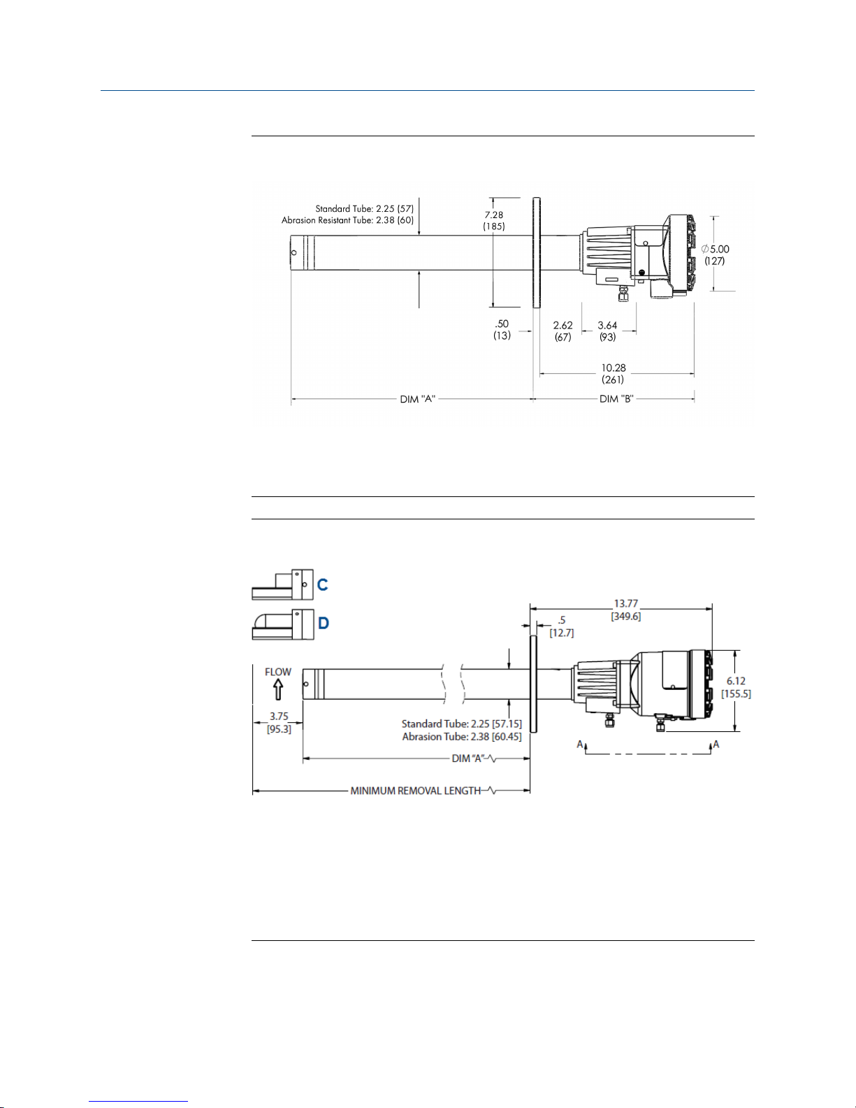
Figure 2-3:
Rosemount 6888A Probe with Standard Terminations/Electronic
Housing
Note
All dimensions are in inches with millimeters in parentheses.
Rosemount 6888A Integral Autocal HousingFigure 2-4:
A. Dimension
B. Dimension
C. Hastelloy diffuser
D. Ceramic diffuser
Note
All dimensions are in inches with millimeters in parentheses.
Reference Manual 21
Page 30
Install
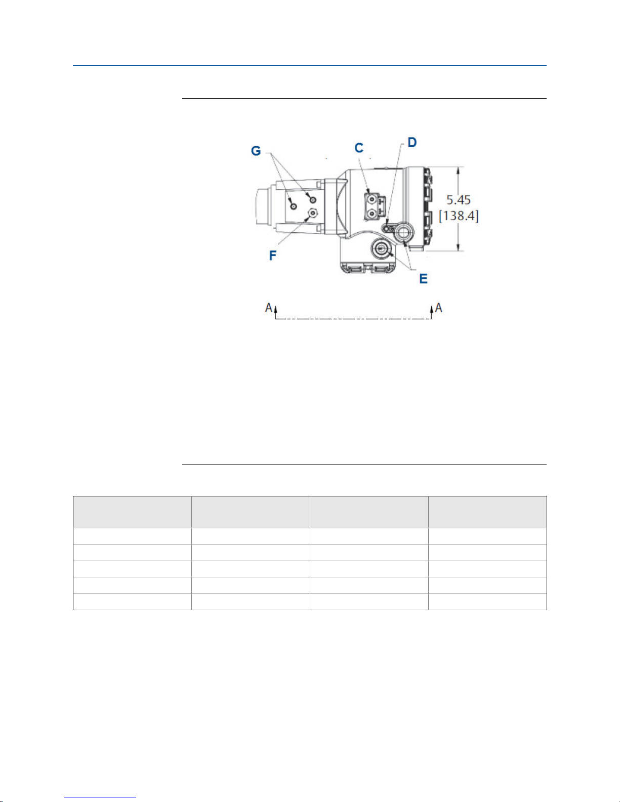
Rosemount 6888A Integral Autocal Housing Close-upFigure 2-5:
A. Dimension
B. Dimension
C. Calibration gas 1/4 tube fittings 5.0 SCFH (2.4 L/min) 20 PSI (138 kPa)
D. #10 socket head cap screw (external ground)
E. 1/2 NPT conduit connection (power, signal)
F. Reference gas 1/4 tube fitting 2.0 SCFH (1.0 L/min) 20 PSI (138 kPa)
G. Reference air vents
Note
All dimensions are in inches with millimeters in parentheses.
Removal/InstallationTable 2-1:
Probe length
457 mm (18 in.) probe 409 mm (16.1in.) 401 mm (15.77 in.) 490 mm (19.26 in.)
0.91 m (3 ft) probe 826 mm (33.52 in.) 1182 mm (46.6 in.) 1271 mm (50.1 in.)
1.83 m (6 ft) probe 1740 mm (68.52 in.) 2097 mm (82.6 in.) 2186 mm (86.1 in.)
2.74 m (9 ft) probe 2655 mm (104.52 in.) 3011 mm (118.6 in.) 3100 mm (122.1 in.)
3.66 m (12 ft) probe 3569 mm (140.52 in.) 3926 mm (154.6 in.) 4015 mm (158.1 in.)
(1) Add 96 mm (3.8 in.) to Dim A and Dim B for probe with ceramic or Hastelloy diffuser.
(1)
Dim A insertion depth
Dim B removal envelope
standard housing
Dim B removal envelope
accessory housing
The through hole diameter in the stack or duct wall and refractory material must be
at least 63.5 mm (2-1/2 in.)
4. Insert probe through the opening in the mounting flange and bolt the unit to the
flange.
22 Rosemount 6888A
Page 31

Probe InstallationFigure 2-6:
A. Dimension
B. Dimension
C. Dimension
D. Four studs, lockwashers, and nuts equally spaced on C dia. B C
Install
Mounting flangeTable 2-2:
ANSI DIN
Flange diameter 7.28 (185)
Hole diameter .75 (20)
(4) holes eq sp on BC 4.75 (121) 5.71 (145)
Installation Weld Plate OutlineTable 2-3:
Dimension ANSI DIN
A
B thread .625 m (11 in.) M16x2
C diameter 4.75 m (121 in.) 5.708 m (145 in.)
6.0 m (152 in.) 7.5 m (191 in.)
Reference Manual 23
Page 32

Install
Drip Loop and Insulation RemovalFigure 2-7:
2.2.2
A. Line voltage
B. Logic I/O, 4-20 mA signal
C. Stack or duct metal wall
D. Adapter plate
E. Insulation
F.
Note
Replace insulation after installing Rosemount 6888A
Variable insertion
The ideal placement of O2 probes is often difficult to determine, and the variable insertion
option is intended to assist in optimizing the ideal probe location.
Variable insertion option
The variable insertion option permits a probe to be slid into and out of a flue gas duct at
infinitely variable depths. This has several advantages over traditional mountings that fix
the probe length with a flange at the time of installation:
• One length of probe can be stocked for any length requirement.
• The flue gas duct where the probe is mounted can be profiled with a single long
probe while the flue gas levels are trended within the control system. This
information can be used to determine the installation sweet spot that is most
representative of a particular burner column (in the case of wall-fired furnaces),
furnace corner (in the case of tangential-fired furnaces), or firing zone (in the case of
a fired process heater).
24 Rosemount 6888A
Page 33

Install
• Process upsets can be diagnosed by again profiling the duct stratification on-line by
sliding probe in and out and recording the O2 levels at different insertion depths.
This provides a good diagnostic for balancing burners and tracking down upset
conditions caused by sticking burner sleeve dampers, roping in coal pipes, classifier
problems, etc.
• A probe can be slid to the most convenient location for a technician to access for the
purposes of conducing a calibration or diagnosing a probe problem.
The variable insertion mount consists of a slip-tube that is mounted to the furnace via a
flange or pipe thread. Slide the O2 probe through this mounting and seal the probe outside
diameter to the slip-tube ID via valve packing material. A stop-collar is provided for safety
to ensure that a probe in a vertical installation does not creep through the packing
material due to gravity after installation. The stop collar has separate holes where screws
can be inserted to jack the probe out of the slip mount if debris builds up on the probe over
time. The packing material can be withdrawn with the probe in situations where the
buildup on the probe is heavy and cannot pass through the packing material.
Installation
An installation permitting variable insertion requires some special considerations:
• Removal envelope: There must be enough room for the probe to slide in and out.
• Utilities: Since the probe will be operating continually as its position is adjusted, the
electrical wires and pneumatic tubing must be able to travel with the probe.
• Duct pressure: Balanced draft and natural draft furnaces typically run at a slightly
negative pressure, so any small leaks in the packing material will draw air into the
furnace. When the probe is removed for service, a flow of fresh air into the furnace
also results. A positive pressure duct, however, releases hot flue gases when the
probe is removed.
• Be mindful that the slip-support holding the end of the probe inside the furnace will
likely be attached to the internal structure that may grow thermally more than the
furnace wall where the probe flange is mounted. A probe that is perfectly aligned
with the slip-support(s) during initial installation (with the furnace off) may be out of
alignment once the furnace heats up.
The variable insertion arrangement is set up for Rosemount 6888A probes with heavy-wall
abrasion-resistant probe bodies only. For probe lengths of 9 feet and longer, an outboard
slip support must be mounted inside the flue gas duct. The support structure may include
angle iron or tube bundles that will be at elevated temperatures during use. Plan for
thermal expansion when installing the outboard slip support.
WARNING!
GAS LEAKS
Some flue gas ducts operate under positive pressure. While the packing material will prevent
most flue gases from escaping into the ambient environment, some leakage can be expected.
Once the probe is fully extracted from the slip-tube, hot flue gases will freely exit the hole in
the slip tube until a replacement probe or core plug is inserted. Observe safety precautions
when removing or inserting a probe into a furnace operating at positive pressure.
Reference Manual 25
Page 34

Install
CAUTION!
This variable insertion mount is intended for use in negative pressure ducts and postive
pressure ducts where the flue gas pressure is no more than 1 psi. Emerson offers other systems
with isolation valve and pressure balancing for applications where the pressure is up to 50 psi.
2.3 Electrical installation
All wiring must conform to local and national codes. Multiple wiring diagrams are shown in
this section. Always refer to the diagrams that apply to your transmitter configuration and
disregard all other wiring diagrams.
WARNING!
ELECTRIC SHOCK
Disconnect and lock out power before connecting the power supply.
Install all protective covers and safety ground leads after installation. Failure to install covers
and ground leads could result in serious injury or death.
2.3.1
To meet the safety requirements of IEC 61010-1 (EC requirement) and ensure safe operation of
this equipment, connect the main electrical power supply through a circuit breaker (min 10 A)
which will disconnect all current-carrying conductors during a fault situation. This circuit
breaker should also include a mechanically operated isolating switch. If not, keep another
external means of disconnecting the supply from the equipment located close by. Circuit
breakers or switches must comply with a recognized standard such as IEC 947.
NOTICE
To maintain proper earth grounding, ensure a positive connection exists between the
transmitter housing and earth. The connecting ground wire must be 14 AWG minimum.
NOTICE
Line voltage, signal, and relay wiring should be rated for at least 105 °C (221 °F).
Wiring for Rosemount 6888 Transmitter probe only (no
Rosemount 6888Xi Electronics)
The Rosemount 6888 transmitter probe has electronics in the blue housing that controls
the heater temperature and also amplifies the raw O2 millivolt signal to a linear 4-20 mA.
The 4-20 mA signal lines can be run directly to the control room and also power the
transmitter electronics. There is no O2 display or keypad on the probe, so you must set up
through HART® communications via a 475 handheld communicator or via Asset
Management Solutions (AMS).
1. Remove the cover from the probe.
2. Connect the line (L1 wire) to the L1 terminal, the netural (L2 wire) to the L2/N
terminal, and the ground wire to the ground lug.
26 Rosemount 6888A
Page 35

The transmitter accepts 120/240 Vac ±10% line voltage and 50/60 Hz. No setup is
required.
Rosemount 6888A Standard Probe HousingFigure 2-8:
Install
3. Connect the 4-20 mA signal wires at the transmitter. Use a shielded twisted wire
pair.
Do not allow bare shield wires to contact the circuit boards. Insulate the shield wires
prior to termination. The transmitter electronics are loop-powered, i.e., the 4-20 mA
signal wires supply 24 Vdc from the DCS or an external power supply.
4. Terminate the shield only at the transmitter electronics housing unless using a
Rosemount 6888Xi. When using the Rosemount 6888Xi Advanced Electronics,
terminate the shield at both ends.
NOTICE
The 4-20 mA signal represents the O2 value and also powers the probe-mounted
electronics. Superimposed on the 4-20 mA signal is HART information accessible
through a Field Communicator or AMS software.
5. Reinstall cover on transmitter.
6. Follow the remaining electrical instructions only if the Rosemount 6888Xi is
included with your system configuration.
Reference Manual 27
Page 36

Install
2.3.2 Standard housing transmitter probe plus Rosemount
6888Xi Electronics
The Rosemount 6888Xi Electronics serve as an operator interface unit with a back-lit
display and keypad. It is capable of two channels, serving two Rosemount 6888 probes.
1. Remove cover screws from the front cover of the Rosemount 6888Xi. Swing down
the front cover of the interface box.
2. Pull out the I/O board on the right side of the card rack inside the Rosemount
6888Xi.
If your system is configured to operate two transmitter probes, there are two I/O
interface boards. See Figure 2-9.
28 Rosemount 6888A
Page 37

Install
Wiring Diagrams - Single/Dual Channel Wiring DiagramFigure 2-9:
Note
A. Except for JP5, JP2, and JP8 on IO board, jumper and switch settings are factory set and are
shown for reference only.
B. IO board 4-20 mA/HART loop power settings:
JP5: Pins 1-2 internal power Rosemount 6888Xi to Rosemount 6888 transmitter, pins 2-3
external power Rosemount 6888Xi to Rosemount 6888 transmitter (requires 2500 resistor
across J4, PR+ to PR-)
JP7/JP8: Pins 1-2 internal power Rosemount 6888Xi to DCS, pins 2-3 external power Rosemount
6888Xi to DCS.
Compare the configuration matrix below to the model number on the probe tag to
confirm the features present in this specific probe.
Remote TypeTable 2-4:
1OXY Single channel O
2OXY Single channel O2 with flame safety interlocking heater
3OXY Dual channel O
2
2
Reference Manual 29
Page 38

Install
Remote Type (continued)Table 2-4:
4OXY Single channel O2 traditional architecture for 120 V probes
30 Rosemount 6888A
Page 39

Install
Rosemount 6888Xi Front and Bottom ViewFigure 2-10:
A. Power supply board
B. Channel #2 IO board
C. Shield ground
D. Channel #1 IO board
E. AC input to P/S
F. Plug
G. Channel #2 alarm relay, SPS/IMPS
H. Channel #2 4-20 mA/HART output
I. Channel #1 alarm relay SPS/IMPS
J. Channel #1 4-20 mA/HART output
Reference Manual 31
Page 40

Install
3. Connect the 4-20 mA signal wires at J4 of the I/O board. Attach the supplied ferrite
clamp over the 4-20 mA out wires that extend past the shield.
NOTICE
Installation of the ferrite clamp over the 4-20 mA out wires is required for the
compliance with the European EMC directive.
4. Terminate the shield of the 4-20 mA signal wires at the designated ground terminal
of the Rosemount 6888Xi. Do not allow bare shield wires to contact the circuit
boards. Insulate the shield wires prior to termination.
5. Connect the signal wires from the Rosemount SPS or Rosemount IMPS (if used) to
the applicable terminals of J3. Refer to the Rosemount SPS 4001B or
Rosemount IMPS 4000 instruction manual for wiring details.
6. Reinstall the I/O board in the card rack of the Rosemount 6888Xi.
7. If your system is configured or two channel operation, repeat steps 2 through 7 to
connect the other probe's signal wires.
8. Remove the probe's connector from the power supply board located on the left side
of the card rack inside the Rosemount 6888Xi.
9. Connect the line, or L1, wire to the L1 terminal and the neutral, or L2, wire to the N
terminal.
10. Reinstall the power supply connector in the power supply board.
2.3.3
Transmitter probe with single-channel Xi and flame
safety interlock
A flame safety interlock by Emerson is available for heater power disconnect whenever
there is a loss of the process flame or a heater runaway condition (heater overtemperature) in the O2 probe. This input is internally powered by the Rosemount 6888Xi
and is actuated via a dry contact output from your flame scanner. A closed contact
indicates a flame is present. An open contact indicates a loss of flame.
Procedure
1. Refer to Figure 2-11. Connect the signal wires from the burner management system
flame status output to the flame status input terminals of J2.
The flame status sensing device is supplied by the customer. Refer to the applicable
OEM documents for signal wiring details.
2. Remove the J1 and J2 connectors from the AC relay board.
3. Connect the AC line input to the J1 connector.
4. Connect the AC power to the probe to the J2 connector.
5. Reinstall connector J1 and J2 to the AC relay board.
32 Rosemount 6888A
Page 41

Install
Single channel with flame safety wiring diagramFigure 2-11:
Note
A. See Rosemount 6888Xi Instruction Manual for additional installation and operating instructions.
B. All wiring marked with an asterisk (*) is factory wiring inside the Rosemount 6888Xi.
C. Except for JP5, JP7, and JP8 on IO board, jumper and switch settings are factory set and are shown
for reference only.
D. IO board 4-20 mA/HART loop power settings
JP5: Pins 1-2 internal power Rosemount 6888Xi to Rosemount 6888 Transmitter, pins 2-3 external
power Rosemount 6888Xi to Rosemount 6888 Transmitter (requires 250 Ω resistor across J4, PR+
to PR-)
JP7/JP8: Pins 1-2 internal power Rosemount 6888Xi to DCS, pins 2-3 external power Rosemount
6888Xi to DCS
See Table 2-4 for the Rosemount 6888Xi configuration matrix.
Reference Manual 33
Page 42

Install
Rosemount 6888Xi Front and Bottom ViewFigure 2-12:
A. Power supply board
B. AC relay board
C. Shield ground
D. IO board
E. Plug
F. AC input
G. Loss of flame output to burner management system
H. Alarm relay, SPS/IMPS
I. 4-20 mA/HART output
34 Rosemount 6888A
Page 43

2.3.4 Transmitter probe with integral autocal and HART
communications
This probe contains gas-switching solenoids so that the Rosemount 6888Xi Electronics can
control the introduction of calibration gases. Calibrations can be initiated via a calibration
recommended diagnostic, time since last calibration, manually via external dry contact,
HART communications, or from the Rosemount 6888Xi local operator interface keypad.
The integral autocal feature can only be implemented when the probe is used with a
Rosemount 6888Xi.
1. Remove the two covers from the transmitter.
2. Connect the line (L1 wire) to the L1 terminal, the neutral (L2) wire to the L2/N
terminal, and the ground wire to the ground lug.
The Rosemount 6888A accepts 120/240 Vac ±10%, 50/60 Hz. No setup is required.
3. Connect the 4-20 mA signal wires form the Rosemount 6888Xi to the connections in
the side chamber of the transmitter.
Do not connect the signal wires to the terminals in the main chamber where the AC
input wires are connected. Use a shielded twisted wire pair. Do not allow bare shield
wires to contact the circuit boards. Insulate the shield wires prior to termination. The
24 Vdc loop power is sourced from the Rosemount 6888Xi.
4. Terminate the shield at both the probe and the Rosemount 6888Xi Advanced
Electronics.
Install
NOTICE
The 4-20 mA signal represents the O2 value and also powers the probe-mounted
electronics. Superimposed on the 4-20 mA signal is HART information accessible
through a field communicator or AMS software.
5. Reinstall both covers on transmitter.
6. Follow the remaining electrical installation instructions for the Rosemount 6888Xi
included with your system configuration.
See Table 2-4 for the Rosemount 6888Xi product matrix.
Reference Manual 35
Page 44

Install
Integral Autocal and HART CommunicationsFigure 2-13:
A. Ferrite clamp
B. Signal
C. Test points
D. #8 pan htd scr (internal ground)
E. Power
F. Test point group
NOTICE
A. Except for JP5, JP7, and JP8 on IO board, jumper and switch settings are factory set and are shown for reference
only.
36 Rosemount 6888A
Page 45

B. IO board: 4-20 mA/HART loop power settings
• JP5
• Pins 1-2: internal power Rosemount 6888 Xi to Rosemount 6888 transmitter
• Pins 2-5: external power Rosemount 6888 Xi to Rosemount 6888 transmitter (requires 2,500 resistor across
J4, PR+ to PR-)
• JP7/JP8
• Pins 1-2: internal power to DCS
• Pins 2-3: external power Rosemount 6888 Xi to DCS
NOTICE
I/O board - Channel 2 is a duplicate of Channel 1.
See Figure 2-10 for the front and bottom view of the Rosemount 6888Xi.
2.3.5 Wire the Rosemount 6888A Transmitter probe with
Install
integral autocal and FOUNDATION™ Fieldbus
communications
This probe contains gas-switching solenoids so that the Rosemount 6888Xi electronics can
control the introduction of calibration gases. Calibrations can be initiated manually via a
calibration recommended diagnostic, time since last calibration, manually via external dry
contact, HART communications, or from the Rosemount 6888Xi local operator interface
keypad. The integral autocal feature can only be implemented when the probe is used with
a Rosemount 6888Xi.
1. Remove the two covers from the transmitter.
2. Connect the line (L1) wire to the L1 terminal, the neutral (L2) wire to the L2/N
terminal, and the ground wire to the ground lug.
The Rosemount 6888A accepts 120/240 Vac ±10% line voltage and 50/60 Hz. No
setup is required.
3. Connect the FOUNDATION Fieldbus wires from the Rosemount 6888 side housing to
the FF segment.
The Rosemount 6888 probe is not rated as intrinsically safe and will render any IS or
FISCO segment it is wired to as non-IS. Use a shielded twisted wire pair. Do not allow
bare shield wires to contact the circuit boards.
4. Terminate the shield at both the probe and the Rosemount 6888Xi advanced
electronics.
NOTICE
The FOUNDATION Fieldbus signal represents the O2 value and also powers the probemounted electronics.
Reference Manual 37
Page 46

Install
5. Reinstall both covers on transmitter.
6. Follow the remaining electrical installation instructions for the Rosemount 6888Xi
included with your system configuration.
2.3.6 Wire the traditional architecture system with direct
replacement probe (no electronics inside)
Here there are no electronics inside the probe head, so the raw sensor signals for the
heater thermocouple and zirconium oxide (O2) sensor are sent to a remote Rosemount
6888Xi electronics. The Rosemount 6888Xi electronics also directly applies power to the
probe heater in order to maintain the correct sensor temperature. This arrangement calls
for a 7-conductor cable to carry this power and the sensor signals. Maximum length for this
cable is 200 feet.
1. Remove cover from probe.
2. Feed all DR probe wiring through line power conduit of probe.
3. Connect DR probe heater power leads to DR probe connectors, Figure 2-14.
See Table 2-4 for the Rosemount 6888Xi product matrix.
38 Rosemount 6888A
Page 47

Install
Figure 2-14:
Wiring Diagrams - Traditional Architecture with Direct
Replacement Probe (no Electronics Inside)
Note
A. See Rosemount 6888Xi Instruction Manual for additional installation and operating
instructions.
B. All wiring marked with an asterisk (*) is factory wiring inside the Rosemount 6888Xi.
C. Except for JP7 and JP8 on IO board, jumper and switch settings are factory set and are shown
for reference only.
Reference Manual 39
Page 48

Install
2.3.7
A. Power supply board
B. DR board
C. Shield ground
D. IO board
E. Plug
F. Probe cable
G. AC input
H. Alarm relay SPS/IMPS
I. 4-20 mA/HART output
4. Connect O2 signal and thermocouple wires to DR probe connectors.
Wire the traditional architecture cable connections
A traditional architecture configuration is used to provide for remote location of the
transmitter electronics. All electronics are housed inside the Rosemount 6888Xi. A multiconductor power/signal cable connects between the probe and the Rosemount 6888Xi.
Use the following procedure to connect the traditional architecture probe to the
Rosemount 6888Xi.
40 Rosemount 6888A
Page 49

NOTICE
The traditional architecture cable is provided at the specified length and is ready for
installation. The cable glands must be properly terminated to maintain EMC/EMI noise
protection.
Procedure
1. Run the 7-conductor cable between the traditional architecture probe and the
installation site for the Rosemount 6888Xi. Use new cable conduit or trough as
needed.
2. Install the cable and lead wires to the probe per manufacturer's instructions.
3. Install the cable at the probe housing and at the Rosemount 6888Xi enclosure
according to the following procedure:
a. Unscrew the locking nut from the gland assembly and slide the locking nut back
along the cable.
b. Pull the gland body away from the plastic insert.
Use care not to damage the cable shield braid.
c. Insert the cable wires into the proper entry port in either the probe housing or
the Rosemount 6888Xi enclosure.
d. At the probe housing, apply Teflon® tape or similar sealing compound to the
tapered pipe threads. Thread the gland body into the probe housing until
properly seated.
e. At the Rosemount 6888Xi enclosure, insert the gland body into the left front
cable port from the inside of the enclosure. Use the rubber O-ring provided to
seal the cable port.
f. Ensure the cable shield braid is evenly formed over the gray insert.
Install
When properly formed, the braid should be evenly spaced around the
circumference of the insert and not extend beyond the narrow diameter portion.
g. Carefully press the gray insert into the gland body. The grooves on the insert
should align with similar grooves inside the gland body. Press the insert in until it
bottoms out in the gland body.
h. Slide the locking nut up and thread it onto the gland body. Tighten the locking
nut so the rubber grommet inside the plastic insert compresses against the cable
wall to provide an environmental seal.
4. At the Rosemount 6888Xi, connect the cable leads to the connectors on the
transmitter I/O board.
Reference Manual 41
Page 50

Install
2.4 Pneumatic installation
2.4.1 Reference air package
After the Rosemount 6888A is installed, connect the reference air set to the Rosemount
6888A unit.
Refer to the schematic diagram in Figure 2-15 for a locally assembled reference air supply.
Instrument air (reference air): 5 psi (34 kPa) minimum, 8 psi (54 kPa) maximum at 2.0 scfh
(1.01 L/min) maximum; less than 40 parts per million total hydrocarbons. Regulator outlet
pressure should be set at 5 psi (34 kPa). Reference air can be supplied by the reference air
set or the optional Rosemount SPS 4001B or Rosemount IMPS 4000.
Plant Schematic Diagram, Standard HousingFigure 2-15:
A. Vent
B. Calibration gas: 1/4 in. tube
C. Reference air flowmeter
D. 0.25-18 NPT female inlet connection
E. 0.25 or 6 mm O.D. tubing (supplied by customer)
F. Reference gas: 1/4 in. tube
42 Rosemount 6888A
Page 51

Plant Air Schematic Diagram, Accessory HousingFigure 2-16:
A. Vent
B. Calibration gas 1: 1/4 in. tube
C. Calibration gas 2: 1/4 in. tube
D. Reference air flowmeter
E. 0.25-18 NPT female inlet connection
F. 0.25 or 6 mm O.D. tubing (supplied by customer)
G. Reference gas: 1/4 in. tube
Install
Reference Manual 43
Page 52

Install
Manual Calibration PanelFigure 2-17:
Note
Dimensions are in inches with millimeters in parentheses.
Reference air components are included in the optional manual calibration panel
(Figure 2-17), the Rosemount SPS 4001 Single Probe Autocalibration Sequencer, and the
Rosemount IMPS 4000 Intelligent Multiprobe Test Gas Sequencer.
44 Rosemount 6888A
Page 53

NOTICE
The optional Rosemount SPS 4001B or Rosemount IMPS 4000 Sequencer can only be used
when the Rosemount 6888Xi advanced electronics option is selected. The Rosemount 6888Xi
must be properly configured for autocalibration. See Chapter 3.
See the SPS 4001B Single Probe Autocalibration Sequencer Instruction Manual or the
IMPS 4000 Intelligent Multiprobe Test Gas Sequencer Instruction Manual for wiring and
pneumatic connections.
2.4.2 Calibration gas
Two calibration gas concentrations are used with this transmitter, low gas - 0.4% O2,
balance N2, and high gas - 8% O2, balance N2.
CAUTION!
CALIBRATION READING ERRORS
Do not use 100% nitrogen as a low gas (zero gas). Emerson suggests that gas for the low (zero)
be between 0.4% and 2.0% O2. Do not use gases with hydrocarbon concentrations of more than
40 parts per million. Failure to use proper gases will result in erroneous readings.
Install
CAUTION!
EQUIPMENT DAMAGE
If the ducts will be washed down during outage, MAKE SURE to power down the Rosemount
6888A units and remove them from the wash areas.
NOTICE
Upon completing installation, make sure that the transmitter is turned on and operating prior
to firing up the combustion process. Damage can result from having a cold unit exposed to the
process gases. During outages, if possible, leave all units running to prevent condensation and
premature aging from thermal cycling.
An optional manual calibration panel is shown in Figure 2-17. See Figure 2-18 for the
Rosemount 6888A probe calibration gas connection ports.
Reference Manual 45
Page 54

Install
Rosemount 6888A Calibration Gas ConnectionsFigure 2-18:
A. Cal gas in
B. Ref air vent
C. Ref air in
Traditional Architecture Cable Gland AssemblyFigure 2-19:
46 Rosemount 6888A
Page 55

Configuration, startup, and operation
3 Configuration, startup, and operation
WARNING!
ELECTRIC SHOCK
Install all protective equipment covers and safety ground leads before equipment startup.
Failure to install covers and ground leads could result in serious injury or death.
CAUTION!
EQUIPMENT DAMAGE
If external loop power is used, the power supply must be a safety extra low voltage (SELV)
type.
3.1 Power up Rosemount 6888 Transmitter
without Rosemount 6888Xi
Complete the following steps to apply power to the Rosemount 6888 Transmitter without
connecting it to the Rosemount 6888Xi.
1. Apply AC line power to the transmitter.
2. Apply 24 Vdc loop power to the transmitter.
3. Using either the DCS control or a Field Communicator, verify communications to the
transmitter.
The transmitter probe takes approximately 45 minutes to warm up to the 736 °C
(1357 °F) heater setpoint. The 4-20 mA signal remains at a default value of 3.5 mA,
and the O2 reading remains at 0% through this warm-up period. After warm-up, the
probe begins reading oxygen, and the 4-20 mA output is based on the default range
of 0-10% O2.
If there is an error condition at startup, an alarm message is displayed.
Reference Manual 47
Page 56

Configuration, startup, and operation
3.2 Power up the Rosemount 6888 Transmitter
with single/dual channel or single channel and
flame safety interlock Rosemount 6888Xi
Complete the following steps to power up the Rosemount 6888 Transmitter with single/
dual channel or single channel and flame safety interlock Rosemount 6888Xi.
1. Appy AC line power to the transmitter.
2. Apply AC line power to the Rosemount 6888Xi. Run the Rosemount 6888Xi Quick
Start Wizard (Section 3.4). At the Auto Cal Device screen, select the calibration
method based on the Rosemount 6888 Transmitter as follows:
a. Standard probe housing configuration - Select None, SPS, or IMPS as appropriate.
Do not select Integral or calibration will not be possible.
b. Integral autocal probe housing - Select Integral only. If Integral is not selected,
calibration will not be possible.
3. Verify communications between the transmitter and the Rosemount 6888Xi.
The Rosemount 6888Xi display is preconfigured to display O2 and cell temperature
for single channel configurations and both O2 readings for dual channel
configurations.
3.3
The transmitter probe takes approximately 45 minutes to warm up to the 736 °C (1357 °F)
heater setpoint. The 4-20 mA signal remains at a default value of 3.5 mA, and the O
reading remains at 0% through this warm-up period. After warm up, the probe begins
reading oxygen, and the 4-20 mA output is based on the default range of 0-10% O2.
If there is an error condition at startup, an alarm message is displayed on the Rosemount
6888Xi.
2
Power up the Rosemount 6888 direct
replacement probe (no electronics inside) with
traditional architecture Rosemount 6888Xi
Complete the following steps to power up the Rosemount 6888 direct replacement probe
with the Rosemount 6888Xi Electronics.
1. Apply AC line power to the Rosemount 6888Xi.
2. Run the Quick Start Wizard as described in Section 3.4.
3. At the Auto Cal Device screen, select None, SPS, or IMPS as appropriate.
Do not select Integral or calibration will not be possible.
The transmitter probe takes approximately 45 minutes to warm up to the 736 °C (1357 °F)
heater setpoint. The 4-20 mA signal remains at a default value of 3.5 mA, and the O
reading remains at 0% through this warm-up period. After warm up, the probe begins
reading oxygen, and the 4-20 mA output is based on the default range of 0-10% O2.
2
48 Rosemount 6888A
Page 57

Configuration, startup, and operation
If there is an error condition at startup, an alarm message is displayed on the Rosemount
6888Xi.
3.4 Rosemount 6888Xi Quick Start Wizard
When the Rosemount 6888Xi is first powered, a short wizard program guides you through
the basic setup. Once configured, the Rosemount 6888Xi retains the setup, and the wizard
will not repeat.
1. Apply power to the Rosemount 6888Xi.
Once boot-up is complete, the Quick Start Wizard screen appears. With a dual
channel Rosemount 6888Xi, the wizard runs for both channels in succession.
2. Press Enter to continue.
3. At the Sensor Type screen, use the Up and Down keys to select O2.
Do not select CO as this option is reserved for future use.
4. Press Enter to continue.
5. At the Device Type screen use the Up and Down keys to select HART® or FF
(FOUNDATION™ Fieldbus), whichever applies.
6. At the Auto Cal Device screen, use the Up and Down keys to select the calibration
method to be used. The methods are defined as follows:
• None - Manual calibration with the standard probe housing configuration
• SPS - Automatic calibration with the standard probe housing configuration using
the Rosemount SPS 4001B
• IMPS - Automatic calibration with the standard probe housing configuration
using the Rosemount IMPS
• Integral - Automatic calibration with the integral autocal probe housing
configuration
7. Press Enter to continue.
NOTICE
If SPS, IMPS, or Integral is selected, you must still configure automatic calibration as On.
Other parameters, such as test gas values and gas times, should be verified as well. Refer
to the Rosemount 6888Xi Reference Manual for calibration setup details.
8. When prompted by Setup Correct?, use the Up and Down keys to select Yes.
If you select No, the wizard restarts.
9. Press Enter to continue.
The Rosemount 6888Xi displays several screens while saving the configuration, resets
itself, and then returns to the main screen.
Reference Manual 49
Page 58

Configuration, startup, and operation
3.5 Re-initiating Rosemount 6888Xi wizard
To re-initiate the wizard setup, you must reset the I/O board to default factory conditions.
1. Apply power to the Rosemount 6888Xi.
2. When the main screen appears, press Menu several times until the System menu
appears. Use the Up and Down keys to select Configure IOB. Press Enter to continue.
3. When the Configure IOB screen appears, use the Up and Down keys to select I/O
Board 1. With a dual channel Rosemount 6888Xi, you can reset and reconfigure
either or both I/O boards. Press Enter to continue.
4. When the I/O board 1 menu appears, use the Up and Down keys to select Reset I/O
Board. Press Enter to continue.
5. When the Reset menu appears, use the Up and Down keys to select Factory Defaults.
Press Enter to continue.
6. When prompted, use the Up and Down keys to select Yes. Press Enter to continue.
The Rosemount 6888Xi displays several screens while saving the configuration, resets
itself, and then displays the Wizard screen.
3.6 Calibration
The Rosemount 6888 O
without removing the instrument from the process duct and also while the combustion
process is on-line. A stainless steel tube runs the length of the probe and delivers the
calibration gases into the cell area. Factory calibration is usually satisfactory for initial
startup and operation, but the most accurate measurement is gained by executing a
calibration under normal operating conditions.
Emerson recommends using 0.4% O2 and 8% O2 as calibration gases, with a balance of
nitrogen in the gas bottles, but other values can be used as long as the electronics are
configured identically. Do not use instrument air or pure nitrogen as calibration gas values.
Use a two-stage pressure regulator to establish a pressure of 20 psi from the bottles and
set the flowmeter to 5 scfh flow rate.
3.6.1
Manual/semi-automatic calibration
The Rosemount 6888 probe with the standard housing can be calibrated in a semiautomatic fashion with a technician following prompts via the display of the Rosemount
6888Xi Electronics or via HART communications to a Field Communicator or AMS console.
The technician needs to manually switch the gases based upon these prompts. Emerson
recommends using 0.4% O2 and 8% O2, balance nitrogen as calibration gases. Always use a
two-stage pressure regulator set to 20 psi. Set the calibration gas flowmeter for a
maximum of 5 scfh with the cal gas fitting removed from the probe. A diffuser/filter that is
plugged over time may cause the flowmeter to deliver less flow to the sensing cell, but
never readjust the flow rate until a new diffuser is installed. Readjusting the flowmeter
back up to the 5 scfh level could pressurize the cell during calibration and cause the O
reading to shift downwards.
analyzer system can be calibrated in the installed condition
2
2
50 Rosemount 6888A
Page 59

The electronics determine if the calibration was successful and calculate new calibration
values. New calibration values are not automatically loaded into the electronics after a
successful calibration, however. The technician has the opportunity to accept or reject the
new values. (A significant calibration change may cause a bump in the O2 readings at the
DCS console, causing operator concern). Record the calibration data on a log (cell slope,
constant, and impedance, as well as the speed of response data). If the electronics is used,
it stores calibration data for the past 10 successful calibrations.
CAUTION!
READING ERRORS
Make sure the calibration gas cap is replaced tightly after calibration is complete. A loose or
missing cap can permit fresh air to bias the O2 readings high in processes that run at negative
pressure.
3.6.2 Fully automatic calibration
For fully automatic calibration, the Rosemount 6888Xi Electronics must manage the
actuation of solenoids to introduce gases into the probe.
Configuration, startup, and operation
Rosemount 6888 probes with standard electronics housing
In addition to the Rosemount 6888Xi, this arrangement requires a separate single probe
sequencer (SPS), which is a solenoid box for switching calibration gases, or a larger
intelligent multiprobe sequencer (IMPS), which can handle the autocal for up to four
probes in one box.
The automatic calibration can be initiated in several ways:
• Via a calibration recommended diagnostic that is periodically checking cell
impedance
• Via push button on the Rosemount 6888Xi electronics
• Via HART communications from a 475 handheld communicator or AMS
• Via an external contact closure
• Via time since the last successful calibration
If the O2 measurement is being used for automatic control, always place the O2 control
loop into manual prior to calibrating. Always inform the operator prior to calibrating. The
Rosemount 6888Xi Electronics provides an in cal contact closure for this purpose. An
initiate cal contact is also provided.
The Rosemount 6888Xi Electronics sequences the calibration gases in turn into the sensing
cell.A 300 second flow time is the factory default for both gases and also for the purge
cycle, which lets the probe signal come back to the normal flue gas readings. The 4-20 mA
signal representing O2 can be held during the calibration cycle or permitted to vary with
the bottled gases, in which case a record of the calibration can be trended at the DCS.
Calibration setup is found under the detailed setup menu.
Reference Manual 51
Page 60

Configuration, startup, and operation
Rosemount 6888 probe with integral autocal housing
This probe contains the autocal solenoids within the blue electronics housing, eliminating
the need and cost for an SPS or IMPS solenoid enclosure. Both calibration gases are
permanently piped into two ports on the probe. It's important to confirm that there are no
piping leaks or the calibration bottles will leak down prematurely.
Note
The calibration sequence from the Rosemount 6888Xi electronics will be identical to that for
manual/semiautomatic calibration, but with the integral auto cal version of this probe it is not
possible to conduct a manual calibration. The factory offers a probe rebuild capacity if solenoid or
other failures occur.
Note
Calibration gas bottles are piped and under pressure at all times, so be sure to leak-check all fittings,
tubings, and connections. Always use dual-stage pressure regulators.
3.6.3 Other features associated with calibration
1. Cal check capability: You can choose to look at new calibration values prior to having
them load in and become active. If this feature is selected, a calibration
changed alarm comes up after the calibration is complete. Push the Diagnostics
button on the Rosemount 6888Xi to require an Accept Cal step so that the
technician or operator can decide if they are ready to accept a potentially large
change in calibration values.
2. Plugged diffuser diagnostic: This feature measures the return-to-process rate after
calibration gases are removed and will alarm when this tiem exceeds 75% of the
purge time configured. A purge time too short alarm indicates that the
diagnostic could not work because of a short purge time and is another indication
that the diffuser is plugged. Increase purge time in this case.
Another feature that comes with the plugged diffuser diagnostic is auto gas
switching. This feature switches cal gases and also ends the purge sequence when
the readings settle out, vs. waiting for a configured flow time. This saves time and
gas.
3. Tolerance check: Alarms if the cell MV signal is significantly different from the
expected signal of the bottles noted in the setup. This indicates if the wrong bottles
are being used or if a bottle runs out in the middle of a calibration.
Calibration setup is under the Detailed Setup menu.
Calibration setup can be found in the Rosemount 6888Xi menu.
For the factory default menu, see Figure 3-1.
52 Rosemount 6888A
Page 61

Configuration, startup, and operation
Calibration DefaultsFigure 3-1:
Reference Manual 53
Page 62

Configuration, startup, and operation
HART Menu Trees - Rosemount 6888XiFigure 3-2:
54 Rosemount 6888A
Page 63

Configuration, startup, and operation
Reference Manual 55
Page 64

Configuration, startup, and operation
56 Rosemount 6888A
Page 65

Configuration, startup, and operation
Reference Manual 57
Page 66

Configuration, startup, and operation
58 Rosemount 6888A
Page 67

Configuration, startup, and operation
Reference Manual 59
Page 68

Configuration, startup, and operation
60 Rosemount 6888A
Page 69

Configuration, startup, and operation
HART Menu Trees - 375/475 Field CommunicatorFigure 3-3:
Reference Manual 61
Page 70

Configuration, startup, and operation
62 Rosemount 6888A
Page 71

Configuration, startup, and operation
Reference Manual 63
Page 72

Configuration, startup, and operation
64 Rosemount 6888A
Page 73

Configuration, startup, and operation
FOUNDATION Fieldbus Menu Trees - Rosemount 6888XiFigure 3-4:
Reference Manual 65
Page 74

Configuration, startup, and operation
66 Rosemount 6888A
Page 75

Configuration, startup, and operation
Reference Manual 67
Page 76

Configuration, startup, and operation
68 Rosemount 6888A
Page 77

Configuration, startup, and operation
Reference Manual 69
Page 78

Configuration, startup, and operation
FOUNDATION Fieldbus Menu Trees - 375/475 Field CommunicatorFigure 3-5:
70 Rosemount 6888A
Page 79

Configuration, startup, and operation
Reference Manual 71
Page 80

Configuration, startup, and operation
72 Rosemount 6888A
Page 81

Configuration, startup, and operation
Reference Manual 73
Page 82

Configuration, startup, and operation
74 Rosemount 6888A
Page 83

Configuration, startup, and operation
3.7 Startup
The transmitter begins operation when the signal wiring is connected and heater power is
supplied to the transmitter. First power the AC line voltage to the heater and then power
the 24 Vdc power/signal loop for the transmitter electronics.
The O2 probe takes approximately 45 minutes to warm up to the 736 °C (1357 °F) heater
setpoint. The 4-20 mA signal remains at a default value of 3.5 mA through this warmup
period. Once warm, the O2 reads oxygen, and the 4-20 mA signal's reading is based on the
default range of 0-10% O2.
3.7.1
Error conditions
If there is an error condition at startup, an alarm message is displayed. Refer to Chapter 4 to
determine the cause of the error. Clear the error and cycle power. The %O2 and
temperature display should return without the alarm message.
Reference Manual 75
Page 84

Configuration, startup, and operation
3.8 System parameter descriptions
Among the parameters available through the 375/475 Communicator menus are a
number of system parameters. The system parameters define variables that configure a
specific probe in the transmitter system. System parameters are described in the following
table.
System ParametersTable 3-1:
Parameter name Unit Description
O
2
O2 Temp °C Current O2 sensor temperature.
CJC Temp °C Current cold junction temperature.
O2 Cell mV Raw mV value for O2 sensor.
Cell Imp ohm Cell impedance/sensor resistance measured.
Heater V Heater voltage.
O2AO mA Analog output value represents the O2 concentration
O2 Temp Max °C This is the highest O2 sensor temperature reached since
O2 Temp Max Time Days ago Time stamp of the highest O2 sensor temperature reached
Temperature | CJC Max °C This is the highest temperature reached at the cold junc-
Temperature | CJC Max Time Days ago Time stamp of the highest temperature reached at the
Voltage | Heater Max °C This is the highest heater voltage reached since last reset.
Voltage | Heater Max Time Days ago Time stamp of the highest heater voltage reached since
Voltage | Cell Max °C This is the highest cell voltage reached since last reset.
Voltage | Cell Max Time Days ago Time stamp of the highest cell voltage reached since last
OP Mode -- Device operating mode:
Active alarms -- Current alarms (see Chapter 4)
% Current oxygen concentration value (O2 %). The value
should reflect the last good O2 value if it is in the Lock state
during calibration.
measurement.
last reset.
since last reset.
tion since last reset.
cold junction since last reset.
last reset.
reset.
PO = Power up
WU = Warm up (analog output is railed)
NM = Normal operation
CA = Calibrating (analog output can be tracking or locked
at last good value based on AO Tracks configuration)
AL = Alarm detected (recoverable)
SF = Alarm detected (non-recoverable)
76 Rosemount 6888A
Page 85

System Parameters (continued)Table 3-1:
Parameter name Unit Description
Device -- Alarm state
Failed -- Alarm state: On/Off
NV Memory Fail, Board Temp High, Factory
Mode, Heater Ramp Rate
Maintenance 1 -- Alarm state: On/Off
O2 Sensor Open, O2 T/C Open, O2 Temp Low, O2 Temp
High, O2 T/C Shorted, O2 T/C Reversed, Heater Fail-
ure, Burner Flameout
Maintenance 2 -- Alarm state: On/Off
Xmtr Disconnect, Cal Recommended, Cal
Failed, Cell Imp High, Probe Mismatch
Advisory -- Alarm state:
Xmtr Disconnect, Cal Recommended, Cal
Failed, Cell Imp High, Probe Mismatch
Configuration, startup, and operation
Duty Cycle -- O2 heater duty cycle. Value between 0 and 1.
O2 Temp SP °C PID temperature set point.
Heater Ramp Rate °C/sec Heater ramp rate calculated in °C per second.
Operating Status -- Device configuration: On/Off
Factory Mode, Flame Status (IO Board DIP Switch
setting), Auto Cal Device, Relay 1 Device, Re-
lay 2 Device, AO Device
Xmtr EE Val -- Transmitter board nonvolatile memory diagnostic.
Xmtr Restart -- Software restart count for the transmitter.
HART | Device Rev -- HART device revision number.
Transmitter | Version -- Software version number for the transmitter.
Tag -- Device tag: Up to 8 characters long.
Serial Number -- Probe serial number.
Device ID -- Unique device ID number. (HART)
PV -- Primary variable assignment: O2 (HART).
SV -- Secondary variable assignment: Cell imp (HART).
TV -- Third variable assignment: Cell imp (HART).
4V -- Fourth variable assignment: O2 cell (HART).
Xmtr Address -- Transmitter board polling address.
O2 LRV % Primary variable (O2%) lower range value.
O2 URV % Primary variable (O2%) upper range value.
Reference Manual 77
Page 86

Configuration, startup, and operation
System Parameters (continued)Table 3-1:
Parameter name Unit Description
Alarm Level -- O2 alarm level
0 = 3.5 mA
1 = 21.1 mA
Cal Gas 1 % Test gas 1 value. This is the actual value of the gas being
applied during the Test Gas 1 phase of a calibration.
Cal Gas 2 % Test gas 2 value. This is the actual value of the gas being
applied during the Test Gas 2 phase of a calibration.
Gas Time sec Test gas application time. This is the length of time test
gases are applied to the O2 probe during low or high test
gas phase of a calibration.
Purge Time sec Test gas purge time. This is the length of time before the
output will be returned to the process reading after a calibration.
Slope mV/Dec Current calibration slope. This is the slope value that was
calculated as a result of the last successful calibration.
Constant mV Current calibration constant. This is the constant value
that was calculated as a result of the last successful calibration.
Impedance ohm Cell impedance. This is the sensor resistance that was cal-
culated as a result of the last successful calibration.
Time Days ago Time stamp of the last successful calibration.
Cal Logs | Slope mV/Dec Previous calibration slope. There are ten calibration results.
1 is the most recent, and 10 is the least recent calibration
slope.
Cal Logs | Constant mV Previous calibration constant. There are ten calibration re-
sults. 1 is the most recent, and 10 is the least recent calibration constant.
Cal Logs | Impedance ohm Previous cell impedance. This is the sensor resistance that
was calculated as a result of a previous successful calibration. There are ten calibration results. Index 1 is the
most recent, and Index 10 is the least recent sensor resistance measured.
Cal Logs | Time Days ago Time stamp of the previous successful calibration. There
are ten calibration time stamps. Index 1 is the most recent, and Index 10 is the least recent time stamp.
78 Rosemount 6888A
Page 87

System Parameters (continued)Table 3-1:
Parameter name Unit Description
Cal Result -- Calibration result:
0 = None
1 = Success
2 = Failed constant
3 = Failed slope
4 = Failed temperature
5 = Gas 1 tolerance error
6 = Gas 2 tolerance error
7-10 (future)
11 = AutoCal no resp
12 = AutoCal out of sync
13 = AutoCal abort
14 = No solenoid
15 = Warmup abort
16 = Alarm abort
Configuration, startup, and operation
3.9 Parameter setup
3.9.1 Test gas values
Use a Field Communicator to set test gas values for calibration. A Rosemount 6888A
shipped from the factory has test gas values for low and high set to 0.4% and 8.0%
respectively. Perform this same process any time a transmitter board is replaced.
1. Use the 375/475 Field Communicator to access the main HART menu.
2. From the main menu, select CONFIGURE.
3. From the CONFIGURE menu, select MANUAL SETUP.
4. From the MANUAL SETUP menu, select CALIBRATION.
5. From the CALIBRATION menu, select GAS 1.
6. Press the Right key to edit the gas value.
7. Use the stylus to enter the new gas value. Then press ENTER when finished.
8. Use the stylus to select SEND to update the Rosemount 6888A.
9. Repeat steps 5 through 8 for Gas 2.
3.9.2
Set test gas times
Use a Field Communicator to set test gas flow time and purge time for calibration.
Reference Manual 79
Page 88

Configuration, startup, and operation
A Rosemount 6888A shipped from the factory has test gas flow time and purge time set to
300 seconds. You must complete the same process any time a transmitter board is
replaced.
Procedure
1. Use the 375/475 Field Communicator to access the main HART menu.
2. From the main menu, select CONFIGURE.
3. From the CONFIGURE menu, select MANUAL SETUP.
4. From the MANUAL SETUP menu, select CALIBRATION.
5. From the CALIBRATION menu, select GAS TIME.
6. Press the Right key to edit the gas value.
7. Use the stylus to enter the new gas value; then press ENTER when finished.
8. Use the stylus to select SEND to update the Rosemount 6888A.
9. From the GAS TIME menu, select PURGE TIME.
10. Press the Right key to edit the gas value.
11. Use the stylus to enter the new gas value; then press ENTER when finished.
12. Use the stylus to select SEND to update the Rosemount 6888A.
3.9.3 Track output during calibration
Use a Field Communicator to set how the analog output value will function during
calibration.
A Rosemount 6888A shipped from the factory has output tracking set to No, i.e., the
analog output holds the last value during the calibration cycle. You must perform this
same process any time a transmitter board is replaced.
Procedure
1. Use the 375/475 Field Communicator to access the main HART menu.
2. From the main menu, select CONFIGURE.
3. From the CONFIGURE menu, select MANUAL SETUP.
4. From the MANUAL SETUP menu, select CALIBRATION.
5. From the CALIBRATION menu, select ANALOG OUTPUT TRACK.
6. Press the Right key to edit, then the Up and Down keys to select YES or NO.
• No - The analog output holds the last value during calibration.
• Yes - The analog output tracks the actual measurement during calibration.
7. Use the stylus to press ENTER when finished.
8. Use the stylus to select SEND to update the Rosemount 6888A.
80 Rosemount 6888A
Page 89

3.9.4 Configure analog output
The analog output signal from the Rosemount 6888A can be configured for the 4-20 mA
range and fault condition. A separate configuration is set up when the Rosemount 6888A
is used with the optional Rosemount 6888Xi Advanced Electronics. When the Rosemount
6888A is used without the Rosemount 6888Xi, this parameter must be set to NO. If it is set
to YES and a Rosemount 6888Xi is not connected, the Rosemount 6888A triggers an alarm
and forces the analog output to the fault level. If the Rosemount 6888A is used later with a
Rosemount 6888Xi, the Rosemount 6888Xi automatically sets this parameter to YES.
An Rosemount 6888A shipped from the output has the analog outputs set to 4 to 20 mA
range with a 3.5 mA alarm level. You must complete the same process any time
transmitter board is replaced.
1. Use the 375/475 Field Communicator to access the main HART menu.
2. From the main menu, select CONFIGURE.
3. From the CONFIGURE menu, select MANUAL SETUP.
4. From the MANUAL SETUP menu, select ANALOG OUTPUT.
5. From the ANALOG OUTPUT menu, select from the following parameters; then press
ENTER.
• O2 LRV: O2 value at lower analog output value (0% at 4 mA, non-configurable)
• O2 URV: O2 value at upper analog output value (50% max at 20 mA)
• Output Range: Range of analog output (4-20 mA, non-configurable)
• Alarm level: O2 alarm level (3.5 mA or 21.1 mA)
• Xi Mode: Selects whether or not the Rosemount 6888A is used with a Rosemount
6888Xi (should always be set to NO for a stand-alone Rosemount 6888A)
Configuration, startup, and operation
3.10
6. Use the stylus to enter the value; then press ENTER when finished.
7. Use the stylus to select SEND to update the Rosemount 6888A.
Calibrate
New O
cells may require calibration every few weeks as they near the end of their life.
A CALIBRATION RECOMMENDED alarm provides notice of when a calibration is required.
This strategy ensures that the O2 reading is always accurate and eliminates many
unnecessary calibrations based on calendar days or weeks since previous calibration.
You can calibrate the Rosemount 6888A transmitter manually through the handheld
375/475 Field Communicator or the optional Rosemount 6888Xi. Fully automatic
calibration can be performed using the optional Rosemount 6888Xi advanced electronics
and the Rosemount SPS4001B Single Probe Autocalibration Sequencer or the Rosemount
IMPS 4000 Intelligent Multiprobe Sequencer.
cells may operate for more than a year without requiring calibration, but older
2
Reference Manual 81
Page 90

Configuration, startup, and operation
3.10.1 Calibration procedure
This section covers manual calibration. For automatic calibration details, see the
instruction manual for the Rosemount SPS 4001B Single Probe Autocalibration Sequencer
or the Rosemount IMPS 4000 Intelligent Multiprobe Test Gas Sequencer.
1. Use the 375/475 Field Communicator to access the main HART menu.
2. From the main menu, select CONFIGURE.
3. From the CONFIGURE menu, select CALIBRATION.
4. From the CALIBRATION menu, again select CALIBRATION.
5. From the CALIBRATION menu, select O2 CALIBRATION.
WARNING!
Failure to remove the Rosemount 6888A from automatic control loops prior to
performing this procedure may result in a dangerous operating condition.
Calibration Method - SimplifiedFigure 3-6:
6. In the first screen, a Loop should be removed from automatic control
warning occurs. Remove the Rosemount 6888A from any automatic loop controls to
avoid a potentially dangerous operating condition. Press OK when ready.
7. At the next screen, when the step shows APPLY GAS 1, press OK to continue.
8. When Flow Gas 1 and Read Gas 1 are complete and the step shows APPLY GAS 2,
press OK to continue.
9. When Flow Gas 2 and Read Gas 2 are complete and the step shows STOP GAS,
press OK to continue the calibration with purge.
10. When the screen shows Loop may be returned to automatic control,
press OK to return to the CALIBRATION screen.
11. At the CALIBRATION menu, select RESULT.
At the RESULT menu, the results of the calibration are displayed. In the event the
calibration cycle fails, the reason is displayed here as well. The calibration results are
described as follows:
82 Rosemount 6888A
Page 91

Configuration, startup, and operation
• Success: Calibration completed successfully.
• Failed Constant: The calculated calibration constant is outside the range of
±20.00.
• Failed Slope: The calculated calibration slope is outside the range of 34.5 to 57.5.
• WarmUp Abort: Attempted to perform a calibration during warmup.
• Alarm Abort: Another alarm occurred and caused the calibration cycle to abort.
12. In the event of a calibration failure, do the following:
a. From the RESULT menu, press HOME to return to the main menu.
b. From the main menu, select SERVICE TOOLS.
c. From the OVERVIEW menu, select ALERTS.
d. Frpom the ALERTS menu, select ACTIVE ALERTS.
The ACTIVE ALERTS menu should contain an A: CALIBRATION FAILED alarm.
e. Press the Left key to return to the ALERTS menu.
f. From the ALERTS menu, select DEVICE STATUS.
3.10.2
3.10.3
g. From the DEVICE STATUS menu, select ACKNOWLEDGE.
h. From the ACKNOWLEDGE menu, select ACK CALIBRATION FAILED.
When the process is complete, the system returns to the ACKNOWLEDGE menu.
Calibration log
The Rosemount 6888A stores the current and 10 previous calibrations. The stored data
includes the slope, constant, cell impendance, and time (in days) since that calibration.
The log can be accessed as follows:
Using the Field Communicator: Configure > Calibration > Calibration Constants >
Calibration Logs.
When first entering the log, the screen displays Calibration 1. This is the most recent
previous calibration, not the current calibration. Calibration 0 displays the current
calibration. Use the keypad or communicator keys to navigate through the logs. The
factory default for log entries is a slope of 50.00 mV/Dec and a constant of 0.00 mV. Any
log entries with these values means there have not been at least 10 calibrations performed
to fill the entire log.
Reset calibration
The Rosemount 6888A can reset the current calibration and replace it with the previous
calibration. You may reset the calibration in cases where the calibration was known to
contain invalid values. Resetting a calibration transfers the slope and constant from
calibration 1 in the log into the calibration 0 position. The cell impedance and days since
calibration remain unchanged.
Reference Manual 83
Page 92

Configuration, startup, and operation
Reset the calibration as follows:
WARNING!
Failure to remove the Rosemount 6888A from automatic control loops prior to performing this
procedure may result in a dangerous operating condition.
Using the Field Communicator: Configure > Calibration > Calibration Constants > Reset
Calibration Constants.
Follow the instructions on the screen to complete the reset function.
3.11 D/A trim
The D/A trim procedure is used the calibrate the 4-20 mA output signal to a precision mA
measurement device. Only the signal to the DCS needs to be trimmed.
1. Use the 375/475 Field Communicator to access the main HART menu.
2. From the main menu, select SERVICE TOOLS.
3. From the SERVICE TOOLS menu, select MAINTENANCE.
4. From the MAINTENANCE menu, select ANALOG OUTPUT.
5. From the ANALOG OUTPUT menu, select TRIM mA OUTPUT.
In the first screen, a Loop should be removed from automatic control
warning occurs.
WARNING!
Failure to remove the Rosemount 6888A from automatic control loops prior to
performing this procedure may result in a dangerous operating condition.
6. Remove the Rosemount 6888A from any automatic control loops to avoid a
potentially dangerous operating condition. Press OK when ready.
7. Follow the prompts on the 375/475 to perform the trim.
8. Use the stylus to enter the new measured analog output value; then press ENTER to
accept.
9. When trim is complete, press OK to return to the ANALOG OUTPUT menu.
84 Rosemount 6888A
Page 93

Configuration, startup, and operation
D/A Trim Method - SimplifiedFigure 3-7:
Reference Manual 85
Page 94

Configuration, startup, and operation
86 Rosemount 6888A
Page 95

4 Troubleshooting
4.1 Overview
When the zirconium oxide sensing cell is heated to its setpoint [736 °C (1357 °F)], the cell
generates a voltage that represents the difference between the process O2 % and the
reference O2 % inside the probe (20.95% O2 instrument or ambient air).
When flowing calibration gases, the raw cell millivolt value should represent the levels on
the chart in Figure 4-1. Note that the raw cell millivolt value increases logarithmically as the
O2 concentration decreases.
Troubleshooting
Reference Manual 87
Page 96

Troubleshooting
Figure 4-1:
O2 Sensor mV Reading vs %O2 at 736 °C (1357 °F) (Reference Air, 20.95%
O2)
O2% EMF (mV)
100 -34
20 1.0
15 7.25
10 16.1
9 18.4
8 21.1
7 23.8
6 27.2
5 31.2
4 36.0
3 42.3
2 51.1
1 66.1
0.8 71.0
0.6 77.5
88 Rosemount 6888A
Page 97

O2% EMF (mV)
0.5 81.5
0.4 86.3
0.2 101.4
0.1 116.6
0.01 166.8
4.2 General
WARNING!
ELECTRIC SHOCK
Install all protective equipment covers and ground leads after troubleshooting. Failure to
install covers and ground leads could result in serious injury or death.
Troubleshooting
4.2.1
4.2.2
4.2.3
Consider the following equipment conditions, features, and requirements when
troubleshooting a problem.
Grounding
It is essential that adequate grounding precautions are taken when installing the system.
Thoroughly check both the probe and electronics to ensure the grounding quality has not
degraded during fault finding. The system provides facilities for 100% effective grounding
and total elimination of ground loops.
Electrical noise
The transmitter has been designed to operate in the type of environment normally found
in a boiler room or control room.
Noise suppression circuits are employed on all field terminations and main inputs. When
fault finding, evaluate the electrical noise being generated in the immediate circuitry of a
faulty system. Ensure all cable shields are connected to earth.
Electrostatic discharge
Electrostatic discharge can damage ICs in the electronics.
Before removing or handling the processor board or the ICs, ensure you are at ground
potential.
Reference Manual 89
Page 98

Troubleshooting
4.3 Alarm indications
The first indication of a problem at the O2 measuring system usually comes from the
operators running the process. Critical alarms that render the O2 measurement unusable
will force the 4-20 mA analog output signal representing O2 to go to a default condition, as
follows:
4-20 mA signal alarm level Transmitter condition
0 mA Transmitter unpowered or completely failed
3.5 mA Critical alarm - transmitter reading unusable (factory de-
3.8 mA Reading under range (Example - you set range to 2-10%.
4 to 20 mA Normal operation
20.5 mA Reading over range (Example - range is 0-10%. Current
>21 mA Critical alarm - transmitter reading is unusable (you can
fault)
Current reading is 1.9%.)
reading is 12%.)
choose this alarm level instead of the factory default level
of 3.5 to 3.6 mA).
NOTICE
To ensure correct operation, you should make sure that the Digital Control System is
configured to interpret these signal levels correctly.
Once an alarm condition is identified, the Rosemount 6888A offers a number of
diagnostics to interpret the specific alarm.
Alarm indications are available via the optional Rosemount 6888Xi or the 375/475 Field
Communicator and Rosemount's Asset Management software. When the error is
corrected and/or power is cycled, the diagnostic alarms will clear or the next error on the
priority list will appear.
90 Rosemount 6888A
Page 99

Troubleshooting
4.4 Identifying and correcting fault indications
There are two types of alarms: recoverable and non-recoverable. If an existing alarm is
recoverable, the alarm-active indication disappears when the alarm condition no longer
exists. If an alarm is not recoverable, the alarm indication continues to be displayed after
the cause of the alarm condition is corrected. AC power to the transmitter must be cycled
to clear a non-recoverable alarm.
Alarm messages are displayed on the optional Rosemount 6888Xi or the 475 Field
Communicator. A listing of the alarm/fault messages and the related fault status
descriptions are shown in Table 4-1.
Fault conditions that give no fault indication and that allow the probe to pass calibration
are listed and discussed after Table 4-1.
Diagnostic/Unit Alarm Fault DefinitionsTable 4-1:
Message Status Alert Self clearing Rail A out
NV Memory
Fail
Board Temp
High
O2 Sensor
Open
O2 TC Open The O2 sensor heater thermocouple voltage is
O2 Temp Low The sensor heater temperature is below the low
A checksum error was detected in the nonvolatile memory configuration data when the unit
was turned on. Default values have been loaded. Check to see that your configurations have
not been changed. Cycle the power to clear
alarm.
The electronics board reading is above the
threshold. The board may not function correctly. The predefined temperature threshold is
86 ° C (187 °F) for IO board or 126 °C (259 °F) for
transmitter board.
The cell impedance is reading less than
-1.0 Vdc, indicating the O2 sensor wires may be
disconnected or the O2 sensor junction may be
open. Check wiring.
reading more than 0.065 volt, indicating the
thermocouple wires may be disconnected or
the thermocouple junction may be open. Check
wiring.
temperature threshold. If extended temperature feature is not enabled, the pre-defined low
temperature threshold is 726 °C (1339 °F). If extended temperature feature is enabled, the predefined low temperature threshold is 726 °C
(1339 °F) if the Heater SP is set to Normal or
540 °C (1030 °F) if it is set to Low.
Failed No Yes
Failed No Yes
Maint Yes Yes
Maint Yes Yes
Maint Yes Yes
Reference Manual 91
Page 100

Troubleshooting
Diagnostic/Unit Alarm Fault Definitions (continued)Table 4-1:
Message Status Alert Self clearing Rail A out
O2 Temp High The heater temperature is above the defined
temperature threshold. If extended temperature feature is not enabled, the pre-defined high
temperature threshold is 750 °C (1382 °F). If extended temperature feature is enabled, the
high temperature threshold is defined by the
High Temp Alm SP parameter.
O2 T/C Shorted
O2 T/C Reversed
Cal Failed A calibration error occurred during the last cali-
Cell Imp High The O2 sensor impedance/cell resistance value
Xi Disconnect It indicates using transmitter's AO when con-
Htr Voltage
Low
This diagnostic is only intended to detect a copper short of the thermocouple connections at
the electronic connector. The cell heater T/C
voltage is reading close to zero, indicating the
thermocouple wires may be shorted.
The O2 sensor heater temperature thermocouple voltage is reading a negative voltage, indicating the thermocouple wire connections may
be reversed. Check wiring.
bration. Check the cal result for more details.
Acknowledge calibration failed or recalibrate to
clear alarm.
measurement is greater than 2000 Ohms, indicating the cell may be beyond its useful life.
nected to Rosemount 6888Xi and Rosemount
6888Xi is disconnected.
The heater voltage for the O2 heater is below 30
volts. Check heater power.
Maint Yes Yes
No
Maint Yes Yes
Maint Yes Yes
Maint Yes No
Maint Yes No
Maint Yes Yes
Adv Yes No
4.5 Calibration passes, but still reads incorrectly
There are a few fault conditions where no alarm indication is present and the probe passes
calibration, but the O2 reading may still be incorrect.
An incorrect flow rate of calibration gases can cause a shifted calibration. If the flow rate of
calibration gases is too low, process gases can mix in with the calibration gases, causing a
mixture at the cell that is different from what is noted on the calibration gas bottles.
Always set the calibration flow rate when a new diffuser is installed and never readjust this
flow rate until another new diffuser is installed. For applications with heavy particulate
loading, see Section 4.5.2.
If reference air is not supplied or is improperly supplied, the calibration may read
incorrectly.
92 Rosemount 6888A
 Loading...