

Emerson Rosemount 644H Profibus Quick Installation Manual

Quick Installation Guide
Start
End
Step 1: Mount the Transmitter
Step 2: Wire and Apply Power
Step 3: Verify Tagging
Step 4: Transmitter Configuration
Product Certifications
00825-0300-4728, Rev AA
July 2010
Rosemount 644
Rosemount 644H Profibus PA Temperature
Transmitters
www.rosemount.com
¢00825-0100-4728w¤

Quick Installation Guide
IMPORTANT NOTICE
WARNING
00825-0300-4728, Rev AA
Rosemount 644
© 2010 Rosemount Inc. All rights reserved. All marks property of owner. Rosemount and the Rosemount logotype are
registered trademarks of Rosemount Inc.
Emerson Process Management Rosemount Division
8200 Market Boulevard
Chanhassen, MN USA 55317
T (US) (800) 999-9307
T (Intnl) (952) 906-8888
F (952) 949-7001
Emerson Process Management GmbH & Co. OHG
Frankenstrasse 21
63791 Karlstein
Germany
T 49 (6188) 992 0
F 49 (6188) 992 112
Emerson Process Management Asia Pacific Private Limited
1 Pandan Crescent
Singapore 128461
T (65) 6777 8211
F (65) 6777 0947/65 6777 0743
July 2010
This installation guide provides basic guidelines for the Rosemoun t 644. It does not
provide instructions for detailed configuration, diagnostics, maintenance, service,
troubleshooting, or installation. Refer to the 644 Reference Manual (document number
00809-0100-4728) for more instruction. The manual and this QIG are also available
electronically on www.rosemount.com.
Explosions could result in death or serious injury:
Installation of this transmitter in an explosive environment must be in accordance with the
appropriate local, national, and international standards, codes, and practices. Please
review the approvals section of this manual for any restrictions associated with a safe
installation.
In an Explosion-proof/Flameproof installation, do not remove the transmitter covers when
power is applied to the unit.
Process leaks may cause harm or result in death
• Install and tighten thermowells or sensors before applying pressure.
• Do not remove the thermowell while in operation.
Electrical shock can result in death or serious injury
• Avoid contact with the leads and terminals. High voltage that may be present on leads
can cause electrical shock.
2
Quick Installation Guide
STEP 1: MOUNT THE TRANSMITTER
A
D
B
C
EF
00825-0300-4728, Rev AA
July 2010
Rosemount 644
Mount the transmitter at a high point in the conduit run to prevent moisture from draining into
the transmitter housing.
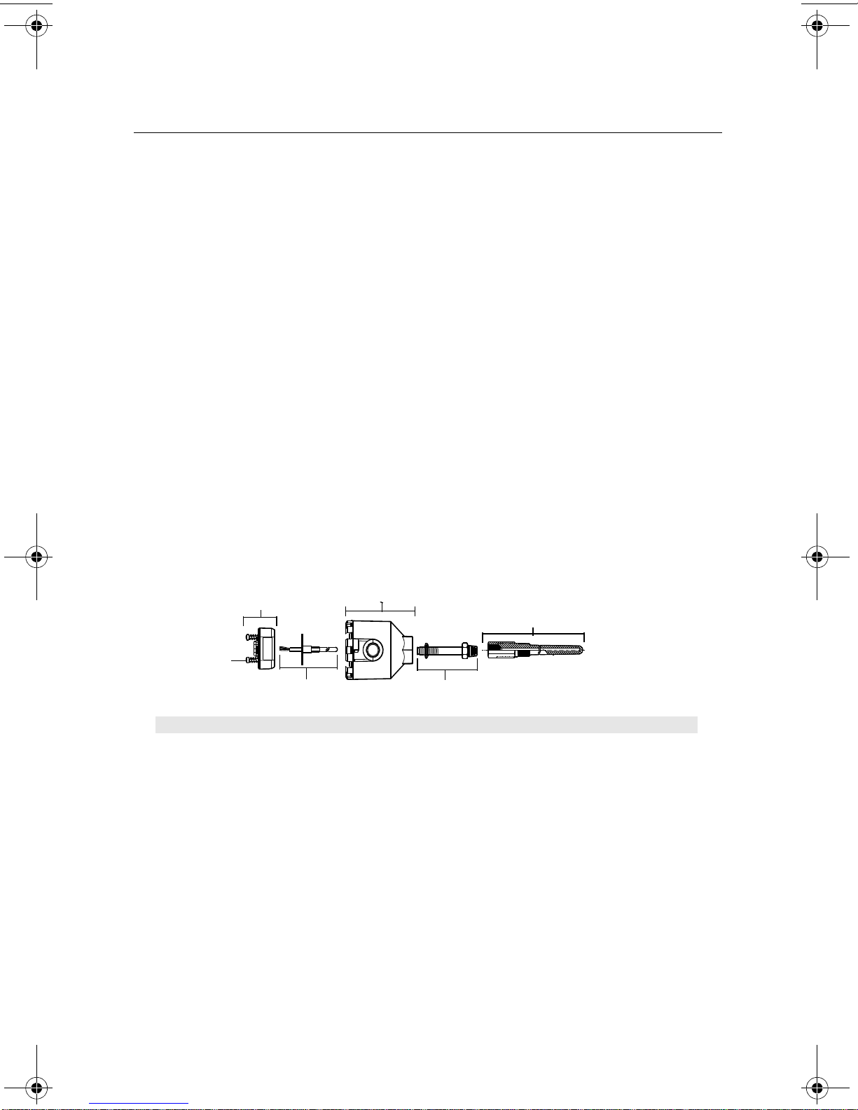
Typical Connection Head Installation
Head Mount Transmitter with DIN Plate Style Sensor
1. Attach the thermowell to the pipe or process container wall. Install and tighten the
thermowell before applying process pressure.
2. Assemble the transmitter to the sensor. Push the transmitter mounting screws through
the sensor mounting plate and insert the snap rings (optional) into the transmitter
mounting screw groove.
3. Wire the sensor to the transmitter (see Step 4:Connect the Wiring).
4. Insert the transmitter-sensor assembly into the connection head. Thread the transmitter
mounting screw into the connection head mounting holes. Assemble the extension to the
connection head. Insert the assembly into the thermowell.
5. Slip the shielded cable though the cable gland.
6. Attach a cable gland into the shielded cable.
7. Insert the shielded cable leads into the connection head through the cable entry.
Connect and tighten the cable gland.
8. Connect the shielded power cable leads to the transmitter power terminals. Avoid
contact with sensor leads and sensor connections.
9. Install and tighten the connection head cover. Enclosure covers must be fully engaged to
meet explosion-proof requirements.
A = 644H Transmitter D = Transmitter Mounting Screws
B = Connection Head E = Integral Mount Sensor with Flying Leads
C = Thermowell F = Extension
3

Quick Installation Guide
STEP 1 CONTINUED...
A
B
C
D
E
00825-0300-4728, Rev AA
Rosemount 644
July 2010
Typical Universal Head Installation
Head Mount Transmitter with Threaded Sensor
1. Attach the thermowell to the pipe or process container wall. Install and tighten
thermowells before applying process pressure.
2. Attach necessary extension nipples and adapters to the thermowell. Seal the nipple and
adapter threads with silicone tape.
3. Screw the sensor into the thermowell. Install drain seals if required for severe
environments or to satisfy code requirements.
4. Pull the sensor wiring leads through the universal head and transmitter. Mount the
transmitter in the universal head by threading the transmitter mounting screws into the
universal head mounting holes.
5. Mount the transmitter-sensor assembly into the thermowell. Seal adapter threads with
silicone tape.
6. Install conduit for field wiring to the conduit entry of the universal head. Seal conduit
threads with PTFE tape.
7. Pull the field wiring leads through the conduit into the universal head. Attach the sensor
and power leads to the transmitter. Avoid contact with other terminals.
8. Install and tighten the universal head cover. Enclosure covers must be fully engaged to
meet explosion-proof requirements.
A = Threaded Thermowell D = Universal Head (transmitter inside)
B = Threaded Style Sensor E = Conduit Entry
C = Standard Extension
4

Quick Installation Guide
STEP 2: WIRE AND APPLY POWER
1 2 3 4
Sensor Terminals
Communication Terminals
Power Terminals
2-wire
RTD and ⍀
3-wire RTD
and ⍀
4-wire RTD
and ⍀
T/C
and mV
**
*
1234
1234
1234
1234
00825-0300-4728, Rev AA
July 2010
Rosemount 644
• Wiring diagrams are located inside the terminal block cover and on the transmitter top
label.
• An external power supply is required to power a Profibus segment.
• The power required across the transmitter power terminals is 9 to 32 VDC (the power
terminals are rated to 32 VDC). To prevent damaging the transmitter, do not allow
terminal voltage to drop below 9 VDC when changing the configuration parameters.
Power Filter
A Profibus segment requires a power conditioner to isolate the power supply filter and
decouple the segment from other segments attached to the same power supply.
Power the Transmitter
1. Remove the terminal block cover (if applicable).
2. Connect the power lead to the power terminals (The 644 power terminals are polarity
insensitive for the Profibus protocol.)
3. Tighten the terminal screws. When tightening the sensor and power wires, the max
torque is 6 in.-lbs. (0.7 N-m).
4. Reattach and tighten the cover (if applicable).
5. Apply power (9 – 32 VDC).
* The transmitters must be configured for at least a 3-wire RTD in order to recognize an RTD with a
compensation loop.
** Emerson Process Management provides 4-wire sensors for all single element RTDs. Use these
RTDs in 3-wire configurations by leaving the unneeded leads disconnected and insulated with electrical
tape.
5
Sensor Connections Diagram

Rosemount 644
STEP 2 CONTINUED...
Profibus DP
RS-485 up to 12 MBd
PROFIBUS
Class 2
Master
(Configuration
Tool)
Terminators
6234 ft. (1900m) max
(Depending on cable characteristics)
Profibus PA
MBP-IS at 31.25KBd
Power/
Signal
Wiring
DP/PA
Coupler
Profibus Transmitter
Profibus Loop
Sensor Wires
Shield ground point
Transmitter
Typical Configuration for Profibus Networking
Quick Installation Guide
00825-0300-4728, Rev AA
July 2010
NOTE
1. Each segment in a Profibus trunk must be terminated at both ends.
2. Some DP/PA couplers contain the power supply, one terminator, and the power
3. The configuration tool is typically located in the control room.
Ground the Transmitter
Ungrounded Thermocouple, mV, and RTD/Ohm Inputs
Each process installation has different requirements for grounding. Use the grounding
options recommended by the facility for the specific sensor type, or begin with grounding
Option 1 (the most common).
Option 1:
1. Connect sensor wiring shield to the transmitter housing.
2. Ensure the sensor shield is electrically isolated from surrounding fixtures that may be
3. Ground signal wiring shield at the power supply end.
conditioner within the coupling device.
grounded.
6
 Loading...