

Page 1

Reference Manual
00809-0200-4728, Rev SD
March 2021
Rosemount™ 644 Temperature Transmitter
with HART® Protocol
Page 2

Safety messages
NOTICE
Read this document before working with the product. For personal and system safety, and for optimum product performance,
make sure you thoroughly understand the contents before installing, using, or maintaining this product. For technical assistance,
contacts are listed below:
Customer Central
Technical support, quoting, and order-related questions.
United States - 1-800-999-9307 (7:00 am to 7:00 pm Central Time)
Asia Pacific- 65 777 8211
Europe/Middle East/Africa - 49 (8153) 9390
North American Response Center
Equipment service needs.
1-800-654-7768 (24 hours—includes Canada)
Outside of these areas, contact your local Emerson representative.
WARNING
Follow instruction
Failure to follow these installation guidelines could result in death or serious injury.
Ensure only qualified personnel perform the installation.
Explosion
Explosions could result in death or serious injury.
Do not remove the connection head cover in explosive atmospheres when the circuit is live.
Before connecting a handheld communicator in an explosive atmosphere, ensure that the instruments in the loop are
installed in accordance with intrinsically safe or non-incendive field wiring practices.
Verify that the operating atmosphere of the transmitter is consistent with the appropriate hazardous locations certifications.
All connection head covers must be fully engaged to meet explosion-proof requirements.
Process leaks
Process leaks could result in death or serious injury.
Do not remove the thermowell while in operation.
Install and tighten thermowells and sensors before applying pressure.
Electric shock
Electrical shock could cause death or serious injury.
Use extreme caution when making contact with the leads and terminals.
The products described in this document are NOT designed for nuclear-qualified applications.
Using non-nuclear qualified products in applications that require nuclear-qualified hardware or products may cause inaccurate
readings.
For information on Rosemount nuclear-qualified products, contact your local Emerson Sales Representative.
Physical access
Unauthorized personnel may potentially cause significant damage to and/or misconfiguration of end users’ equipment. This could
be intentional or unintentional and needs to be protected against.
Physical security is an important part of any security program and fundamental to protecting your system. Restrict physical access
by unauthorized personnel to protect end users’ assets. This is true for all systems used within the facility.
2
Page 3

CAUTION
Conduit/cable entries
The conduit/cable entries in the transmitter housing use a ½–14 NPT thread form.
When installing in a hazardous location, use only appropriately listed or Ex certified plugs, glands, or adapters in cable/conduit
entries.
Unless otherwise marked, the conduit/cable entries in the housing enclosure use a ½–14 NPT form. Only use plugs, adapters,
glands, or conduit with a compatible thread form when closing these entries.
Unless marked, the conduit/cable entries in the transmitter housing use a ½–14 NPT thread form. Entries marked “M20” are
M20 × 1.5 thread form. On devices with multiple conduit entries, all entries will have the same thread form. Only use plugs,
adapters, glands, or conduit with a compatible thread form when closing these entries.
Only use plugs, adapters, glands, or conduit with a compatible thread form when closing these entries.
3
Page 4

4
Page 5

Reference Manual Contents
00809-0200-4728 March 2021
Contents
Chapter 1 Introduction.............................................................................................................. 7
1.1 Using this manual........................................................................................................................ 7
Chapter 2 Configuration...........................................................................................................11
2.1 Overview................................................................................................................................... 11
2.2 Safety messages........................................................................................................................ 11
2.3 System readiness.......................................................................................................................12
2.4 Configuration methods..............................................................................................................13
2.5 Verify configuration...................................................................................................................18
2.6 Basic configuration of the transmitter........................................................................................20
2.7 Configure dual sensor options................................................................................................... 26
2.8 Configure device outputs...........................................................................................................33
2.9 Inputting device information..................................................................................................... 40
2.10 Configure measurement filtering.............................................................................................42
2.11 Diagnostics and service............................................................................................................44
2.12 Establishing multi-drop communication..................................................................................49
2.13 Using the transmitter with the HART Tri-Loop..........................................................................51
2.14 Transmitter security ................................................................................................................54
Chapter 3 Hardware Installation.............................................................................................. 57
3.1 Overview................................................................................................................................... 57
3.2 Safety messages........................................................................................................................ 57
3.3 Considerations...........................................................................................................................58
3.4 Installation procedures.............................................................................................................. 61
Chapter 4 Electrical Installation................................................................................................73
4.1 Overview................................................................................................................................... 73
4.2 Safety messages........................................................................................................................ 73
4.3 Wiring and powering the transmitter.........................................................................................74
Chapter 5 Operation and Maintenance.....................................................................................85
5.1 Overview................................................................................................................................... 85
5.2 Safety messages........................................................................................................................ 85
5.3 Calibration overview..................................................................................................................87
5.4 Sensor input trim.......................................................................................................................88
5.5 Trim the analog output..............................................................................................................91
5.6 Transmitter-sensor matching.................................................................................................... 93
5.7 Switching HART Revision........................................................................................................... 95
Chapter 6 Troubleshooting...................................................................................................... 97
6.1 Overview................................................................................................................................... 97
Emerson.com/Rosemount 5
Page 6

Contents Reference Manual
March 2021 00809-0200-4728
6.2 Safety messages........................................................................................................................ 97
6.3 4–20 mA/HART output.............................................................................................................. 99
6.4 Diagnostic messages............................................................................................................... 101
6.5 Return of materials.................................................................................................................. 106
Chapter 7 Safety Instrumented Systems (SIS) Certification..................................................... 107
7.1 SIS certification........................................................................................................................107
7.2 Safety certified identification...................................................................................................107
7.3 Installation...............................................................................................................................107
7.4 Configuration.......................................................................................................................... 108
7.5 Operation and maintenance.................................................................................................... 109
7.6 Specifications.......................................................................................................................... 111
Appendix A Reference Data.......................................................................................................113
A.1 Product certifications.............................................................................................................. 113
A.2 Ordering information, specifications, and drawings.................................................................113
A.3 AMS terms...............................................................................................................................114
Appendix B Field Communicator Menu Trees and Fast Keys.......................................................115
B.1 Field Communicator menu trees..............................................................................................115
B.2 Field Communicator Fast Keys................................................................................................. 121
Appendix C Local Operator Interface (LOI)................................................................................ 125
C.1 Number entry..........................................................................................................................126
C.2 Text entry................................................................................................................................127
C.3 Timeout...................................................................................................................................129
C.4 Saving and canceling............................................................................................................... 129
C.5 LOI menu tree..........................................................................................................................131
C.6 LOI menu tree – extended menu............................................................................................. 132
6 Emerson.com/Rosemount
Page 7

Reference Manual
00809-0200-4728 March 2021
Introduction
1 Introduction
1.1 Using this manual
This manual is designed to assist in the installation, operation, and maintenance of
Rosemount 644 Head Mount, Field Mount, and Rail Mount Transmitters with the HART
protocol.
Configuration provides instruction the commissioning and operating the Rosemount 644
HART Transmitter. The information explains how to configure software functions and
many configuration parameters on an Asset Management System, a Field Communicator,
and the Local Operator Interface display option.
Hardware Installation contains mechanical installation instructions for the transmitter.
Electrical Installation contains electrical installation instructions and considerations for the
transmitter.
Operation and Maintenance contains common operation and maintenance techniques for
the transmitter.
Troubleshooting provides troubleshooting techniques for the most common transmitter
operating problems.
Safety Instrumented Systems (SIS) Certification provides identification, installation,
configuration, operation and maintenance, and inspection information for Safety
Instrumented Systems as it pertains to the Rosemount 644 Head Mount and Field Mount
Temperature Transmitter.
Reference Data supplies procedure on how to get the specifications, ordering information,
and product certification.
Field Communicator Menu Trees and Fast Keys contains Field Communicator menu trees
and Field Communicator Fast Keys.
®
Local Operator Interface (LOI) contains instructions for number entry, text entry, as well as
the LOI menu tree and LOI extended menu tree.
1.1.1
Emerson.com/Rosemount 7
Transmitter overview
The Rosemount 644 Head Mount and Field Mount Temperature Transmitters support the
following features:
• HART® configuration with Selectable HART revision capability (Revisions 5 or 7)
• Accepts either one or two inputs from a wide variety of sensor types (2-, 3-, and 4-wire
RTD, thermocouple, mV and ohm)
• A compact transmitter size with electronics completely encapsulated in protective
silicone and enclosed in a plastic housing ensuring long-term transmitter reliability
• Optional Safety Certification Option (IEC 61508 SIL 2)
• Optional enhanced accuracy and stability performance
• Optional LCD display with extended temperature ratings of -40 to 185 °F (-40 to 85 °C)
Page 8

Introduction Reference Manual
March 2021 00809-0200-4728
• Optional advanced LCD display with local operator interface (LOI)
• The Rosemount 644 Head Mount Transmitter is available in two housing materials
(Aluminum and SST) and various housing options that allow for mounting flexibility in a
variety of environmental conditions. The Rosemount 644 Field Mount is available in an
aluminum housing.
• Special dual-sensor features include Hot Backup™, Sensor Drift Alert, first good,
differential and average temperature measurements, and four simultaneous
measurement variable outputs in addition to the analog output signal.
• Additional advanced features include: Thermocouple degradation diagnostic, which
monitors thermocouple health, and process and transmitter minimum/maximum
temperature tracking.
The Rosemount 644 Rail Mount Temperature Transmitter supports the following features:
• 4–20 mA/HART protocol (Revision 5)
• Accepts one sensor input from a wide variety of sensor types (2-, 3-, and 4-wire RTD,
Thermocouple, mV and ohm)
• Completely encapsulated electronics to ensure long term transmitter reliability
Refer to the following literature for a full range of compatible connection heads, sensors,
and thermowells provided by Emerson.
• Rosemount Volume 1 Temperature Sensors and Accessories (English) Product Data
Sheet
• Rosemount DIN-Style Temperature Sensors and Thermowells (Metric) Product Data
Sheet
Table 1-1 and Table 1-2 below summarize changes in the Rosemount 644 Head Mount and
Rail Mount HART device revisions, respectively.
Table 1-1: Head Mount HART Revisions
Identify device Field device driver
Software
release date
Feb-2020 1.1.xx 1.0.xx 4
Aug-2012 1.1.xx 1.0.xx 3 7 9
(1) NAMUR Software Revision is located in the hardware tag of the device. HART Software Revision
can be read using a HART-capable configuration tool.
(2) Device Driver file names use Device and DD Revision ( e.g. 10_07). HART Protocol is designed to
enable legacy driver revisions to continue to communicate with new HART devices. To access this
functionality, the new device driver must be downloaded. It is recommended to download the
new device driver to ensure new functionality.
NAMUR
software
revision
NAMUR
hardware
revision
(1)
HART
software
revision
HART
universal
revision
7 9
5 8
(2)
Device
revision
Review
instructions
Manual
document
number
00809-0200-
4728
00809-0200-
4728
8 Emerson.com/Rosemount
Page 9

Reference Manual Introduction
00809-0200-4728 March 2021
Table 1-2: Rail Mount HART Revisions
Railmount
Rosemount 644 Hardware revision 31
Device revision 7
HART revision 5
Emerson.com/Rosemount 9
Page 10

Introduction Reference Manual
March 2021 00809-0200-4728
10 Emerson.com/Rosemount
Page 11

Reference Manual Configuration
00809-0200-4728 March 2021
2 Configuration
2.1 Overview
This section contains information on commissioning and tasks that should be performed
on the bench prior to installation. Field Communicator, AMS Device Manager, and Local
Operator Interface (LOI) instructions are given to perform configuration functions. For
convenience, Field Communicator Fast Key sequences are labeled “Fast Keys,” and
abbreviated LOI menus are provided for each function below. The LOI is only available on
the Rosemount 644 Head Mount and Field Mount designs, and the configuration
instructions referencing the interface will not apply to the rail mount form factor.
Full Field Communicator menu trees and Fast Key sequences are available in Field
Communicator Menu Trees and Fast Keys. Local operator interface menu trees are
available in Local Operator Interface (LOI).
2.2 Safety messages
Instructions and procedures in this section may require special precautions to ensure the
safety of the personnel performing the operations. Refer to the following safety messages
before performing an operation preceded by this symbol.
WARNING
Follow instruction
Failure to follow these installation guidelines could result in death or serious injury.
Ensure only qualified personnel perform the installation.
Explosion
Explosions could result in death or serious injury.
Do not remove the connection head cover in explosive atmospheres when the circuit is
live.
Before connecting a handheld communicator in an explosive atmosphere, ensure that
the instruments in the loop are installed in accordance with intrinsically safe or nonincendive field wiring practices.
Verify that the operating atmosphere of the transmitter is consistent with the
appropriate hazardous locations certifications.
All connection head covers must be fully engaged to meet explosion-proof
requirements.
Process leaks
Process leaks could result in death or serious injury.
Do not remove the thermowell while in operation.
Install and tighten thermowells and sensors before applying pressure.
Emerson.com/Rosemount 11
Page 12

Configuration Reference Manual
March 2021 00809-0200-4728
WARNING
Electric shock
Electrical shock could cause death or serious injury.
Use extreme caution when making contact with the leads and terminals.
Physical access
Unauthorized personnel may potentially cause significant damage to and/or
misconfiguration of end users’ equipment. This could be intentional or unintentional and
needs to be protected against.
Physical security is an important part of any security program and fundamental to
protecting your system. Restrict physical access by unauthorized personnel to protect end
users’ assets. This is true for all systems used within the facility.
2.3 System readiness
2.3.1 Confirm HART revision capability
If using HART®-based control or asset management systems, confirm the HART capability
of those systems prior to transmitter installation. Not all systems are capable of
communicating with HART Revision 7 protocol. This transmitter can be configured for
either HART Revision 5 or 7.
For instructions on how to change the HART revision of your transmitter, see Switching
HART Revision.
12 Emerson.com/Rosemount
Page 13

Reference Manual Configuration
00809-0200-4728 March 2021
2.3.2 Confirm correct device driver
• Verify the latest Device Driver files are loaded on your systems to ensure proper
communications.
• Download the latest Device Driver at Emerson.com/Rosemount or Fieldcomm.org.
Table 2-1: Rosemount 644 Device Revisions and Files
Software date Identify device Find device driver files
NAMUR
Date
June 2012 1.1.1 01
(1) NAMUR Software Revision is located on the hardware tag of the device. HART Software Revision can be read using a
HART Communication tool.
(2) Device Driver file names use Device and DD Revision (e.g. 10_01). HART Protocol is designed to enable legacy device
driver revisions to continue to communicate with new HART devices. To access new functionality, the new Device Driver
must be downloaded. It is recommended to download the new Device Driver files to ensure full functionality.
(3) HART Revision 5 and 7 Selectable. Dual Sensor support, Safety Certified, Advanced Diagnostics (if ordered), Enhanced
Accuracy, and Stability (if ordered).
2.3.3
software
revision
Surges/transients
®
HART
software
revision
HART
Universal
revision
(1)
5 8 Rosemount
7 9
Device
revision
(2)
Review
instructions
Document
644
Temperature
Transmitter
Reference
Manual
Review
functionality
Changes to
software
(3)
See
for list of
changes
The transmitter will withstand electrical transients of the energy level encountered in
static discharges or induced switching transients. However, high-energy transients, such
as those induced in wiring from nearby lightning strikes, welding, heavy electrical
equipment, or switching gears, can damage both the transmitter and the sensor. To
protect against high-energy transients, install the transmitter into a suitable connection
head with the integral transient protector, option T1. Refer to the Rosemount 644 Product
Data Sheet for more information.
(3)
2.4 Configuration methods
CAUTION
Commisioning
Set all transmitter hardware adjustments during commissioning to avoid exposing the
transmitter electronics to the plant environment after installation.
The transmitter can be configured either before or after installation. Configuring the
transmitter on the bench using either a Field Communicator, AMS Device Manager, or LOI
ensures all transmitter components are in working order prior to installation.
Emerson.com/Rosemount 13
Page 14
A
B
C
D
E
A
B
C
D
E
+
+
+
+
_
_
_
_
Configuration Reference Manual
March 2021 00809-0200-4728
The transmitter can be configured either on-line or off-line using a Field Communicator,
AMS Device Manager, or the optional LOI (head-mount and field-mount). During on-line
configuration, the transmitter is connected to a Field communicator. Data is entered in
the working register of the communicator and sent directly to the transmitter.
Off-line configuration consists of storing configuration data in a Field Communicator while
it is not connected to a transmitter. Data is stored in nonvolatile memory and can be
downloaded to the transmitter at a later time.
2.4.1 Configuring on the bench
To configure on the bench, required equipment includes a power supply, a digital
multimeter (DMM), and Field Communicator, AMS Device Manager, or a LOI – option M4.
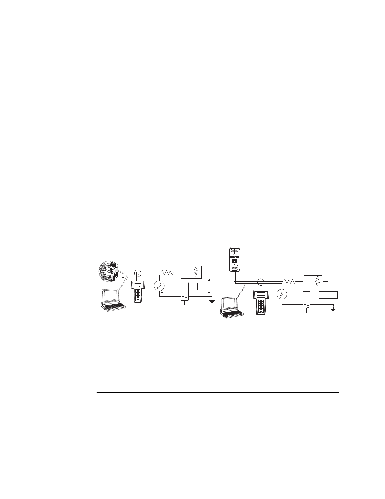
Connect the equipment as shown in Figure 2-1. Connect HART® Communication leads at
any termination point in the signal loop. To ensure successful HART Communication, a
resistance of at least 250 ohms must be present between the transmitter and the power
supply. Connect the Field Communicator leads to the clips behind the power (+,–)
terminals on the top of the device. Avoid exposing the transmitter electronics to the plant
environment after installation by setting all transmitter jumpers during the
commissioning stage on the bench.
Figure 2-1: Powering the Transmitter for Bench Configuration
Head mount and Field mount Rail mount
A. Field communicator
B. Power supply
C. 248 Ω ≤ RL ≤ 1100 Ω
D. Recorder (optional)
E. Ammeter (optional)
Note
• Signal loop may be grounded at any point or left ungrounded.
• A Field Communicator may be connected at any termination point in the signal loop.
The signal loop must have between 250 and 1100 ohms load for communications.
• Max torque is 6 in-lb (0.7 N-m).
14 Emerson.com/Rosemount
Page 15
Reference Manual Configuration
00809-0200-4728 March 2021
2.4.2 Selecting a configuration tool
Field Communicator
The Field Communicator is a handheld device that exchanges information with the
transmitter from the control room, the instrument site, or any wiring termination point in
the loop. To facilitate communication, connect the Field Communicator, shown in this
manual, in parallel with the transmitter (see Figure 2-1). Use the loop connection ports on
the rear panel of the Field Communicator. The connections are non-polarized. Do not
make connections to the serial port or the nickel cadmium (NiCd) recharger jack in
explosive atmospheres. Before connecting the Field Communicator in an explosive
atmosphere make sure the instruments in the loop are installed in accordance with
intrinsically safe or non-incendive field wiring practices.
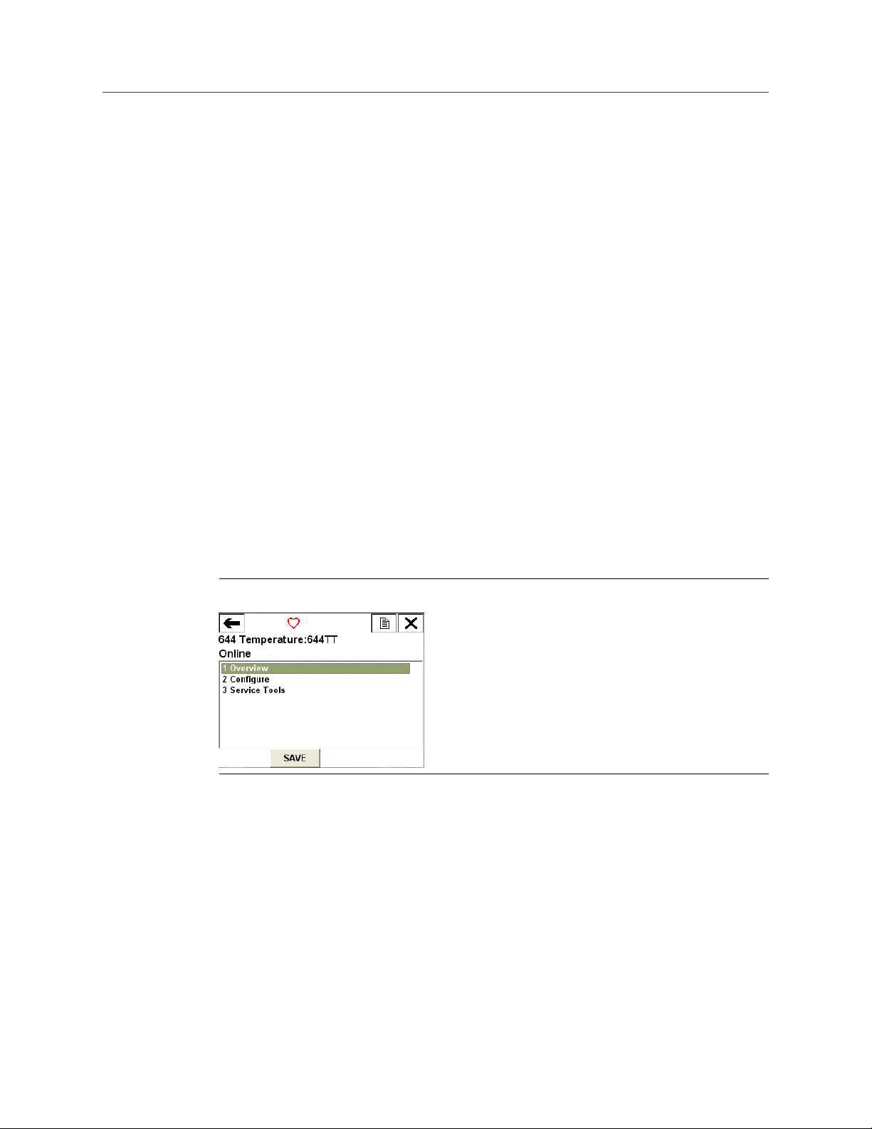
There are two interfaces available with the Field Communicator: Traditional and
Dashboard interfaces. All steps using a Field Communicator will be using Dashboard
interfaces. Figure 2-2 shows the Device Dashboard interface. As stated in System
readiness, it is critical that the latest DD’s are loaded into the Field Communicator for
optimal transmitter performance.
Visit Emerson.com/Rosemount to download latest DD library.
Turn on the Field Communicator by pressing the ON/OFF key. The Field Communicator will
search for a HART®-compatible device and indicate when the connection is made. If the
Field Communicator fails to connect, it indicates that no device was found. If this occurs,
refer to Troubleshooting.
Figure 2-2: Field Communicator Device Dashboard Interface
Field Communicator menu trees and Fast Keys are available in Field Communicator Menu
Trees and Fast Keys
AMS Device Manager
With an AMS Device Manager software package, you can commission and configure
instruments, monitor status and alerts, troubleshoot from the control room, perform
advanced diagnostics, manage calibration, and automatically document activities with a
single application.
Full configuration capability with AMS Device Manager requires loading the most current
Device Descriptor (DD) for this device. Download the latest DD at Emerson.com/
Rosemount or Fieldcomm.org.
Emerson.com/Rosemount 15
Page 16
Configuration Reference Manual
March 2021 00809-0200-4728
Note
All steps listed in this product manual using AMS Device Manager assume the use of
Version 11.5.
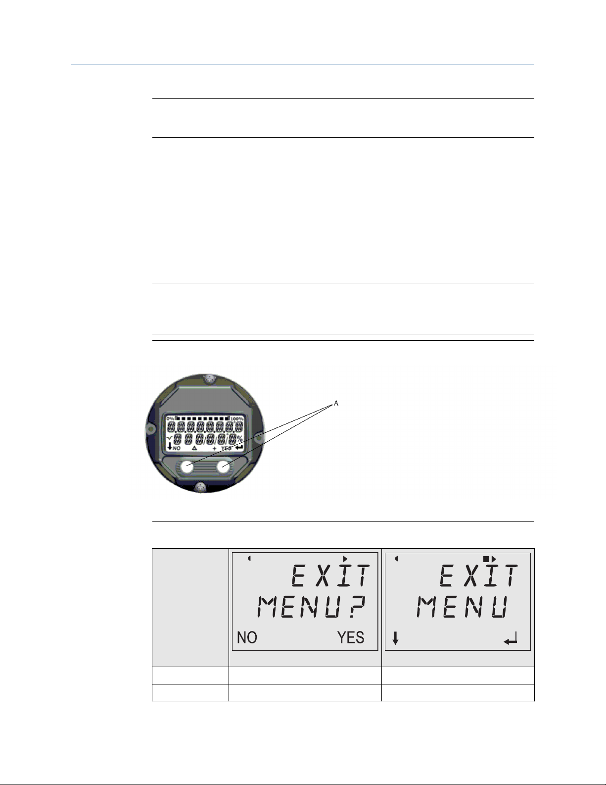
Local Operator Interface (LOI)
• The LOI requires option code M4 to be ordered.
• To activate the LOI, push either configuration button. Configuration buttons are
located on the LCD display (remove the housing cover to access the interface. See
Table 2-2 for configuration button functionality and Figure 2-3 for configuration button
location.)
When using the LOI for configuration, several features require multiple screens for a
successful configuration. Data entered will be saved on a screen-by-screen basis; the LOI
will indicate this by flashing SAVED on the LCD display each time.
Note
Entering into the LOI menu effectively disables the ability to write to the device by any
other host or configuration tool. Ensure this is communicated to necessary personnel
before using the LOI for device configuration.
Figure 2-3: LOI Configuration Buttons
A. Configuration buttons
Table 2-2: LOI Button Operation
Button
Left No SCROLL
Right Yes ENTER
16 Emerson.com/Rosemount
Page 17

Reference Manual Configuration
00809-0200-4728 March 2021
LOI password
An LOI password can be entered and enabled to prevent review and modification of device
configuration via the LOI. This does not prevent configuration from HART® or through the
control system. The LOI password is a four-digit code that is to be set by the user. If the
password is lost or forgotten the master password is “9307”. The LOI password can be
configured and enabled/disabled by HART communication via a Field Communicator, AMS
Device Manager, or the LOI.
2.4.3 Setting the loop to manual
When sending or requesting data that would disrupt the loop or change the output of the
transmitter, set the process application loop to manual. The Field Communicator, AMS
Device Manager, or LOI will prompt you to set the loop to manual when necessary.
Acknowledging this prompt does not set the loop to manual. The prompt is only a
reminder; set the loop to manual as a separate operation.
2.4.4
2.4.5
Failure mode
As part of normal operation, each transmitter continuously monitors its own performance.
This automatic diagnostics routine is a timed series of checks repeated continuously. If
diagnostics detect an input sensor failure or a failure in the transmitter electronics, the
transmitter drives its output to low or high depending on the position of the failure mode
switch. If the sensor temperature is outside the range limits, the transmitter saturates its
output to 3.9 mA for standard configuration on the low end (3.8 mA if configured for
NAMUR-compliant operation) and 20.5 mA on the high end (or NAMUR-compliant). These
values are also custom configurable by the factory or using the Field Communicator. The
values to which the transmitter drives its output in failure mode depend on whether it is
configured to standard, NAMUR-compliant, or custom operation. See Rosemount 644
Temperature Transmitter Product Data Sheet for standard and NAMUR-compliant
operation parameters.
HART software lock
The HART® software lock prevents changes to the transmitter configuration from all
sources; all changes requested via HART by the Field Communicator, AMS Device manager
or the LOI will be rejected. The HART Lock can only be set via HART Communication, and is
only available in HART Revision 7 mode. The HART Lock can be enabled or disabled with a
Field Communicator or AMS Device Manager.
Lock HART software using the Field Communicator
From the HOME screen, enter the Fast Key sequence.
Device Dashboard Fast Keys
3, 2, 1
Lock HART software using the AMS Device Manager
Procedure
1. Right click on the device and select Configure.
Emerson.com/Rosemount 17
Page 18

Configuration Reference Manual
March 2021 00809-0200-4728
2. Under Manual Setup select the Security tab.
3. Select the Lock/Unlock button under HART Lock (Software) and follow the screen
prompts.
2.5 Verify configuration
It is recommended that various configuration parameters are verified prior to installation
into the process. The various parameters are detailed out for each configuration tool.
Depending on what configuration tool(s) are available, follow the steps listed relevant to
each tool.
2.5.1 Verify configuration using the Field Communicator
Configuration parameters listed in Table 2-3 below are the basic parameters that should
be reviewed prior to transmitter installation. A full list of configuration parameters that
can be reviewed and configured using a Field Communicator are located in Field
Communicator Menu Trees and Fast Keys. A Rosemount 644 Device Descriptor (DD) must
be installed on the Field Communicator to verify configuration.
Verify device configuration using Fast Key sequences in Table 2-3.
From the HOME screen, enter the Fast Key sequences listed in Table 2-3.
Table 2-3: Device Dashboard Fast Key Sequences
Function HART 5 HART 7
Alarm Values 2, 2, 5, 6 2, 2, 5, 6
Damping Values 2, 2, 1, 5 2, 2, 1, 6
Lower Range Value (LRV) 2, 2, 5, 5, 3 2, 2, 5, 5, 3
Upper Range Value (URV) 2, 2, 5, 5, 2 2, 2, 5, 5, 2
Primary Variable 2, 2, 5, 5, 1 2, 2, 5, 5, 1
Sensor 1 Configuration 2, 1, 1 2, 1, 1
Sensor 2 Configuration
Tag 2, 2, 7, 1, 1 2, 2, 7, 1, 1
Units 2, 2, 1, 5 2, 2, 1, 4
(1) Available only if option code (S) or (D) is ordered.
(1)
2, 1, 1 2, 1, 1
18 Emerson.com/Rosemount
Page 19

Reference Manual Configuration
00809-0200-4728 March 2021
2.5.2 Verify configuration using the AMS Device Manager
Procedure
1. Right click on the device and select Configuration Properties from the menu.
2. Navigate the tabs to review the transmitter configuration data.
2.5.3 Verify configuration using the LOI
Procedure
1. Press any configuration button to activate the LOI.
2. Select VIEW CONFIG to review the below parameters.
3. Use the configuration buttons to navigate through the menu.
The parameters to be reviewed prior to installation include:
• Tag
• Sensor configuration
2.5.4
• Units
• Alarm and saturation levels
• Primary variable
• Range values
• Damping
Checking transmitter output
Before performing other transmitter on-line operations, review the transmitter digital
output parameters to ensure that the transmitter is operating properly and is configured
to the appropriate process variables.
Checking or setting process variables
The “Process Variables” menu displays process variables, including sensor temperature,
percent of range, analog output, and terminal temperature. These process variables are
continuously updated. The default primary variable is Sensor 1. The secondary variable is
the transmitter terminal temperature by default.
Check or set process variables using the Field Communicator
From the HOME screen, enter the Fast Key sequence.
Device Dashboard Fast Keys
Emerson.com/Rosemount 19
3, 2, 1
Page 20
ON/OFF
VIEW CONFIG
ZERO TRIM
UNITS
RERANGE
LOOP TEST
DISPLAY
EXTENDED MENU
EXIT MENU
SENSOR 1
SENSOR 2*
ANALOG
PV
AVG
1ST GOOD
DIFF
% RANGE
TERM
MNMAX1*
MNMAX2*
MNMAX3*
MNMAX4*
BACK TO MENU
EXIT MENU
Configuration Reference Manual
March 2021 00809-0200-4728
Check or set process variables using the AMS Device Manager
Procedure
• Right click on the device and select Service Tools from the menu.
The Variables tab displays the following process variables:
— Primary, second, third, and fourth variables, as well as the analog output.
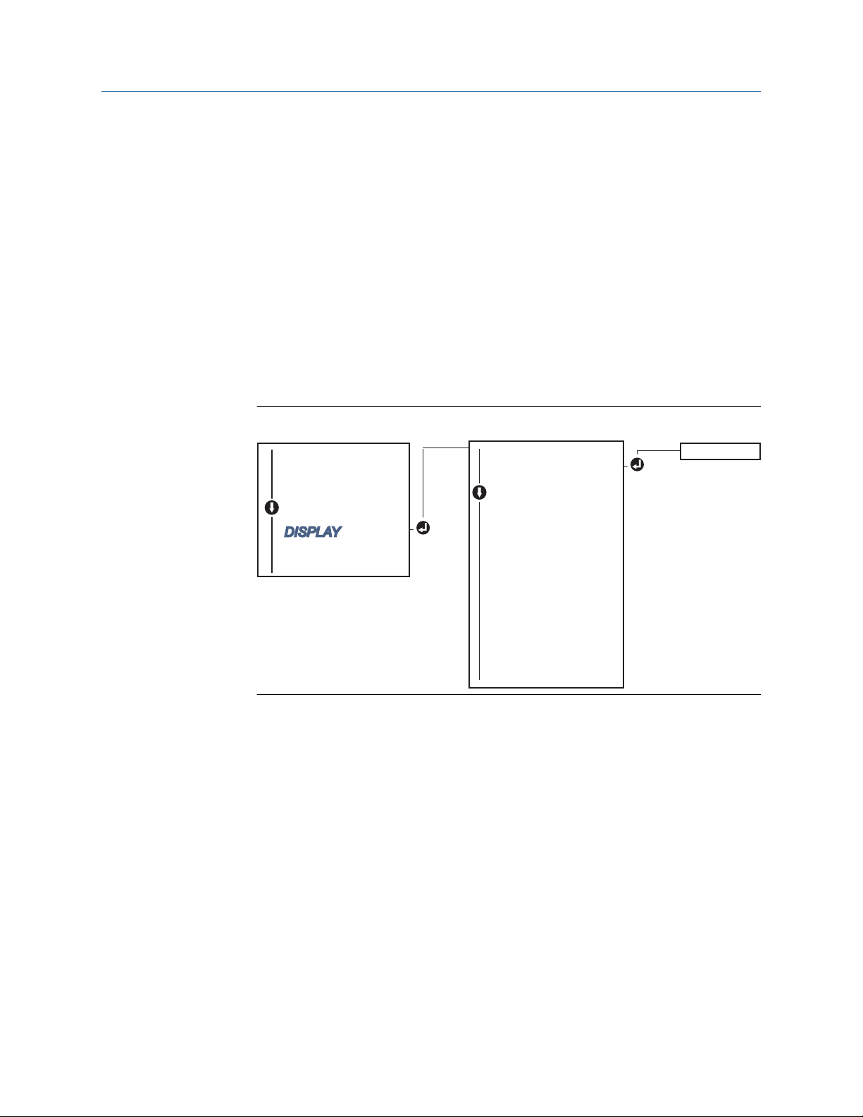
Check or set process variables using LOI
Procedure
1. To check the process variables from the LOI, the user must first configure the
display to show the desired variables (see Configuring the LCD display).
2. Once the desired device variables are chosen, simply exit the LOI menu and view the
alternating values on the display screen.
Figure 2-4: Check or set process variables using LOI
2.6 Basic configuration of the transmitter
20 Emerson.com/Rosemount
The transmitter must be configured for certain basic variables in order to be operational.
In many cases, all of these variables are pre-configured at the factory. Configuration may
be required if the transmitter is not configured or if the configuration variables need
revision.
Page 21
CALIBRAT
DAMPING
VARIABLE MAP
TAG
ALM SAT VALUES
PASSWORD
....
RE-MAP PV
RE-MAP 2V
RE-MAP 3V
RE-MAP 4V
....
VIEW CONFIG
SENSOR CONFIG
UNITS
RERANGE
LOOP TEST
DISPLAY
EXTENDED MENU
EXIT MENU
Reference Manual Configuration
00809-0200-4728 March 2021
2.6.1 Mapping the HART variables
Mapping HART variables using the Field Communicator
The “Variable Mapping” menu displays the sequence of the process variables. Select the
sequence below to change this configuration. The transmitter single sensor input
configuration screens allow selection of the primary variable (PV) and the secondary
variable (SV). When the Select PV screen appears, Snsr 1 must be selected.
The transmitter dual-sensor option configuration screens allow selection of the Primary
Variable (PV), Secondary Variable (SV), Tertiary Variable (TV), and Quaternary Variable
(QV). Variable choices are Sensor 1, Sensor 2, Differential Temperature, Average
Temperature, Terminal Temperature, and Not Used. The 4–20 mA analog signal
represents the Primary Variable.
From the HOME screen, enter the Fast Key sequence.
Device Dashboard Fast Keys
2, 2, 8, 6
Mapping HART variables using the AMS Device Manager
Procedure
1. Right click on the device and select the Configure menu.
2. In the left navigation pane, select Manual Setup then on the HART tab.
3. Map each variable individually or use the Re-map Variables method to guide you
through the re-mapping process.
4. Select Apply when complete.
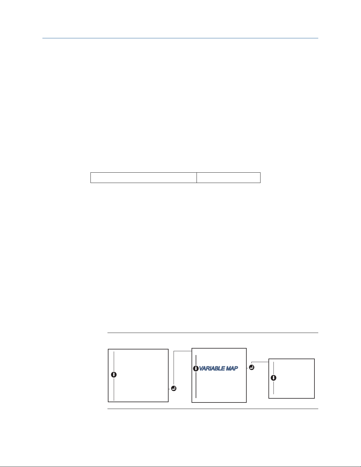
Mapping HART variables using LOI
Follow flow chart to select the desired mapped variables.
Procedure
1. Use the SCROLL and ENTER buttons to select each variable.
2. Save by selecting SAVE as indicated on the LCD screen when prompted.
See Figure 2-5 for an example of a mapped variable with the LOI.
Figure 2-5: Mapping Variables with LOI
Emerson.com/Rosemount 21
Page 22

Configuration Reference Manual
March 2021 00809-0200-4728
2.6.2 Configuring the sensor(s)
Sensor configuration includes setting the information for:
• Sensor type
• Connection type
• Units
• Damping values
• Sensor serial number
• RTD 2-wire offset
Configure the sensors using a Field Communicator
The configure sensors method will guide you through the configuration of all necessary
settings associated with configuring a sensor including:
For a full list of Sensor Types available with the Rosemount 644 Transmitter and their
associated levels of accuracy.
From the HOME screen, enter the Fast Key sequence.
Device Dashboard Fast Keys
2, 1, 1
Configure the sensors using AMS Device Manager
Procedure
1. Right click on the device and select Configure.
2. In the left navigation pane select Manual Setup and select the Sensor 1 or Sensor 2
tab depending on the need.
3. Individually select the sensor type, connection, units and other sensor related
information as desired from the drop down menus on the screen.
4. Select Apply when complete.
22 Emerson.com/Rosemount
Page 23
VIEW SENSOR
SENSOR CONFIG
BACK TO MENU
EXIT MENU
VIEW S1 CONFIG
VIEW S2 CONFIG*
BACK TO MENU
EXIT MENU
VIEW CONFIG
SENSOR CONFIG
UNITS
RERANGE
LOOP TEST
DISPLAY
EXTENDED MENU
EXIT MENU
SENSOR 1 CONFIG
SENSOR 2 CONFIG*
BACK TO MENU
EXIT MENU
Reference Manual Configuration
00809-0200-4728 March 2021
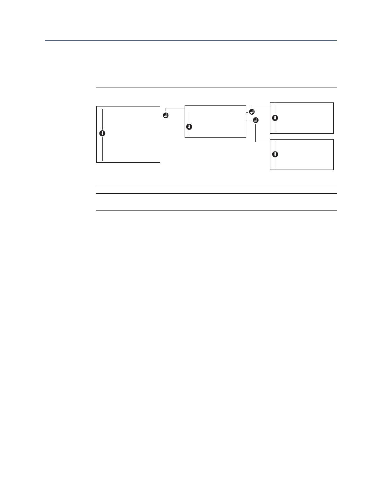
Configure sensors using LOI
Reference Figure 2-6 for guidance on where to find Sensor Configuration in the LOI menu.
Figure 2-6: Configuring Sensors with LOI
Note
Sensor 2 configuration is available only if option code (S) or (D) is ordered.
Contact an Emerson representative for information on the temperature sensors,
thermowells, and accessory mounting hardware that is available through Emerson.
Emerson.com/Rosemount 23
Page 24

Configuration Reference Manual
March 2021 00809-0200-4728
2.6.3 2-wire RTD offset
The 2-wire offset feature allows the measured lead wire resistance to be input and
corrected for, which results in the transmitter adjusting its temperature measurement for
the error caused by this added resistance. Because of a lack of lead wire compensation
within the RTD, temperature measurements made with a 2-wire RTD are often inaccurate.
This feature can be configured as a subset of the sensor configuration process in the Field
Communicator, AMS Device Manager, and the LOI.
To utilize this feature properly perform the following steps:
Procedure
1. Measure the lead wire resistance of both RTD leads after installing the 2-wire RTD
and transmitter.
2. Navigate to the 2-wire RTD Offset parameter.
3. Enter the total measured resistance of the two RTD leads at the 2-wire Offset
prompt to ensure proper adjustment. The transmitter will adjust its temperature
measurement to correct the error caused by lead wire resistance.
Set 2-wire RTD offset using the Field Communicator
From the HOME screen, enter the Fast Key sequence.
Device Dashboard Fast Keys
2, 1, 1
Set 2-wire RTD offset using the AMS Device Manager
Procedure
1. Right click on the device and select Configure.
2. In the left navigation pane select Manual Setup and select the Sensor 1 or Sensor 2
tab depending on the need. Find the 2-wire offset text field and enter the value.
3. Select Apply when complete.
24 Emerson.com/Rosemount
Page 25

Reference Manual Configuration
00809-0200-4728 March 2021
2.6.4 Setting output units
The Units can be configured for a number of different parameters in the Rosemount 644
Transmitter. Individual Units can be configured for:
• Sensor 1
• Sensor 2
• Terminal temperature
• Differential temperature
• Average temperature
• First good temperature
Each of the base parameters and calculated outputs from those values can have a unit of
measure associated with it. Set the transmitter output to one of the following engineering
units:
• Celsius
• Fahrenheit
• Rankine
• Kelvin
• Ohms
• Millivolts
Set output limits using Field Communicator
From the HOME screen, enter the Fast Key sequence.
Device Dashboard Fast Keys 2, 2, 1, 4 2, 2, 1, 5
HART 5 HART 7
Set output limits using AMS Device Manager
Procedure
1. Right click on the device and select Configure.
2. In the left navigation pane select Manual Setup. The unit fields for various variables
are spread over the Manual Setup tabs, click through the tabs and change the
desired units.
3. Select Apply when complete.
Emerson.com/Rosemount 25
Page 26
CHANGE ALL
SENSOR 1 UNITS
SENSOR 2 UNITS*
DIFF UNITS*
AVERAGE UNITS*
1ST GOOD UNITS**
BACK TO MENU
EXIT MENU
DEG C UNITS
DEG F UNITS
DEG R UNITS
KELVIN UNITS
MV UNITS
OHM UNITS
BACK TO MENU
EXIT MENU
VIEW CONFIG
SENSOR CONFIG
UNITS
RERANGE
LOOP TEST
DISPLAY
EXTENDED MENU
EXIT MENU
Configuration Reference Manual
March 2021 00809-0200-4728
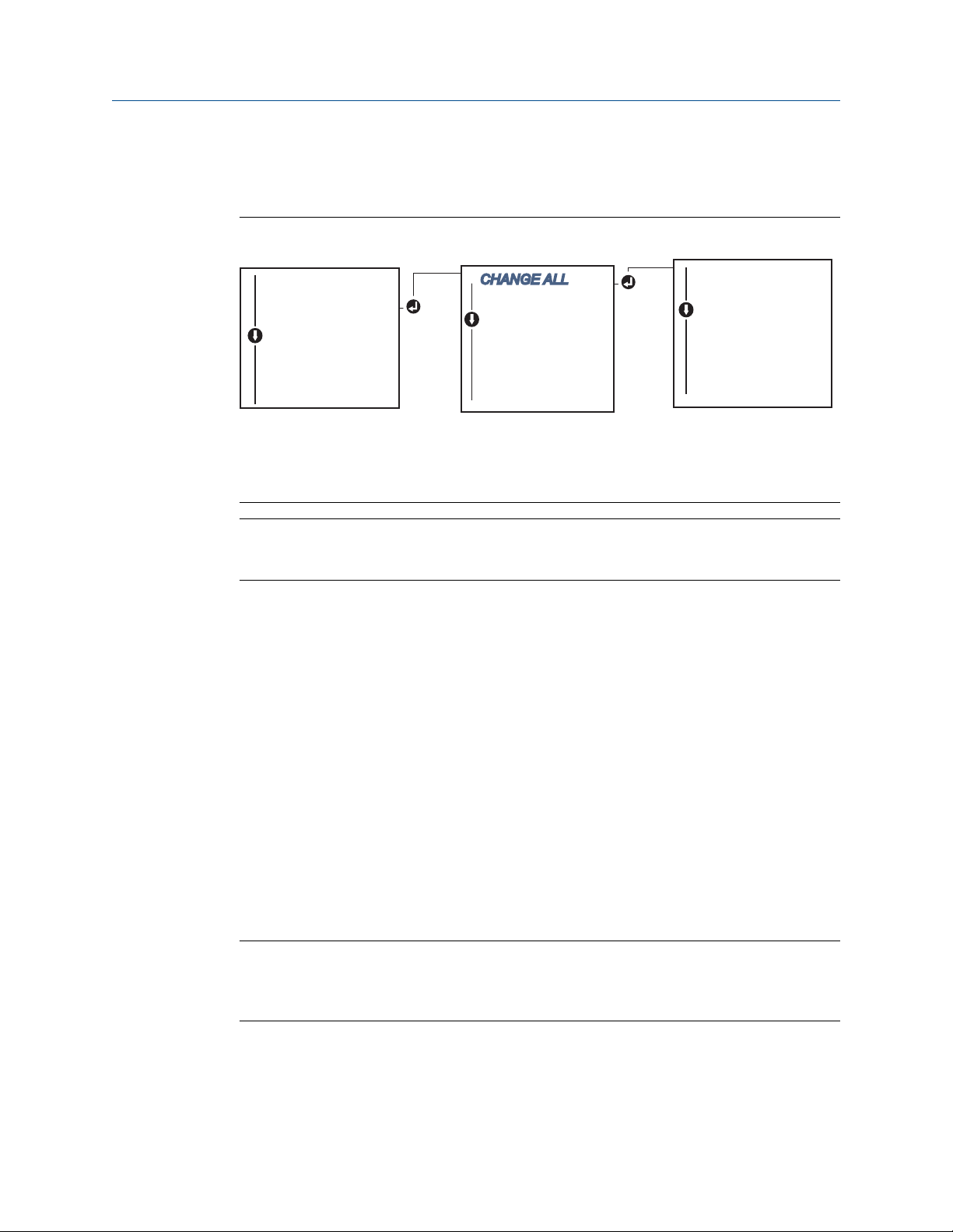
Set output limits using LOI
Reference the below image for where to find the Units configuration in the LOI menu.
Figure 2-7: Configuring Units with LOI
* Available only if option code (S) or (D) is ordered.
** Available only if option codes (S) and (DC) are both ordered, or if option codes (D) and
(DC) are both ordered.
Note
The list of choices available for Units after the primary menu is dependent on your Sensor
configuration settings.
2.7 Configure dual sensor options
Dual-sensor configuration deals with the functions that can be used with a transmitter
ordered with Dual Sensor inputs. In the Rosemount 644 Transmitter these functions
include:
• Differential temperature
• Average temperature
• Hot Backup™ and sensor drift alert diagnostics (requires option code DC)
— First good temperature (requires options S and DC, or options D and DC)
2.7.1
Differential temperature configuration
The Rosemount 644 Transmitter ordered and configured for dual-sensors can accept any
two inputs then display the differential temperature between them. Use the following
procedures to configure the transmitter to measure differential temperature.
Note
This procedure assumes the differential temperature is a calculated output of the device
but does not re-assign it as the primary variable. If it desired for Differential to be the
transmitter’s primary variable see Mapping the HART variables to set it to PV.
26 Emerson.com/Rosemount
Page 27
CHANGE ALL
SENSOR 1 UNITS
SENSOR 2 UNITS*
DIFFRNTL UNITS*
AVERAGE UNITS*
1ST GOOD UNITS**
BACK TO MENU
EXIT MENU
DEG C UNITS
DEG F UNITS
DEG R UNITS
KELVIN UNITS
MV UNITS
OHM UNITS
BACK TO MENU
EXIT MENU
VIEW CONFIG
SENSOR CONFIG
UNITS
RERANGE
LOOP TEST
DISPLAY
EXTENDED MENU
EXIT MENU
Reference Manual Configuration
00809-0200-4728 March 2021
Configure differential temperature configuration using Field Communicator
From the HOME screen, enter the Fast Key sequence.
Device Dashboard Fast Keys 2, 2, 3, 1
Configure differential temperature configuration using AMS Device Manager
Procedure
1. Right click on the device and select Configure.
2. In the left navigation pane choose Manual Setup.
3. On the Calculated Output Tab find the Differential Temperature group box.
4. Select Units and Damping settings then select Apply when complete.
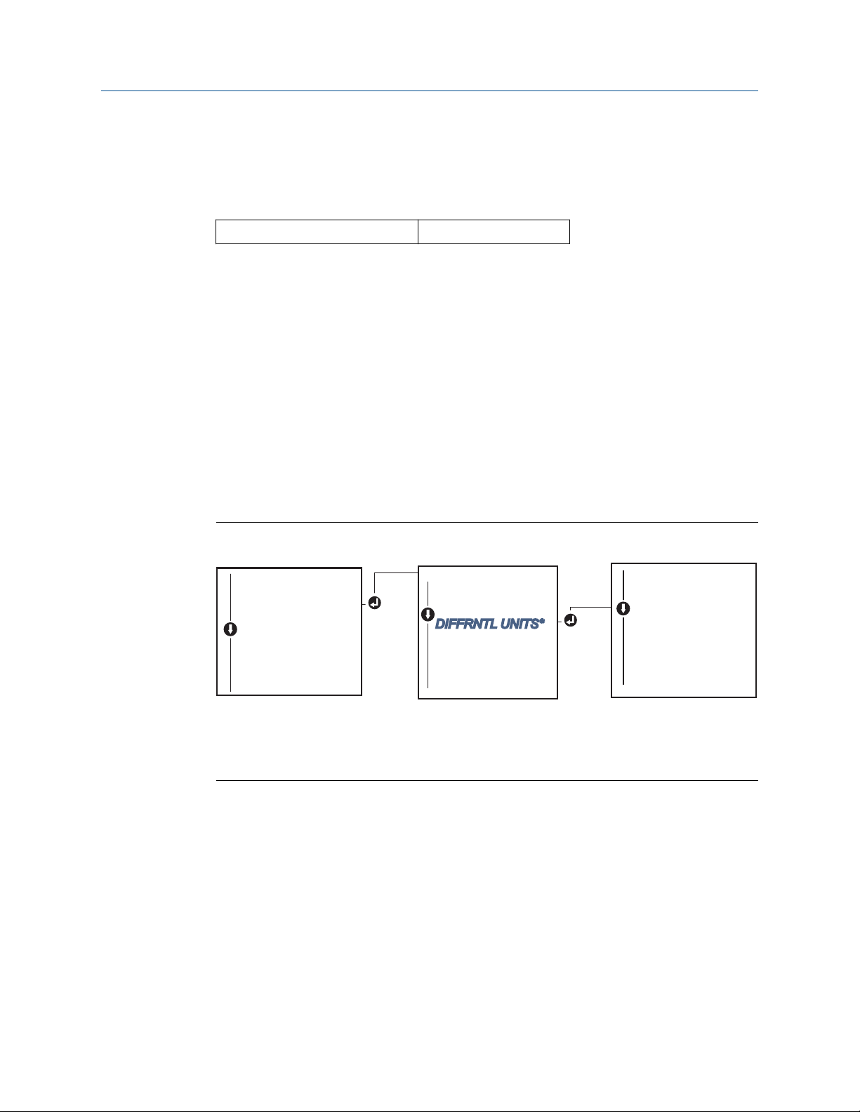
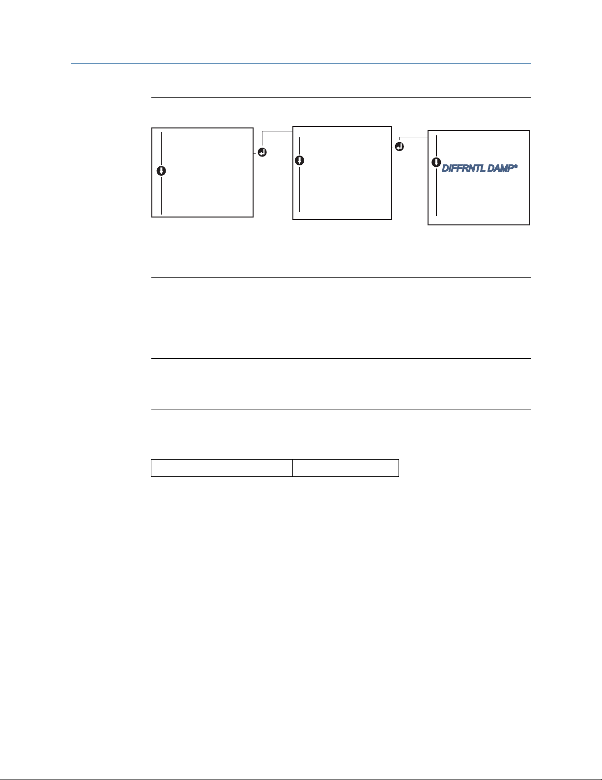
Configure differential temperature configuration using LOI
To configure the Differential Temperature on the LOI, the Units and Damping values must
be set separately. Reference figures below for where to find these in the menu.
Figure 2-8: Configuring Differential Units with LOI
* Available only if option code (S) or (D) is ordered.
** Available only if option codes (S) and (DC) are both ordered, or if option codes (D) and
(DC) are both ordered.
Emerson.com/Rosemount 27
Page 28
CALIBRAT
DAMPING
VARIABLE MAP
TAG
ALARM SAT VALUES
PASSWORD
....
PV DAMP
SENSOR 1 DAMP
SENSOR 2 DAMP*
DIFFRNTL DAMP*
AVERAGE DAMP*
1ST GOOD DAMP**
BACK TO MENU
EXIT MENU
VIEW CONFIG
SENSOR CONFIG
UNITS
RERANGE
LOOP TEST
DISPLAY
EXTENDED MENU
EXIT MENU
Configuration Reference Manual
March 2021 00809-0200-4728
Figure 2-9: Configuring Differential Damping with LOI
* Available only if option code (S) or (D) is ordered.
** Available only if option codes (S) and (DC) are both ordered, or if option codes (D) and
(DC) are both ordered.
2.7.2
Average temperature configuration
The Rosemount 644 Transmitter ordered and configured for dual-sensors can output and
display the average temperature of any two inputs. Use the following procedures to
configure the transmitter to measure the average temperature:
Note
This procedure assumes the average temperature is a calculated output of the device but
does not reassign it as the primary variable. If it is desired for average to be the
transmitter’s primary variable see Mapping the HART variables to set it to PV.
Configure average temperature using Field Communicator
From the HOME screen, enter the Fast Key sequence.
Device Dashboard Fast Keys
Configure average temperature using AMS Device Manager
Procedure
1. Right click on the device and select Configure.
2. In the left navigation pane select Manual Setup.
3. On the Calculated Output Tab find the Average Temperature group box.
4. Select Units and Damping settings then select Apply when complete.
2, 2, 3, 3
28 Emerson.com/Rosemount
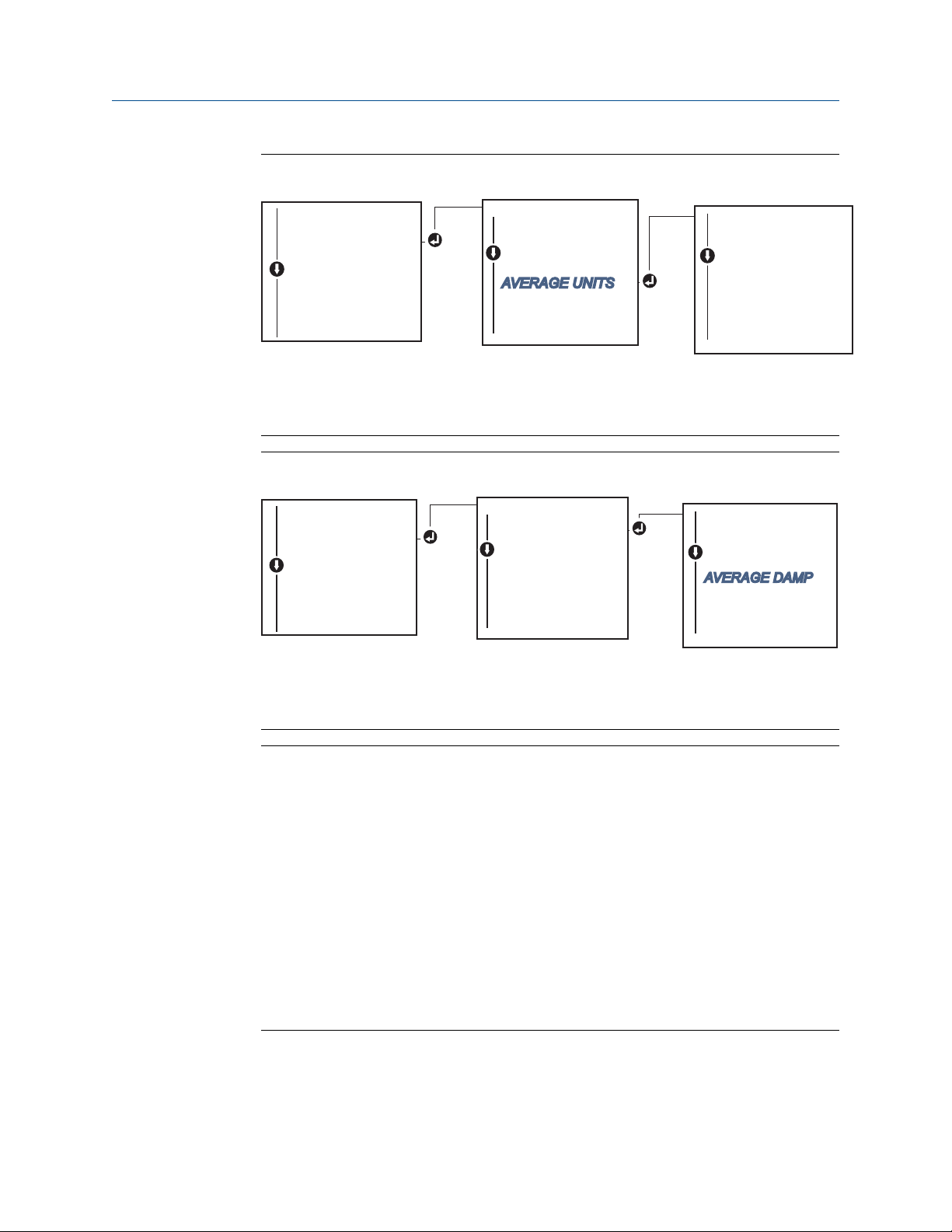
Configure average temperature using LOI
Procedure
• To configure average temperature on the LOI, the units and damping values must be
set separately. Reference Figure 2-10 and Figure 2-11 below for where to find these in
the menu.
Page 29
CHANGE ALL
SENSOR 1 UNITS
SENSOR 2 UNITS*
DIFFRNTL UNITS*
AVERAGE UNITS*
1ST GOOD UNITS**
BACK TO MENU
EXIT MENU
DEG C UNITS
DEG F UNITS
DEG R UNITS
KELVIN UNITS
MV UNITS
OHM UNITS
BACK TO MENU
EXIT MENU
VIEW CONFIG
SENSOR CONFIG
UNITS
RERANGE
LOOP TEST
DISPLAY
EXTENDED MENU
EXIT MENU
CALIBRAT
DAMPING
VARIABLE MAP
TAG
ALARM SAT VALUES
PASSWORD
....
PV DAMP
SENSOR 1 DAMP
SENSOR 2 DAMP*
DIFFRNTL DAMP*
AVERAGE DAMP*
1ST GOOD DAMP**
BACK TO MENU
EXIT MENU
VIEW CONFIG
SENSOR CONFIG
UNITS
RERANGE
LOOP TEST
DISPLAY
EXTENDED MENU
EXIT MENU
Reference Manual Configuration
00809-0200-4728 March 2021
Figure 2-10: Configuring Average Units with LOI
* Available only if option code (S) or (D) is ordered.
** Available only if option codes (S) and (DC) are both ordered, or if option codes (D)
and (DC) are both ordered.
Figure 2-11: Configuring Average Damping with LOI
Emerson.com/Rosemount 29
* Available only if option code (S) or (D) is ordered.
** Available only if option codes (S) and (DC) are both ordered, or if option codes (D)
and (DC) are both ordered.
Note
If Sensor 1 and/or Sensor 2 should fail while PV is configured for average temperature
and Hot Backup™ is not enabled, the transmitter will go into alarm. For this reason, it is
recommended when PV is Sensor Average, that Hot Backup be enabled when dualelement sensors are used, or when two temperature measurements are taken from the
same point in the process. If a sensor failure occurs when Hot Backup is enabled, while
PV is Sensor Average, three scenarios could result:
— If Sensor 1 fails, the average will only be reading from Sensor 2, the working sensor
— If Sensor 2 fails, the average will only be reading from Sensor 1, the working sensor
— If both sensors fail simultaneously, the transmitter will go into alarm and the status
available (via HART®) states that both Sensor 1 and Sensor 2 have failed
In the first two scenarios, the 4–20 mA signal is not disrupted and the status available
to the control system (via HART) specifies which sensor has failed.
Page 30

Configuration Reference Manual
March 2021 00809-0200-4728
2.7.3 Hot Backup configuration
The Hot Backup™ feature configures the transmitter to automatically use Sensor 2 as the
primary sensor if Sensor 1 fails. With Hot Backup enabled, the primary variable (PV) must
either be first good or average. See the Note for details on using Hot Backup when the PV
is set to Sensor Average.
Sensors 1 or 2 can be mapped as the secondary variable (SV), tertiary variable (TV), or
quaternary variable (QV). In the event of a primary variable (Sensor 1) failure, the
transmitter enters Hot Backup mode and Sensor 2 becomes the PV. The 4–20 mA signal is
not disrupted, and a status is available to the control system through HART® that Sensor 1
has failed. An LCD display, if attached, displays the failed sensor status.
While configured to Hot Backup, if Sensor 2 fails but Sensor 1 is still operating properly,
the transmitter continues to report the PV 4–20 mA analog output signal, while a status is
available to the control system through HART that Sensor 2 has failed.
Resetting Hot Backup
In Hot Backup™ mode, if Sensor 1 does fail and Hot Backup is initiated, the transmitter will
not revert back to Sensor 1 to control the 4–20 mA analog output until the Hot Backup
mode is reset by re-enabling through HART®, re-setting it through the LOI or by briefly
powering down the transmitter.
Configure Hot Backup using Field Communicator
The Field Communicator will walk you through a method to correctly configure the
necessary elements of the Hot Backup feature.
From the HOME screen, enter the Fast Key sequence.
Device Dashboard Fast Keys
2, 1, 5
Configure Hot Backup using AMS Device Manager
Procedure
1. Right click on the device and select Configure.
2. In the left navigation pane select Manual Setup.
3. On the Diagnostics Tab find the Hot Backup group box.
4. Choose the button Configure Hot Backup or Reset Hot Backup depending on the
desired function and walk through the guided steps.
5. Select Apply when complete.
Configure Hot Backup using LOI
To configure Hot Backup™ on the LOI, enable the mode and set the PV values. Reference
Figure 2-12 for where to find these in the menu.
30 Emerson.com/Rosemount
Page 31

CALIBRAT
DAMPING
VARIABLE MAP
TAG
ALM SAT VALUES
PASSWORD
SIMULATE
HART REV
HOT BACK CONFIG**
DRIFT ALERT**
....
HOT BACK MODE
HOT BACK PV
HOT BACK RESET
BACK TO MENU
EXIT MENU
VIEW CONFIG
SENSOR CONFIG
UNITS
RERANGE
LOOP TEST
DISPLAY
EXTENDED MENU
EXIT MENU
Reference Manual Configuration
00809-0200-4728 March 2021
Figure 2-12: Configuring Hot Backup with LOI
* Available only if option code (S) or (D) is ordered.
** Available only if option codes (S) and (DC) are both ordered, or if option codes (D) and
(DC) are both ordered.
For information on using Hot Backup with HART Tri-Loop™ see Using the transmitter with
the HART Tri-Loop.
2.7.4
Sensor drift alert configuration
The sensor drift alert command allows the transmitter to set a warning flag (through
HART), or go into analog alarm when the temperature difference between Sensor 1 and
Sensor 2 exceeds a user-defined limit.
This feature is useful when measuring the same process temperature with two sensors,
ideally when using a dual-element sensor. When sensor drift alert mode is enabled, the
user sets the maximum allowable difference, in engineering units, between sensor 1 and
sensor 2. If this maximum difference is exceeded, a sensor drift alert warning flag will be
set.
Though it defaults to WARNING, when configuring the transmitter for sensor drift alert,
the user also has the option of specifying the analog output of the transmitter go into
ALARM when sensor drifting is detected.
Note
Using dual sensor configuration in the Rosemount 644 Transmitter, the transmitter
supports the configuration and simultaneous use of Hot Backup and sensor drift alert. If
one sensor fails, the transmitter switches output to use the remaining good sensor. Should
the difference between the two sensor readings exceed the configured threshold, the AO
will go to alarm indicating the sensor drift condition. The combination of sensor drift alert
and Hot Backup improves sensor diagnostic coverage while maintaining a high level of
availability. Refer to the Rosemount 644 FMEDA report for the impact on safety.
Emerson.com/Rosemount 31
Page 32

CALIBRAT
DAMPING
VARIABLE MAP
TAG
ALM SAT VALUES
PASSWORD
SIMULATE
HART REV
HOT BACK CONFIG**
DRIFT ALERT**
....
DRIFT MODE
DRIFT LIMIT
DRIFT UNITS
DRIFT DAMP
BACK TO MENU
EXIT MENU
VIEW CONFIG
SENSOR CONFIG
UNITS
RERANGE
LOOP TEST
DISPLAY
EXTENDED MENU
EXIT MENU
Configuration Reference Manual
March 2021 00809-0200-4728
Configure sensor drift alert using Field Communicator
The Field Communicator will guide you through a method to correctly configure the
necessary elements of a sensor drift alert feature.
From the HOME screen, enter the Fast Key sequence.
Device Dashboard Fast Keys 2, 1, 6
Configure sensor drift alert using AMS Device Manager
Procedure
1. Right click on the device and select Configure.
2. On the Diagnostics Tab find the Sensor Drift Alert group box.
3. Select to Enable the Mode and fill in the Units, Threshold and Damping values from
the drop downs provided or select the Configure Sensor Drift Alert button and
walk through the guided steps.
4. Select Apply when complete.
Configure sensor drift alert using LOI
To configure sensor drift alert on the LOI, enable the mode, then set the PV, drift limit, and
value for drift alert damping all separately. Reference figure below for where to find these
in the menu.
Figure 2-13: Configuring Sensor Drift Alert with LOI
* Available only if option code (S) or (D) is ordered.
** Available only if option codes (S) and (DC) are both ordered, or if option codes (D) and
(DC) are both ordered.
32 Emerson.com/Rosemount
Note
Enabling the drift alert option to WARNING will set a flag (through the HART
communications) whenever the maximum acceptable difference between Sensor 1 and
Sensor 2 has been exceeded. For the transmitter’s analog signal to go into ALARM when
drift alert is detected, select alarm during the configuration process.
Page 33

Reference Manual Configuration
00809-0200-4728 March 2021
2.8 Configure device outputs
2.8.1 Re-range the transmitter
Re-ranging the transmitter sets the measurement range to the limits of the expected
readings for a certain application. Setting the measurement range to the limits of
expected readings maximizes transmitter performance; the transmitter is most accurate
when operated within the expected temperature range for the application.
The range of expected readings is defined by the Lower Range Value (LRV) and Upper
Range Value (URV). The transmitter range values can be reset as often as necessary to
reflect changing process conditions. For a complete listing of Range and Sensor limits.
Note
The re-range functions should not be confused with the trim functions. Although the rerange function matches a sensor input to a 4–20 mA output, as in conventional
calibration, it does not affect the transmitter’s interpretation of the input.
Select from one of three methods to re-range the transmitter.
Re-range the transmitter using Field Communicator
From the HOME screen, enter the Fast Key sequence.
Lower range value
Device Dashboard Fast Keys 2, 2, 5, 5, 3 2, 2, 5, 5, 2
Upper range value
Re-range the transmitter using AMS Device Manager
Procedure
1. Right click on the device and select Configure.
2. In the left navigation pane select Manual Setup.
3. On the Analog Output Tab find the Primary Variable Configuration group box.
4. Change the Upper Range Value and Lower Range Value to their desired settings.
5. Select Apply when complete.
Emerson.com/Rosemount 33
Page 34

ENTER VALUES
BACK TO MENU
EXIT MENU
LRV
URV
BACK TO MENU
EXIT MENU
VIEW CONFIG
SENSOR CONFIG
UNITS
RERANGE
LOOP TEST
DISPLAY
EXTENDED MENU
EXIT MENU
Configuration Reference Manual
March 2021 00809-0200-4728
Re-range the transmitter using LOI
Reference the image below to find the range value configuration path on the LOI.
Figure 2-14: Re-ranging the Transmitter with LOI
2.8.2 Damping
The damping function changes the response time of the transmitter to smooth variations
in output readings caused by rapid changes in input. Determine the appropriate damping
setting based on the necessary response time, signal stability, and other requirements of
the loop dynamics of the system. The default damping value is 5.0 seconds and can be
reset to any value between 1 and 32 seconds.
34 Emerson.com/Rosemount
The value chosen for damping affects the response time of the transmitter. When set to
zero (disabled), the damping function is off and the transmitter output reacts to changes
in input as quickly as the intermittent sensor algorithm allows. Increasing the damping
value increases transmitter response time.
With damping enabled, if the temperature change is within 0.2 percent of the sensor
limits, the transmitter measures the change in input every 500 milliseconds (for a single
sensor device) and outputs values according to the following relationship:
2T − U
2T + U
+ P
P =
N =
T =
U =
Dampedvalue = N − P x
previous damped value
new sensor value
damping time constant
update rate
At the value to which the damping time constant is set, the transmitter output is at 63
percent of the input change and it continues to approach the input according to the
damping equation above.
For example, as illustrated in Figure 2-15, if the temperature undergoes a step change—
within 0.2 percent of the sensor limits—from 100 to 110 degrees, and the damping is set
to 5.0 seconds, the transmitter calculates and reports a new reading every 500
milliseconds using the damping equation. At 5.0 seconds, the transmitter outputs 106.3
degrees, or 63 percent of the input change, and the output continues to approach the
input curve according to the equation above.
Page 35

Reference Manual Configuration
00809-0200-4728 March 2021
For information regarding the damping function when the input change is greater than
0.2 percent of the sensor limits, refer to Intermittent sensor detection.
Figure 2-15: Change in Input vs. Change in Output with Damping Set to Five Seconds
Damping can be applied to a number of parameters in the Rosemount 644 Transmitter.
Variables that can be damped are:
• Primary Variable (PV)
• Sensor 1
• Sensor 2
• Differential temperature
• Average temperature
• First good temperature
Note
The instructions below only refer to the damping of the Primary Variable (PV).
Set damping value using Field Communicator
From the HOME screen, enter the Fast Key sequence.
Device Dashboard Fast Keys 2, 2, 1, 5 2, 2, 1, 6
HART 5 HART 7
Set damping value using AMS Device Manager
Procedure
1. Right click on the device and select Configure.
2. In the left navigation pane select Manual Setup.
3. On the Sensor 1 Tab find the Setup group box.
4. Change the Damping Value to the desired setting.
5. Select Apply when complete.
Emerson.com/Rosemount 35
Page 36

Configuration Reference Manual
March 2021 00809-0200-4728
Set damping value using LOI
Reference the figure below to find the damping configuration path on the LOI.
Figure 2-16: Set damping value using LOI
2.8.3 Configure alarm and saturation levels
In normal operation, the transmitter will drive the output in response to measurements
between the lower to upper saturation points. If the temperature goes outside the sensor
limits, or if the output would be beyond the saturation points, the output will be limited to
the associated saturation point.
The transmitter automatically and continuously performs self-diagnostic routines. If the
self-diagnostic routines detect a failure, the transmitter drives the output to configured
alarm value based on the position of the alarm switch. The Alarm and Saturation settings
allow the alarm settings (Hi or Low) and saturation values to be viewed and changed.
Failure mode alarm and saturation levels can be configured using a Field Communicator,
AMS Device Manager, and the LOI. The following limitations exist for custom levels:
• The low alarm value must be less than the Low Saturation level.
• The high alarm value must be higher than the High Saturation level.
• Alarm and Saturation levels must be separated by at least 0.1 mA
The configuration tool will provide an error message if the configuration rule is violated.
See table below for the common alarm and saturation levels.
Table 2-4: Rosemount Alarm and Saturation Values
Units - mA Min Max Rosemount NAMUR
High alarm 21 23 21.75 21.0
Low alarm
High saturation 20.5 20.9
Low saturation
(1) Requires 0.1 mA gap between low alarm and low saturation values.
(2) Rail mount transmitters have a high saturation max of 0.1 mA less than the high alarm setting,
(3) Rail mount transmitters have a low saturation min of 0.1 mA greater than the low alarm setting,
(1)
(1)
with a max value of 0.1 mA less than the high alarm max.
with a minimum of 0.1 mA greater than the low alarm min.
3.5 3.75 3.75 3.6
(3)
3.7
3.9 3.9 3.8
(2)
20.5 20.5
36 Emerson.com/Rosemount
Page 37

CALIBRAT
DAMPING
VARIABLE MAP
TAG
ALM SAT VALUES
PASSWORD
SIMULATE
HART REV
HOT BACK CONFIG**
DRIFT ALERT**
....
ROSEMNT VALUES
NAMUR VALUES
OTHER VALUES
BACK TO MENU
EXIT MENU
VIEW CONFIG
SENSOR CONFIG
UNITS
RERANGE
LOOP TEST
DISPLAY
EXTENDED MENU
EXIT MENU
Reference Manual Configuration
00809-0200-4728 March 2021
Note
Transmitters set to HART multidrop mode send all saturation and alarm information
digitally; saturation and alarm conditions will not affect the analog output.
Configure alarm and saturation levels using Field Communicator
From the HOME screen, enter the Fast Key sequence.
Device Dashboard Fast Keys 2, 2, 5, 6
Configure alarm and saturation levels using AMS Device Manager
Procedure
1. Right click on the device and select Configure.
2. In the left navigation pane select Manual Setup.
3. On the Analog Output Tab find the Alarm and Saturation Levels group box.
4. Enter the High Alarm, High Saturation, Low Saturation and Low Alarm levels to the
desired vales.
5. Select Apply when complete.
Configure alarm and saturation levels using LOI
Reference the Figure 2-17 below to find the alarm and saturation value configuration path
on the LOI.
Figure 2-17: Configuring Alarm and Saturation Values with LOI
* Available only if option code (S) or (D) is ordered.
** Available only if option codes (S) and (DC) are both ordered, or if option codes (D) and
(DC) are both ordered.
Emerson.com/Rosemount 37
Page 38

Configuration Reference Manual
March 2021 00809-0200-4728
2.8.4 Configuring the LCD display
The LCD display configuration command allows customization of the LCD display to suit
application requirements. The LCD display will alternate between the selected items with
each item displaying for a three seconds interval.
• Sensor 1
• Sensor 2
• Analog output
• Primary variable
• Average temperature
• First good temperature
• Differential temperature
• Percent of range
• Terminal temperature
• Min and max 1
• Min and max 2
• Min and max 3
• Min and max 4
Reference Figure 2-18 to view the differences between the LCD display and LOI options
available with the transmitter.
38 Emerson.com/Rosemount
Page 39

Reference Manual Configuration
00809-0200-4728 March 2021
Figure 2-18: LOI and LCD Display
LCD display LOI
Configure the LCD display using Field Communicator
From the HOME screen, enter the Fast Key sequence.
Device Dashboard Fast Keys
2, 1, 4
Configure the LCD display using AMS Device Manager
Procedure
1. Right click on the device and select Configure.
2. In the left navigation pane select Manual Setup.
Note
On the Display tab there will be a group box with all available variables that can be
displayed.
3. Check and uncheck the desired display variables, with a checked box indicating that
the variable will be displayed.
4. Select Apply when complete.
Emerson.com/Rosemount 39
Page 40

SENSOR 1
SENSOR 2*
ANALOG
PV
AVG*
1ST GOOD*
DIFF*
% RANGE
TERM
MNMAX1*
MNMAX2*
MNMAX3*
MNMAX4*
BACK TO MENU
EXIT MENU
VIEW CONFIG
SENSOR CONFIG
UNITS
RERANGE
LOOP TEST
DISPLAY
EXTENDED MENU
EXIT MENU
Configuration Reference Manual
March 2021 00809-0200-4728
Configure the LCD display using LOI
Reference Figure 2-19 to find the LCD display value configuration path on the LOI.
Figure 2-19: Configuring the LCD Display using LOI
2.9 Inputting device information
2.9.1
40 Emerson.com/Rosemount
*Available only if option code (S) or (D) is ordered.
Access the transmitter information variables online using the Field Communicator or other
suitable communications device. The following is a list of transmitter information
variables, including device identifiers, factory-set configuration variables, and other
information.
Tag, Date, Descriptor, and Message
The Tag, Date, Descriptor, and Message are parameters that provide transmitter
identification in large installations.
The Tag variable is the easiest way to identify and distinguish between different
transmitters in multi-transmitter environments. It is used to label transmitters
electronically according to the requirements of the application. The defined Tag is
automatically displayed when a HART®-based communicator establishes contact with the
transmitter at power-up. The Tag is up to eight characters and the Long Tag (a parameter
introduced with the HART 6 and 7 protocol) was extended to 32 characters long. Neither
parameter has any impact on the primary variable readings of the transmitter, it is only for
information.
The Date is a user-defined variable that provides a place to save the date of the last
revision of configuration information. It has no impact on the operation of the transmitter
or the HART-based communicator.
The Descriptor variable provides a longer user-defined electronic label to assist with more
specific transmitter identification than is available with tag. The Descriptor may be up to
Page 41

CALIBRAT
DAMPING
VARIABLE MAP
TAG
ALM SAT VALUES
PASSWORD
....
VIEW CONFIG
SENSOR CONFIG
UNITS
RERANGE
LOOP TEST
DISPLAY
EXTENDED MENU
EXIT MENU
Reference Manual Configuration
00809-0200-4728 March 2021
16 characters long and has no impact on the operation of the transmitter or the HARTbased communicator.
The Message variable provides the most specific user-defined means for identifying
individual transmitters in multi-transmitter environments. It allows for 32 characters of
information and is stored with the other configuration data. The Message variable has no
impact on the operation of the transmitter or the HART-based communicator.
Input device information using Field Communicator
From the HOME screen, enter the Fast Key sequence.
Device Dashboard Fast Keys 1, 8
Input device information using AMS Device Manager
Procedure
1. Right click on the device and select Configure.
2. In the left navigation pane select Manual Setup.
3. On the Device Tab there will be a group box called identification. Enter the desired
characters in the Tag, Date, Descriptor, and Message fields
4. Select Apply when complete.
Emerson.com/Rosemount 41
Input device information using LOI
Reference Figure 2-20 to find the tag configuration path in the LOI.
Figure 2-20: Configuring the Tag with LOI
Page 42

Configuration Reference Manual
March 2021 00809-0200-4728
2.10 Configure measurement filtering
2.10.1 50/60 Hz filter
The 50/60 Hz Filter (also known as Line Voltage Filter or AC Power Filter) function sets the
transmitter electronic filter to reject the frequency of the AC power supply in the plant.
The 60 or 50 Hz mode can be chosen. The factory default for this setting is 50 Hz.
Configure measurement filtering using Field Communicator
From the HOME screen, enter the Fast Key sequence.
2.10.2
Device Dashboard Fast Keys
2, 2, 7, 4, 1
Configure measurement filtering using AMS Device Manager
Procedure
1. Right click on the device and select Configure.
2. In the left navigation pane select Manual Setup.
3. On the Device Tab there will be a group box called Noise Rejection. In the AC
Power Filter box, select from the drop down menu.
4. Select Apply when complete.
Resetting the device
Processor Reset function resets the electronics without actually powering down the unit. It
does not return the transmitter to the original factory configuration.
Reset the device using a Field Communicator
From the HOME screen, enter the Fast Key sequence.
Device Dashboard Fast Keys
3, 4, 6, 1
Reset the device using AMS Device Manager
Procedure
1. Right click on the device and select Service Tools.
2. In the left navigation pane select Maintenance.
3. On the Reset/Restore tab select the Processor Reset button.
4. Select Apply when complete.
42 Emerson.com/Rosemount
Page 43

Reference Manual Configuration
00809-0200-4728 March 2021
2.10.3 Intermittent sensor detection
The intermittent sensor detection feature (also known as the transient filter) is designed to
guard against erratic process temperature readings caused by intermittent open sensor
conditions. An intermittent sensor condition is an open sensor condition that lasts less
than one update. By default, the transmitter is shipped with the intermittent sensor
detection feature switched ON and the threshold value set at 0.2 percent of sensor limits.
The intermittent sensor detect feature can be switched ON or OFF and the threshold value
can be changed to any value between 0 and 100 percent of the sensor limits with a Field
Communicator.
When the intermittent sensor detection feature is switched ON, the transmitter can
eliminate the output pulse caused by intermittent open sensor conditions. Process
temperature changes (T) within the threshold value will be tracked normally by the
transmitter’s output. A (T) greater than the threshold value will activate the intermittent
sensor algorithm. True open sensor conditions will cause the transmitter to go into alarm.
The threshold value of the transmitter should be set at a level that allows the normal range
of process temperature fluctuations; too high and the algorithm will not be able to filter
out intermittent conditions; too low and the algorithm will be activated unnecessarily. The
default threshold value is 0.2 percent of the sensor limits.
When the intermittent sensor detection feature is switched OFF, the transmitter tracks all
process temperature changes, even from an intermittent sensor. (The transmitter behaves
as though the threshold value had been set at 100 percent.) The output delay due to the
intermittent sensor algorithm will be eliminated.
Configure intermittent sensor detect using a Field Communicator
The following steps indicate how to turn the intermittent sensor detect (or transient filter)
feature ON or OFF. When the transmitter is connected to a Field Communicator, use the
Fast Key sequence and choose ON (normal setting) or OFF.
From the HOME screen, enter the Fast Key sequence.
Device Dashboard Fast Keys
The threshold value can be changed from the default value of 0.2 percent. Turning the
Intermittent Sensor Detect feature OFF or leaving it ON and increasing the threshold value
above the default does not affect the time needed for the transmitter to output the
correct alarm signal after detecting a true open sensor condition. However, the
transmitter may briefly output a false temperature reading for up to one update in either
direction up to the threshold value (100 percent of sensor limits if Intermittent Sensor
Detect is OFF). Unless a rapid response rate is necessary, the suggested setting is ON with
0.2 percent threshold.
2, 2, 7, 4, 2
Configure intermittent sensor detect using AMS Device Manager
Procedure
1. Right click on the device and select Configure.
Emerson.com/Rosemount 43
Page 44

Configuration Reference Manual
March 2021 00809-0200-4728
2. In the left navigation pane select Manual Setup.
Note
On the Device Tab there will be a group box called Noise Rejection, in the box
Transient Filter Threshold, enter the desired percent.
3. Select Apply when complete.
2.10.4 Open sensor hold off
The open sensor hold off option, at the normal setting, enables the Rosemount 644
Transmitter to be more robust under heavy EMI conditions. This is accomplished by the
software having the transmitter perform additional verification of the open sensor status
prior to activating the transmitter alarm. If the additional verification shows that the open
sensor condition is not valid, the transmitter will not go into alarm.
For users of the Rosemount 644 Transmitter that desire a more vigorous open sensor
detection, the open sensor hold off option can be changed to a fast setting where the
transmitter will report an open sensor condition without additional verification of whether
or not the open condition is valid.
Note
In high noise environments, normal mode is recommended.
Configure open sensor hold off using a Field Communicator
From the HOME screen, enter the Fast Key sequence.
Device Dashboard Fast Keys
Configure open sensor hold off using AMS Device Manager
Procedure
1. Right click on the device and select Configure.
2. In the left navigation pane select Manual Setup.
3. On the Device Tab there will be a group box called Open Sensor Hold Off. Change
the Mode to either Normal or Fast.
4. Select Apply when complete.
2.11 Diagnostics and service
2.11.1 Perform a loop test
2, 2, 7, 3
The analog loop test verifies the output of the transmitter, the integrity of the loop, and
the operations of any recorders or similar devices installed in the loop. To initiate a loop
test, follow the steps below.
The host system may provide a current measurement for the 4–20 mA HART® output. If
not, connect a reference meter to the transmitter by either connecting the meter to the
44 Emerson.com/Rosemount
Page 45

SET 4 MA
SET 20 MA
SET CUSTOM
END LOOP TEST
BACK TO MENU
EXIT MENU
VIEW CONFIG
SENSOR CONFIG
UNITS
RERANGE
LOOP TEST
DISPLAY
EXTENDED MENU
EXIT MENU
Reference Manual Configuration
00809-0200-4728 March 2021
test terminals on the terminal block, or shunting transmitter power through the meter at
some point in the loop.
Perform a loop test using a Field Communicator
From the HOME screen, enter the Fast Key sequence.
Device Dashboard Fast Keys 3, 5, 1
Perform a loop test using AMS Device Manager
Procedure
1. Right click on the device and select Service Tools.
2. In the left navigation pane select Simulate.
3. On the Simulate Tab find the Perform Loop Test button in the Analog Output
Verification group box.
4. Follow the guided instructions and select Apply when complete.
2.11.2
Perform a loop test using LOI
Reference the Figure 2-21 to find the path to the loop test in the LOI menu.
Figure 2-21: Performing a Loop Test with the LOI
Simulate digital signal (digital loop test)
The simulate digital signal function adds to the analog loop test by confirming the HART
output values are outputting correctly. Digital loop test is only available in HART Revision 7
mode.
Simulate a digital signal using a Field Communicator
From the HOME screen, enter the Fast Key sequence.
Emerson.com/Rosemount 45
Device Dashboard Fast Keys
3, 5, 2
Page 46

CALIBRAT
DAMPING
VARIABLE MAP
TAG
ALM SAT VALUES
PASSWORD
SIMULATE
HART REV
....
SIMULATE SNSR 1
SIMULATE SNSR 2*
END SIMUL
BACK TO MENU
EXIT MENU
VIEW CONFIG
SENSOR CONFIG
UNITS
RERANGE
LOOP TEST
DISPLAY
EXTENDED MENU
EXIT MENU
Configuration Reference Manual
March 2021 00809-0200-4728
Simulate a digital signal using AMS Device Manager
Procedure
1. Right click on the device and select Service Tools.
2. In the left navigation window select Simulate.
3. In the group box labeled Device Variables select the variable to simulate.
a) Sensor 1 Temperature
b) Sensor 2 Temperature (only available with option S or D)
4. Follow the screen prompts to simulate selected digital value.
Simulate a digital signal using LOI
Reference the Figure 2-22 to find the path to the simulate digital signal in the LOI menu.
Figure 2-22: Simulating the Digital Signal with LOI
2.11.3
46 Emerson.com/Rosemount
*Available only if option code (S) or (D) is ordered.
Thermocouple degradation diagnostic
Thermocouple degradation diagnostic acts as a gauge of the general health of the
thermocouple and is indicative of any major changes in the status of the thermocouple or
the thermocouple loop. The transmitter monitors the resistance of the thermocouple loop
to detect drift conditions or wiring condition changes. The transmitter uses a baseline and
threshold Trigger value and reports the suspected status of the thermocouple based off
the difference between these values. This feature is not intended to be a precise
measurement of thermocouple status, but is a general indicator of thermocouple and
thermocouple loop health.
Thermocouple diagnostic must be Enabled as well as connected and configured to read a
thermocouple type sensor. Once the diagnostic has been activated, a baseline resistance
value is calculated. Then a Trigger threshold must be selected, which can be two, three, or
four times the baseline resistance, or the default of 5000 ohms. If the thermocouple loop
resistance reaches the Trigger Level, a maintenance alert is generated.
Page 47

CALIBRAT
DAMPING
VARIABLE MAP
TAG
ALM SAT VALUES
PASSWORD
SIMULATE
HART REV
HOT BACK CONFIG*
DRIFT ALERT*
TC DIAG CONFIG
MIN MAX TRACK
BACK TO MENU
EXIT MENU
CONFIG SNSR 1
CONFIG SNSR 2*
BACK TO MENU
EXIT MENU
VIEW CONFIG
SENSOR CONFIG
UNITS
RERANGE
LOOP TEST
DISPLAY
EXTENDED MENU
EXIT MENU
SENSOR 1 MODE
TRIGGER CONFIG
TRIGGER VIEW
SNSR OHM VIEW
BASELINE RE-SET
BASELINE VIEW
BACK TO MENU
EXIT MENU
Reference Manual Configuration
00809-0200-4728 March 2021
CAUTION
The thermocouple degradation diagnostic monitors the health of the entire thermocouple
loop, including wiring, terminations, junctions, and the sensor itself. Therefore, it is
imperative that the diagnostic baseline resistance be measured with the sensor fully
installed and wired in the process, and not on the bench.
Note
The thermocouple resistance algorithm does not calculate resistance values while the
active calibrator mode is enabled.
Perform thermocouple degradation diagnostic using a Field Communicator
From the HOME screen, enter the Fast Key sequence.
Device Dashboard Fast Keys
2, 2, 4, 3, 4
Perform thermocouple degradation diagnostic using AMS Device Manager
Procedure
1. Right click on the device and select Configure.
2. In the left navigation window select Manual Setup.
3. On the Diagnostics tab, there is a group box labeled Sensor and Process
Diagnostics; select the button for Configure Thermocouple Diagnostic.
4. Follow the screen prompts to Enable and set the values for the diagnostic.
See AMS terms.
Perform thermocouple degradation diagnostic using LOI
Reference the Figure 2-23 to find the path to the thermocouple diagnostic in the LOI
menu.
Figure 2-23: Configuring T/C Diagnostic with LOI
Emerson.com/Rosemount 47
* Available only if option code (S) or (D) is ordered.
Page 48

Configuration Reference Manual
March 2021 00809-0200-4728
2.11.4 Minimum/maximum tracking diagnostic
Minimum and maximum temperature tracking (min/max tracking) when enabled records
minimum and maximum temperatures with date and time stamps on Rosemount 644
HART Head Mount and Field Mount Temperature Transmitters. This feature records values
for Sensor 1, Sensor 2, Differential, Average, First Good, and Terminal temperatures.
Min/Max Tracking only records temperature maximum and minimum obtained since the
last reset, and is not a logging function.
To track maximum and minimum temperatures, Min/Max Tracking must be enabled using
a Field Communicator, AMS Device Manager, LOI, or other communicator. While enabled,
this feature allows for a reset of information at any time, and all variables can be reset
simultaneously. Additionally, each of the individual parameter’s minimum and maximum
values may be reset individually. Once a particular field has been reset, the previous values
are overwritten.
Track minimum and maximum temperatures using a Field Communicator
From the HOME screen, enter the Fast Key sequence.
Device Dashboard Fast Keys
2, 2, 4, 3, 5
Track minimum and maximum temperatures using AMS Device Manager
Procedure
1. Right click on the device and select Configure.
2. In the left navigation window select Manual Setup.
3. On the Diagnostics tab, there is a group box labeled Sensor and Process
Diagnostics; select the button for Configure Min/Max Tracking.
4. Follow the screen prompts to Enable and configure the settings for the diagnostic.
48 Emerson.com/Rosemount
Page 49

CALIBRAT
DAMPING
VARIABLE MAP
TAG
ALM SAT VALUES
PASSWORD
SIMULATE
HART REV
HOT BACK CONFIG*
DRIFT ALERT*
TC DIAG CONFIG
MIN MAX TRACK
BACK TO MENU
EXIT MENU
VIEW CONFIG
SENSOR CONFIG
UNITS
RERANGE
LOOP TEST
DISPLAY
EXTENDED MENU
EXIT MENU
MIN-MAX MODE
PARAM CONFIG
VIEW VALUES
RESET VALUES
BACK TO MENU
EXIT MENU
Reference Manual Configuration
00809-0200-4728 March 2021
Track minimum and maximum temperatures using LOI
Reference the Figure 2-24 to find the path to configure min/max in the LOI menu
Figure 2-24: Configuring Min/Max Tracking with LOI
* Available only if option code (S) or (D) is ordered.
2.12 Establishing multi-drop communication
Multi-dropping refers to the connection of several transmitters to a single
communications transmission line. Communication between the host and the
transmitters takes place digitally with the analog output of the transmitters deactivated.
Many Rosemount transmitters can be multi-dropped. With the Field Communications
protocol, up to 15 transmitters can be connected on a single twisted pair of wires or over
leased phone lines.
A Field Communicator can test, configure, and format a multi-dropped Transmitter in the
same way as in a standard point-to-point installation. The application of a multidrop
installation requires consideration of the update rate necessary from each transmitter, the
combination of transmitter models, and the length of the transmission line. Each
transmitter is identified by a unique address (1–15) and responds to the commands
defined in the HART protocol. A Field Communicator can test, configure, and format a
multidropped transmitter the same as in a standard point-to-point installation.
Note
Multi-drop is not suitable for safety-certified applications and installations.
Emerson.com/Rosemount 49
Page 50

A
B
C
D
E
F
G
H
Configuration Reference Manual
March 2021 00809-0200-4728
Figure 2-25: Typical Multi-dropped Network
A. Power supply
B. Power supply impedance
C. 250 Ω
D. Field Communicator
E. Computer or DCS
F. HART interface
G. 4–20 mA
H. Transmitter
Note
Rosemount 644 Transmitters are set to address 0 at the factory, allowing them to operate
in the standard point-to-point manner with a 4–20 mA output signal. To activate
multidrop communication, the transmitter address must be changed to a number
between 1 and 15. This change deactivates the 4–20 mA analog output, sending it to 4
mA. The failure mode current also is disabled.
2.12.1
Changing a transmitter address
To activate multi drop communication, the transmitter poll address must be assigned a
number from 1–15 for HART Revision 5, and 1–63 for HART Revision 7. Each transmitter in
a multi dropped loop must have a unique poll address.
50 Emerson.com/Rosemount
Page 51

Reference Manual Configuration
00809-0200-4728 March 2021
Change transmitter address using a Field Communicator
From the HOME screen, enter the Fast Key sequence.
Device Dashboard Fast Keys 1, 2, 1
Change transmitter address using AMS Device Manager
Procedure
1. Right click on the device and select Configuration Properties from the menu.
2. In HART Revision 5 mode:
a) In the HART tab, enter poll address into the Polling Address box, select
Apply.
3. In HART Revision 7 mode:
a) In the HART tab, select the Change Polling Address button.
2.13 Using the transmitter with the HART Tri-Loop
To prepare the transmitter with dual-sensor option for use with a Rosemount 333 HART
Tri-Loop, the transmitter must be configured to Burst Mode and the process variable
output order must be set. In Burst Mode, the transmitter provides digital information for
the four process variables to the HART Tri-Loop. The HART Tri-Loop divides the signal into
separate 4–20 mA loops for up to three of the following choices:
• Primary Variable (PV)
• Secondary Variable (SV)
• Tertiary Variable (TV)
• Quaternary Variable (QV)
When using the transmitter with dual-sensor option in conjunction with the HART TriLoop, consider the configuration of the differential, average, first good temperatures,
Sensor Drift Alert, and Hot Backup features (if applicable).
Note
The procedures are to be used when the sensors and transmitters are connected,
powered, and functioning properly. Also, Field Communicator must be connected and
communicating to the transmitter control loop. For communicator usage instructions, see
Verify configuration using the Field Communicator.
®
Emerson.com/Rosemount 51
Page 52

Configuration Reference Manual
March 2021 00809-0200-4728
2.13.1 Set the transmitter to burst mode
To set the transmitter to burst mode, follow the steps below with the Fast Key sequence.
Set the transmitter to burst mode using a Field Communicator
From the HOME screen, enter the Fast Key sequence.
HART 5 HART 7
Device Dashboard Fast Keys 2, 2, 8, 4 2, 2, 8, 5
Set the transmitter to burst mode using AMS Device Manager
Procedure
1. Right click on the device and select Configure.
2. In the left navigation window select Manual Setup.
3. On the HART tab find the Burst Mode Configuration group box and fill in the
necessary content.
4. Select Apply when complete.
2.13.2
Set process variable output order
To set the process variable output order, follow the steps in one of the methods outlined
in Mapping the HART variables.
Note
Take careful note of the process variable output order. The HART® Tri-Loop must be
configured to read the variables in the same order.
Special considerations
To initiate operation between a transmitter with dual-sensor option and the HART® TriLoop, consider the configuration of both the differential, average and first good
temperatures, sensor drift alert, and Hot Backup features (if applicable).
Differential temperature measurement
To enable the differential temperature measurement feature of a dual-sensor operating in
conjunction with the HART® Tri-Loop, adjust the range end points of the corresponding
channel on the HART Tri-Loop to include zero. For example, if the secondary variable is to
report the differential temperature, configure the transmitter accordingly (see Mapping
the HART variables) and adjust the corresponding channel of the HART Tri-Loop so one
range end point is negative and the other is positive.
Hot Backup
To enable the Hot Backup feature of a transmitter with dual-sensor option operating in
conjunction with the HART Tri-Loop, ensure that the output units of the sensors are the
52 Emerson.com/Rosemount
Page 53

Reference Manual Configuration
00809-0200-4728 March 2021
same as the units of the HART Tri-Loop. Use any combination of RTDs or thermocouples as
long as the units of both match the units of the HART Tri-Loop.
Using the Tri-Loop to detect sensor drift alert
The dual-sensor transmitter sets a failure flag (through HART) whenever a sensor failure
occurs. If an analog warning is required, the HART Tri-Loop can be configured to produce
an analog signal that can be interpreted by the control system as a sensor failure.
Use these steps to set up the HART Tri-Loop to transmit sensor failure alerts.
Procedure
1. Configure the dual-sensor transmitter variable map as shown:
Variable Mapping
PV Sensor 1 or sensor average
SV Sensor 2
TV Differential temperature
QV As desired
2. Configure Channel 1 of the HART Tri-Loop as TV (differential temperature). If either
sensor should fail, the differential temperature output will be +9999 or –9999 (high
or low saturation), depending on the position of the Failure Mode Switch (see
Setting the alarm switch).
3. Select temperature units for Channel 1 that match the differential temperature
units of the transmitter.
4. Specify a range for the TV such as -148 to 212 °F (-100 to 100 °C). If the range is
large, then a sensor drift of a few degrees will represent only a small percent of
range. If Sensor 1 or Sensor 2 fails, the TV will be +9999 (high saturation) or –9999
(low saturation). In this example, zero is the midpoint of the TV range. If a ΔT of zero
is set as the lower range limit (4 mA), then the output could saturate low if the
reading from Sensor 2 exceeds the reading from Sensor 1. By placing a zero in the
middle of the range, the output will normally stay near 12 mA, and the problem will
be avoided.
5. Configure the DCS so that TV < –148 °F (–100 °C) or TV > 212 °F (100 °C) indicates a
sensor failure and, for example, TV ≤ 26.6 °F (–3 °C) or TV ≥ 37.4 °F (3 °C) indicates a
drift alert. See Figure 2-26.
Emerson.com/Rosemount 53
Page 54

Configuration Reference Manual
March 2021 00809-0200-4728
Figure 2-26: Tracking Sensor Drift and Sensor Failure with Differential
Temperature
2.14 Transmitter security
2.14.1 Available security options
There are three security methods to utilize with the transmitter.
• Software security switch (write protect)
• HART lock
• LOI password
The write protect feature allows you to protect the transmitter data from accidental or
unwarranted configuration changes. To enable the write protect feature, perform the
following procedures.
Configure transmitter security using a Field Communicator
From the HOME screen, enter the Fast Key sequence.
Write Protect
HART Lock 2, 2, 9, 2
LOI Password 2, 2, 9, 3
2, 2, 9, 1
54 Emerson.com/Rosemount
Page 55

Reference Manual Configuration
00809-0200-4728 March 2021
Configure transmitter security using AMS Device Manager
Procedure
1. Right click on the device and select the Configure menu.
2. In the left navigation pane select Manual Setup then select the Security tab.
• All three parameters can be configured from this screen.
3. Select Apply when complete.
Emerson.com/Rosemount 55
Page 56

Configuration Reference Manual
March 2021 00809-0200-4728
56 Emerson.com/Rosemount
Page 57

Reference Manual Hardware Installation
00809-0200-4728 March 2021
3 Hardware Installation
Note
Each transmitter is marked with a tag indicating the approvals. Install the transmitter
according to all applicable installation codes, and approval and installation drawings (see
Product Data Sheet). Verify the operating atmosphere of the transmitter is consistent with
the hazardous location certifications. Once a device labeled with multiple approval types is
installed, it should not be reinstalled using any of the other labeled approval types. To
ensure this, the approval label should be permanently marked to distinguish the approval
type(s) used.
3.1 Overview
The information in this section covers installation considerations for the Rosemount 644
Temperature Transmitter with HART® Protocol. A Quick Start Guide is shipped with every
transmitter to describe recommended mounting and wiring procedures for initial
installation. Dimensional drawings for transmitter mounting configurations are included in
the Product Data Sheet.
3.2 Safety messages
Instructions and procedures in this section may require special precautions to ensure the
safety of the personnel performing the operations. Refer to the following safety messages
before performing an operation preceded by this symbol.
WARNING
Follow instruction
Failure to follow these installation guidelines could result in death or serious injury.
Ensure only qualified personnel perform the installation.
Explosion
Explosions could result in death or serious injury.
Do not remove the connection head cover in explosive atmospheres when the circuit is
live.
Before connecting a handheld communicator in an explosive atmosphere, ensure that
the instruments in the loop are installed in accordance with intrinsically safe or nonincendive field wiring practices.
Verify that the operating atmosphere of the transmitter is consistent with the
appropriate hazardous locations certifications.
All connection head covers must be fully engaged to meet explosion-proof
requirements.
Emerson.com/Rosemount 57
Page 58

Hardware Installation Reference Manual
March 2021 00809-0200-4728
WARNING
Process leaks
Process leaks could result in death or serious injury.
Do not remove the thermowell while in operation.
Install and tighten thermowells and sensors before applying pressure.
Electric shock
Electrical shock could cause death or serious injury.
Use extreme caution when making contact with the leads and terminals.
Physical access
Unauthorized personnel may potentially cause significant damage to and/or
misconfiguration of end users’ equipment. This could be intentional or unintentional and
needs to be protected against.
Physical security is an important part of any security program and fundamental to
protecting your system. Restrict physical access by unauthorized personnel to protect end
users’ assets. This is true for all systems used within the facility.
3.3 Considerations
3.3.1 General
Electrical temperature sensors such as RTDs and thermocouples produce low-level signals
proportional to their sensed temperature. The transmitter converts the low-level sensor
signal to a standard 4–20 mA dc or digital HART® signal that is relatively insensitive to lead
length and electrical noise. This signal is then transmitted to the control room via two
wires.
3.3.2
3.3.3
Commissioning
The transmitter can be commissioned before or after installation. It may be useful to
commission it on the bench, before installation, to ensure proper operation and to
become familiar with its functionality. Ensure the instruments in the loop are installed in
accordance with intrinsically safe, or non-incendive field wiring practices.
Installation
Measurement accuracy depends upon proper installation of the transmitter. Mount the
transmitter close to the process and use minimum wiring to achieve best accuracy. Keep
in mind the need for easy access, personnel safety, practical field calibration, and a
suitable transmitter environment. Install the transmitter to minimize vibration, shock, and
temperature fluctuation.
58 Emerson.com/Rosemount
Page 59

Reference Manual Hardware Installation
00809-0200-4728 March 2021
3.3.4 Mechanical
Location
When choosing an installation location and position, take into account the need for access
to the transmitter.
Special mounting
Special mounting hardware is available for mounting a Rosemount 644 Head Mount
Transmitter to a DIN rail or assembling a new Rosemount 644 Head Mount to an existing
threaded sensor connection head (former option code L1).
3.3.5 Electrical
Proper electrical installation is necessary to prevent errors due to sensor lead resistance
and electrical noise. For best results, shielded cable should be used in electrically noisy
environments.
Make wiring connections through the cable entry in the side of the housing. Provide
adequate clearance for cover removal.
3.3.6
Environmental
The transmitter electronics module is permanently sealed within a plastic enclosure,
resisting moisture and corrosive damage. Verify that the operating atmosphere of the
transmitter is consistent with the appropriate hazardous locations certifications.
Temperature effects
The transmitter will operate within specifications for ambient temperatures between –40
and 185 °F (–40 °C and 85 °C). Heat from the process is transferred from the thermowell to
the transmitter housing. If the expected process temperature is near or beyond
specification limits, consider the use of additional thermowell lagging, an extension
nipple, or a remote mounting configuration to isolate the transmitter from the process.
Figure 3-1 provides an example of the relationship between transmitter housing
temperature rise and extension length.
Emerson.com/Rosemount 59
Page 60

60 (108)
50 (90)
40 (72)
30 (54)
20 (36)
10 (18)
0
3 4 5 6 7 8 9
815 C (1500 F)
Oven Temperature
540 C (1000 F)
Oven Temperature
250 C (482 F)
Oven Temperature
Housing Temperature Rise Above Ambient C ( F)
Extension Length (in.)
3.6
22
Hardware Installation Reference Manual
March 2021 00809-0200-4728
Figure 3-1: Head Mount Transmitter Connection Head Temperature Rise vs.
Extension Length
Example
The maximum permissible housing temperature rise (T) can be calculated by subtracting
the maximum ambient temperature (A) from the transmitter’s ambient temperature
specification limit (S). For instance, if A = 40 °C.
T = S - A T = 85 °C – 40 °C T = 45 °C
For a process temperature of 540 °C (1004 °F), an extension length of 3.6-in. (91.4 mm)
yields a housing temperature rise (R) of 22 °C (72 °F), providing a safety margin of 23 °C
(73 °F). A 6.0-in. (152.4 mm) extension length (R = 10 °C [50 °F]) offers a higher safety
margin (35 °C [95 °F]) and reduces temperature-effect errors but would probably require
extra transmitter support. Gauge the requirements for individual applications along this
scale. If a thermowell with lagging is used, the extension length may be reduced by the
length of the lagging.
60 Emerson.com/Rosemount
Page 61

Reference Manual Hardware Installation
00809-0200-4728 March 2021
3.4 Installation procedures
Figure 3-2: Installation Flowchart
3.4.1 Setting the alarm switch
Verify the alarm switch is set to the desired position before putting the device into
operation to ensure correct function in the instance of a failure.
Setting the alarm switch without an LCD display
Procedure
1. Set the loop to manual (if applicable) and disconnect the power.
2. Remove the housing cover.
3. Set the physical hardware alarm switch to the desired position. H indicates High, L
indicates Low. Then reattach the housing cover. See Figure 3-3 for alarm switch
location.
Emerson.com/Rosemount 61
Page 62

Hardware Installation Reference Manual
March 2021 00809-0200-4728
4. Apply power and set the loop to automatic control.
Figure 3-3: Failure Switch Location
Transmitter Field mount transmitter
A. Alarm switch
Note
If using an LCD Display or LOI, first remove the display by detaching it from the top
of the device, set the switch to the desired position and reattach the display. See
Figure 3-4 for proper display orientation.
Figure 3-4: Display Connection
Transmitter Field mount transmitter
62 Emerson.com/Rosemount
Page 63

A
B
C
A
B
C
Reference Manual Hardware Installation
00809-0200-4728 March 2021
3.4.2 Mount the transmitter
Mount the transmitter at a high point in the conduit run to prevent moisture from draining
into the transmitter housing.
The Rosemount 644 Head Mount installs:
• In a connection head or universal head mounted directly on a sensor assembly.
• Apart from a sensor assembly using a universal head.
• To a DIN rail using an optional mounting clip.
The Rosemount 644 Field Mount installs in a field mount housing, directly mounted on a
sensor or apart from a sensor assembly using an optional bracket.
The Rosemount 644 Rail Mount attaches directly to a wall or to a DIN rail.
Mounting a Rosemount 644 Head Mount to a DIN rail
To attach a head mount transmitter to a DIN rail, assemble the appropriate rail mounting
kit (part number 00644-5301-0010) to the transmitter as shown in Figure 3-5. Follow the
procedure under Field mount transmitter with threaded sensor installation.
Figure 3-5: Assembling Rail Clip Hardware to a Rosemount 644 Transmitter
G-Rail (asymmetric) Top Hat Rail (symmetric)
A. Mounting hardware
Emerson.com/Rosemount 63
B. Transmitter
C. Rail clip
Page 64

A B C D E F
Hardware Installation Reference Manual
March 2021 00809-0200-4728
Note
Kit (part number 00644-5301-0010) includes mounting hardware and both types of rail
kits.
3.4.3 Install the device
Head mount transmitter with DIN plate style sensor installation
A. Connection head cover
B. Transmitter mounting screws
C. Integral mount sensor with flying leads
D. Connection head
E. Extension
F. Thermowell
Procedure
1. Attach the thermowell to the pipe or process container wall. Install and tighten the
thermowell before applying process pressure.
2. Verify the transmitter failure mode switch position.
3. Assemble the transmitter to the sensor. Push the transmitter mounting screws
through the sensor mounting plate.
Note
If using a threaded type sensor with a connection head, Reference steps 1-6 below
in Head mount transmitter with threaded sensor installation.
4. Wire the sensor to the transmitter (see Wiring and powering the transmitter).
5. Insert the transmitter-sensor assembly into the connection head. Thread the
transmitter mounting screw into the connection head mounting holes. Assemble
the extension to the connection head by tightening the threaded connections of
the extension to the housing. Insert the assembly into the thermowell and tighten
the threaded connections.
6. If using a cable gland for power wiring, properly attach the cable gland to a housing
conduit entry.
7. Insert the shielded cable leads into the connection head through the conduit entry.
8. Connect the shielded power cable leads to the transmitter power terminals. Avoid
contact with sensor leads and sensor connections. Connect and tighten the cable
gland.
64 Emerson.com/Rosemount
Page 65

A
B
C
D
E
Reference Manual Hardware Installation
00809-0200-4728 March 2021
9. Install and tighten the connection head cover. Enclosure covers must be fully
engaged to meet explosion-proof requirements.
Head mount transmitter with threaded sensor installation
A. Rosemount 644 Transmitter
B. Universal junction box
C. Threaded style sensor
D. Extension
E. Threaded thermowell
Procedure
1. Attach the thermowell to the pipe or process container wall. Install and tighten
thermowells before applying process pressure.
2. Attach necessary extension nipples and adapters to the thermowell. Seal the nipple
and adapter threads with silicone tape.
3. Screw the sensor into the thermowell. Install drain seals if required for severe
environments or to satisfy code requirements.
4. Verify the transmitter failure mode switch is in the desired position.
5. To verify the correct installation of Integral Transient Protection (option code T1) on
the device, confirm the following steps have been completed:
a) Ensure the transient protector unit is firmly connected to the transmitter
puck assembly.
b) Ensure the transient protector power leads are adequately secured under the
transmitter power terminal screws.
c) Verify the transient protector’s ground wire is secured to the internal ground
screw found within the universal head.
Note
The transient protector requires the use of an enclosure of at least 3.5-in. (89 mm)
in diameter.
6. Pull the sensor wiring leads through the universal head and transmitter. Mount the
transmitter in the universal head by threading the transmitter mounting screws into
the universal head mounting holes.
Emerson.com/Rosemount 65
Page 66

Hardware Installation Reference Manual
March 2021 00809-0200-4728
7. Seal adapter threads with thread sealant.
8. Pull the field wiring leads through the conduit into the universal head. Wire the
sensor and power leads to the transmitter (see Wiring and powering the
transmitter). Avoid contact with other terminals.
9. Install and tighten the universal head cover. Enclosure covers must be fully engaged
to meet explosion-proof requirements.
Field mount transmitter with threaded sensor installation
A. Rosemount 644 Field Mount
B. Field mount housing
C. Threaded style sensor
D. Extension
E. Threaded thermowell
Procedure
1. Attach the thermowell to the pipe or process container wall. Install and tighten
thermowells before applying process pressure.
2. Attach necessary extension nipples and adapters to the thermowell.
3. Seal the nipple and adapter threads with silicone tape.
4. Screw the sensor into the thermowell. Install drain seals if required for severe
environments or to satisfy code requirements.
5. Verify the transmitter failure mode switch is in the desired position.
6. Mount the transmitter-sensor assembly into the thermowell, or remote mount if
desired.
7. Seal adapter threads with silicone tape.
8. Pull the field wiring leads through the conduit into the field mount housing. Wire
the sensor and power leads to the transmitter. Avoid contact with other terminals.
9. Install and tighten the covers of two compartments. Enclosure covers must be fully
engaged to meet explosion-proof requirements.
66 Emerson.com/Rosemount
Page 67

A
B
C
D
E
F
Reference Manual Hardware Installation
00809-0200-4728 March 2021
Rail mount transmitter and sensor
A. Rail mount transmitter
B. Sensor leads with cable glands
C. Integral mount sensor with terminal block
D. Connection head
E. Standard extension
F. Threaded thermowell
Procedure
1. Attach the transmitter to a suitable rail or panel.
2. Attach the thermowell to the pipe or process container wall. Install and tighten the
thermowell, according to plant standards, before applying pressure.
3. Attach the sensor to the connection head and mount the entire assembly to the
thermowell.
4. Attach and connect sufficient lengths of sensor lead wire from the connection head
to the sensor terminal block.
5. Tighten the connection head cover. Enclosure covers must be fully engaged to
meet explosion-proof requirements.
6. Run sensor lead wires from the sensor assembly to the transmitter.
7. Verify the transmitter failure mode switch.
8. Attach the sensor wires to the transmitter.
Emerson.com/Rosemount 67
Page 68

A
B C
D
E
Hardware Installation Reference Manual
March 2021 00809-0200-4728
Rail mount transmitter with threaded sensor
A. Rail mount transmitter
B. Threaded sensor connection head
C. Standard extension
D. Threaded style sensor
E. Threaded thermowell
Procedure
1. Attach the transmitter to a suitable rail or panel.
2. Attach the thermowell to the pipe or process container wall. Install and tighten the
thermowell before applying pressure.
3. Attach necessary extension nipples and adapters. Seal the nipple and adapter
threads with thread sealant.
4. Screw the sensor into the thermowell. Install drain seals if required for severe
environments or to satisfy code requirements.
5. Screw the connection head to the sensor.
6. Attach the sensor lead wires to the connection head terminals.
7. Attach additional sensor lead wires from the connection head to the transmitter.
8. Attach and tighten the connection head cover. Enclosure covers must be fully
engaged to meet explosion-proof requirements.
9. Set the transmitter failure mode switch.
10. Attach the sensor wires to the transmitter.
68 Emerson.com/Rosemount
Page 69

A
B
C
D
E
F
G
H
Reference Manual Hardware Installation
00809-0200-4728 March 2021
3.4.4 Multichannel installations
In a HART® installation, several transmitters can be connected to a single master power
supply, as shown in Figure 3-6. In this case, the system may be grounded only at the
negative power supply terminal. In multichannel installations where several transmitters
depend on one power supply and the loss of all transmitters would cause operational
problems, consider an uninterrupted power supply or a back-up battery. The diodes
shown in Figure 3-6 prevent unwanted charging or discharging of the back-up battery.
Figure 3-6: Multichannel Installations
Between 250 Ω and 1100 Ω if no load resistor.
A. Transmitter no. 1
B. Transmitter no. 2
C. R
Lead
D. Readout or controller no. 1
E. Readout or controller no. 2
F. Backup battery
G. To additional transmitters
H. DC power supply
Emerson.com/Rosemount 69
Page 70

A
C
D
B
A
B
C
Hardware Installation Reference Manual
March 2021 00809-0200-4728
3.4.5 LCD display installation
The LCD display provides local indication of the transmitter output and abbreviated
diagnostic messages governing transmitter operation. Transmitters ordered with the LCD
display are shipped with the meter installed. After-market installation of the meter can be
performed. After-market installation requires the meter kit, which includes:
• LCD display assembly (includes LCD display, meter spacer, and two screws)
• Meter cover with O-ring in place
Figure 3-7: Display Connection
Transmitter Field mount transmitter
A. Rosemount 644 Transmitter
B. Mounting screw and springs
C. LCD display
D. LCD rotation screws
A. Rosemount 644 Field Mount
B. LCD rotation screws
C. LCD display
Procedure
1. If the transmitter is installed in a loop, secure the loop and disconnect the power. If
the transmitter is installed in an enclosure, remove the cover from the enclosure.
2. Decide meter orientation (the meter can be rotated in 90-degree increments). To
change meter orientation, remove the screws located above and below the display
screen. Lift the meter off the meter spacer. Rotate the display top and re-insert it in
the location that will result in the desired viewing orientation.
3. Reattach the meter to the meter spacer using the screws. If the meter was rotated
90 degrees from its original position, it will be necessary to remove the screws from
their original holes and re-insert them in the adjacent screws holes.
4. Line up the connector with the pin socket and push the meter into the transmitter
until it snaps into place.
5. Attach the meter cover. The cover must be fully engaged to meet explosion-proof
requirements.
6. Use a Field Communicator, AMS Device Manager software tool to configure the
meter to the desired display.
70 Emerson.com/Rosemount
Page 71

Reference Manual Hardware Installation
00809-0200-4728 March 2021
Note
Observe the following LCD display temperature limits:
• Operating: –40 to 175 °F (–40 to 80 °C)
• Storage: –50 to 185 °F (–45 to 85 °C)
Emerson.com/Rosemount 71
Page 72

Hardware Installation Reference Manual
March 2021 00809-0200-4728
72 Emerson.com/Rosemount
Page 73

Reference Manual Electrical Installation
00809-0200-4728 March 2021
4 Electrical Installation
4.1 Overview
The information in this section covers installation considerations for the Rosemount 644
Temperature Transmitter. A Quick Start Guide is shipped with every transmitter to
describe mounting, wiring, and basic hardware installation procedures for initial
installation.
4.2 Safety messages
Instructions and procedures in this section may require special precautions to ensure the
safety of the personnel performing the operations. Refer to the following safety messages
before performing an operation preceded by this symbol.
WARNING
Follow instruction
Failure to follow these installation guidelines could result in death or serious injury.
Ensure only qualified personnel perform the installation.
Explosion
Explosions could result in death or serious injury.
Do not remove the connection head cover in explosive atmospheres when the circuit is
live.
Before connecting a handheld communicator in an explosive atmosphere, ensure that
the instruments in the loop are installed in accordance with intrinsically safe or nonincendive field wiring practices.
Verify that the operating atmosphere of the transmitter is consistent with the
appropriate hazardous locations certifications.
All connection head covers must be fully engaged to meet explosion-proof
requirements.
Process leaks
Process leaks could result in death or serious injury.
Do not remove the thermowell while in operation.
Install and tighten thermowells and sensors before applying pressure.
Electric shock
Electrical shock could cause death or serious injury.
Use extreme caution when making contact with the leads and terminals.
Emerson.com/Rosemount 73
Page 74

Electrical Installation Reference Manual
March 2021 00809-0200-4728
WARNING
Physical access
Unauthorized personnel may potentially cause significant damage to and/or
misconfiguration of end users’ equipment. This could be intentional or unintentional and
needs to be protected against.
Physical security is an important part of any security program and fundamental to
protecting your system. Restrict physical access by unauthorized personnel to protect end
users’ assets. This is true for all systems used within the facility.
4.3 Wiring and powering the transmitter
All power to the transmitter is supplied over the signal wiring. Use ordinary copper wire of
sufficient size to ensure the voltage across the transmitter power terminals does not drop
below 12.0 Vdc.
If the sensor is installed in a high-voltage environment and a fault condition or installation
error occurs, the sensor leads and transmitter terminals could carry lethal voltages. Use
extreme caution when making contact with the leads and terminals.
Note
Do not apply high voltage (e.g., ac line voltage) to the transmitter terminals. Abnormally
high voltage can damage the unit. (Sensor and transmitter power terminals are rated to
42.4 Vdc. A constant 42.4 volts across the sensor terminals may damage the unit.)
For multichannel HART installations, the transmitters will accept inputs from a variety of
RTD and thermocouple types. Refer to Figure 2-7 when making sensor connections.
The sensor wiring diagram is located on the device’s top label below the terminal screws.
See Figure 4-1 and Sensor wiring for where to find and how to correctly wire all sensor
types to the transmitter.
Figure 4-1: Wiring Diagram Location
Head mount transmitter Field mount transmitter
74 Emerson.com/Rosemount
Page 75

–
+
+
–
Single input wiring
Dual input wiring
1
2-wire
RTD and Ω
3-wire
RTD and Ω*
4-wire
RTD and Ω
T/C
and mV
2 3 4 4 4 43 3 32 2 21 1 1
+
_
Reference Manual Electrical Installation
00809-0200-4728 March 2021
4.3.1 Sensor connections
The transmitter is compatible with a number of RTD and thermocouple sensor types.
Sensor wiring shows the correct input connections to the sensor terminals on the
transmitter. To ensure a proper sensor connection, anchor the sensor lead wires into the
appropriate captive terminals and tighten the screws.
Sensor wiring
Emerson provides a 4-wire sensors for all single element RTDs.
You can use these RTDs in 3-wire configurations by leaving the unneeded leads
disconnected and insulated with electrical tape.
Figure 4-2: HART Head Mount and Field Mount
Figure 4-3: HART Rail Mount and FOUNDATION Fieldbus/PROFIBUS
Emerson.com/Rosemount 75
Page 76

Electrical Installation Reference Manual
March 2021 00809-0200-4728
Thermocouple or millivolt inputs
The thermocouple can be connected directly to the transmitter. Use appropriate
thermocouple extension wire if mounting the transmitter remotely from the sensor. Make
millivolt inputs connections with copper wire. Use shielding for long runs of wire.
RTD or Ohm inputs
The transmitters will accept a variety of RTD configurations, including 2-, 3- or 4-wire. If
the transmitter is mounted remotely from a 3- or 4-wire RTD, it will operate within
specifications, without recalibration, for lead wire resistances of up to 60 ohms per lead
(equivalent to 6,000 feet of 20 AWG wire). In this case, the leads between the RTD and
transmitter should be shielded. If using only two leads, both RTD leads are in series with
the sensor element, so significant errors can occur if the lead lengths exceed three feet of
20 AWG wire (approximately 0.05 °C/ft). For longer runs, attach a third or fourth lead as
described above.
Sensor lead wire resistance effect– RTD input
When using a 4-wire RTD, the effect of lead resistance is eliminated and has no impact on
accuracy. However, a 3-wire sensor will not fully cancel lead resistance error because it
cannot compensate for imbalances in resistance between the lead wires. Using the same
type of wire on all three lead wires will make a 3-wire RTD installation as accurate as
possible. A 2-wire sensor will produce the largest error because it directly adds the lead
wire resistance to the sensor resistance. For 2- and 3-wire RTDs, an additional lead wire
resistance error is induced with ambient temperature variations. The table and the
examples shown below help quantify these errors.
4.3.2
Note
For HART transmitters, the use of two grounded thermocouples with a dual option
transmitter is not recommended. For applications in which the use of two thermocouples
is desired, connect either two ungrounded thermocouples, one grounded and one
ungrounded thermocouple, or one dual element thermocouple.
Power the transmitter
Procedure
1. An external power supply is required to operate the transmitter.
2. Remove the housing cover (if applicable).
3. Connect the positive power lead to the “+” terminal. Connect the negative power
lead to the “–” terminal.
• If a transient protector is being used, the power leads will now be connected to
the top of the transient protector unit. See the transient label for indication of
“+” and “-” terminal connections.
4. Tighten the terminal screws. When tightening the sensor and power wires, the
maximum torque is 6.5 in-lb (0.73 N-m).
5. Reattach and tighten the cover (if applicable).
6. Apply power (12–42 Vdc).
76 Emerson.com/Rosemount
Page 77

A
B
C
D
E
A
B
C
D
E
+
+
+
+
_
_
_
_
Reference Manual Electrical Installation
00809-0200-4728 March 2021
Figure 4-4: Powering the Transmitter for Bench Configuration
Head mount and Field mount Rail mount
A. Field communicator
B. Power supply
C. 248 Ω ≤ RL ≤ 1100 Ω
D. Recorder (optional)
E. Ammeter (optional)
Note
• Signal loop may be grounded at any point or left ungrounded.
• A Field Communicator may be connected at any termination point in the signal
loop. The signal loop must have between 250 and 1100 ohms load for
communications.
• Max torque is 6 in-lb (0/7 N-m).
Load limitation
The power required across the transmitter power terminals is 12 to 42.4 Vdc (the power
terminals are rated to 42.4 Vdc). To prevent damaging the transmitter, do not allow
terminal voltage to drop below 12.0 Vdc when changing the configuration parameters.
4.3.3
Ground the transmitter
Sensor shielding
The currents in the leads induced by electromagnetic interference can be reduced by
shielding. Shielding carries the current to ground and away from the leads and electronics.
If the ends of the shields are adequately grounded, only a small amount of current will
actually enter the transmitter. If the ends of the shield are left ungrounded, voltage is
created between the shield and the transmitter housing and also between the shield and
earth at the element end. The transmitter may not be able to compensate for this voltage,
causing it to lose communication and/or go into alarm. Instead of the shield carrying the
currents away from the transmitter, the currents will now flow through the sensor leads
into the transmitter circuitry where it will interfere with the circuit operation.
Emerson.com/Rosemount 77
Page 78

A
B
C
DCS
D
Electrical Installation Reference Manual
March 2021 00809-0200-4728
Shielding recommendations
The following are recommended practices from API Standard 552 (Transmission Standard)
section 20.7, and from field and laboratory testing. If more than one recommendation is
given for a sensor type, start with the first technique shown or the technique that is
recommended for the facility by its installation drawings. If the technique does not
eliminate the transmitter alarms, try another technique. If all of the techniques do not
eliminate or prevent the transmitter alarms because of high EMI, contact an Emerson
representative.
To ensure proper grounding, it is important that the instrument cable shield be:
• Trimmed close and insulated from touching the transmitter housing
• Connected to the next shield if cable is routed through a junction box
• Connected to a good earth ground at the power supply end
Ungrounded thermocouple, mV, and RTD/Ohm inputs
Each process installation has different requirements for grounding. Use the grounding
options recommended by the facility for the specific sensor type, or begin with grounding
option 1 (the most common).
Ground the transmitter: option 1
Procedure
1. Connect sensor wiring shield to the transmitter housing.
2. Ensure the sensor shield is electrically isolated from surrounding fixtures that may
be grounded.
3. Ground signal wiring shield at the power supply end.
A. Sensor wires
B. Transmitter
C. Shield ground point
D. 4-20 mA loop
78 Emerson.com/Rosemount
Page 79

A
B
C
D
DCS
Reference Manual Electrical Installation
00809-0200-4728 March 2021
Ground the transmitter: option 2
Procedure
1. Connect signal wiring shield to the sensor wiring shield.
2. Ensure the two shields are tied together and electrically isolated from the
transmitter housing.
3. Ground shield at the power supply end only.
4. Ensure the sensor shield is electrically isolated from the surrounding grounded
fixtures.
A. Sensor wires
B. Transmitter
C. Shield ground point
D. 4-20 mA loop
Note
Connect shields together, electrically isolated from the transmitter.
Emerson.com/Rosemount 79
Page 80

DCS
A
B
C
D
Electrical Installation Reference Manual
March 2021 00809-0200-4728
Ground the transmitter: option 3
Procedure
1. Ground sensor wiring shield at the sensor if possible.
2. Ensure the sensor wiring and signal wiring shields are electrically isolated from the
transmitter housing.
3. Do not connect the signal wiring shield to the sensor wiring shield.
4. Ground the signal wiring shield at the power supply end.
A. Sensor wires
B. Transmitter
C. Shield ground point
D. 4-20 mA loop
80 Emerson.com/Rosemount
Page 81

DCS
A
B
C
D
Reference Manual Electrical Installation
00809-0200-4728 March 2021
Grounded thermocouple inputs
Ground the transmitter: option 4
Procedure
1. Ground sensor wiring shield at the sensor.
2. Ensure the sensor wiring and signal wiring shields are electrically isolated from the
transmitter housing.
3. Do not connect the signal wiring shield to the sensor wiring shield.
4. Ground signal wiring shield at the power supply end.
A. Sensor wires
B. Transmitter
C. Shield ground point
D. 4–20 mA loop
Emerson.com/Rosemount 81
Page 82

Electrical Installation Reference Manual
March 2021 00809-0200-4728
4.3.4 Wiring with a Rosemount 333 HART Tri-Loop (HART/4– 20 mA only)
Use the dual-sensor option transmitter that is operating with two sensors in conjunction
with a Rosemount 333 HART® Tri-Loop HART-to-Analog Signal Converter to acquire an
independent 4–20 mA analog output signal for each sensor input. The transmitter can be
configured to output four of the six following digital process variables:
• Sensor 1
• Sensor 2
• Differential temperature
• Average temperature
• First good temperature
• Transmitter terminal temperature
The HART Tri-Loop reads the digital signal and outputs any or all of these variables into as
many as three separate 4–20 mA analog channels. Refer to Figure 2-7 for basic installation
information. Refer to the Rosemount 333 HART Tri-Loop HART-to-Analog Signal Converter
Reference Manual for complete installation information.
Power supply
An external power supply is required to operate the transmitter and is not included. The
input voltage range of the transmitter is 12–42.4 Vdc. This is the power required across
the transmitter power terminals. The power terminals are rated to 42.4 Vdc. With 250
ohms of resistance in the loop, the transmitter requires a minimum of 18.1 Vdc for
communication.
The power supplied to the transmitter is determined by the total loop resistance and
should not drop below the lift-off voltage. The lift-off voltage is the minimum supply
voltage required for any given total loop resistance. If the power drops below the lift-off
voltage while the transmitter is being configured, the transmitter may output incorrect
information.
The DC power supply should provide power with less than two percent ripple. The total
resistance load is the sum of the resistance of the signal leads and the load resistance of
any controller, indicator, or related piece of equipment in the loop. Note that the
resistance of intrinsic safety barriers, if used, must be included.
Note
Permanent damage to the transmitter could result if the voltage drops below 12.0 Vdc at
the power terminals, when changing transmitter configuration parameters.
82 Emerson.com/Rosemount
Page 83

Reference Manual Electrical Installation
00809-0200-4728 March 2021
Figure 4-5: Load Limits
Maximum Load = 40.8 × (Supply voltage - 12.0)
A. Load (ohms)
B. Supply voltage (Vdc)
C. Operating region
Emerson.com/Rosemount 83
Page 84

Electrical Installation Reference Manual
March 2021 00809-0200-4728
84 Emerson.com/Rosemount
Page 85

Reference Manual Operation and Maintenance
00809-0200-4728 March 2021
5 Operation and Maintenance
5.1 Overview
This section contains information on calibrating Rosemount 644 Temperature
Transmitter. Field Communicator, AMS Device Manager, and Local Operator Interface
(LOI) instructions are given to perform all functions.
5.2 Safety messages
Read this manual before working with the product. For personal and system safety, and for
optimum product performance, ensure you thoroughly understand the contents before
installing, using, or maintaining this product.
WARNING
Follow instructions
Failure to follow these installation guidelines could result in death or serious injury.
Ensure only qualified personnel perform the installation.
Explosions
Explosions could result in death or serious injury.
Installation of the transmitters in a hazardous environment must be in accordance with
the appropriate local, national, and international standards, codes, and practices.
Please review the Product Certifications section for any restrictions associated with a
safe installation.
Do not remove the connection head cover in explosive atmospheres when the circuit is
live.
Before connecting a handheld communicator in an explosive atmosphere, ensure the
instruments are installed in accordance with intrinsically safe or non-incendive field
wiring practices.Verify the operating atmosphere of the transmitter is consistent with
the appropriate hazardous locations certifications.
All connection head covers must be fully engaged to meet explosion-proof
requirements.
Process leaks
Process leaks could result in death or serious injury.
Do not remove the thermowell while in operation.
Install and tighten thermowells and sensors before applying pressure.
Emerson.com/Rosemount 85
Page 86

Operation and Maintenance Reference Manual
March 2021 00809-0200-4728
WARNING
Electrical shock
Electrical shock could cause death or serious injury.
Avoid contact with the leads and terminals. High voltage that may be present on leads can
cause electrical shock.
The products described in this document are NOT designed for nuclear-qualified
applications.
Using non-nuclear qualified products in applications that require nuclear-qualified
hardware or products may cause inaccurate readings.
For information on Rosemount nuclear-qualified products, contact your local Emerson
Sales Representative.
Physical access
Unauthorized personnel may potentially cause significant damage to and/or
misconfiguration of end users’ equipment. This could be intentional or unintentional and
needs to be protected against.
Physical security is an important part of any security program and fundamental to
protecting your system. Restrict physical access by unauthorized personnel to protect end
users’ assets. This is true for all systems used within the facility.
CAUTION
Conduit/cable entries
The conduit/cable entries in the transmitter housing use a ½–14 NPT thread form.
When installing in a hazardous location, use only appropriately listed or Ex certified
plugs, glands, or adapters in cable/conduit entries.
Unless otherwise marked, the conduit/cable entries in the housing enclosure use a ½–
14 NPT form. Only use plugs, adapters, glands, or conduit with a compatible thread
form when closing these entries.
Unless marked, the conduit/cable entries in the transmitter housing use a ½–14 NPT
thread form. Entries marked “M20” are M20 × 1.5 thread form. On devices with
multiple conduit entries, all entries will have the same thread form. Only use plugs,
adapters, glands, or conduit with a compatible thread form when closing these entries.
Only use plugs, adapters, glands, or conduit with a compatible thread form when
closing these entries.
86 Emerson.com/Rosemount
Page 87

Reference Manual Operation and Maintenance
00809-0200-4728 March 2021
5.3 Calibration overview
Calibrating the transmitter increases the measurement precision by allowing corrections
to be made to the factory-stored characterization curve by digitally altering the
transmitter’s interpretation of the sensor input.
To understand calibration, it is necessary to understand that smart transmitters operate
differently from analog transmitters. An important difference is that smart transmitters
are factory-characterized, meaning that they are shipped with a standard sensor curve
stored in the transmitter firmware. In operation, the transmitter uses this information to
produce a process variable output, in engineering units, dependent on the sensor input.
Calibration of the transmitter may include the following procedures:
• Sensor Input Trim: digitally alter the transmitter’s interpretation of the input signal.
• Transmitter-Sensor Matching: generates a special custom curve to match that specific
sensor curve, as derived from the Callendar-Van Dusen constants.
• Output Trim: calibrates the transmitter to a 4–20 mA reference scale.
• Scaled Output Trim: calibrates the transmitter to a user-selectable reference scale.
5.3.1
Trimming
The trim functions should not be confused with the rerange functions. Although the rerange command matches a sensor input to a 4–20 mA output—as in conventional
calibration—it does not affect the transmitter’s interpretation of the input.
One or more of the trim functions may be used when calibrating. The trim functions are as
follows:
• Sensor input trim
• Transmitter-sensor matching
• Output trim
• Output scaled trim
Emerson.com/Rosemount 87
Page 88

Operation and Maintenance Reference Manual
March 2021 00809-0200-4728
5.4 Sensor input trim
The sensor trim command allows for alteration of the transmitter’s interpretation of the
input signal. The sensor trim command trims, in engineering (°F, °C, °R, K) or raw (ohms,
mV) units, the combined sensor and transmitter system to a site standard using a known
temperature source. Sensor trim is suitable for validation procedures or for applications
that require profiling the sensor and transmitter together.
Perform a sensor trim if the transmitter’s digital value for the primary variable does not
match the plant’s standard calibration equipment. The sensor trim function calibrates the
sensor to the transmitter in temperature units or raw units. Unless the site-standard input
source is NIST-traceable, the trim functions will not maintain the NIST-traceability of your
system.
Figure 5-1: Trim
Single-point trim Two-point trim
Transmitter System Curve
Site-Standard Curve
5.4.1 Application: Linear offset (single-point trim solution)
Procedure
1. Connect sensor to transmitter. Place sensor in bath between range points.
2. Enter known bath temperature using the Field Communicator.
5.4.2
Application: Linear offset and slope correction (twopoint trim)
Procedure
1. Connect sensor to transmitter. Place sensor in bath at low range point.
2. Enter known bath temperature using the Field Communicator.
3. Repeat at high range point.
88 Emerson.com/Rosemount
Page 89

CALIBRAT
DAMPING
VARIABLE MAP
TAG
ALM SAT VALUES
PASSWORD
....
VIEW CONFIG
SENSOR CONFIG
UNITS
RERANGE
LOOP TEST
DISPLAY
EXTENDED MENU
EXIT MENU
SENSOR 1 CALIB
SENSOR 2 CALIB*
ANALOG TRIM
FACTORY RECALL
BACK TO MENU
EXIT MENU
....
Reference Manual Operation and Maintenance
00809-0200-4728 March 2021
Perform a sensor trim using a Field Communicator
Procedure
1. Connect the calibration device or sensor to the transmitter. (If using an active
calibrator, see Active calibrator and EMF compensation).
2. Connect the communicator to the transmitter loop.
3. From the HOME screen, enter the Fast Key sequence.
Device Dashboard Fast Keys 3, 4, 4, 1
The communicator will display “Are you using an active calibrator?”
4. Select No if a sensor is connected to the transmitter
5. Select Yes if using a calibration device. By selecting Yes, the transmitter will switch
into active calibration mode (see Active calibrator and EMF compensation). This is
critical if the calibrator requires constant sensor current for calibration. If using a
calibration device that can accept pulsed current, select No.
Perform a sensor trim using AMS Device Manager
Procedure
1. Right click on the device and select Overview.
2. On the main Overview tab, select the Calibrate Sensor(s) button near the bottom
of the window.
3. Follow the screen prompts through the Sensor Trimming process.
Perform a sensor trim using LOI
Reference the below image for guidance on where to find Sensor Calibration in the LOI
menu.
Figure 5-2: Trimming the Sensor with the LOI
Emerson.com/Rosemount 89
Page 90

CALIBRAT
DAMPING
VARIABLE MAP
TAG
ALM SAT VALUES
PASSWORD
....
VIEW CONFIG
SENSOR CONFIG
UNITS
RERANGE
LOOP TEST
DISPLAY
EXTENDED MENU
EXIT MENU
SENSOR 1 CALIB
SENSOR 2 CALIB*
ANALOG TRIM
FACTORY RECALL
BACK TO MENU
EXIT MENU
....
Operation and Maintenance Reference Manual
March 2021 00809-0200-4728
5.4.3 Recall factory trim—sensor trim
The recall factory trim—sensor trim feature allows the restoration of the as-shipped factory
settings of the analog output trim. This command can be useful for recovering from an
inadvertent trim, incorrect Plant Standard or faulty meter.
Recall factory trim using a Field Communicator
From the HOME screen, enter the Fast Key sequence and follow the steps within the Field
Communicator to complete the sensor trim.
Device Dashboard Fast Keys 3, 4, 4, 2
Recall factory trim using AMS Device Manager
Procedure
1. Right click on the device and select Service Tools.
2. On the Sensor Calibration tab, select the Restore Factory Calibration.
3. Follow the screen prompts through the restoring of the calibration settings.
5.4.4
90 Emerson.com/Rosemount
Recall factory trim using LOI
Reference Figure 5-3 for where to find recall sensor trim in the LOI menu.
Figure 5-3: Recalling the Sensor Trim with the LOI
Active calibrator and EMF compensation
The transmitter operates with a pulsating sensor current to allow EMF compensation and
detection of open sensor conditions. Because some calibration equipment requires a
steady sensor current to function properly, the “Active Calibrator Mode” feature should be
used when an Active Calibrator is connected. Enabling this mode temporarily sets the
transmitter to provide steady sensor current unless two sensor inputs are configured.
Disable this mode before putting the transmitter back into the process to set the
transmitter back to pulsating current. “Active Calibrator Mode” is volatile and will
automatically be disabled when a master reset is performed (through HART) or when the
power is cycled.
Page 91

Analog-to-Digital
Signal Conversion
Microprocessor
Digital-to-Analog
Signal Conversion
Sensor and ohm/mV
Trim adjust the signal here
Output and Scaled Output Trim
Trim adjust the signal here
Analog Input
HART
Output
Analog
Output
Field Communicator
Reference Manual Operation and Maintenance
00809-0200-4728 March 2021
EMF compensation allows the transmitter to provide sensor measurements that are
unaffected by unwanted voltages, typically due to thermal EMFs in the equipment
connected to the transmitter, or by some types of calibration equipment. If this
equipment also requires steady sensor current, the transmitter must be set to “Active
Calibrator Mode.” However, the steady current does not allow the transmitter to perform
EMF compensation and as a result, a difference in readings between the Active Calibrator
and actual sensor may exist.
If a reading difference is experienced and is greater than the plant’s accuracy specification
allows, perform a sensor trim with “Active Calibrator Mode” disabled. In this case, an
active calibrator capable of tolerating pulsating sensor current must be used or the actual
sensors must be connected to the transmitter. When the Field Communicator, AMS
Device Manager, or the LOI asks if an Active Calibrator is being used when the sensor trim
routine is entered, select No to leave the “Active Calibrator Mode” disabled.
5.5 Trim the analog output
5.5.1 Analog output trim or scaled analog output trim
5.5.2
Perform an output trim or a scaled output trim if the digital value for the primary variable
matches the plant’s standards but the transmitter’s analog output does not match the
reading on the output device. The output trim function calibrates the transmitter to a 4–
20 mA reference scale; the scaled output trim function calibrates to a user-selectable
reference scale. To determine the need for an output trim or a scaled output trim, perform
a loop test (Perform a loop test).
Figure 5-4: Measurement Dynamics of Temperature Transmitter
Analog output trim
Emerson.com/Rosemount 91
The analog output trim allows the transmitter’s conversion of the input signal to a 4–20
mA output to be altered (Figure 5-4). Adjust the analog output signal at regular intervals
to maintain measurement precision.
Page 92

CALIBRAT
DAMPING
VARIABLE MAP
TAG
ALM SAT VALUES
PASSWORD
....
VIEW CONFIG
SENSOR CONFIG
UNITS
RERANGE
LOOP TEST
DISPLAY
EXTENDED MENU
EXIT MENU
SENSOR 1 CALIB
SENSOR 2 CALIB*
ANALOG TRIM
FACTORY RECALL
BACK TO MENU
EXIT MENU
....
Operation and Maintenance Reference Manual
March 2021 00809-0200-4728
Perform analog output trim using a Field Communicator
To perform a digital-to-analog trim, perform the following procedure with Traditional Fast
Key sequence:
Procedure
1. Connect an accurate reference meter to the transmitter at the CONNECT
REFERENCE METER prompt by shunting the power to the transmitter through the
reference meter at some point in the loop.
2. From the HOME screen, enter the Fast Key sequence.
Device Dashboard Fast Keys 3, 4, 5, 1
Perform analog output trim using AMS Device Manager
Procedure
1. Right click on the device and select Service Tools.
2. In the left navigation pane select Maintenance.
3. Find the Analog Calibration tab and click on the Analog Trim button.
4. Follow the screen prompts through the Analog Trimming process.
5.5.3
Perform analog output trim using LOI
Reference Figure 5-5 for guidance on where to find analog trim in the LOI menu.
Figure 5-5: Trimming the Analog Output with the LOI
Performing a scaled output trim
The scaled output trim matches the 4 and 20mA points to a user-selectable reference
scale other than 4 and 20 mA (2–10 volts, for example). To perform a scaled D/A trim,
connect an accurate reference meter to the transmitter and trim the output signal to scale
as outlined in the Trim the analog output procedure.
92 Emerson.com/Rosemount
Page 93

Resistance, Ohm
Temperature, °C
0 °C
Standard IEC 751
“Ideal” Curve*
Actual Curve
Reference Manual Operation and Maintenance
00809-0200-4728 March 2021
Perform a scaled output trim using a Field Communicator
Procedure
1. Connect an accurate reference meter to the transmitter at the CONNECT
REFERENCE METER prompt by shunting the power to the transmitter through the
reference meter at some point in the loop.
2. From the HOME screen, enter the Fast Key sequence.
Device Dashboard Fast Keys 3, 4, 5, 2
Perform a scaled output trim using AMS Device Manager
Procedure
1. Right click on the device and select Service Tools.
2. In the left navigation pane select Maintenance.
3. Find the Analog Calibration tab and select the Scaled Trim button.
4. Follow the screen prompts through the Analog Trimming process.
5.6 Transmitter-sensor matching
Use Transmitter-Sensor Matching to enhance the temperature measurement accuracy of
the system and if you have a sensor with Callendar-Van Dusen constants. When ordered
from Emerson, sensors with Callendar-Van Dusen constants are NIST-traceable.
The transmitter accepts Callendar-Van Dusen constants from a calibrated RTD schedule
and generates a special custom curve to match that specific sensor Resistance vs.
Temperature performance. Figure 5-6.
Figure 5-6: Standard vs. Actual Sensor Curve
*The Actual Curve is identified from the Callendar-Van Dusen equation.
Emerson.com/Rosemount 93
Page 94

Operation and Maintenance Reference Manual
March 2021 00809-0200-4728
Matching the specific sensor curve with the transmitter significantly enhances the
temperature measurement accuracy. See the comparison below in Table 5-1.
Table 5-1: Standard RTD vs. RTD with Matched CVD Constants with Standard
Transmitter Accuracy
System accuracy comparison at 150 °C using a PT 100 (α=0.00385)
RTD with a span of 0 to 200 °C
Standard RTD Matched RTD
Rosemount 644 ±0.15 °C Rosemount 644 ±0.15 °C
Standard RTD ±1.05 °C Matched RTD ±0.18 °C
Total System
(1) Calculated using root-summed-squared (RSS) statistical method.
(1)
±1.06 °C Total System
(1)
±0.23 °C
Table 5-2: Standard RTD vs. RTD with Matched CVD Constants with Enhanced
Transmitter Accuracy Option P8
System Accuracy Comparison at 150 °C Using a PT 100 (α=0.00385)
RTD with a Span of 0 to 200 °C
Standard RTD Matched RTD
Rosemount 644 ±0.10 °C Rosemount 644 ±0.10 °C
Standard RTD ±1.05 °C Matched RTD ±0.18 °C
Total System
(1) Calculated using root-summed-squared (RSS) statistical method
(1)
±1.05 °C Total System
(1)
±0.21 °C
Callendar-Van Dusen equation:
The following input variables, included with specially-ordered Rosemount temperature
sensors, are required:
Rt = Ro + Roa [t – d(0.01t-1)(0.01t) – b(0.01t – 1)(0.01t)3]
• R0 = Resistance at ice point
• Alpha = Sensor specific constant
• Beta = Sensor specific constant
• Delta = Sensor specific constant
To input Callendar-Van Dusen constants, perform one the following procedures:
94 Emerson.com/Rosemount
Page 95

Reference Manual Operation and Maintenance
00809-0200-4728 March 2021
5.6.1 Perform transmitter-sensor matching using a Field Communicator
From the HOME screen, enter the Fast Key sequence.
Device Dashboard Fast Keys 2, 2, 1, 9
5.6.2 Perform transmitter-sensor matching using AMS Device Manager
Procedure
1. Right click on the device and select Configure.
2. In the left navigation pane choose Manual Setup and choose the Sensor 1 or
Sensor 2 tab depending on the need.
3. Find the Transmitter Sensor Matching (CVD) group box and enter in the required
CVD constants. Or select “Set CVD Coefficients” button to be guided through steps.
You may also select “Show CVD Coefficients” button to see the current coefficients
loaded into the device.
4. Select Apply when complete.
Note
When the transmitter-senor matching is disabled, the transmitter reverts to either
user or factory trim, whichever was used previously. Make certain the transmitter
engineering units default correctly before placing the transmitter into service.
5.7 Switching HART Revision
Some systems are not capable of communicating with HART Revision 7 devices. The
following procedures list how to change HART revisions between HART Revision 7 and
HART Revision 5.
5.7.1
Switch HART revision using a generic menu
If the HART configuration tool is not capable of communicating with a HART Revision 7
device, it should load a Generic Menu with limited capability. The following procedures
allow for switching between HART Revision 7 and HART Revision 5 from a generic menu in
any HART compliant configuration tool.
Procedure
Locate “Message” field.
a) To change to HART Revision 5, Enter: HART5 in the message field.
b) To change to HART Revision 7, Enter: HART7 in the message field.
Emerson.com/Rosemount 95
Page 96

CALIBRAT
DAMPING
VARIABLE MAP
TAG
ALM SAT VALUES
PASSWORD
SIMULATE
HART REV
.....
BACK TO MENU
EXIT MENU
HART REV 7
HART REV 5
BACK TO MENU
MAIN MENU
VIEW CONFIG
ZERO TRIM
UNITS
RERANGE
LOOP TEST
DISPLAY
EXTENDED MENU
EXIT MENU
Operation and Maintenance Reference Manual
March 2021 00809-0200-4728
5.7.2 Switch HART revision using a Field Communicator
From the HOME screen, enter the Fast Key sequence and follow steps within the Field
Communicator to complete the HART revision change.
Device Dashboard Fast Keys 2, 2, 8, 3
5.7.3 Switch HART revision using AMS Device Manager
Procedure
1. Right click on the device and select Configure.
2. In the left navigation pane choose Manual Setup and click on the HART tab.
3. Select the Change HART Revision button and follow the prompts.
Note
HART Revision 7 is only compatible with AMS Device Manager 10.5, and greater.
AMS Device Manager version 10.5 requires a software patch to be compatible.
5.7.4
Switch HART revision using LOI
Reference Figure 5-7 for where to find HART Rev in the LOI menu.
Figure 5-7: Switching the HART Revision with the LOI
96 Emerson.com/Rosemount
Page 97

Reference Manual Troubleshooting
00809-0200-4728 March 2021
6 Troubleshooting
6.1 Overview
4–20 mA/HART output provides summarized maintenance and troubleshooting
suggestions for the most common operating problems.
If you suspect malfunction despite the absence of any diagnostic messages on the Field
Communicator display, follow the procedures described in 4–20 mA/HART output to
verify that transmitter hardware and process connections are in good working order.
Under each of four major symptoms, specific suggestions are offered for solving
problems. Always deal with the most likely and easiest-to-check conditions first.
6.2 Safety messages
Read this manual before working with the product. For personal and system safety, and for
optimum product performance, ensure you thoroughly understand the contents before
installing, using, or maintaining this product.
WARNING
Follow instructions
Failure to follow these installation guidelines could result in death or serious injury.
Ensure only qualified personnel perform the installation.
Explosions
Explosions could result in death or serious injury.
Installation of the transmitters in a hazardous environment must be in accordance with
the appropriate local, national, and international standards, codes, and practices.
Please review the Product Certifications section for any restrictions associated with a
safe installation.
Do not remove the connection head cover in explosive atmospheres when the circuit is
live.
Before connecting a handheld communicator in an explosive atmosphere, ensure the
instruments are installed in accordance with intrinsically safe or non-incendive field
wiring practices.Verify the operating atmosphere of the transmitter is consistent with
the appropriate hazardous locations certifications.
All connection head covers must be fully engaged to meet explosion-proof
requirements.
Process leaks
Process leaks could result in death or serious injury.
Do not remove the thermowell while in operation.
Install and tighten thermowells and sensors before applying pressure.
Emerson.com/Rosemount 97
Page 98

Troubleshooting Reference Manual
March 2021 00809-0200-4728
WARNING
Electrical shock
Electrical shock could cause death or serious injury.
Avoid contact with the leads and terminals. High voltage that may be present on leads can
cause electrical shock.
The products described in this document are NOT designed for nuclear-qualified
applications.
Using non-nuclear qualified products in applications that require nuclear-qualified
hardware or products may cause inaccurate readings.
For information on Rosemount nuclear-qualified products, contact your local Emerson
Sales Representative.
Physical access
Unauthorized personnel may potentially cause significant damage to and/or
misconfiguration of end users’ equipment. This could be intentional or unintentional and
needs to be protected against.
Physical security is an important part of any security program and fundamental to
protecting your system. Restrict physical access by unauthorized personnel to protect end
users’ assets. This is true for all systems used within the facility.
CAUTION
Conduit/cable entries
The conduit/cable entries in the transmitter housing use a ½–14 NPT thread form.
When installing in a hazardous location, use only appropriately listed or Ex certified
plugs, glands, or adapters in cable/conduit entries.
Unless otherwise marked, the conduit/cable entries in the housing enclosure use a ½–
14 NPT form. Only use plugs, adapters, glands, or conduit with a compatible thread
form when closing these entries.
Unless marked, the conduit/cable entries in the transmitter housing use a ½–14 NPT
thread form. Entries marked “M20” are M20 × 1.5 thread form. On devices with
multiple conduit entries, all entries will have the same thread form. Only use plugs,
adapters, glands, or conduit with a compatible thread form when closing these entries.
Only use plugs, adapters, glands, or conduit with a compatible thread form when
closing these entries.
98 Emerson.com/Rosemount
Page 99

Reference Manual Troubleshooting
00809-0200-4728 March 2021
6.3 4–20 mA/HART output
6.3.1 Transmitter communication
Transmitter does not communicate with Field Communicator
Potential cause
Loop wiring
Recommended actions
1. Check the revision level of the transmitter device descriptors (DDs) stored in
your communicator. The communicator should report Dev v4, DD v1
(improved), or reference Field Communicator for previous versions. Contact
Emerson Customer Central for assistance.
2. Check for a minimum of 250 ohms resistance between the power supply and
Field Communicator connection.
3. Check for adequate voltage to the transmitter. If a Field Communicator is
connected and 250 ohms resistance is properly in the loop, then the
transmitter requires a minimum of 12.0 V at the terminals to operate (over
entire 3.5–23.0 mA operating range), and 12.5 V minimum to communicate
digitally.
4. Check for intermittent shorts, open circuits, and multiple grounds.
6.3.2
High output
Potential cause
Sensor input failure or connection
Recommended actions
1. Connect a Field Communicator and enter the transmitter test mode to check
for a sensor failure.
2. Check for a sensor open or short circuit.
3. Check the process variable to see if it is out of range.
Potential cause
Loop wiring
Recommended actions
Check for dirty or defective terminals, interconnecting pins, or receptacles.
Potential cause
Power supply
Emerson.com/Rosemount 99
Page 100

Troubleshooting Reference Manual
March 2021 00809-0200-4728
Recommended actions
Check the output voltage of the power supply at the transmitter terminals. It should
be 12.0–42.4 Vdc (over entire 3.75–23 mA operating range).
Potential cause
Electronics
Recommended actions
1. Connect a Field Communicator and enter the transmitter status mode to
isolate module failure.
2. Connect a Field Communicator and check the sensor limits to ensure
calibration adjustments are within the sensor range.
6.3.3
6.3.4
Erratic output
Potential cause
Loop wiring
Recommended actions
1. Check for adequate voltage to the transmitter. It should be 12.0–42.4 Vdc at
the transmitter terminals (over entire 3.75–23 mA operating range).
2. Check for intermittent shorts, open circuits, and multiple grounds.
3. Connect a Field Communicator and enter the Loop test mode to generate
signals of 4 mA, 20 mA, and user-selected values.
Potential cause
Electronics
Recommended actions
Connect a Field Communicator and enter the transmitter test mode to isolate module
failure.
Low or no output
Potential cause
Sensor element
Recommended actions
1. Connect a Field Communicator and enter the transmitter test mode to isolate a
sensor failure.
2. Check the process variable to see if it is out of range.
Potential cause
Loop wiring
100 Emerson.com/Rosemount
 Loading...