

Page 1
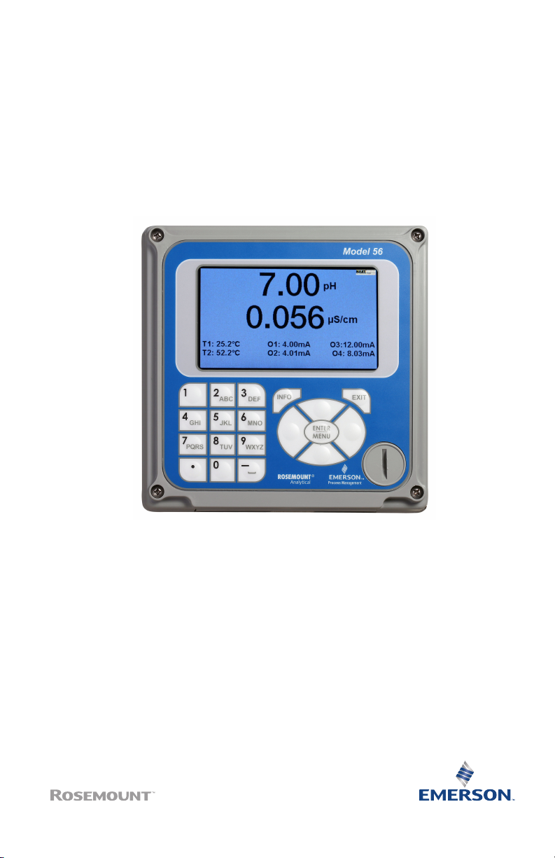
Rosemount™ 56
Dual Channel Transmitter
Quick Start Guide
00825-0100-3056, Rev AB
March 2020
Page 2

Quick Start Guide March 2020
Safety Information
Your instrument purchase from Emerson is one of the finest available for your particular application.
These instruments have been designed and tested to meet many national and international standards.
Experience indicates that its performance is directly related to the quailty of the installation and
knowledge of the user in operating and maintaining the instrument. To ensure its continued operation
to the design specifications, personnel should read this Quick Start Guide thoroughly before
proceeding with installation, commissioning, operation, and maintenance of this instrument. If this
equipment is used in a manner not specified by the manufacturer, the protection provided by it against
hazards may be impaired.
• Failure to follow the proper instructions may cause any one of the following situations to occur:
loss of life, personal injury, property damage, damage to this instrument, and warranty
invalidation.
• Ensure that you have received the correct model and options from your purchase order. Verify
that this Quick Start Guide covers your model and options. If it does not, call 800 854 8257 or 949
757 8500 to request the correct Quick Start Guide.
• For clarification of instructions, contact your Rosemount representative.
• Follow all warnings, cautions, and instructions marked on and supplied with the product.
• Use only qualified personnel to install, operate, program, and maintain the product.
• Install equipment as specified in the Installation section of this Quick Start Guide. Follow
appropriate local and national codes. Only connect the product to electrical and pressure sources
specified in this Quick Start Guide.
• Use only factory documented components for repair. Tampering or unauthorized substitution of
parts can affect product performance and cause unsafe operation of your process.
• All equipment doors must be closed, and protective covers must be in place unless qualified
personnel are performing maintenance.
WARNING
Risk of electrical shock
Installation and servicing of this product may expose personnel to dangerous voltages.
Equipment protected throughout by double insulation.
Disconnect main power wired to separate power source before servicing.
Do not operate or energize instrument with case open.
Signal wiring within this box must be rated at least 240 V for European mains operation.
Non-metallic cable strain reliefs do not provide grounding between conduit connections. Use
grounding type bushings and jumper wires.
Unused cable conduit entries must be securely sealed by non-flammable closures to provide
exposure integrity in compliance with personal safety and environmental protection
requirements. Unused conduit openings must be sealed with Type 4X or IP66 conduit plugs to
maintain the ingress protection rating (Type 4X).
Electrical installation must be in accordance with the National Electrical Code (ANSI/NFPA-70)
and/or any other national or local codes.
Operate only with front panel fastened and in place.
Safety and performance require that this instrument be connected and properly grounded
through a three-wire power source.
Proper use and configuration is the operator's responsibility.
2 Emerson.com/Rosemount
Page 3

March 2020 Quick Start Guide
CAUTION
Radio interference
This product generates, uses, and can radiate radio frequency energy and thus can cause radio
communication interference. Improper installation or operation may increase such interference. As
temporarily permitted by regulation, this unit has not been tested for compliance within the limits of
Class A computing devices, pursuant to Subpart J of Part 15 of FCC rules, which are designed to provide
reasonable protection against such interference.
Operation of this equipment in a residential area may cause interference, in which case the
operator, at his own expense, will be required to take whatever measures may be required to
correct the interference.
CAUTION
This product is not intended for use in the light industrial, residential, or commercial environments per
the instrument's certification in ENG1226-1: 2006.
WARNING
Physical access
Unauthorized personnel may potentially cause significant damage to and/or misconfiguration of end
users’ equipment. This could be intentional or unintentional and needs to be protected against.
Physical security is an important part of any security program and fundamental to protecting your
system. Restrict physical access by unauthorized personnel to protect end users’ assets. This is true for
all systems used within the facility.
Contents
First steps.....................................................................................................................................5
Install......................................................................................................................................... 13
Wire........................................................................................................................................... 16
Navigating the display................................................................................................................22
Start up transmitter....................................................................................................................26
Product certifications................................................................................................................. 28
Declaration of Conformity..........................................................................................................30
China RoHS table........................................................................................................................32
Quick Start Guide 3
Page 4

Quick Start Guide March 2020
4 Emerson.com/Rosemount
Page 5
March 2020 Quick Start Guide
1 First steps
1.1 Unpack and inspect
Procedure
1. Inspect the shipping container. If it is damaged, contact the shipper
immediately for instructions.
2. If there is no apparent damage, unpack the container. Be sure all
items shown on the packing list are present. If items are missing,
notify Emerson immediately.
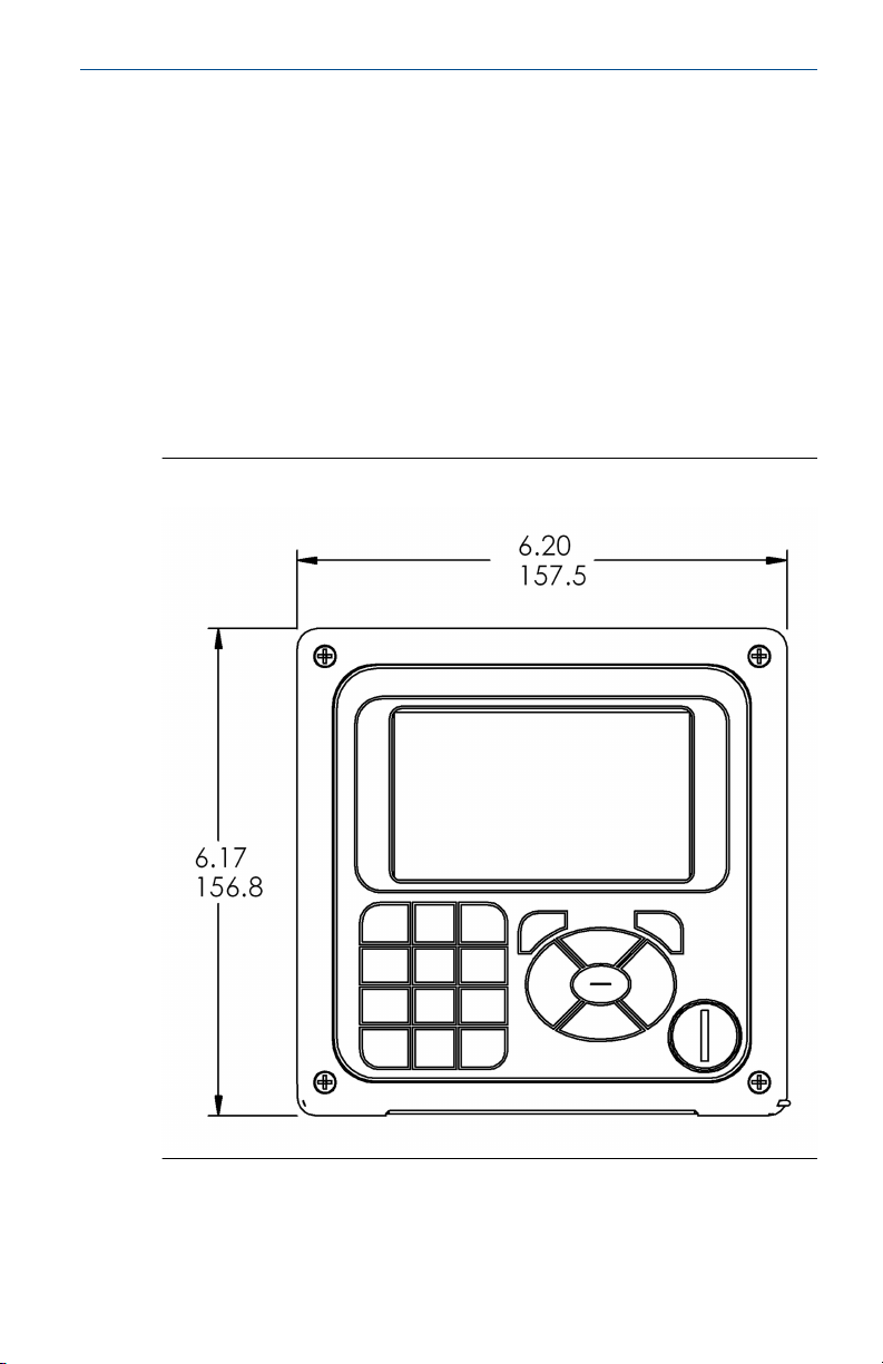
1.2 Mount
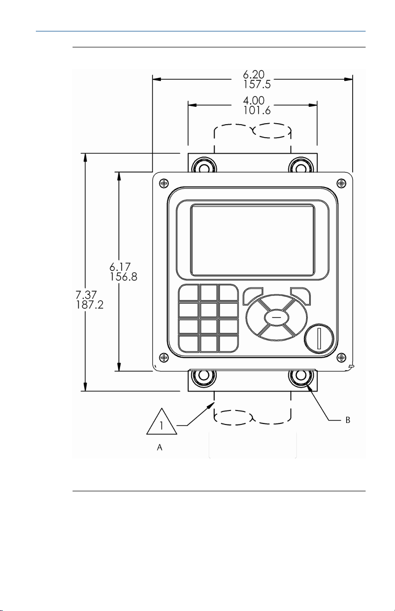
Figure 1-1: Panel Mount Front View
Quick Start Guide 5
Page 6
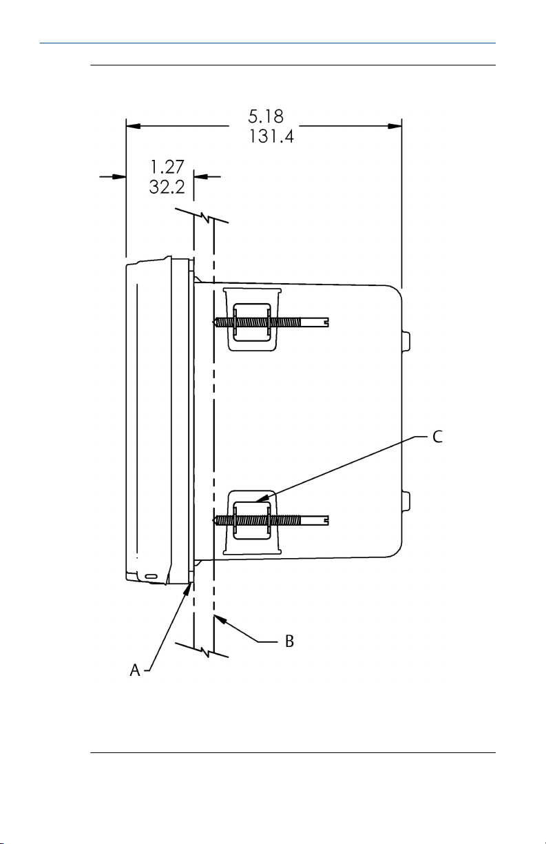
Quick Start Guide March 2020
Figure 1-2: Panel Mount Side View
A. Panel mount gasket
B. Panel supplied by others. Maximum thickness: .375 in. (9.52 mm)
C. 4X mounting bracket and screws provided with instrument
6 Emerson.com/Rosemount
Page 7
March 2020 Quick Start Guide
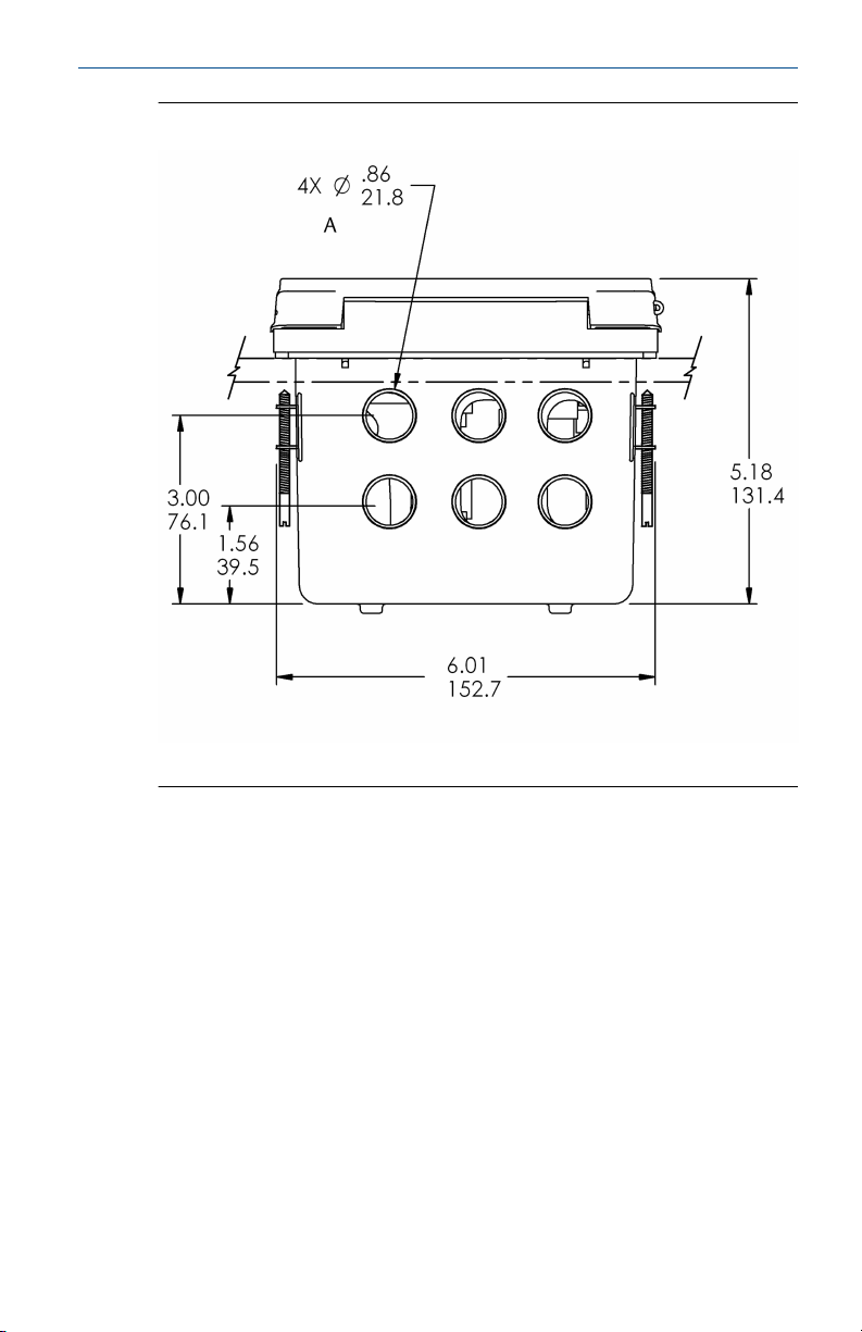
Figure 1-3: Panel Mount Bottom View
A. Conduit openings
Quick Start Guide 7
Page 8
Quick Start Guide March 2020
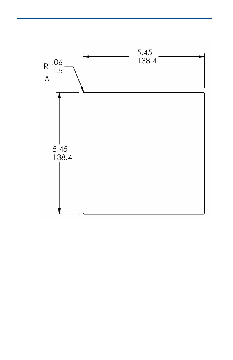
Figure 1-4: Panel Mount Panel Cut-Out
A. Maximum
8 Emerson.com/Rosemount
Page 9
March 2020 Quick Start Guide
Figure 1-5: Wall Mount Front View
A. 2-in. (50.8 mm) pipe supplied by customer
B. Four cover screws
Quick Start Guide 9
Page 10
Quick Start Guide March 2020
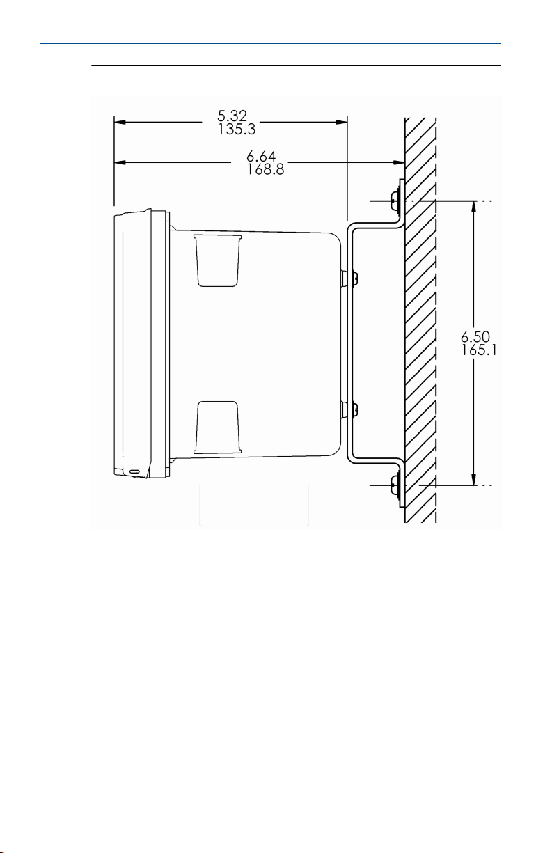
Figure 1-6: Wall Mount Side View
10 Emerson.com/Rosemount
Page 11
March 2020 Quick Start Guide
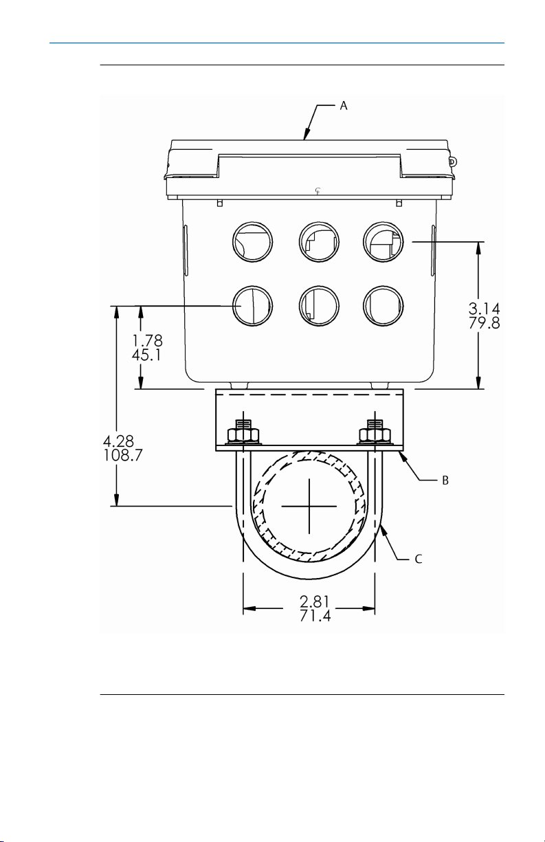
Figure 1-7: Pipe Mount Bottom View
A. Front panel
B. 2-in. (50.8 mm) pipe mount bracket
C. Two sets U-bolts for 2-in. (50.8 mm) pipe in kit PN 23820-00
Quick Start Guide 11
Page 12

Quick Start Guide March 2020
Figure 1-8: Pipe Mount Side View
12 Emerson.com/Rosemount
Page 13

March 2020 Quick Start Guide
2 Install
2.1 General installation information
1. Install the transmitter with a sunshield or out of direct sunlight and
areas with extreme temperatures. The transmitter cannot be
operated in ambient (shaded) conditions greater than 140 °F (60 °C).
2. Install the transmitter in an area where vibration and
electromagnetic and radio frequency interference are minimized or
absent.
3. Keep the transmitter and sensor wiring at least one foot from high
voltage conductors. Be sure there is easy access to the transmitter.
4. The transmitter is suitable for panel, pipe, or surface mounting. Refer
to Mount.
5. Install cable gland fittings and plugs as needed to properly seal the
transmitter on all six enclosure openings. The USB port cover must be
fully installed on the front cover to ensure proper transmitter sealing.
WARNING
Risk or electrical shock
Electrical installation must be in accordance with the National Electric Code
(ANSI/NFPA-70) and/or any other applicable national or local codes.
This symbol identifies a risk of electrical shock.
This symbol identifies a potential hazard. When this symbol
appears, consult the manual for appropriate action.
2.2 Prepare conduit openings
There are six conduit openings in all configurations of the transmitter.
Note
Emerson fits four of the openings with plugs upon shipment.
Quick Start Guide 13
Page 14

Quick Start Guide March 2020
Figure 2-1: Conduit Openings
A. Front panel/keypad
B. Power leads
C. Alarm relay leads
D. Sensor 1 cable
E. 4-20 mA/HART®/Profibus® leads
F. Sensor 2 cable
G. Spare opening
Note
Always use proper cable gland fittings and plugs for wire and cable
installations.
Conduit openings accept ½-in. (12.7 mm) conduit fittings or PG13.5 cable
glands. To keep the case watertight, block unused openings with Type 4X or
IP66 conduit plugs.
To maintain ingress protection for outdoor use, seal unused conduit holes
with suitable conduit plugs.
14 Emerson.com/Rosemount
Page 15

March 2020 Quick Start Guide
Note
Use watertight fittings and hubs that comply with your requirements.
Connect the conduit hub to the conduit before attaching the fitting to the
transmitter.
Quick Start Guide 15
Page 16

Quick Start Guide March 2020
3 Wire
3.1 General wiring information
The transmitter is easy to wire.
The front panel is hinged at the bottom. The panel swings down for easy
access to the wiring locations.
3.1.1 Removable connectors and signal input boards
The transmitter uses removable signal input boards and communication
boards for ease of wiring and installation.
You can remove each of the signal boards either partially or completely from
the enclosure for wiring. The transmitter has three slots for placement of up
to two signal input boards and one communication board.
Slot 1 - left Slot 2 - center Slot 3 - right
Profibus® board Signal board 1 Signal board 2
3.1.2 Signal input boards
Slots 2 and 3 are for signal input measurement boards.
Procedure
1. Wire the sensor leads to the measurement board following the lead
locations marked on the board.
2. Carefully slide the wired board fully into the enclosure slot and take
up the excess sensor cable through the cable gland.
3. Tighten the cable gland nut to secure the cable and ensure a sealed
enclosure.
Note
For the purpose of replacing factory-installed signal input boards,
Rosemount is the sole supplier.
3.1.3 Digital communication boards
HART® digital communication is standard on the transmitter. HART versions
5 and 7 are available on the transmitter and can be switched using the local
keypad. A Profibus® DP communication board is available as an option for
transmitter communication with a host.
HART communications support Bell 202 digital communications over an
analog 4-20 mA current output. Profibus DP is an open communications
protocol which operates over a dedicated digital line to the host.
16 Emerson.com/Rosemount
Page 17

March 2020 Quick Start Guide
3.1.4 Alarm relays
Emerson supplies four alarm relays with the switching power supply (85 to
264 Vac, 03 order code) and the 24 Vdc power supply (20 - 30 Vdc, 02 order
code). You can use all relays for process measurement(s) or temperature.
You can also configure any relay as a fault alarm instead of a process alarm.
In addition, you may configure any relay independently and program it to
activate pumps or control valves.
As process alarms, alarm logic (high or low activation or USP*) and
deadband are user-programmable. Customer-defined failsafe operation is
supported as a programmable menu function to allow all relays to be
energized or not energized as a default condition upon powering the
transmitter. You may program the USP* alarm to activate when the
conductivity is within a user-selectable percentage of the limit. USP*
alarming is available only when a contacting conductivity measurement
board is installed.
3.2 HART® current output wiring
Emerson ships all instruments with four 4-20 mA analog outputs.
Wire the relay leads on each of the independent relays to the correct
position on the main board using the lead markings (+/positive, -/negative)
on the board. Emerson provides male mating connectors with each unit.
3.3 Wire sensor to transmitter
Procedure
1. Wire the correct sensor leads to the main board using the lead
locations marked directly on the board.
2. Carefully slide the wired board fulling into the enclosure slot and take
up the excess sensor cable through the cable gland.
CAUTION
Keep sensor and output signal wiring separate from loop power
wiring. Do not run sensor and power wiring in the same conduit or
close together in a cable tray.
Quick Start Guide 17
Page 18

Quick Start Guide March 2020
Figure 3-1: Power Wiring for 24 Vdc Power Supply (02 Order Code) PN
24365-00
A. To main board (ribbon cable)
B. Rosemount 56 DC power supply board PN 24365-00
18 Emerson.com/Rosemount
Page 19

March 2020 Quick Start Guide
Figure 3-2: Power Wiring for 85-264 Vac Power Supply (03 Order Code)
PN 24538-00
A. Earth ground
B. Neutral
C. Line power
D. To main board (ribbon cable)
E. Rosemount 56 AC power supply board PN 24358-00
Quick Start Guide 19
Page 20

Quick Start Guide March 2020
Figure 3-3: Output Wiring for Main PCB PN 24308-00
A. To power supply PCB (ribbon cable)
B. To digital I/O comm. board
C. To sensor 1 signal board
D. To sensor 2 signal board
E. Hinge pin
F. Transmitter main board, CPU PCB PN 24308-00
G. Hinge pin
20 Emerson.com/Rosemount
Page 21

March 2020 Quick Start Guide
For recommended wire entry points, see Figure 2-1.
Figure 3-4: Contacting Conductivity Signal Board and Sensor Cable Leads
Quick Start Guide 21
Page 22

Quick Start Guide March 2020
4 Navigating the display
4.1 User interface
The transmitter has a large display which shows two live measurement
readouts in large digits and up to six additional process variables or
diagnostic parameters concurrently. The display is back-lit, and you can
customize the format to meet your requirements. You can use an alphanumeric keypad, similar to a cell phone keypad, to enter data during
programming and calibration or lengthy tags to describe process points,
sensors, or instrumentation.
22 Emerson.com/Rosemount
Page 23

March 2020 Quick Start Guide
4.2 Instrument keypad
There are three function keys, four navigation keys, and an alpha-numeric
keypad on the instrument keypad.
Function keys
Use the ENTER/MENU key to access menus for programming and calibrating
the instrument as well as retrieving sorted data. Eight top-level menu items
appear when you press ENTER/MENU.
• Calibrate: Calibrate the attached sensor(s) and analog output(s).
• Program: Program outputs, measurement, temperature, and security
codes.
• Hold: Suspend current outputs.
• Display Setup: Program graphic trend display, brightness, main display
format, tags, language, and warnings.
• Data storage and retrieval: Enable data and event storage, download data,
and view events.
• HART® or Profibus®: Program HART and Profibus communication
parameters.
• Time and Date: Set and view real-time clock settings.
• Reset: Reset all instrument settings, calibration settings, or current
outputs to factory defaults.
You can also use the ENTER/MENU key to enter selections or enable
programming and calibration steps.
Use the EXIT key to return to the previous menu level.
Use the INFO key to display detailed instructions and explanations during
programming and calibration procedures. You can also use it to see
troubleshooting tips for all faults and warnings that may occur during
calibration or continuous operation in process.
Navigation keys
The four navigation keys arranged around the ENTER/MENU key operate in
an intuitive manner similar to the navigation keys on a computer keyboard.
During menu operation, use these keys to move the highlighted screen
selection to another adjacent screen item. During tag entry, use the Left key
is used to delete entries during active alpha-numeric character entry.
Alpha-numeric keypad
The alpha-numeric keypad has 12 keys as outlined below.
• Nine keys are alpha-numeric.
Quick Start Guide 23
Page 24

Quick Start Guide March 2020
• One key is a dedicated 1 key.
• One key is a dedicated 0 key.
• One key is a dedicated "." (decimal point) key.
The alpha-numeric keypad operates the same as entries on a mobile phone.
The nine alpha-numeric keys have multiple characters that you can use for
tag entries or during programming and calibration steps. Make character
selections by pressing the key multiple times to toggle the characters that
are available on each key.
4.3 Main display
The transmitter displays one or two primary measurement values, up to six
secondary measurement values, a Fault and Warning banner, alarm relay
flags, and a digital communications icon.
Process measurements
Two process variables are displayed if two signal boards are installed. One
process variable and process temperature are displayed if one signal board is
installed with one sensor. The upper display area shows the Sensor 1 process
reading. The center display area shows the Sensor 2 process reading. For
dual conductivity, you can assign the upper and center display areas to
different process variables as follows:
Process variables for upper display example
Measure 1 Measure 1
% Reject Measure 2
% Pass % Reject
Ratio % Pass
Process variables for center display example
Ratio
Blank
For single input configurations, the upper display area shows the live process
variable, and you can assign the center display area to Temperature or Blank.
Secondary values
Up to six secondary values are shown in display quadrants at the bottom half
of the screen. You can program all six secondary value positions to any
displayable parameter available.
24 Emerson.com/Rosemount
Page 25

March 2020 Quick Start Guide
4.4 Menu system
The menu system is similar to a computer. Press the ENTER/MENU key at
any time to open the top-level menu including Calibration, Hold,
Programming, Display, Data, and HART® functions. To find a menu item, use
the directional navigation keys to highlight a menu item. Press ENTER/
MENU, direct the cursor to the desired operation, and follow the screen
prompts. Press the BACK screen control available on some menu screens to
revert to the immediate previous menu screen. Press the EXIT key to return
to the previous hierarchical menu level.
Fault and Warning banners
If the transmitter detects a problem with itself or the sensor, the Fault
banner (red) and/or Warning banner (yellow) appears at the bottom of the
main display. A fault requires immediate attention. A warning indicates a
problematic condition or an impending failure. For detailed troubleshooting
assistance, press INFO.
Quick Start Guide 25
Page 26

Quick Start Guide March 2020
5 Start up transmitter
Procedure
1. Wire sensor(s) to the signal boards.
See Wire for wiring instructions. Refer to the sensor Quick Start
Guide for additional details. Make current output, alarm relay, and
power connections.
2. Once connections are secured and verified, apply power to the
transmitter.
WARNING
Electrical shock
Electrical installation must be in accordance with the National
Electrical Code (ANSI/NFPA-70) and/or any other applicable national
or local codes.
This symbol identifies a risk of electical shock.
This symbol identifies a potential hazard. When this symbol
appears, consult the manual for appropriate action.
When the transmitter is powered up for the first time, Quick Start
screens appear. Quick Start operating tips are as follows:
a. Window screens appear. The field with the focus appears with
dark blue back-lighting. To edit the field with focus, press
ENTER/MENU.
b. The Time and Date screen to set the real-time clock appears.
To accept the displayed time, press ENTER on Time and date
OK. To change the date and time, press Down to navigate to
Change the time and date.
3. To choose the language, press ENTER/MENU to edit the active field
and scroll to the language of choice. Press ENTER/MENU and then
press Down to highlight NEXT.
The navigation rules for operating the keypad are displayed.
4. Choose the measurement for Sensor 1 and Sensor 2.
Keypad operation guidlines appear to guide you on how to operate
the user interface.
26 Emerson.com/Rosemount
Page 27

March 2020 Quick Start Guide
Note
To edit a field with backlit focus, press ENTER/MENU. To scroll up or
down, use the keys above or below the ENTER key. To move the
cursor left or right, use the keys to the left or right of the ENTER key.
To edit a numeric value including decimal points, use the
alphanumeric keypad and then press ENTER.
Note
Press ENTER to store a setting or value. Press EXIT to leave without
storing changes. Press EXIT during Quick Start to return the display
to the initial startup screen (Select language). To proceed to the next
Quick Start step, use the Right or Down key to hightlight NEXT. Press
ENTER.
After the last step, the main display appears. The current outputs are
assigned to default values before probes are wired to the transmitter.
5. To change output and all settings, press ENTER/MENU from the live
screen. Using the Down and Right keys, select a menu and navigate
to the screen of choice.
6. To return the transmitter to the factory default settings, choose
Reset under the Menu selection screen.
Please call Rosemount Customer Support Center at 1-800-854-8527
if you need further support.
Quick Start Guide 27
Page 28

Quick Start Guide March 2020
6 Product certifications
Rev 1.0
6.1 European Directive information
A copy of the EU Declaration of Conformity can be found at the end of the
Quick Start Guide. The most recent revision of the EU Declaration of
Conformity can be found at Emerson.com/Rosemount.
6.2 Ordinary location certification
As standard, the transmitter has been examined and tested to determine
that the design meets the basic electrical, mechanical, and fire protection
requirements by a nationally recognized test laboratory (NRTL) as accredited
by the Federal Occupational Safety and Health Administration (OSHA).
6.3 Installing equipment in North America
The US National Electrical Code® (NEC) and the Canadian Electrical Code
(CEC) permit the use of Division marked equipment in Zones and Zone
marked equipment in Divisions. The markings must be suitable for the area
classification, gas, and temperature class. This information is clearly defined
in the respective codes.
6.4 USA
6.4.1 FM hazardous locations
Certificate
Standards
Markings
Special Conditions for Safe Use (X):
1. Sensors having exposed electrodes in the process will be used in a
non-flammable liquid only.
28 Emerson.com/Rosemount
FM17US0028X
FM Class 3600:2011
FM Class 3611:2004
FM Class 3810:2005
ANSI/IEC 60529:2004
Non-incendive Class I, Division 2, Groups ABCD
T4 Tamb -10 °C to +60 °C; dust tight
Class II, Division 2, Groups EFG; Class III
Per Drawing 1400667
IP66 enclosure
Page 29

March 2020 Quick Start Guide
6.4.2 CSA hazardous locations
Certificate
Standards
Markings
70173522
CSA Standard C22.2 No. 010, CSA Standard C22.2 No.
0.4-04, CSA Standard C22.2 No. 25-1966, CSA Standard
C22.2 No. 94-M1991, CSA Standard C22.2 No. 142M1987, CSA Standard C22.2 No. 213-M1987, CSA
Standard C22.2 No. 60529:05 (reaffirmed 2015),
ANSI/IEC 60529-2004 (reaffirmed 2011), ANSI/ISA
12.12.01: 2007, UL Standard No. 50, 11th edition, UL
Standard No. 508, 17th edition
Class I, Division 2, Groups A,B, C, and D;
Class II, Division 2, Groups E, F, and G; Class III
Maximum ambient 60 °C T4 Type 4X enclosure, IP66
6.4.3 UL ordinary locations
Certificate
Standards
Markings
20160921-E207618
UL 61010-1, CAN/CSA C22.2 No. 61010-1
6.5 Canada
6.5.1 CSA hazardous locations
Certificate
Standards
Markings
Quick Start Guide 29
70173522
CSA Standard C22.2 No. 010, CSA Standard C22.2 No.
0.4-04, CSA Standard C22.2 No. 25-1966, CSA Standard
C22.2 No. 94-M1991, CSA Standard C22.2 No. 142M1987, CSA Standard C22.2 No. 213-M1987, CSA
Standard C22.2 No. 60529:05 (reaffirmed 2015),
ANSI/IEC 60529-2004 (reaffirmed 2011), ANSI/ISA
12.12.01: 2007, UL Standard No. 50, 11th edition, UL
Standard No. 508, 17th edition
Class I, Division 2, Groups A,B, C, and D;
Class II, Division 2, Groups E, F, and G; Class III
Maximum ambient 60 °C T4 Type 4X enclosure, IP66
Page 30

Quick Start Guide March 2020
A Declaration of Conformity
Note
Please see website for most recent Declaration.
30 Emerson.com/Rosemount
Page 31

March 2020 Quick Start Guide
Quick Start Guide 31
Page 32

Quick Start Guide March 2020
B China RoHS table
32 Emerson.com/Rosemount
Page 33

March 2020 Quick Start Guide
Quick Start Guide 33
Page 34

Quick Start Guide March 2020
34 Emerson.com/Rosemount
Page 35

March 2020 Quick Start Guide
Quick Start Guide 35
Page 36

GLOBAL HEADQUARTERS
6021 Innovation Blvd.
Shakopee, MN 55379
+1 866 347 3427
+1 952 949 7001
RMTNA.RCCPO@Emerson.com
*00825-0100-3056*
Quick Start Guide
00825-0100-3056, Rev. AB
March 2020
NORTH AMERICA
Emerson Automation Solutions
8200 Market Blvd
Chanhassen, MN 55317
Toll Free +1 800 999 9307
F +1 952 949 7001
RMTNA.RCCPO@Emerson.com
MIDDLE EAST AND AFRICA
Emerson Automation Solutions
Emerson FZE
Jebel Ali Free Zone
Dubai, United Arab Emirates, P.O. Box
17033
+971 4 811 8100
+971 4 886 5465
RMTNA.RCCPO@Emerson.com
Linkedin.com/company/Emerson-
Automation-Solutions
twitter.com/rosemount_news
Facebook.com/Rosemount
youtube.com/RosemountMeasurement
EUROPE
Emerson Automation Solutions
Neuhofstrasse 19a PO Box 1046
CH-6340 Baar
Switzerland
+41 (0) 41 768 6111
+41 (0) 41 768 6300
RMTNA.RCCPO@Emerson.com
ASIA-PACIFIC
Emerson Automation Solutions
1 Pandan Crescent
Singapore 128461
Republic of Singapore
+65 6 777 8211
+65 6 777 0947
RMTNA.RCCPO@Emerson.com
©
2020 Emerson. All rights reserved.
The Emerson logo is a trademark and service
mark of Emerson Electric Co. Rosemount is a
mark of one of the Emerson family of companies.
All other marks are the property of their
respective owners.
 Loading...