


Quick Start Guide
00825-0500-4408, Rev AA
October 2017
Rosemount™ 5408 and 5408:SIS Level
Transmitters
Process Seal Antenna

October 2017
2
Quick Start Guide
1.0 About this guide
This Quick Start Guide provides basic guidelines for the Rosemount 5408 and
5408:SIS Level Transmitters.
Refer to the Rosemount 5408 and 5408:SIS Reference Manual
for more
instructions. The manual and this guide are also available electronically on
Emerson.com/Rosemount
.
Failure to follow safe installation and service guidelines could result in death or serious injury.
Make sure the transmitter is installed by qualified personnel and in accordance with applicable code of
practice.
Use the equipment only as specified in this guide and the Rosemount 5408 and 5408:SIS Reference Manual
.
For installations in hazardous locations, the transmitter must be installed according to the Rosemount 5408
and 5408:SIS Product Certifications
document and System Control Drawing (D7000002-885).
Repair, e.g. substitution of components etc. may jeopardize safety and is under no circumstances allowed.
Explosions could result in death or serious injury.
Verify that the operating environment of the transmitter is consistent with the appropriate hazardous
locations certifications.
Before connecting a Field Communicator in an explosive atmosphere, make sure the instruments in the
loop are installed in accordance with intrinsically safe or non-incendive field wiring practices.
Do not remove the transmitter covers in explosive atmospheres when the circuit is alive.
Both transmitter covers must be fully engaged to meet explosion-proof requirements.
Electrical shock can result in death or serious injury.
Avoid contact with the leads and the terminals. High voltage that may be present on leads can cause
electrical shock.
Make sure the main power to the transmitter is off and the lines to any other external power source are
disconnected or not powered while wiring the transmitter.
Process leaks could result in death or serious injury.
Make sure that the transmitter is handled carefully. If the process seal is damaged, gas might escape from
the tank.
Hot surfaces
The flange and process seal may be hot at high process temperatures.
Allow to cool before servicing.

Quick Start Guide
3
October 2017
2.0 Confirm approval type
For hazardous locations transmitters labeled with multiple approval types:
Permanently mark the checkbox of the selected approval type(s).
Contents
Confirm approval type . . . . . . . . . . . . . . . . . . . . . . . . . . . . . . . . . . . . . . . . . . . . . . . . . . . . . . . . . . . page 3
Mount the transmitter . . . . . . . . . . . . . . . . . . . . . . . . . . . . . . . . . . . . . . . . . . . . . . . . . . . . . . . . . . . page 4
Align transmitter head . . . . . . . . . . . . . . . . . . . . . . . . . . . . . . . . . . . . . . . . . . . . . . . . . . . . . . . . . . . page 8
Adjust display orientation (optional) . . . . . . . . . . . . . . . . . . . . . . . . . . . . . . . . . . . . . . . . . . . . . . page 10
Prepare the electrical connections . . . . . . . . . . . . . . . . . . . . . . . . . . . . . . . . . . . . . . . . . . . . . . . . page 11
Connect wiring and power up . . . . . . . . . . . . . . . . . . . . . . . . . . . . . . . . . . . . . . . . . . . . . . . . . . . . page 12
Configure transmitter using Guided Setup . . . . . . . . . . . . . . . . . . . . . . . . . . . . . . . . . . . . . . . . . page 17

October 2017
4
Quick Start Guide
3.0 Mount the transmitter
3.1 Installation procedure
Flanged version
Tri Clamp version
page 5
page 7

Quick Start Guide
5
October 2017
3.2 Flanged version
Step 1: Lower the transmitter into the nozzle
Note
Be careful not to scratch or otherwise damage the PTFE sealing.
PTFE sealing

October 2017
6
Quick Start Guide
Step 2: Tighten the bolts and nuts
Note
Re-tighten after 24 hours and again after the first temperature cycle.
Check at regular intervals and re-tighten if necessary.
Step 3: Align the transmitter head (see page 8)
Table 1. Torque Value, lb-ft (N-m)
(1)(2)
1. The conditions used for the calculation are: Standard mating metal flange, A193 B8M Cl.2 / A4-70
bolt material, and a friction coefficient of μ=0.16.
2. Low strength bolt and non-metallic mating flange may require lower tightening torque.
Process
connection size
Process connection rating
ASME B16.5 EN1092-1 JIS B2220
Class 150 Class 300 PN6 PN10/PN16 PN25/PN40 10K
2-in./DN50/50A 29 (40) 52 (70) 15 (20) 26 (35) 29 (40) 18 (25)
3-in./DN80/80A 33 (45) 48 (65) 37 (50) 37 (50) 41 (55) 22 (30)
4-in./DN100/100A 59 (80) 52 (70) 37 (50) 37 (50) 74 (100) 26 (35)

Quick Start Guide
7
October 2017
3.3 Tri Clamp version
Step 1: Lower the transmitter into the nozzle
Note
Be careful not to scratch or otherwise damage the PTFE sealing.
Step 2: Tighten the clamp
Tighten the clamp to the recommended torque (see the manufacturer’s
instruction manual).
Step 3: Align the transmitter head (see page 8)
PTFE sealing

October 2017
8
Quick Start Guide
4.0 Align transmitter head
Open tank
Align the marking on sensor module toward the tank wall.
Still pipe
Align the external ground screw toward the holes of the still pipe.
Chamber
Align the external ground screw toward the process connections.

Quick Start Guide
9
October 2017
Step 1: Loosen the nut slightly and turn the transmitter
Step 2: Verify transmitter is properly aligned
See page 8 for direction.
Step 3: Tighten the nut
Torque 355 in-lb (40 N-m)
60 mm

October 2017
10
Quick Start Guide
5.0 Adjust display orientation (optional)
To improve field access to wiring or to better view the optional LCD display:
1. Loosen the set screw until the transmitter housing can rotate smoothly.
2. First, rotate the housing clockwise to the desired location. If the desired
location cannot be achieved due to thread limit, rotate the housing
counterclockwise to the desired location (up to 360° from thread limit).
3. Re-tighten the set screw.
Figure 1. Rotate the Transmitter Housing
H3/32 in.
Torque 30 in-lb (3 N-m)

Quick Start Guide
11
October 2017
6.0 Prepare the electrical connections
Cable selection
Use 24-14 AWG wire. Twisted pairs and shielded wiring are recommended for
environments with high EMI (electromagnetic interference).
Two wires can be safely connected to each terminal screw.
Cable gland/conduit
For explosion-proof/flameproof installations, only use cable glands or conduit
entry devices certified explosion-proof or flameproof.
Power supply
The transmitter operates on 12-42.4 Vdc (12-30 Vdc in Intrinsically Safe
installations) at the transmitter terminals.
Power consumption
Max. 1 W, current max. 23 mA
Load limitations
For HART® communication, a minimum loop resistance of 250 is required.
Maximum loop resistance is determined by the voltage level of the external
power supply, as described by Figure 2.
Figure 2. Load Limitations
42.4
2417.8
12
0
400
200
1000
800
600
1200
1400
20 30 40 50
521
250
782
1322
External Power Supply Voltage (Vdc)
Loop Resistance (Ohms)
Maximum Loop Resistance = 43.5 * (External Power Supply Voltage - 12)

October 2017
12
Quick Start Guide
7.0 Connect wiring and power up
Step 1: Verify that the power supply is disconnected
Step 2: Remove the cover
Step 3: Remove the plastic plugs
Step 4: Pull the cable through the cable gland/conduit
½-14 NPT M20 x 1.5
Identification of thread size and type
(No marking =½-14 NPT)

Quick Start Guide
13
October 2017
Step 5: Connect the cable wires
Figure 3. Transmitter Wiring
A. Field Communicator
B. Approved IS barrier (for Intrinsically Safe installations only)
C. HART modem
D. Load resistance (≥250
E. Current meter
F. Power supply
Torq ue 7 in-lb (0.8 N - m )
A
C
B
E
F
-
+
-
+
D
123
456
7809

October 2017
14
Quick Start Guide
Step 6: Ensure proper grounding
Make sure grounding is done according to national and local electrical codes.
Failure to do so may impair the protection provided by the equipment.
Transmitter case grounding
The most effective grounding method is direct connection to earth ground with
minimal impedance. There are two grounding screw connections provided.
Figure 4. Ground Screws
A. Internal ground screw
B. External ground screw
Signal cable shield grounding
Make sure the instrument cable shield is:
Trimmed close and insulated from touching the transmitter housing.
Connected to the next shield if cable is routed through a junction box.
Connected to a good earth ground at the power supply end.
Figure 5. Cable Shield
A.B.Insulate shield
Minimize distance
C.D.Trim shield and insulate
Connect shield back to the power supply ground
A
B
B
BA
CC
C
D
Quick Start Guide
15
October 2017
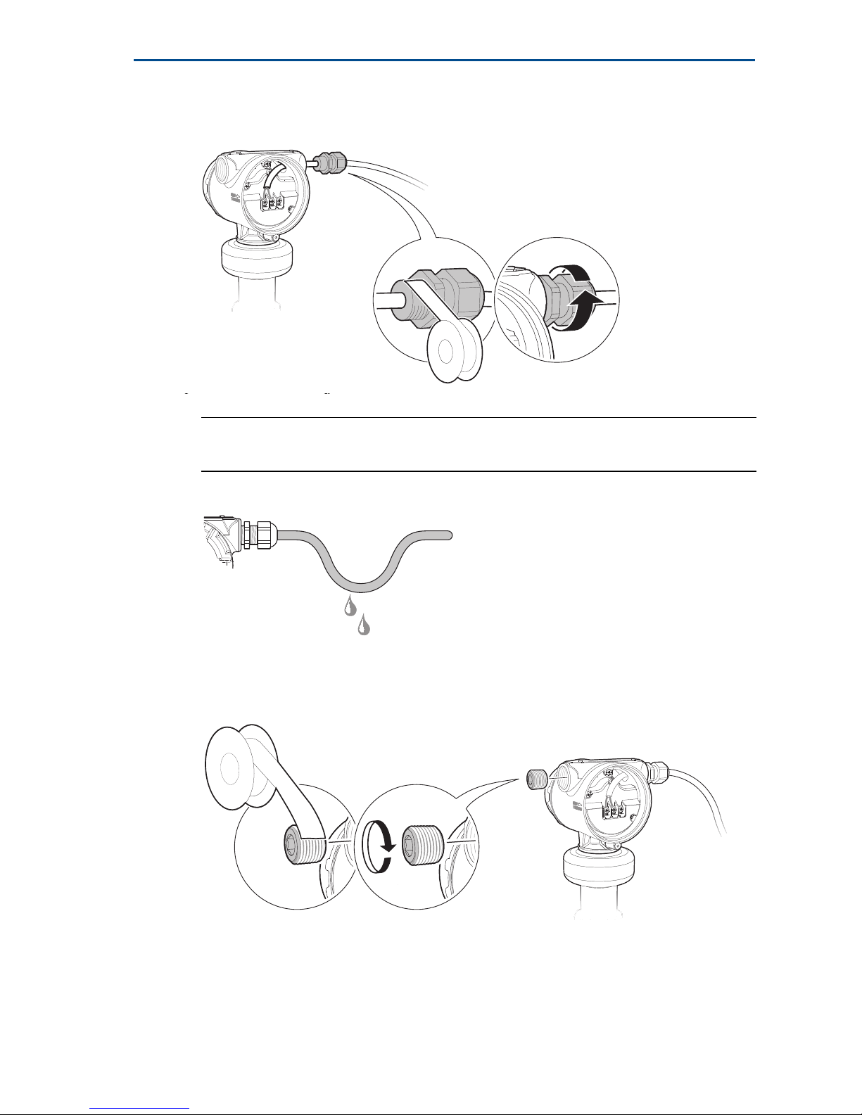
Step 7: Tighten the cable gland
Apply PTFE tape or other sealant to the threads.
Note
Arrange the wiring with a drip loop.
Step 8: Seal any unused port with the enclosed metal plug
Apply PTFE tape or other sealant to the threads.

October 2017
16
Quick Start Guide
Step 9: Attach and tighten the covers
1. Verify the cover jam screws are completely threaded into the housing.
2. Attach and tighten the covers. Make sure the covers are fully engaged.
3. Turn the jam screw counterclockwise until it contacts the cover.
Required for explosion-proof/flameproof installations only.
4. Turn the jam screw an additional ½ turn counterclockwise to secure the
cover.
Step 10: Connect the power supply
It may take up to 15 seconds before the LCD display lights up.
H2.5 mm
Cover jam screw
(one per side)

Quick Start Guide
17
October 2017
8.0 Configure transmitter using Guided Setup
The transmitter can easily be configured by using a PC with the Rosemount
Radar Master Plus software (launched through the Instrument Inspector™
Application), a Field Communicator, the AMS Device Manager, or any other
Device Descriptor (DD) or Field Device Integration (FDI) compatible host
system. Rosemount Radar Master is the recommended tool for configuration.
Rosemount Radar Master Plus
1. Start Instrument Inspector Application.
2. Under HART, double-click the device icon.
3. From the Overview screen, select Rosemount Radar Master Plus
4. Under Configure, select Guided Setup and follow the on-screen instructions.
AMS Device Manager
1. Start AMS Device Manager.
2. Select View > Device Connection View.
3. In the Device Connection View, double-click the HART modem icon.
4. Double-click the device icon.
5. From the Home screen, select Configure > Guided Setup.
6. Select Basic Setup and follow the on-screen instructions.
Field Communicator
1. Turn on the Field Communicator.
2. From the Main Menu, tap the HART symbol. The Field Communicator now
connects to the device.
3. From the Home screen, select Configure > Guided Setup.
4. Select Basic Setup and follow the on-screen instructions.
Get the latest FDI Device Package
The FDI Package or DD is typically installed together with the configuration tool.
Download the latest FDI Package at:
Emerson.com/RosemountRadarMasterPlus
Download the latest DD at:
EmersonProcess.com/devicefiles
Learn more
Visit Emerson.com/Rosemount to download the Rosemount 5408 and 5408:SIS
Reference Manual.

October 2017
18
Quick Start Guide

Quick Start Guide
19
October 2017

Manufactured by
Emerson Automation Solutions
Rosemount Tank Radar AB
Layoutvägen 1
S-435 33 Mölnlycke
Sweden
+46 31 337 00 00
+46 31 25 30 22
Global Headquarters
Emerson Automation Solutions
6021 Innovation Blvd.
Shakopee, MN 55379, USA
+1 800 999 9307 or +1 952 906 8888
+1 952 949 7001
RFQ.RMD-RCC@Emerson.com
North America Regional Office
Emerson Automation Solutions
8200 Market Blvd.
Chanhassen, MN 55317, USA
+1 800 999 9307 or +1 952 906 8888
+1 952 949 7001
RMT-NA.RCCRFQ@Emerson.com
Latin America Regional Office
Emerson Automation Solutions
1300 Concord Terrace, Suite 400
Sunrise, FL 33323, USA
+1 954 846 5030
+1 954 846 5121
RFQ.RMD-RCC@Emerson.com
Linkedin.com/company/Emerson-Automation-Solutions
Twitter.com/Rosemount_News
Facebook.com/Rosemount
Youtube.com/ user/RosemountMeasurement
Google.com/+RosemountMeasurement
Standard Terms and Conditions of Sale can be found at
www.Emerson.com/en-us/Terms-of-Use
The Emerson logo is a trademark and service mark of Emerson
Electric Co.
Instrument Inspector, Rosemount, and Rosemount logotype are
trademarks of Emerson.
HART is a registered trademark of the FieldComm Group.
All other marks are the property of their respective owners.
© 2017 Emerson. All rights reserved.
Europe Regional Office
Emerson Automation Solutions
Neuhofstrasse 19a P.O. Box 1046
CH 6340 Baar
Switzerland
+41 (0) 41 768 6111
+41 (0) 41 768 6300
RFQ.RMD-RCC@Emerson.com
Asia Pacific Regional Office
Emerson Automation Solutions
1 Pandan Crescent
Singapore 128461
+65 6777 8211
+65 6777 0947
Enquiries@AP.Emerson.com
Middle East and Africa Regional Office
Emerson Automation Solutions
Emerson FZE P.O. Box 17033,
Jebel Ali Free Zone - South 2
Dubai, United Arab Emirates
+971 4 8118100
+971 4 8865465
RFQ.RMTMEA@Emerson.com
*00825-0500-4408*
Quick Start Guide
00825-0500-4408, Rev AA
October 2017
 Loading...