

Page 1

Reference Manual
00809-0100-4026, Rev HA
November 2014
Rosemount 5400 Series
Superior Performance Two-Wire Non-Contacting
Radar Level Transmitter
Page 2

Page 3
iii
Reference Manual
00809-0100-4026, Rev HA
November 2014
Rosemount 5400 Series
Read this manual before working with the product. For personal and system safety, and for
optimum product performance, make sure you thoroughly understand the contents before
installing, using, or maintaining this product.
Within the United States, Emerson Process Management has two toll-free assistance
numbers.
Customer Central:
Technical support, quoting, and order-related questions.
United States - 1-800-999-9307 (7:00 am to 7:00 pm CST)
Asia Pacific- 65 777 8211
Europe / Middle East / Africa - 49 (8153) 9390
North American Response Center:
Equipment service needs.
1-800-654-7768 (24 hours a day — includes Canada)
For equipment service or support needs outside the United States, contact your local
Emerson Process Management representative.
There are no health hazards from the Rosemount 5400 Series transmitter. The microwave
power density in the tank is only a small fraction of the allowed power density according to
international standards.
The products described in this document are NOT designed for nuclear-qualified
applications.
Using non-nuclear qualified products in applications that require nuclear-qualified
hardware or products may cause inaccurate readings.
For information on Rosemount nuclear-qualified products, contact your local Emerson
Process Management Sales Representative.
This product is designed to meet FCC and R&TTE requirements.
This device complies with part 15 of the FCC rules. Operation is subjec t to the following t wo
conditions: (1) This device may not cause harmful interference, and (2) this device must
accept any interference received, including interference that may cause undesired
operation.
Page 4

iv
Reference Manual
00809-0100-4026, Rev HA
November 2014
Page 5

v
Reference Manual
00809-0100-4026, Rev HA
Contents
November 2014
Contents
1Section 1: Introduction
1.1 Manual overview . . . . . . . . . . . . . . . . . . . . . . . . . . . . . . . . . . . . . . . . . . . . . . . . . . . . . . . 1
1.2 Service support. . . . . . . . . . . . . . . . . . . . . . . . . . . . . . . . . . . . . . . . . . . . . . . . . . . . . . . . .3
1.3 Product recycling/ disposal . . . . . . . . . . . . . . . . . . . . . . . . . . . . . . . . . . . . . . . . . . . . . . 4
1.4 Safety messages. . . . . . . . . . . . . . . . . . . . . . . . . . . . . . . . . . . . . . . . . . . . . . . . . . . . . . . .4
2Section 2: Transmitter Overview
2.1 Theory of operation . . . . . . . . . . . . . . . . . . . . . . . . . . . . . . . . . . . . . . . . . . . . . . . . . . . . .7
2.2 Application examples . . . . . . . . . . . . . . . . . . . . . . . . . . . . . . . . . . . . . . . . . . . . . . . . . . .8
2.3 System architecture. . . . . . . . . . . . . . . . . . . . . . . . . . . . . . . . . . . . . . . . . . . . . . . . . . . .10
2.4 Process characteristics . . . . . . . . . . . . . . . . . . . . . . . . . . . . . . . . . . . . . . . . . . . . . . . . .12
2.5 Components of the transmitter . . . . . . . . . . . . . . . . . . . . . . . . . . . . . . . . . . . . . . . . .14
2.6 Antenna selection guide/measuring range . . . . . . . . . . . . . . . . . . . . . . . . . . . . . . . .15
3Section 3: Mechanical Installation
3.1 Safety messages. . . . . . . . . . . . . . . . . . . . . . . . . . . . . . . . . . . . . . . . . . . . . . . . . . . . . . .19
3.2 Installation procedure . . . . . . . . . . . . . . . . . . . . . . . . . . . . . . . . . . . . . . . . . . . . . . . . . .21
3.3 Mounting considerations . . . . . . . . . . . . . . . . . . . . . . . . . . . . . . . . . . . . . . . . . . . . . . .22
3.3.1 Mounting location . . . . . . . . . . . . . . . . . . . . . . . . . . . . . . . . . . . . . . . . . . . . . . .22
3.3.2 Special considerations in solids applications . . . . . . . . . . . . . . . . . . . . . . . . .24
3.3.3 Mounting in pipes . . . . . . . . . . . . . . . . . . . . . . . . . . . . . . . . . . . . . . . . . . . . . . . .25
3.3.4 Installation considerations . . . . . . . . . . . . . . . . . . . . . . . . . . . . . . . . . . . . . . . .26
3.3.5 Nozzle considerations . . . . . . . . . . . . . . . . . . . . . . . . . . . . . . . . . . . . . . . . . . . .27
3.3.6 Nozzle recommendations and requirements . . . . . . . . . . . . . . . . . . . . . . . .30
3.3.7 Service space . . . . . . . . . . . . . . . . . . . . . . . . . . . . . . . . . . . . . . . . . . . . . . . . . . . .32
3.3.8 Beamwidth . . . . . . . . . . . . . . . . . . . . . . . . . . . . . . . . . . . . . . . . . . . . . . . . . . . . . .33
3.3.9 Vessel characteristics . . . . . . . . . . . . . . . . . . . . . . . . . . . . . . . . . . . . . . . . . . . . .35
3.3.10Disturbing objects . . . . . . . . . . . . . . . . . . . . . . . . . . . . . . . . . . . . . . . . . . . . . . .35
3.3.11Valves . . . . . . . . . . . . . . . . . . . . . . . . . . . . . . . . . . . . . . . . . . . . . . . . . . . . . . . . . .35
3.4 Mounting . . . . . . . . . . . . . . . . . . . . . . . . . . . . . . . . . . . . . . . . . . . . . . . . . . . . . . . . . . . . .36
3.4.1 Cone antenna flange connection . . . . . . . . . . . . . . . . . . . . . . . . . . . . . . . . . . .36
3.4.2 Process seal antenna . . . . . . . . . . . . . . . . . . . . . . . . . . . . . . . . . . . . . . . . . . . . .37
3.4.3 Rod antenna threaded connection . . . . . . . . . . . . . . . . . . . . . . . . . . . . . . . . .38
3.4.4 Rod antenna flanged connection. . . . . . . . . . . . . . . . . . . . . . . . . . . . . . . . . . .39
3.4.5 Tri-Clamp™ tank connection . . . . . . . . . . . . . . . . . . . . . . . . . . . . . . . . . . . . . .40
Contents
Page 6

vi
Reference Manual
00809-0100-4026, Rev HA
Contents
November 2014
Contents
3.4.6 Bracket mounting on wall . . . . . . . . . . . . . . . . . . . . . . . . . . . . . . . . . . . . . . . . .41
3.4.7 Bracket mounting on pipe. . . . . . . . . . . . . . . . . . . . . . . . . . . . . . . . . . . . . . . . .42
4Section 4: Electrical Installation
4.1 Safety messages. . . . . . . . . . . . . . . . . . . . . . . . . . . . . . . . . . . . . . . . . . . . . . . . . . . . . . .43
4.2 Wiring and power supply requirements. . . . . . . . . . . . . . . . . . . . . . . . . . . . . . . . . . .44
4.3 Cable/conduit entries . . . . . . . . . . . . . . . . . . . . . . . . . . . . . . . . . . . . . . . . . . . . . . . . . .45
4.3.1 Conduit electrical connector wiring (using minifast
®
). . . . . . . . . . . . . . . . .45
4.4 Grounding . . . . . . . . . . . . . . . . . . . . . . . . . . . . . . . . . . . . . . . . . . . . . . . . . . . . . . . . . . . .46
4.5 Cable selection . . . . . . . . . . . . . . . . . . . . . . . . . . . . . . . . . . . . . . . . . . . . . . . . . . . . . . . .46
4.6 Hazardous areas . . . . . . . . . . . . . . . . . . . . . . . . . . . . . . . . . . . . . . . . . . . . . . . . . . . . . . .47
4.7 External circuit breaker . . . . . . . . . . . . . . . . . . . . . . . . . . . . . . . . . . . . . . . . . . . . . . . . .47
4.7.1 Connecting the transmitter . . . . . . . . . . . . . . . . . . . . . . . . . . . . . . . . . . . . . . .47
4.8 HART. . . . . . . . . . . . . . . . . . . . . . . . . . . . . . . . . . . . . . . . . . . . . . . . . . . . . . . . . . . . . . . . .49
4.8.1 Power requirements. . . . . . . . . . . . . . . . . . . . . . . . . . . . . . . . . . . . . . . . . . . . . .49
4.8.2 Load limitations. . . . . . . . . . . . . . . . . . . . . . . . . . . . . . . . . . . . . . . . . . . . . . . . . .49
4.8.3 Non-intrinsically safe power supply . . . . . . . . . . . . . . . . . . . . . . . . . . . . . . . . .51
4.8.4 Intrinsically safe power supply . . . . . . . . . . . . . . . . . . . . . . . . . . . . . . . . . . . . .52
4.8.5 Type N approvals: non-sparking / energy-limited power supply . . . . . . . .53
4.8.6 Transient protection terminal block . . . . . . . . . . . . . . . . . . . . . . . . . . . . . . . .54
4.9 F
OUNDATION fieldbus. . . . . . . . . . . . . . . . . . . . . . . . . . . . . . . . . . . . . . . . . . . . . . . . . . . .55
4.9.1 Power requirements. . . . . . . . . . . . . . . . . . . . . . . . . . . . . . . . . . . . . . . . . . . . . .55
4.9.2 Non-intrinsically safe power supply . . . . . . . . . . . . . . . . . . . . . . . . . . . . . . . . .57
4.9.3 Intrinsically safe power supply . . . . . . . . . . . . . . . . . . . . . . . . . . . . . . . . . . . . .58
4.9.4 Type N approvals: non-sparking / energy-limited power supply . . . . . . . .59
4.10HART to Modbus Converter (HMC) . . . . . . . . . . . . . . . . . . . . . . . . . . . . . . . . . . . . . .60
4.10.1Connecting the transmitter . . . . . . . . . . . . . . . . . . . . . . . . . . . . . . . . . . . . . . .60
4.10.2Connection terminals . . . . . . . . . . . . . . . . . . . . . . . . . . . . . . . . . . . . . . . . . . . .62
4.10.3RS-485 bus. . . . . . . . . . . . . . . . . . . . . . . . . . . . . . . . . . . . . . . . . . . . . . . . . . . . . .63
4.10.4Installation cases . . . . . . . . . . . . . . . . . . . . . . . . . . . . . . . . . . . . . . . . . . . . . . . .63
4.10.5External HART devices (slaves). . . . . . . . . . . . . . . . . . . . . . . . . . . . . . . . . . . . .65
4.11Establish HART communication . . . . . . . . . . . . . . . . . . . . . . . . . . . . . . . . . . . . . . . . .66
4.11.1Connect to the MA/MB terminals . . . . . . . . . . . . . . . . . . . . . . . . . . . . . . . . . .66
4.11.2Connect to the HART terminals . . . . . . . . . . . . . . . . . . . . . . . . . . . . . . . . . . . .68
4.12Optional devices . . . . . . . . . . . . . . . . . . . . . . . . . . . . . . . . . . . . . . . . . . . . . . . . . . . . . .69
4.12.1Tri-Loop™ HART to analog converter . . . . . . . . . . . . . . . . . . . . . . . . . . . . . . .69
4.12.2751 Field Signal Indicator . . . . . . . . . . . . . . . . . . . . . . . . . . . . . . . . . . . . . . . . .70
4.12.3Smart Wireless THUM
™
Adapter . . . . . . . . . . . . . . . . . . . . . . . . . . . . . . . . . . .71
Page 7

vii
Reference Manual
00809-0100-4026, Rev HA
Contents
November 2014
Contents
5Section 5: Basic Configuration/Start-up
5.1 Safety messages. . . . . . . . . . . . . . . . . . . . . . . . . . . . . . . . . . . . . . . . . . . . . . . . . . . . . . .73
5.2 Overview . . . . . . . . . . . . . . . . . . . . . . . . . . . . . . . . . . . . . . . . . . . . . . . . . . . . . . . . . . . . .74
5.2.1 Basic configuration parameters . . . . . . . . . . . . . . . . . . . . . . . . . . . . . . . . . . . .74
5.2.2 Configuration tools . . . . . . . . . . . . . . . . . . . . . . . . . . . . . . . . . . . . . . . . . . . . . .74
5.3 Basic configuration parameters. . . . . . . . . . . . . . . . . . . . . . . . . . . . . . . . . . . . . . . . . .75
5.3.1 Measurement units . . . . . . . . . . . . . . . . . . . . . . . . . . . . . . . . . . . . . . . . . . . . . .75
5.3.2 Tank geometry . . . . . . . . . . . . . . . . . . . . . . . . . . . . . . . . . . . . . . . . . . . . . . . . . .75
5.3.3 Process conditions . . . . . . . . . . . . . . . . . . . . . . . . . . . . . . . . . . . . . . . . . . . . . . .77
5.3.4 Volume configuration . . . . . . . . . . . . . . . . . . . . . . . . . . . . . . . . . . . . . . . . . . . .78
5.3.5 Analog output (HART) . . . . . . . . . . . . . . . . . . . . . . . . . . . . . . . . . . . . . . . . . . . .81
5.3.6 Level and distance calibration . . . . . . . . . . . . . . . . . . . . . . . . . . . . . . . . . . . . .82
5.3.7 Echo tuning . . . . . . . . . . . . . . . . . . . . . . . . . . . . . . . . . . . . . . . . . . . . . . . . . . . . .83
5.3.8 ATC . . . . . . . . . . . . . . . . . . . . . . . . . . . . . . . . . . . . . . . . . . . . . . . . . . . . . . . . . . . .84
5.4 Basic configuration using RRM . . . . . . . . . . . . . . . . . . . . . . . . . . . . . . . . . . . . . . . . . .84
5.4.1 System requirements . . . . . . . . . . . . . . . . . . . . . . . . . . . . . . . . . . . . . . . . . . . . .84
5.4.2 Help in RRM . . . . . . . . . . . . . . . . . . . . . . . . . . . . . . . . . . . . . . . . . . . . . . . . . . . . .85
5.4.3 Installing the RRM software for HART communication . . . . . . . . . . . . . . . .85
5.4.4 Specifying the COM port . . . . . . . . . . . . . . . . . . . . . . . . . . . . . . . . . . . . . . . . . .87
5.4.5 To set the COM port buffers . . . . . . . . . . . . . . . . . . . . . . . . . . . . . . . . . . . . . . .88
5.4.6 Specifying measurement units. . . . . . . . . . . . . . . . . . . . . . . . . . . . . . . . . . . . .88
5.4.7 Installing the RRM software for F
OUNDATION fieldbus . . . . . . . . . . . . . . . . . .88
5.4.8 Specifying measurement units. . . . . . . . . . . . . . . . . . . . . . . . . . . . . . . . . . . . .90
5.4.9 Using the Setup functions . . . . . . . . . . . . . . . . . . . . . . . . . . . . . . . . . . . . . . . . .91
5.4.10Guided setup. . . . . . . . . . . . . . . . . . . . . . . . . . . . . . . . . . . . . . . . . . . . . . . . . . . .92
5.4.11Using the Setup functions. . . . . . . . . . . . . . . . . . . . . . . . . . . . . . . . . . . . . . . 100
5.5 Configuration using a Field Communicator . . . . . . . . . . . . . . . . . . . . . . . . . . . . . 101
5.7 Basic configuration using AMS Suite. . . . . . . . . . . . . . . . . . . . . . . . . . . . . . . . . . . . 105
5.8 Configuration using DeltaV . . . . . . . . . . . . . . . . . . . . . . . . . . . . . . . . . . . . . . . . . . . 106
5.8.1 Advanced configuration . . . . . . . . . . . . . . . . . . . . . . . . . . . . . . . . . . . . . . . . 111
5.9 F
OUNDATION fieldbus overview . . . . . . . . . . . . . . . . . . . . . . . . . . . . . . . . . . . . . . . . . 112
5.9.1 Assigning device tag and node address . . . . . . . . . . . . . . . . . . . . . . . . . . . 113
5.9.2 Foundation fieldbus block operation . . . . . . . . . . . . . . . . . . . . . . . . . . . . . 113
5.10Application examples . . . . . . . . . . . . . . . . . . . . . . . . . . . . . . . . . . . . . . . . . . . . . . . . 115
5.10.1Radar level transmitter - level value . . . . . . . . . . . . . . . . . . . . . . . . . . . . . . 115
5.10.2Radar level transmitter - level value in percent (%). . . . . . . . . . . . . . . . . . 116
5.11Tri-Loop™ HART to Analog Converter . . . . . . . . . . . . . . . . . . . . . . . . . . . . . . . . . . 117
5.12HART multidrop configuration . . . . . . . . . . . . . . . . . . . . . . . . . . . . . . . . . . . . . . . . 118
Page 8

viii
Reference Manual
00809-0100-4026, Rev HA
Contents
November 2014
Contents
6Section 6: Operation
6.1 Safety messages. . . . . . . . . . . . . . . . . . . . . . . . . . . . . . . . . . . . . . . . . . . . . . . . . . . . . 119
6.2 Viewing measurement data. . . . . . . . . . . . . . . . . . . . . . . . . . . . . . . . . . . . . . . . . . . 120
6.2.1 Using the display panel . . . . . . . . . . . . . . . . . . . . . . . . . . . . . . . . . . . . . . . . . 120
6.2.2 Specifying display panel variables . . . . . . . . . . . . . . . . . . . . . . . . . . . . . . . . 120
6.2.3 Viewing measurement data in RRM . . . . . . . . . . . . . . . . . . . . . . . . . . . . . . 124
6.2.4 Viewing measurement data in AMS Suite and DeltaV . . . . . . . . . . . . . . . 125
6.3 LCD display error messages . . . . . . . . . . . . . . . . . . . . . . . . . . . . . . . . . . . . . . . . . . . 126
6.4 LED error messages . . . . . . . . . . . . . . . . . . . . . . . . . . . . . . . . . . . . . . . . . . . . . . . . . . 127
7Section 7: Service and Troubleshooting
7.1 Safety messages. . . . . . . . . . . . . . . . . . . . . . . . . . . . . . . . . . . . . . . . . . . . . . . . . . . . . 129
7.2 Troubleshooting overview . . . . . . . . . . . . . . . . . . . . . . . . . . . . . . . . . . . . . . . . . . . . 131
7.3 Service overview. . . . . . . . . . . . . . . . . . . . . . . . . . . . . . . . . . . . . . . . . . . . . . . . . . . . . 132
7.3.1 Analyzing the measurement signal . . . . . . . . . . . . . . . . . . . . . . . . . . . . . . . 132
7.3.2 Surface pulse not found. . . . . . . . . . . . . . . . . . . . . . . . . . . . . . . . . . . . . . . . . 133
7.3.3 Registration of false echoes . . . . . . . . . . . . . . . . . . . . . . . . . . . . . . . . . . . . . 135
7.3.4 Using the Echo Curve Analyzer. . . . . . . . . . . . . . . . . . . . . . . . . . . . . . . . . . . 137
7.3.5 Using the Echo Curve Analyzer with a Field Communicator . . . . . . . . . . 140
7.4 Analog Output calibration . . . . . . . . . . . . . . . . . . . . . . . . . . . . . . . . . . . . . . . . . . . . 142
7.5 Logging measurement data. . . . . . . . . . . . . . . . . . . . . . . . . . . . . . . . . . . . . . . . . . . 143
7.6 Backing up the transmitter configuration . . . . . . . . . . . . . . . . . . . . . . . . . . . . . . . 144
7.7 Diagnostics . . . . . . . . . . . . . . . . . . . . . . . . . . . . . . . . . . . . . . . . . . . . . . . . . . . . . . . . . 145
7.8 Configuration report . . . . . . . . . . . . . . . . . . . . . . . . . . . . . . . . . . . . . . . . . . . . . . . . . 147
7.9 Viewing input and holding registers. . . . . . . . . . . . . . . . . . . . . . . . . . . . . . . . . . . . 148
7.10Reset to factory settings. . . . . . . . . . . . . . . . . . . . . . . . . . . . . . . . . . . . . . . . . . . . . . 149
7.11Surface search . . . . . . . . . . . . . . . . . . . . . . . . . . . . . . . . . . . . . . . . . . . . . . . . . . . . . . 150
7.12Using the Simulation Mode . . . . . . . . . . . . . . . . . . . . . . . . . . . . . . . . . . . . . . . . . . . 151
7.13Write protecting a transmitter . . . . . . . . . . . . . . . . . . . . . . . . . . . . . . . . . . . . . . . . 152
7.14Diagnostic messages . . . . . . . . . . . . . . . . . . . . . . . . . . . . . . . . . . . . . . . . . . . . . . . . 153
7.14.1Troubleshooting. . . . . . . . . . . . . . . . . . . . . . . . . . . . . . . . . . . . . . . . . . . . . . . 153
7.14.2Device status. . . . . . . . . . . . . . . . . . . . . . . . . . . . . . . . . . . . . . . . . . . . . . . . . . 153
7.14.3Errors. . . . . . . . . . . . . . . . . . . . . . . . . . . . . . . . . . . . . . . . . . . . . . . . . . . . . . . . . 154
7.14.4Warnings . . . . . . . . . . . . . . . . . . . . . . . . . . . . . . . . . . . . . . . . . . . . . . . . . . . . . 155
7.14.5Measurement status . . . . . . . . . . . . . . . . . . . . . . . . . . . . . . . . . . . . . . . . . . . 155
7.14.6Volume calculation status. . . . . . . . . . . . . . . . . . . . . . . . . . . . . . . . . . . . . . . 157
7.14.7Analog Output status. . . . . . . . . . . . . . . . . . . . . . . . . . . . . . . . . . . . . . . . . . . 158
7.14.8Application errors. . . . . . . . . . . . . . . . . . . . . . . . . . . . . . . . . . . . . . . . . . . . . . 159
Page 9

ix
Reference Manual
00809-0100-4026, Rev HA
Contents
November 2014
Contents
7.15Troubleshooting . . . . . . . . . . . . . . . . . . . . . . . . . . . . . . . . . . . . . . . . . . . . . . . . . . . . 163
7.15.1Resource block . . . . . . . . . . . . . . . . . . . . . . . . . . . . . . . . . . . . . . . . . . . . . . . . 164
7.15.2Transducer block . . . . . . . . . . . . . . . . . . . . . . . . . . . . . . . . . . . . . . . . . . . . . . 165
7.15.3Analog Input (AI) function block . . . . . . . . . . . . . . . . . . . . . . . . . . . . . . . . . 165
8Section 8: Safety Instrumented Systems (4-20 mA Only)
8.1 Safety messages. . . . . . . . . . . . . . . . . . . . . . . . . . . . . . . . . . . . . . . . . . . . . . . . . . . . . 167
8.2 Overview . . . . . . . . . . . . . . . . . . . . . . . . . . . . . . . . . . . . . . . . . . . . . . . . . . . . . . . . . . . 168
8.2.1 Applicable models . . . . . . . . . . . . . . . . . . . . . . . . . . . . . . . . . . . . . . . . . . . . . 168
8.2.2 Skill level of personnel . . . . . . . . . . . . . . . . . . . . . . . . . . . . . . . . . . . . . . . . . . 169
8.3 Functional specifications . . . . . . . . . . . . . . . . . . . . . . . . . . . . . . . . . . . . . . . . . . . . . 169
8.4 Installation. . . . . . . . . . . . . . . . . . . . . . . . . . . . . . . . . . . . . . . . . . . . . . . . . . . . . . . . . . 169
8.5 Configuration . . . . . . . . . . . . . . . . . . . . . . . . . . . . . . . . . . . . . . . . . . . . . . . . . . . . . . . 171
8.5.1 Damping. . . . . . . . . . . . . . . . . . . . . . . . . . . . . . . . . . . . . . . . . . . . . . . . . . . . . . 171
8.5.2 Alarm and saturation levels. . . . . . . . . . . . . . . . . . . . . . . . . . . . . . . . . . . . . . 171
8.5.3 Amplitude threshold . . . . . . . . . . . . . . . . . . . . . . . . . . . . . . . . . . . . . . . . . . . 172
8.5.4 Write protection . . . . . . . . . . . . . . . . . . . . . . . . . . . . . . . . . . . . . . . . . . . . . . . 172
8.5.5 Site acceptance . . . . . . . . . . . . . . . . . . . . . . . . . . . . . . . . . . . . . . . . . . . . . . . . 172
8.6 Operation and maintenance . . . . . . . . . . . . . . . . . . . . . . . . . . . . . . . . . . . . . . . . . . 172
8.6.1 General . . . . . . . . . . . . . . . . . . . . . . . . . . . . . . . . . . . . . . . . . . . . . . . . . . . . . . . 172
8.6.2 Inspection. . . . . . . . . . . . . . . . . . . . . . . . . . . . . . . . . . . . . . . . . . . . . . . . . . . . . 173
8.7 References. . . . . . . . . . . . . . . . . . . . . . . . . . . . . . . . . . . . . . . . . . . . . . . . . . . . . . . . . . 174
8.7.1 Specifications . . . . . . . . . . . . . . . . . . . . . . . . . . . . . . . . . . . . . . . . . . . . . . . . . 174
8.7.2 Failure rate data . . . . . . . . . . . . . . . . . . . . . . . . . . . . . . . . . . . . . . . . . . . . . . . 174
8.7.3 Useful lifetime . . . . . . . . . . . . . . . . . . . . . . . . . . . . . . . . . . . . . . . . . . . . . . . . . 174
8.8 Spare parts. . . . . . . . . . . . . . . . . . . . . . . . . . . . . . . . . . . . . . . . . . . . . . . . . . . . . . . . . . 174
8.9 Terms and definitions . . . . . . . . . . . . . . . . . . . . . . . . . . . . . . . . . . . . . . . . . . . . . . . . 174
AAppendix A: Reference Data
A.1 Functional specifications . . . . . . . . . . . . . . . . . . . . . . . . . . . . . . . . . . . . . . . . . . . . . 177
A.1.1 General . . . . . . . . . . . . . . . . . . . . . . . . . . . . . . . . . . . . . . . . . . . . . . . . . . . . . . . 177
A.1.2 4-20 mA HART
®
(output option code H) . . . . . . . . . . . . . . . . . . . . . . . . . . 178
A.1.3 Foundation™ fieldbus (output option code F) . . . . . . . . . . . . . . . . . . . . . 181
A.1.4 RS-485 with Modbus communication
(output option code M) . . . . . . . . . . . . . . . . . . . . . . . . . . . . . . . . . . . . . . . . . 183
A.1.5 Display and configuration . . . . . . . . . . . . . . . . . . . . . . . . . . . . . . . . . . . . . . . 185
A.1.6 Diagnostics . . . . . . . . . . . . . . . . . . . . . . . . . . . . . . . . . . . . . . . . . . . . . . . . . . . 186
A.1.7 Temperature and pressure limits. . . . . . . . . . . . . . . . . . . . . . . . . . . . . . . . . 187
Page 10

x
Reference Manual
00809-0100-4026, Rev HA
Contents
November 2014
Contents
A.2 Performance specifications . . . . . . . . . . . . . . . . . . . . . . . . . . . . . . . . . . . . . . . . . . . 189
A.2.1 General . . . . . . . . . . . . . . . . . . . . . . . . . . . . . . . . . . . . . . . . . . . . . . . . . . . . . . . 189
A.2.2 Measuring range . . . . . . . . . . . . . . . . . . . . . . . . . . . . . . . . . . . . . . . . . . . . . . . 190
A.2.3 Beam angle and beam width . . . . . . . . . . . . . . . . . . . . . . . . . . . . . . . . . . . . 191
A.2.4 Transition zone and near zone . . . . . . . . . . . . . . . . . . . . . . . . . . . . . . . . . . . 193
A.2.5 Environment . . . . . . . . . . . . . . . . . . . . . . . . . . . . . . . . . . . . . . . . . . . . . . . . . . 194
A.3 Physical specifications . . . . . . . . . . . . . . . . . . . . . . . . . . . . . . . . . . . . . . . . . . . . . . . . 195
A.3.1 Material selection . . . . . . . . . . . . . . . . . . . . . . . . . . . . . . . . . . . . . . . . . . . . . . 195
A.3.2 Housing and closure. . . . . . . . . . . . . . . . . . . . . . . . . . . . . . . . . . . . . . . . . . . . 195
A.3.3 Engineered solutions . . . . . . . . . . . . . . . . . . . . . . . . . . . . . . . . . . . . . . . . . . . 196
A.3.4 Tank connection and antennas . . . . . . . . . . . . . . . . . . . . . . . . . . . . . . . . . . 196
A.4 Dimensional drawings and mechanical properties . . . . . . . . . . . . . . . . . . . . . . . 200
A.4.1 Rosemount 5402 and 5401 with SST Cone Antenna
(Model Code: 2S-8S). . . . . . . . . . . . . . . . . . . . . . . . . . . . . . . . . . . . . . . . . . . . 200
A.4.2 Rosemount 5402 and 5401 with Protective Plate Cone Antenna
(Model Code: 2H-8H, 2M-8M, and 2N-8N) . . . . . . . . . . . . . . . . . . . . . . . . 201
A.4.3 Rosemount 5401 with Rod Antenna (Model Code: 1R-4R). . . . . . . . . . . 202
A.4.4 Rosemount 5402 with Process Seal Antenna
(Model Code: 2P-4P) . . . . . . . . . . . . . . . . . . . . . . . . . . . . . . . . . . . . . . . . . . . 203
A.4.5 Bracket mounting (Model Code: BR). . . . . . . . . . . . . . . . . . . . . . . . . . . . . . 204
A.4.6 Process connections. . . . . . . . . . . . . . . . . . . . . . . . . . . . . . . . . . . . . . . . . . . . 205
A.5 Ordering information . . . . . . . . . . . . . . . . . . . . . . . . . . . . . . . . . . . . . . . . . . . . . . . . 206
BAppendix B: Product Certifications
B.1 Safety messages. . . . . . . . . . . . . . . . . . . . . . . . . . . . . . . . . . . . . . . . . . . . . . . . . . . . . 217
B.2 European Directive information . . . . . . . . . . . . . . . . . . . . . . . . . . . . . . . . . . . . . . . 219
B.3 FCC and ICC . . . . . . . . . . . . . . . . . . . . . . . . . . . . . . . . . . . . . . . . . . . . . . . . . . . . . . . . . 219
B.4 Safety Instrumented Systems (SIS). . . . . . . . . . . . . . . . . . . . . . . . . . . . . . . . . . . . . 219
B.5 Hazardous locations certifications . . . . . . . . . . . . . . . . . . . . . . . . . . . . . . . . . . . . . 220
B.5.1 North-American certifications . . . . . . . . . . . . . . . . . . . . . . . . . . . . . . . . . . . 220
B.5.2 Canadian Standards Association (CSA) Approvals . . . . . . . . . . . . . . . . . . 221
B.5.3 European certifications . . . . . . . . . . . . . . . . . . . . . . . . . . . . . . . . . . . . . . . . . 222
B.5.4 IECEx Approval. . . . . . . . . . . . . . . . . . . . . . . . . . . . . . . . . . . . . . . . . . . . . . . . . 224
B.5.5 EAC certifications . . . . . . . . . . . . . . . . . . . . . . . . . . . . . . . . . . . . . . . . . . . . . . 225
B.5.6 Brazilian certifications . . . . . . . . . . . . . . . . . . . . . . . . . . . . . . . . . . . . . . . . . . 226
B.5.7 Chinese certifications. . . . . . . . . . . . . . . . . . . . . . . . . . . . . . . . . . . . . . . . . . . 226
B.5.8 Japanese certifications . . . . . . . . . . . . . . . . . . . . . . . . . . . . . . . . . . . . . . . . . . 227
B.5.9 Other certifications. . . . . . . . . . . . . . . . . . . . . . . . . . . . . . . . . . . . . . . . . . . . . 228
B.5.10Canadian Registration Number (CRN) . . . . . . . . . . . . . . . . . . . . . . . . . . . . 229
Page 11

xi
Reference Manual
00809-0100-4026, Rev HA
Contents
November 2014
Contents
B.6 Approval drawings . . . . . . . . . . . . . . . . . . . . . . . . . . . . . . . . . . . . . . . . . . . . . . . . . . . 230
CAppendix C: Advanced Configuration
C.1 Tank geometry . . . . . . . . . . . . . . . . . . . . . . . . . . . . . . . . . . . . . . . . . . . . . . . . . . . . . . 237
C.1.1 Distance offset (G) . . . . . . . . . . . . . . . . . . . . . . . . . . . . . . . . . . . . . . . . . . . . . 237
C.1.2 Minimum level offset (C) . . . . . . . . . . . . . . . . . . . . . . . . . . . . . . . . . . . . . . . . 238
C.1.3 Hold off distance. . . . . . . . . . . . . . . . . . . . . . . . . . . . . . . . . . . . . . . . . . . . . . . 238
C.1.4 Calibration distance . . . . . . . . . . . . . . . . . . . . . . . . . . . . . . . . . . . . . . . . . . . . 238
C.2 Advanced analog output settings . . . . . . . . . . . . . . . . . . . . . . . . . . . . . . . . . . . . . . 239
C.3 Advanced transmitter settings . . . . . . . . . . . . . . . . . . . . . . . . . . . . . . . . . . . . . . . . 239
C.3.1 Antenna type . . . . . . . . . . . . . . . . . . . . . . . . . . . . . . . . . . . . . . . . . . . . . . . . . . 239
C.3.2 Empty tank handling . . . . . . . . . . . . . . . . . . . . . . . . . . . . . . . . . . . . . . . . . . . 239
C.3.3 Full tank handling . . . . . . . . . . . . . . . . . . . . . . . . . . . . . . . . . . . . . . . . . . . . . . 241
C.3.4 Double bounce . . . . . . . . . . . . . . . . . . . . . . . . . . . . . . . . . . . . . . . . . . . . . . . . 241
C.3.5 Surface echo tracking . . . . . . . . . . . . . . . . . . . . . . . . . . . . . . . . . . . . . . . . . . 242
C.3.6 Filter settings . . . . . . . . . . . . . . . . . . . . . . . . . . . . . . . . . . . . . . . . . . . . . . . . . . 243
C.4 Advanced functions in RRM . . . . . . . . . . . . . . . . . . . . . . . . . . . . . . . . . . . . . . . . . . . 243
C.4.1 Empty tank handling . . . . . . . . . . . . . . . . . . . . . . . . . . . . . . . . . . . . . . . . . . . 243
C.4.2 Full tank handling . . . . . . . . . . . . . . . . . . . . . . . . . . . . . . . . . . . . . . . . . . . . . . 247
C.4.3 Double bounce . . . . . . . . . . . . . . . . . . . . . . . . . . . . . . . . . . . . . . . . . . . . . . . . 248
C.4.4 Surface echo tracking . . . . . . . . . . . . . . . . . . . . . . . . . . . . . . . . . . . . . . . . . . 249
C.4.5 Hold off setting . . . . . . . . . . . . . . . . . . . . . . . . . . . . . . . . . . . . . . . . . . . . . . . . 250
DAppendix D: Performing Proof Test
D.1 Performing proof test . . . . . . . . . . . . . . . . . . . . . . . . . . . . . . . . . . . . . . . . . . . . . . . . 251
D.2 Field communicator. . . . . . . . . . . . . . . . . . . . . . . . . . . . . . . . . . . . . . . . . . . . . . . . . . 251
D.3 RRM. . . . . . . . . . . . . . . . . . . . . . . . . . . . . . . . . . . . . . . . . . . . . . . . . . . . . . . . . . . . . . . . 253
D.4 AMS Suite. . . . . . . . . . . . . . . . . . . . . . . . . . . . . . . . . . . . . . . . . . . . . . . . . . . . . . . . . . . 255
EAppendix E: Level Transducer Block
E.1 Overview . . . . . . . . . . . . . . . . . . . . . . . . . . . . . . . . . . . . . . . . . . . . . . . . . . . . . . . . . . . 257
E.1.1 Definition . . . . . . . . . . . . . . . . . . . . . . . . . . . . . . . . . . . . . . . . . . . . . . . . . . . . . 257
E.1.2 Channel definitions . . . . . . . . . . . . . . . . . . . . . . . . . . . . . . . . . . . . . . . . . . . . 257
E.2 Parameters and descriptions . . . . . . . . . . . . . . . . . . . . . . . . . . . . . . . . . . . . . . . . . . 258
E.3 Supported units . . . . . . . . . . . . . . . . . . . . . . . . . . . . . . . . . . . . . . . . . . . . . . . . . . . . . 263
E.3.1 Unit codes . . . . . . . . . . . . . . . . . . . . . . . . . . . . . . . . . . . . . . . . . . . . . . . . . . . . 263
E.4 Diagnostics device errors . . . . . . . . . . . . . . . . . . . . . . . . . . . . . . . . . . . . . . . . . . . . . 264
Page 12

xii
Reference Manual
00809-0100-4026, Rev HA
Contents
November 2014
Contents
FAppendix F: Register Transducer Block
F. 1 Overview . . . . . . . . . . . . . . . . . . . . . . . . . . . . . . . . . . . . . . . . . . . . . . . . . . . . . . . . . . . 265
F. 1 .1 Register access transducer block parameters . . . . . . . . . . . . . . . . . . . . . . 265
GAppendix G: Advanced Configuration Transducer Block
G.1 Overview . . . . . . . . . . . . . . . . . . . . . . . . . . . . . . . . . . . . . . . . . . . . . . . . . . . . . . . . . . . 269
G.1.1 Advanced configuration transducer block parameters . . . . . . . . . . . . . . 269
HAppendix H: Resource Block
H.1 Overview . . . . . . . . . . . . . . . . . . . . . . . . . . . . . . . . . . . . . . . . . . . . . . . . . . . . . . . . . . . 273
H.2 Parameters and descriptions . . . . . . . . . . . . . . . . . . . . . . . . . . . . . . . . . . . . . . . . . . 273
H.2.1 PlantWeb® alerts . . . . . . . . . . . . . . . . . . . . . . . . . . . . . . . . . . . . . . . . . . . . . . 278
H.2.2 Alarm priority. . . . . . . . . . . . . . . . . . . . . . . . . . . . . . . . . . . . . . . . . . . . . . . . . . 281
H.2.3 Recommended actions for PlantWeb alerts . . . . . . . . . . . . . . . . . . . . . . . 282
IAppendix I: Analog-Input Block
I.1 Simulation . . . . . . . . . . . . . . . . . . . . . . . . . . . . . . . . . . . . . . . . . . . . . . . . . . . . . . . . . . 288
I.2 Damping . . . . . . . . . . . . . . . . . . . . . . . . . . . . . . . . . . . . . . . . . . . . . . . . . . . . . . . . . . . 289
I.3 Signal conversion . . . . . . . . . . . . . . . . . . . . . . . . . . . . . . . . . . . . . . . . . . . . . . . . . . . . 289
I.4 Block errors . . . . . . . . . . . . . . . . . . . . . . . . . . . . . . . . . . . . . . . . . . . . . . . . . . . . . . . . . 290
I.5 Modes. . . . . . . . . . . . . . . . . . . . . . . . . . . . . . . . . . . . . . . . . . . . . . . . . . . . . . . . . . . . . . 290
I.6 Alarm detection . . . . . . . . . . . . . . . . . . . . . . . . . . . . . . . . . . . . . . . . . . . . . . . . . . . . . 291
I.6.1 Status handling . . . . . . . . . . . . . . . . . . . . . . . . . . . . . . . . . . . . . . . . . . . . . . . . 292
I.7 Configure the AI block . . . . . . . . . . . . . . . . . . . . . . . . . . . . . . . . . . . . . . . . . . . . . . . . 293
Page 13

1
Reference Manual
00809-0100-4026, Rev HA
Section 1: Introduction
November 2014
Introduction
Section 1 Introduction
Manual overview . . . . . . . . . . . . . . . . . . . . . . . . . . . . . . . . . . . . . . . . . . . . . . . . . . . . . . . . . . . . page 1
Service support . . . . . . . . . . . . . . . . . . . . . . . . . . . . . . . . . . . . . . . . . . . . . . . . . . . . . . . . . . . . . page 3
Product recycling/ disposal . . . . . . . . . . . . . . . . . . . . . . . . . . . . . . . . . . . . . . . . . . . . . . . . . . . page 4
Safety messages . . . . . . . . . . . . . . . . . . . . . . . . . . . . . . . . . . . . . . . . . . . . . . . . . . . . . . . . . . . . page 4
1.1 Manual overview
The sections in this manual provide installation, configuration, and maintenance information for
the Rosemount 5400 Series Radar Level Transmitter. The sections are organized as follows:
Section 2: Transmitter Overview
Theory of operation
Description of the transmitter
Process and vessel characteristics
Section 3: Mechanical Installation
Installation procedure
Mounting considerations
Mounting
Section 4: Electrical Installation
Cable/conduit entries
Grounding
Cable selection
Hazardous areas
External circuit breaker
Power requirements
Connecting the transmitter
Non-intrinsically safe power supply
Intrinsically safe power supply
Optional devices
Page 14

2
Reference Manual
00809-0100-4026, Rev HA
Section 1: Introduction
November 2014
Introduction
Section 5: Basic Configuration/Start-up
Configuration instructions
Configuration using the Rosemount Radar Master (RRM) software
Configuration using a Field Communicator
Configuration using AMS
®
Suite
Configuration using DeltaV™
FOUNDATION
TM
fieldbus overview
Section 6: Operation
Viewing measurement data with a display panel
Viewing measurement data in RRM
Viewing measurement data in AMS Suite and DeltaV
Section 7: Service and Troubleshooting
Tro ub le sh oo ti ng
Error and warning codes
Communication errors
Section 8: Safety Instrumented Systems (4-20 mA Only)
Functional specifications
Installation
Configuration
Operation and maintenance
Spare parts
Appendix A: Reference Data
Specifications
Dimensional drawings and mechanical properties
Process connections
Ordering information
Appendix B: Product Certifications
Examples of labels
European ATEX Directive information
FM approvals
CSA approvals
IECEx approvals
TIIS approval
NEPSI approvals
INMETRO approvals
Approval drawings
Page 15

3
Reference Manual
00809-0100-4026, Rev HA
Section 1: Introduction
November 2014
Introduction
Appendix C: Advanced Configuration
Advanced tank geometry
Advanced transmitter settings
Advanced functions in RRM
Appendix D: Performing Proof Test
Describes the process of performing proof test
Appendix E: Level Transducer Block
Describes the operation and parameters of the Level Transducer Block
Appendix F: Register Transducer Block
Describes the operation and parameters of the Register Transducer Block
Appendix G: Advanced Configuration Transducer Block
Describes the operation and parameters of the Advanced Configurations Transducer
Block
Appendix H: Resource Block
Describes the operation and parameters of the Resource Block
Appendix I: Analog-Input Block
Describes the operation and parameters of the Analog-Input function block
1.2 Service support
To expedite the return process outside of the United States, contact the nearest Emerson
Process Management representative.
Within the United States, call the Emerson Process Management Instrument and Valves
Response Center using the 1-800-654-RSMT (7768) toll-free number. This center, available 24
hours a day, will assist you with any needed information or materials.
The center will ask for product model and serial numbers, and will provide a Return Material
Authorization (RMA) number. The center will also ask for the process material to which the
product was last exposed.
Individuals who handle products exposed to a hazardous substance can avoid injury if they
are informed of and understand the hazard. If the product being returned was exposed to a
hazardous substance as defined by Occupational Safety and Health Administration (OSHA),
a copy of the required Material Safety Data Sheet (MSDS) for each hazardous substance
identified must be included with the returned goods.
Page 16

4
Reference Manual
00809-0100-4026, Rev HA
Section 1: Introduction
November 2014
Introduction
Emerson Process Management Instrument and Valves Response Center representatives will
explain the additional information and procedures necessary to return goods exposed to
hazardous substances.
1.3 Product recycling/ disposal
Recycling of equipment and packaging should be taken into consideration and disposed of in
accordance with local and national legislation/regulations.
1.4 Safety messages
Procedures and instructions in this manual may require special precautions to ensure the safety
of the personnel performing the operations. Information that raises potential safety issues is
indicated by a warning symbol ( ). Refer to the safety messages listed at the beginning of each
section before performing an operation preceded by this symbol.
Page 17

5
Reference Manual
00809-0100-4026, Rev HA
Section 1: Introduction
November 2014
Introduction
Failure to follow safe installation and service guidelines could result in death or
serious injury.
Make sure the transmitter is installed by qualified personnel and in accordance with
applicable code of practice.
Use the equipment only as specified in this manual. Failure to do so may impair the
protection provided by the equipment.
Do not perform any services other than those contained in this manual unless you are
qualified.
Any substitution of non-authorized parts or repair, other than exchanging the
complete transmitter head or antenna assembly, may jeopardize safety and is
prohibited.
Unauthorized changes to the product are strictly prohibited as they may
unintentionally and unpredictably alter performance and jeopardize safety.
Unauthorized changes that interfere with the integrity of the welds or flanges, such as
making additional perforations, compromise product integrity and safety. Equipment
ratings and certifications are no longer valid on any products that have been damaged
or modified without the prior written permission of Emerson Process Management.
Any continued use of product that has been damaged or modified without prior
written authorization is at the customer's sole risk and expense.
Explosions could result in death or serious injury.
Verify that the operating environment of the transmitter is consistent with the
appropriate hazardous locations specifications. See “Product Certifications” on
page 217 in this manual.
To prevent ignition of flammable or combustible atmospheres, disconnect power
before servicing.
In an Explosion-proof/Flameproof installation, do not remove the transmitter cover
when power is applied to the unit.
Before connecting a HART
®
,
FOUNDATION™ fieldbus, or Modbus® based communicator
in an explosive atmosphere, make sure the instruments in the loop are installed in
accordance with intrinsically safe or non-incendive field wiring practices.
To avoid process leaks, only use O-rings designed to seal with the corresponding
flange adapter.
Electrical shock can result in death or serious injury.
Avoid contact with the leads and terminals. High voltage that may be present on leads
can cause electrical shock.
Make sure the main power to the Rosemount 5400 Series transmitter is off and the
lines to any other external power source are disconnected or not powered while wiring
the transmitter.
Antennas with non-conducting surfaces.
Antennas with non-conducting surfaces (e.g. Rod antenna and Process Seal antenna)
may generate an ignition-capable level of electrostatic charge under extreme
conditions.
Therefore, when the antenna is used in a potentially explosive atmosphere,
appropriate measures must be taken to prevent electrostatic discharge.
Page 18

6
Reference Manual
00809-0100-4026, Rev HA
Section 1: Introduction
November 2014
Introduction
Page 19
7
Reference Manual
00809-0100-4026, Rev HA
Section 2: Transmitter Overview
November 2014
Tra nsm itter Overview
Section 2 Transmitter Overview
Theory of operation . . . . . . . . . . . . . . . . . . . . . . . . . . . . . . . . . . . . . . . . . . . . . . . . . . . . . . . . . page 7
Application examples . . . . . . . . . . . . . . . . . . . . . . . . . . . . . . . . . . . . . . . . . . . . . . . . . . . . . . . . page 8
System architecture . . . . . . . . . . . . . . . . . . . . . . . . . . . . . . . . . . . . . . . . . . . . . . . . . . . . . . . . . page 10
Process characteristics . . . . . . . . . . . . . . . . . . . . . . . . . . . . . . . . . . . . . . . . . . . . . . . . . . . . . . . page 12
Components of the transmitter . . . . . . . . . . . . . . . . . . . . . . . . . . . . . . . . . . . . . . . . . . . . . . . page 14
Antenna selection guide/measuring range . . . . . . . . . . . . . . . . . . . . . . . . . . . . . . . . . . . . . page 15
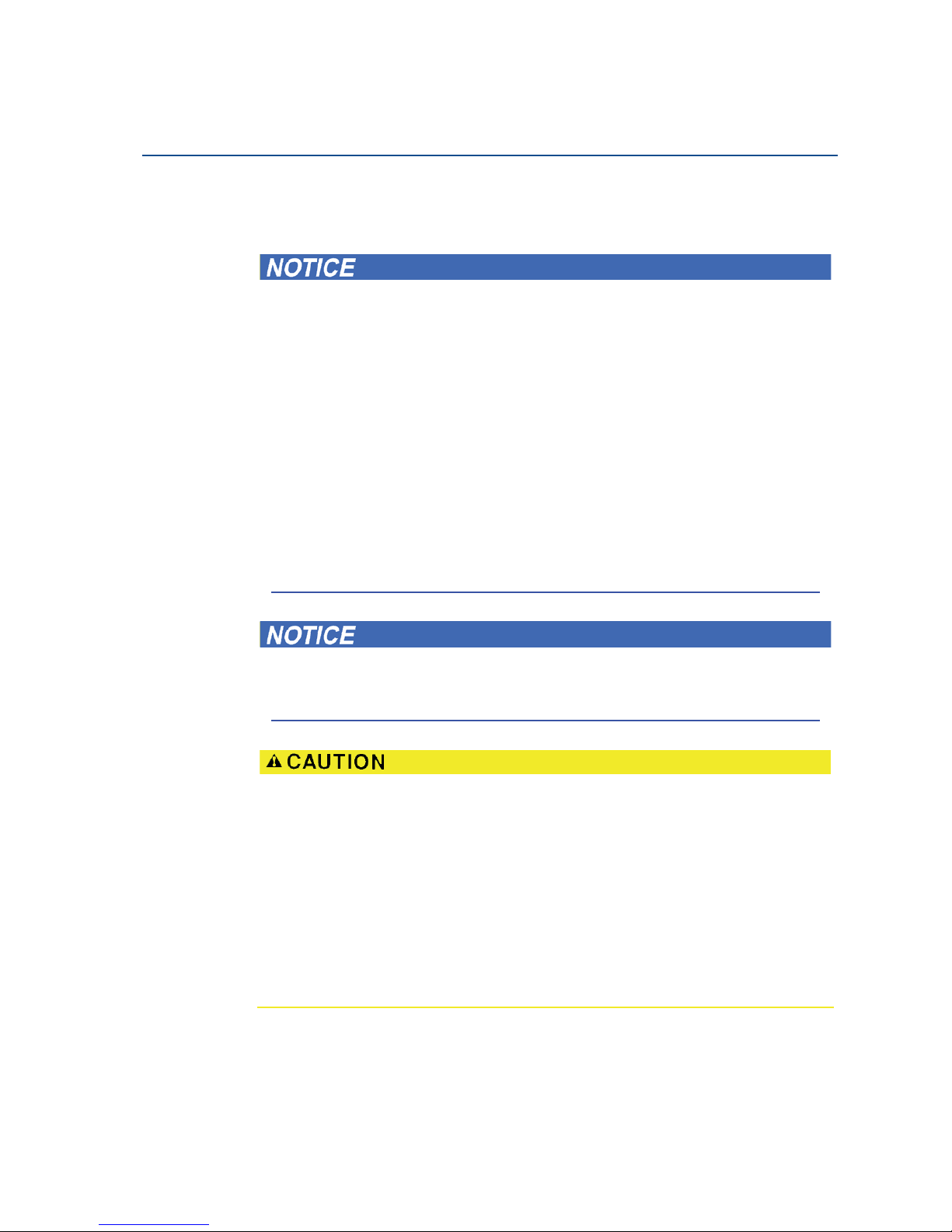
2.1 Theory of operation
The Rosemount 5400 Series Radar Transmitter is a smar t, two-wire continuous level transmitter.
A 5400 transmitter is installed at the top of the tank and emits short microwave pulses towards
the product surface in the tank. When a pulse reaches the surface, part of the energy is reflected
back to the antenna for subsequent processing by the transmitter electronics. The time
difference between the transmitted and reflected pulse is detected by a micro-processor and is
converted into a distance, which calculates the level.
The product level is related to the tank height and the measured distance by the following
expression:
Level = Tank Height - Distance
Figure 2-1. Measurement Principle for the Rosemount 5400 Series
Time
Level
Distance
Tan k H eig ht
Signal Amplitude
Radar Pulse
Page 20
8
Reference Manual
00809-0100-4026, Rev HA
Section 2: Transmitter Overview
November 2014
Tran smitter Over view
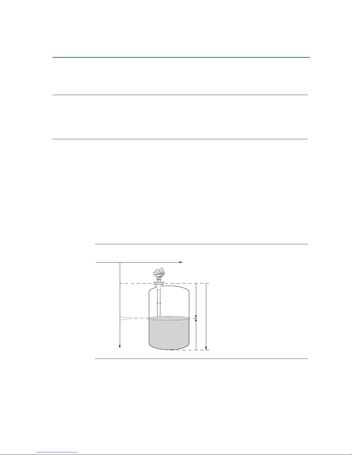
2.2 Application examples
Tanks, vessels, and containers with calm surfaces
Non-contacting radar can be used in less challenging applications,
such as storage and buffer tanks:
It is easy to mount, maintenance-free, and highly accurate
Gives precise monitoring and control of the process
Overfill and underfill detection
The Rosemount 5400 Series can be advantageous in risk reduction
systems:
Continuous measurement may reduce or simplify proof-tests
Multiple 5400s can be used in the same tank
Corrosives
Radar measurement is ideal for most corrosive products, such as
caustics, acids, solvents, and many other chemicals:
Does not contact the process product
Wide material offering such as PTFE, Alloy C-276 and Alloy 400
Works well in non-metallic tanks also
Sticky, viscous, and crystallizing products
The best-in-class Rosemount 5400 Series provides an accurate and
reliable level reading with difficult products, such as resins and
adhesives:
Non-contacting is best practice
Almost unaffected by coating and build-up because of the
uniquely designed condensation resistant antennas
Sludges and slurries
Applications like mud, pulp-stock, and lime slurries are ideal for
non-contacting measurement:
Immune to splashing and solids content
Unaffected by density changes
No re-calibration, no or little maintenance
Page 21

9
Reference Manual
00809-0100-4026, Rev HA
Section 2: Transmitter Overview
November 2014
Tra nsm itter Overview
Reactor vessels
The innovative design of the Rosemount 5400 Series makes it an
excellent choice for the most difficult applications, such as reactor
vessels:
Unique circular polarization provides greater mounting
flexibility – no tank wall clearance distance is needed
Direct measurement – independent of most variations in
process conditions, such as density, dielectric, vapor,
temperature, and pressure
Can handle turbulent conditions created by agitation,
top-filling, or process reaction
Mounting flexibility
The versatile Rosemount 5400 Series can be used in mounting
configurations other than standard nozzles:
Fits most existing pipes: 2-8 in. (50-200 mm)
Easy to isolate from the process – use a ball-valve
Still-pipes reduce the influence of foam, turbulence, and tank
obstructions. Ball-valves can be used on both still-pipes and
nozzles.
Underground tanks
The mounting flexibility of the Rosemount 5400 Series makes it an
excellent choice for many underground tanks:
Easy top-mounting
Can handle long narrow nozzles up to 6 ft (2 m) as long as they
are clean and smooth, and pipes
Unaffected by dirty products with solids content
Page 22

10
Reference Manual
00809-0100-4026, Rev HA
Section 2: Transmitter Overview
November 2014
Tran smitter Over view
2.3 System architecture
The Rosemount 5400 Series Radar Transmitter is loop-powered, and uses the same two wires
for power supply and output signal. The output is a 4-20 mA analog signal superimposed with a
digital HART
®
, FOUNDATION™ fieldbus or Modbus® signal.
By using the optional HART Tri-Loop™, the HART signal can be converted up to three additional
4-20 mA analog signals.
With the HART protocol, multidrop configuration is possible. In this case, communication is
restricted to digital, since current is fixed to the 4 mA minimum value.
The transmitter can be connected to a Rosemount 751 Field Signal Indicator, or it can be
equipped with an integral display.
The transmitter can easily be configured using a Field Communicator or a PC with the
Rosemount Radar Master (RRM) software. Rosemount 5400 Series transmitters can also be
configured with the AMS
®
Suite and DeltaV™ software, and other tools that support Electronic
Device Description Language (EDDL) functionality.
For HART communication, a minimum load resistance of 250 : within the loop is required.
Figure 2-2. HART System Architecture
Integral
Display
Rosemount 5400 Series
Radar Transmitter
Rosemount 751 Field
Signal Indicator
Field
Communicator
Tri -L oo p
3 x 4-20 mA
DCS
HART modem
RRM or
AMS Suite
Page 23

11
Reference Manual
00809-0100-4026, Rev HA
Section 2: Transmitter Overview
November 2014
Tra nsm itter Overview
Figure 2-3. FOUNDATION fieldbus System Architecture
The RS-485 Modbus version communicates by Modbus RTU, Modbus ASCII, and Level Master
Protocols.
HART communication is used for configuration via HART terminals, or tunneling via the RS-485.
Figure 2-4. RS-485 with Modbus Communication
FOUNDATION
fieldbus
Note
Intrinsically safe
installations may
allow fewer devices
per I.S. barrier due to
current limitations.
Host / DCS system (e.g. DeltaV)
Maintenance
Field
Communicator
Rosemo unt
5401
Rosemount
5402
Rosemo unt
5601
Fieldbus Modem
H1 - Low Speed Field Bus
6200 ft (1900 m) max
(depending upon cable
characteristics)
Configuration with RRM
(hooked up on Fieldbus
segment)
H2 - High Speed Field Bus
Rosemount 5400
Series Transmitter
HART
Modem
Power
Modbus, Levelmaster
Emulation / RS-485
Control
System
RS-232 / RS-485
Converter
PC
5400 Setup in RRM
PC
5400 Setup in RRM
through Tunneling
Field Communicator
Page 24

12
Reference Manual
00809-0100-4026, Rev HA
Section 2: Transmitter Overview
November 2014
Tran smitter Over view
2.4 Process characteristics
Dielectric constant
A key parameter for measurement performance is reflectivity. A high dielectric constant of the
media provides better reflection and enables a longer measuring range.
Foam
Rosemount 5400 Series Radar Transmitter measurement in foamy applications depends on the
foam properties; light and airy or dense and heavy, high or low dielectrics, etc. If the foam is
conductive and creamy, the transmitter may measure the surface of the foam. If the foam is less
conductive, the microwaves may penetrate the foam and measure the liquid surface.
Turbulence
A calm surface gives better reflection than a turbulent surface. For turbulent applications, the
maximum range of the radar transmitters is reduced. The range depends on the frequency, the
antenna size, the dielectric of the material, and the degree of turbulence. Consult Tables 2-2 and
2-3 on page 16 for the expected maximum range with the variables listed.
Temperature/pressure/density and vapor
Temperature, pressure, product density, and vapor generally have no impact on measurements.
Condensation
For applications where heavy condensation and vapors may occur, the low frequency version
Rosemount 5401 is recommended.
Tank characteristics
The conditions inside the tank have a significant impact on measurement performance. For
more information see “Vessel characteristics” on page 35.
Solid surface
The surface of solid materials is rarely flat or horizontal. The angle of repose, or surface
inclination, will change as the vessel fills and empties. There is often a lot of dust during the fill
cycle. The dielectric value of many solids is fairly low. See Table 2-1 on page 2-13 for common
solids characteristics.
For solids applications, the high frequency version Rosemount 5402 with 4 inch cone antenna is
available.
Page 25

13
Reference Manual
00809-0100-4026, Rev HA
Section 2: Transmitter Overview
November 2014
Tra nsm itter Overview
Table 2-1. Sample Solids Applications
(1)
Applications
Common characteristics
Particle size Vapor space
Dust or
Powder
Small
(<1 in.)
Larger
(>1 in.)
Dust
Steam or
Condensation
Wood chip bins Yes Yes Yes Yes Possible
Grain silo - small
kernel grains
Yes Yes No Yes No
Grain silo - large
kernel grains
No Yes No No No
Lime stone silo No Yes Yes Possible No
Cement - raw mill silo Yes Yes No Yes No
Cement - finished
product silo
Yes Yes No Yes No
Coal bin Yes Yes Yes Yes Yes
Saw dust Yes Yes No Yes No
High consistency pulp stock
No No No No Ye s
Alumina Yes Yes No Yes No
Salt No Yes Yes No No
(1) Air purging might be needed in dusty environments.
Page 26
14
Reference Manual
00809-0100-4026, Rev HA
Section 2: Transmitter Overview
November 2014
Tran smitter Over view
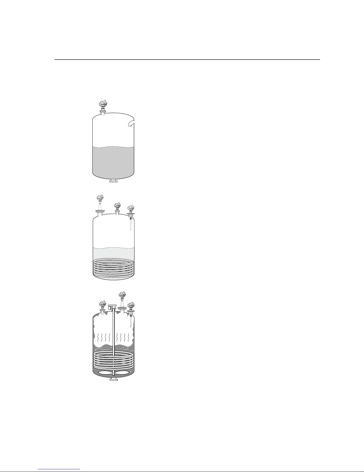
2.5 Components of the transmitter
The Rosemount 5400 Series Radar Transmitter is available with a die-cast aluminum or stainless
steel (SST) housing containing advanced electronics for signal processing.
The radar electronics produces an electromagnetic pulse that is emitted through the antenna.
There are different antenna types and sizes available for various applications.
The transmitter head has separate compartments for electronics and terminals, and can be
removed without opening the tank. The head has two entries for conduit/cable connections.
The tank connection consists of a Tank Seal and a flange (ANSI, EN (DIN) or JIS).
Figure 2-5. Transmitter Components
B
G
H
A
E
F
D
C
A. Display Panel
B. Cable Entry: ½" NPT.
Optional adapters: M20
C. Tank Seal
D. Flange
E. Terminal side
F. Cable Entry: ½" NPT.
Optional adapters: M20
G. Transmitter head with Radar electronics
H. Antenna
Page 27

15
Reference Manual
00809-0100-4026, Rev HA
Section 2: Transmitter Overview
November 2014
Tra nsm itter Overview
2.6 Antenna selection guide/measuring range
The measuring range depends on the microwave frequency, antenna size, the dielectric
constant (H
r
) of the liquid, and process conditions. A higher dielectric constant value produces a
stronger reflection. The figures in the tables below are guidelines for optimum performance.
Larger measuring ranges may be possible. For more information, contact your local Emerson
Process Management representative.
A. Oil, gasoline or other hydrocarbons, and petrochemicals (H
r
= 1.9-4.0). In pipes or with
ideal surface conditions, for some liquefied gases (H
r
= 1.4-4.0).
B. Alcohols, concentrated acids, organic solvents, oil/water mixtures, and acetone
(H
r
= 4.0-10.0).
C. Conductive liquids, e.g. water based solutions, dilute acids, and alkalis (H
r
> 10.0).
Table 2-2. Rosemount 5402, Maximum Recommended Measuring Range, ft (m)
High
frequency
antennas
Dielectric constant
(1)
(1) A. Oil, gasoline or other hydrocarbons, and petrochemicals (
H
r
= 1.9-4.0)
In pipes or with ideal surface conditions, for some liquefied gases (
H
r
= 1.4-4.0)
B. Alcohols, concentrated acids, organic solvents, oil/water mixtures, and acetone (
H
r
= 4.0-10.0)
C. Conductive liquids, e.g. water based solutions, dilute acids, and alkalis (
H
r
> 10.0)
A B C A B C A B C
2-in. Cone/
Process seal
33 (10) 49 (15) 66 (20) 82 (25) 115 (35) 115 (35) 9.8 (3) 20 (6) 33 (10)
3-in. Cone/
Process seal
49 (15) 66 (20) 98 (30) 82 (25) 115 (35) 115 (35) 13 (4) 30 (9) 39 (12)
4-in. Cone/
Process seal
66 (20) 82 (25) 115 (35) 82 (25) 115 (35) 115 (35) 23 (7) 39 (12) 49 (15)
Page 28
16
Reference Manual
00809-0100-4026, Rev HA
Section 2: Transmitter Overview
November 2014
Tran smitter Over view
Table 2-3. Rosemount 5401, Maximum Recommended Measuring Range, ft (m)
Low
Frequency
Antennas
Dielectric Constant
(1)
(1) a. Oil, gasoline or other hydrocarbons, and petrochemicals (
H
r
= 1.9-4.0)
In pipes or with ideal surface conditions, for some liquefied gases (
H
r
= 1.4-4.0)
b. Alcohols, concentrated acids, org anic solvents, oil/water mixtures, and acetone (
H
r
= 4.0-10.0)
c. Conductive liquids, e.g. water based solutions, dilute acids, and alkalis (
H
r
> 10.0)
a b c a b c a b c
3-in. Cone
(2)
(2) Pipe installations only. NA = Not Applicable.
NA NA NA 82 (25) 115 (35) 115 (35) NA NA NA
4-in. Cone /
Rod
(3)
(3) Pipe installations are not allowed with rod antennas.
23 (7) 39 (12) 49 (15) 82 (25) 115 (35) 115 (35) 13 (4) 26 (8) 39 (12)
6-in. Cone
43 (13) 66 (20) 82 (25) 82 (25) 115 (35) 115 (35) 20 (6) 33 (10) 46 (14)
8-in. Cone
66 (20) 82 (25) 115 (35) 82 (25) 115 (35) 115 (35) 26 (8) 39 (12) 52 (16)
Page 29
17
Reference Manual
00809-0100-4026, Rev HA
Section 2: Transmitter Overview
November 2014
Tra nsm itter Overview
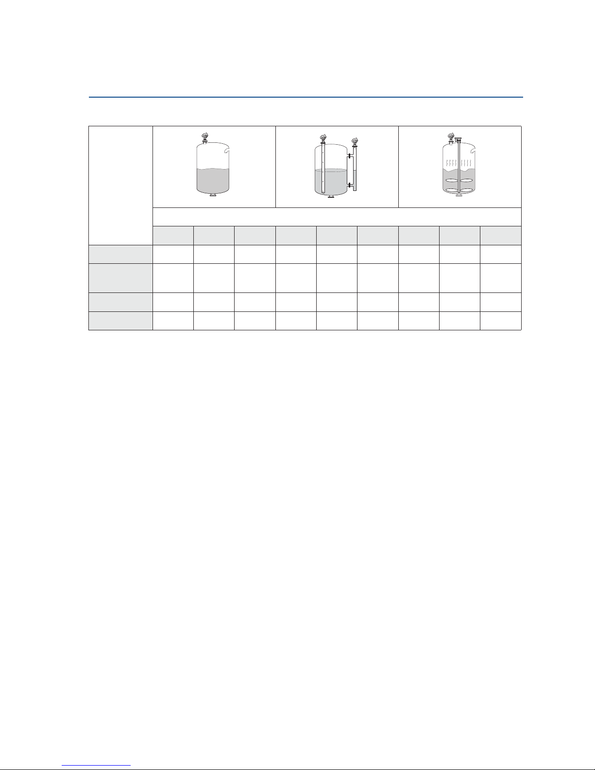
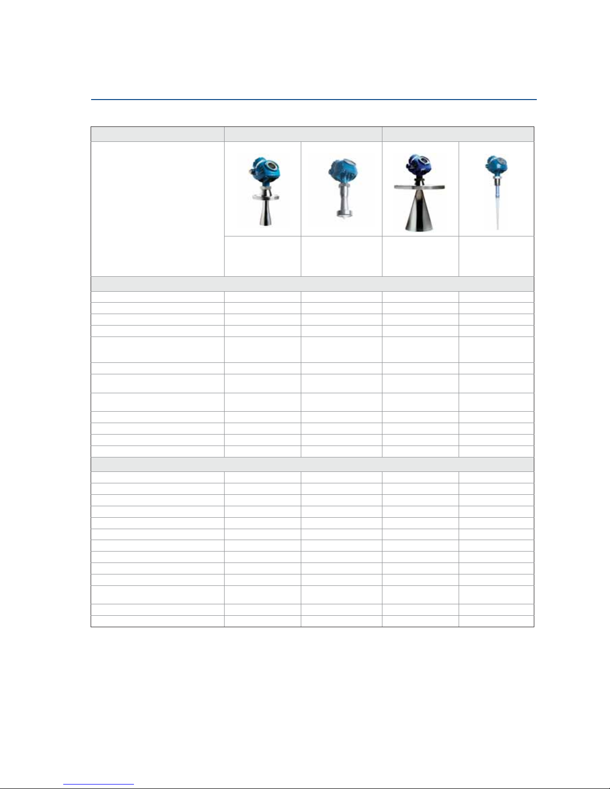
Table 2-4. Model and Antenna Guide
Model and antenna guide
5402 5401
This table gives guidelines on which
model and antenna to select, depending
on application.
G = Good
AD = Application Dependent (consult
your local Emerson Process
Management representative)
NR = Not Recommended
Cone (preferred) Process seal Cone (preferred) Rod
Best choice for a
broad range of
applications, free
propagation and pipe
installations.
Ideal for small tanks
and corrosive
applications. Also good
for heav y antenna
condensation/build-up.
Suitable for some
extreme process
conditions.
Suitable for small
process connections,
and corrosive
environmen t.
Tank considerations
Installation close to smooth tank wall G G G G
Multiple units on the same tank G G G G
Internal obstructions, directly in path
(1)
NR NR AD AD
Internal obstructions, avoidance
(1)
(1) The obstruction should not be within the radar beam. Preferred choices due to more narrow radar beam: Model 5402, and cone antenna.
G G NR NR
Beam angle 2” 19°
3” 14°
4” 9°
2” 19°
3” 14°
4” 9°
4” 37°
6” 23°
8” 17°
37°
Antenna extends below nozzle G G G G
Antenna recessed in smooth nozzle up to
6 ft (2 m)
GG NR
(2)
(2) If tall nozzle, use extended antenna.
NR
(3)
(3) The active part must protrude beneath the nozzle.
Antenna recessed in nozzle with
irregularities, such as bad welds
AD
(4)
(4) An e xtended cone antenna must be used.
AD AD
(4)
NR
(3)
Stilling well mounting G 2”- 4” pipe G 2”- 4” pipe G 3”- 8” pipe NR
Valves G G NR NR
Long ranges (>115’ / 35 m) NR NR NR NR
Cleanability of antenna AD G AD G
Process medium characteristics
Vapor (light, medium) G G G G
Vapor (heavy) NR AD G G
Condensing vapor/product build-up
(5)
(5) Build-up can often be avoided or reduced by using heat-tracing or cleaning arrangements.
AD G G AD
Boiling/Turbulent surface (low/medium) G G G G
Boiling/Turbulent surface (heav y) AD AD G
(6)
(6) Use a 6 or 8 in. (150-200 mm) cone antenna.
NR
Boiling/Turbulent surface (still-pipe) G G G NR
Foam
(7)
(7) Foam can either reflect, be invisible, or absorb the radar signal. Pipe mounting is advantageous since it reduces the foaming tendency.
NR NR AD AD
Foam (still-pipe)
(7)
GG GNR
Corrosive products (options available) G
(8)
(8) Other wetted material options include Alloy C-276 and Alloy 400. See the Rosemount 5400 Series Product Data Sheet (Document No. 00813-0100-4026) for details.
G
(8)
G
(8)
G
Materials with ver y low dielectric G G G AD
Changing density/dielectric/pH/
pressure/temperature
GG GG
Coating/viscous/crystallizing liquids G G G G
Solids, granules, powders G NR NR NR
Page 30

18
Reference Manual
00809-0100-4026, Rev HA
Section 2: Transmitter Overview
November 2014
Tran smitter Over view
Page 31

19
Reference Manual
00809-0100-4026, Rev HA
Section 3: Mechanical Installation
November 2014
Mechanical Installation
Section 3 Mechanical Installation
Safety messages . . . . . . . . . . . . . . . . . . . . . . . . . . . . . . . . . . . . . . . . . . . . . . . . . . . . . . . . . . . . page 19
Installation procedure . . . . . . . . . . . . . . . . . . . . . . . . . . . . . . . . . . . . . . . . . . . . . . . . . . . . . . . page 21
Mounting considerations . . . . . . . . . . . . . . . . . . . . . . . . . . . . . . . . . . . . . . . . . . . . . . . . . . . . page 22
Mounting . . . . . . . . . . . . . . . . . . . . . . . . . . . . . . . . . . . . . . . . . . . . . . . . . . . . . . . . . . . . . . . . . . page 36
3.1 Safety messages
Procedures and instructions in this section may require special precautions to ensure the safety
of the personnel performing the operations. Information that raises potential safety issues is
indicated by a warning symbol ( ). Refer to the following safety messages before performing
an operation preceded by this symbol.
Page 32

20
Reference Manual
00809-0100-4026, Rev HA
Section 3: Mechanical Installation
November 2014
Mechanical Installation
Failure to follow safe installation and service guidelines could result in death or
serious injury.
Make sure only qualified personnel perform installation or service.
Use the equipment only as specified in this manual. Failure to do so may impair the
protection provided by the equipment.
Any substitution of non-recognized spare parts may jeopardize safety. Repair, e.g.
substitution of components etc. may also jeopardize safety and is under no
circumstances allowed.
Process leaks could result in death or serious injury.
Make sure that the transmitter is handled carefully. If the Process Seal is damaged, gas
might escape from the tank if the transmitter head is removed from the antenna.
Explosions could result in death or serious injury.
Verify that the operating environment of the transmitter is consistent with the
appropriate hazardous locations specifications.
In an Explosion-proof/Flameproof installation, do not remove the transmitter cover
when power is applied to the unit.
Before connecting a HART
®
-
based communicator in an explosive atmosphere, make
sure the instruments in the loop are installed in accordance with intrinsically safe or
non-incendive field wiring practices.
Electrical shock can result in death or serious injury.
Avoid contact with the leads and terminals. High voltage that may be present on leads
can cause electrical shock.
Make sure the main power to the Rosemount 5400 Series transmitter is off and the
lines to any other external power source are disconnected or not powered while wiring
the transmitter.
Antennas with non-conducting surfaces.
Antennas with non-conducting surfaces (e.g. Rod antenna and Process Seal antenna)
may generate an ignition-capable level of electrostatic charge under extreme
conditions.
Therefore, when the antenna is used in a potentially explosive atmosphere,
appropriate measures must be taken to prevent electrostatic discharge.
Page 33

21
Reference Manual
00809-0100-4026, Rev HA
Section 3: Mechanical Installation
November 2014
Mechanical Installation
3.2 Installation procedure
Follow these steps for proper installation:
Review installation
considerations
(see page 22)
Mount the transmitter
(see page 36)
Wire the transmitter
(see page 43)
Make sure covers and
cable/conduit
connections are tight
Power up the
transmitter
Configure the
transmitter
(see page 73)
Veri fy me asureme nts
Ground the housing
(see page 46)
Page 34

22
Reference Manual
00809-0100-4026, Rev HA
Section 3: Mechanical Installation
November 2014
Mechanical Installation
3.3 Mounting considerations
Before installing a Rosemount 5400 Series transmitter, consider specific mounting
requirements, vessel, and process characteristics.
3.3.1 Mounting location
For optimal performance, the transmitter should be installed in locations with a clear and
unobstructed view of the level surface (A):
Filling inlets creating turbulence (B), and stationary metallic objects with horizontal
surfaces (C) should be kept outside the signal beam – see page 33 for beamwidth
information
Agitators with large horizontal blades may reduce the performance of the transmitter,
so install the transmitter in a location where this effect is minimized. Vertical or slanted
blades are often invisible to radar, but create turbulence (D)
Do not install the transmitter in the center of the tank (E)
Because of circular polarization, there is no clearance distance requirement from the
tank wall if it is flat and free of obstructions such as heating coils and ladders (F).
Usually, the optimal location is
1
/4 of the diameter from the tank wall
Note
Proper mounting position is important to consider.
Figure 3-1. Proper Mounting Position
The antenna is normally aligned vertically
(D) (A) (E) (B) (F) (C)
Page 35

23
Reference Manual
00809-0100-4026, Rev HA
Section 3: Mechanical Installation
November 2014
Mechanical Installation
A metal still-pipe can be used to avoid disturbing objects, turbulence, and foam (G)
Figure 3-2. Mounting in Still-Pipe
The walls in non-metallic tanks are invisible to the radar signal, so nearby objects
outside of the tank may be detected
Choose the largest possible antenna diameter for installation. A larger antenna
concentrates the radar beam, will be less susceptible to obstruction interference, and
assures maximum antenna gain
Multiple Rosemount 5400 Series transmitters can be used in the same tank without
interfering with each other (H)
Figure 3-3. Multiple Rosemount 5400 Series Transmitters in the Same Tank
(G)
(H)
Page 36

24
Reference Manual
00809-0100-4026, Rev HA
Section 3: Mechanical Installation
November 2014
Mechanical Installation
3.3.2 Special considerations in solids applications
The transmitter should be mounted as close to the center of the tank as possible, but
not in the center of the tank. A general practice is to mount the transmitter at
2
/3 tank
radius from the tank wall, see Figure 3-4.
Figure 3-4. Transmitter Location in Solids Applications
The radar signal must never be shaded by the inlet nor the injected product, see
Figure 3-5.
Figure 3-5. Install the Transmitter with a Clear and Unobstructed View
Page 37

25
Reference Manual
00809-0100-4026, Rev HA
Section 3: Mechanical Installation
November 2014
Mechanical Installation
3.3.3 Mounting in pipes
Still-pipe mounting is recommended for tanks with extremely turbulent surface conditions. All
cone antenna sizes for the Rosemount 5400 Series of transmitters can be used for Still-pipe
installations. The 3 in. (75 mm) antenna for the 5401 is designed for use in Still-pipes only. Rod
antennas are not recommended for Still-pipes.
When the transmitter is mounted on a Still-pipe, the inclination should be
within 1°. The gap between the antenna and the Still-pipe may be up to 0.2 in. (5 mm).
Figure 3-6. Mount the Transmitter Vertically
Recommendations for pipe installations
The pipe interior must be smooth
Not suitable for adhesive products
At least one hole is above the product surface
The hole diameter Ø should not exceed 10 % of the pipe diameter D
Holes should only be drilled on one side
Max. 0.2 in
(5 mm)
max. 1 °
Page 38

26
Reference Manual
00809-0100-4026, Rev HA
Section 3: Mechanical Installation
November 2014
Mechanical Installation
Figure 3-7. Recommended Hole Size for Pipe Installations
3.3.4 Installation considerations
Generally, the radar signal is unaffected by condensation and low pressure steam. If affected,
the lower microwave frequencies are less affected. The critical point is the tank penetration,
which acts as a cold spot, where the condensation will form. The radar antenna is located at this
cold spot.
If droplets of water build up on the antenna parts, the microwave signal may get partially or
even entirely blocked if the antenna is not designed for easy drip-off. Therefore, here it is
beneficial to use as large opening for the microwaves as possible, which is the main reason for
the oversized PTFE seal in the Rosemount 5400 Series Cone Antennas. An even better solution is
to use a Process Seal Antenna if the process pressure permits that.
To reduce the cold spot within the nozzle, it is always recommended to insulate the nozzle. By
doing so, the temperature in the nozzle will be the same as in the rest of the vessel and
condensation will thus be reduced. If the temperature in the tank is much higher than the
ambient temperature (i.e. tank is heated and located in a cold area), it might be necessary to
heat trace the nozzle in addition to the insulation.
Figure 3-8. Insulate Nozzle to Avoid Condensation
min. 6 in. (150 mm)
max. Ø: D/10.
D
Page 39

27
Reference Manual
00809-0100-4026, Rev HA
Section 3: Mechanical Installation
November 2014
Mechanical Installation
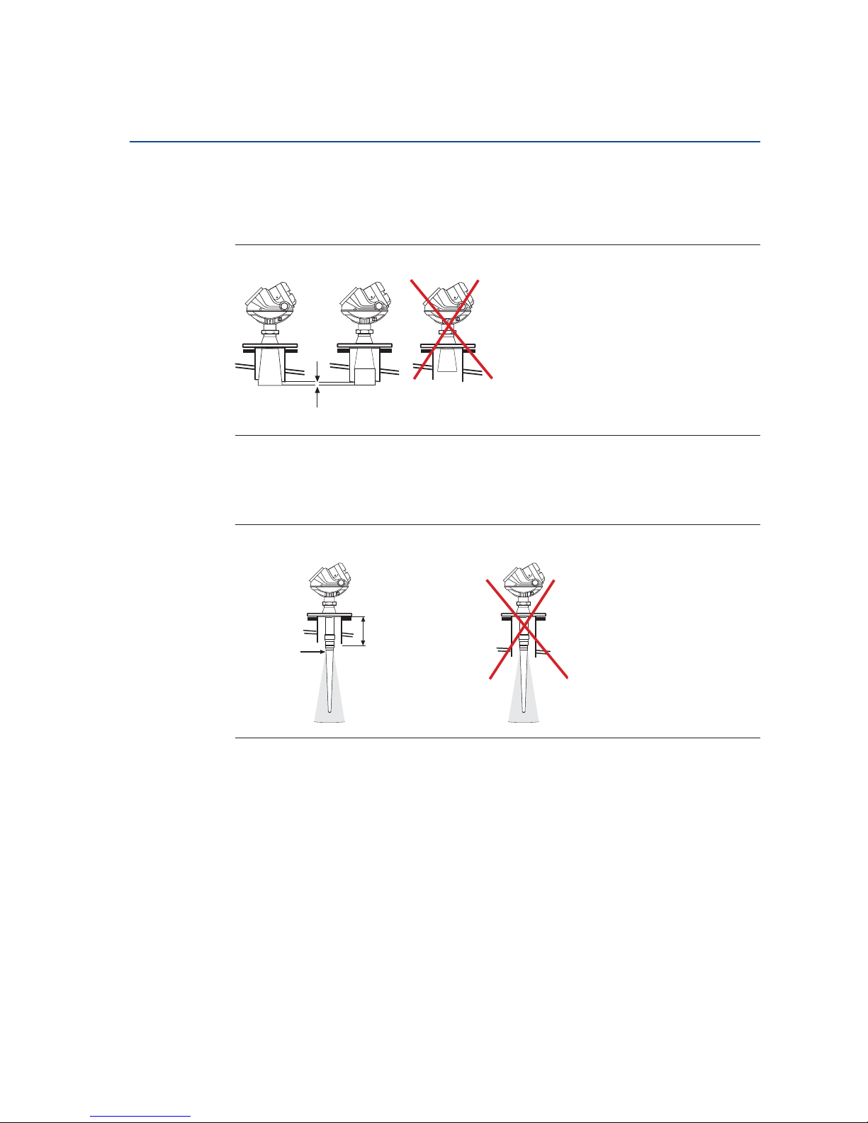
3.3.5 Nozzle considerations
Special considerations may have to be taken because of the nozzle, depending on the selection
of transmitter model and antenna.
5402 with cone antenna
The antenna can be recessed in smooth nozzles up to 6 ft (2 m). If the inside of the nozzle
contains disturbing objects, use the extended cone (I).
Figure 3-9. Nozzle Considerations for 5402 with Cone Antenna
5402 with process seal antenna
The antenna can be used on nozzles up to 6 ft (2 m), (J). Disturbing objects inside the nozzle (K)
may impact the measurement, and should therefore be avoided.
The flange on the tank should have a flat or raised face. Other tank flanges may be possible,
please consult your local Emerson Process Management representative for advice.
Figure 3-10. Nozzle Considerations for 5402 with Process Seal Antenna
Spray nozzle
(I)
Smooth nozzle
Bad weldings
(K) Bad welding
(J)
Page 40
28
Reference Manual
00809-0100-4026, Rev HA
Section 3: Mechanical Installation
November 2014
Mechanical Installation
5401 with cone antenna
The antenna should extend 0.4 in. (10 mm), or more, below the nozzle (L). If required, use the
extended cone solution.
Figure 3-11. Nozzle Considerations for 5401 with Cone Antenna
5401 with rod antenna
The active part of the rod antenna should protrude below the nozzle (M).
Figure 3-12. Nozzle Considerations for 5401 with Rod Antenna
Still-pipes in metallic materials
If used correctly, pipe measurement can be advantageous in many applications:
The 5402 is the preferred choice for smaller pipe diameters
Use the 5401 for larger pipe diameters (6-8 in./150-200 mm),
pipes with larger holes or slots, or for dirty/sticky media
Use cone or process seal antennas - not the rod antenna
The gap between the cone antenna and the still-pipe is limited to 0.2 in. (5 mm). If
required, order an oversized antenna and cut on location (N). Only applicable to 5401
cone antennas and cone antennas with wetted flange plate (i.e. straight antennas).
The inside of the chamber must be of a constant diameter
(L) 0.4 in. (10 mm) or more
Active part
starts here
(M)
Max. 4 or 10 in.
(100 or 250 mm)
for short and
long version
respectively
Page 41

29
Reference Manual
00809-0100-4026, Rev HA
Section 3: Mechanical Installation
November 2014
Mechanical Installation
Note
Match antenna size to the stilling well diameter.
Figure 3-13. Nozzle Considerations for Still-Pipes in Metallic Materials
Ball-valve installation
The Rosemount 5400 Series transmitter can be isolated from the process by using a valve:
The 5402 is the preferred choice for long nozzle measurement
Use the largest possible antenna
Use a full-port ball valve
Ensure there is no edge between the ball valve and the nozzle or stilling well, the inside
should be smooth
Valves can be combined with stilling wells
(N)
Max. 0.2 in.
(5 mm)
Page 42
30
Reference Manual
00809-0100-4026, Rev HA
Section 3: Mechanical Installation
November 2014
Mechanical Installation
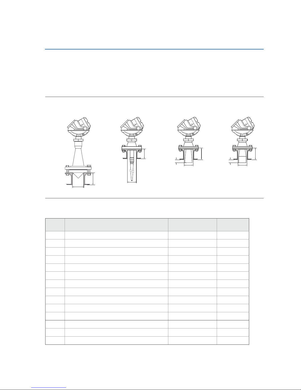
3.3.6 Nozzle recommendations and requirements
The Rosemount 5400 Series is mounted on a nozzle by using appropriate flanges. For best
performance, it is recommended that the nozzle meets the following recommendations for
height (L) and diameter:
Figure 3-14. Mounting of the Rosemount 5400 Series Transmitter
Table 3-1. Minimum Nozzle Diameter and Recommended Maximum Nozzle Height for Cone Antennas
Model Antenna / material
L
max
in. (mm)
Min. diameter
in. (mm)
5402
(1)
Cone 2 in. (50 mm) SST 6.1 (155) 2.2 (55)
Cone 3 in. (75 mm) SST 5.5 (140) 2.8 (72)
Cone 4 in. (100 mm) SST 8.5 (215) 3.8 (97)
Cone 2 in. (50 mm) Alloy C-276, Alloy 400 5.5 (140) 2.2 (55)
Cone 3 in. (75 mm) Alloy C-276, Alloy 400 6.5 (165) 2.8 (72)
Cone 4 in. (100 mm) Alloy C-276, Alloy 400 9.6 (240) 3.8 (97)
5401 Cone 3 in. (75 mm) SST Pipe installations only
Cone 4 in. (100 mm) SST 5.5 (140) 3.8 (97)
Cone 6 in. (150 mm) SST 6.9 (175) 5.7 (145)
Cone 8 in. (200 mm) SST 10.2 (260) 7.6 (193)
Cone 3 in. (75 mm) Alloy C-276, Alloy 400 Pipe installations only
Cone 4 in. (100 mm) Alloy C-276, Alloy 400 5.5 (140) 3.8 (97)
Cone 6 in. (150 mm) Alloy C-276, Alloy 400 6.9 (175) 5.7 (145)
Cone 8 in. (200 mm) Alloy C-276, Alloy 400 10.2 (260) 7.6 (193)
L
Minimum diameter
> 0.4 in.
(10 mm)
Minimum diameter
L
L
Minimum diameter
Minimum diameter
L
Process seal antenna Rod antenna Cone antenna Extended cone antenna
> 0.4 in.
(10 mm)
Page 43

31
Reference Manual
00809-0100-4026, Rev HA
Section 3: Mechanical Installation
November 2014
Mechanical Installation
Table 3-2. Minimum Nozzle Diameter and Maximum Nozzle Height for Rod Antennas
Table 3-3. Minimum Nozzle Diameter and Recommended Maximum Nozzle Height for Process Seal
Antennas
Table 3-4. Minimum Nozzle Diameter and Maximum Nozzle Height for Extended Cone Antennas
Install the transmitter as follows:
Align the antenna vertically.
Choose the largest antenna diameter possible. A larger receiving area concentrates the
radar beam and ensures maximum antenna gain. Increased antenna gain permits
greater margin for weak surface echoes. A larger antenna also results in smaller beam
angle and thereby, less interference from any internal structures in the tank.
For best measurement performance, the antenna should extend below the nozzle
0.4 in. (10 mm) or more.
For more information, see “Nozzle considerations” on page 27.
(1) For Rosemount 5402, the values for maximum nozzle height are recommendations. Note that the Rosemount 5402
with cone antenna can be recessed in smooth nozzles up to 6 ft (2m).
Model Antenna L
max
in. (mm) Min. diameter in. (mm)
5401
(1)
(1) For Rosemount 5401, the values for minimum nozzle diameter and maximum nozzle height are requirements.
Rod (short) 4.0 (100) 1.5 (38)
Rod (long) 10 (250) 1.5 (38)
Model Antenna L
max
in. (mm) Min. diameter in. (mm)
5402
(1)
(1) For Rosemount 5402, the values for maximum nozzle height are recommendations. Note that the Rosemount 5402
with process seal antenna can be recessed in smooth nozzles up to 6 ft (2m).
Process Seal 2 in. (50 mm) 19.7 (500) 2.0 (51)
Process Seal 3 in. (75 mm) 19.7 (500) 3.0 (77)
Process Seal 4 in. (100 mm) 19.7 (500) 4.0 (102)
Model Antenna
L
max
in. (mm)
Min. diameter
in. (mm)
5402
(1)
(1) For Rosemount 5402, the values for maximum nozzle height are recommendations.
Extended Cone Antenna, S3
(2)
(2) The extended cone antennas are available in 5 in. (125 mm) step increments from 10 to 50 in. (250-1250 mm). Consult
your local Emerson Process Management representative for more information. Expect long lead times for sizes other
than the 20 in. (500 mm) version.
20 in. (500 mm) See Tab l e 3 -1
5401
Extended Cone Antenna, S3
(2)
20 in. (500 mm) See Tab l e 3 -1
Page 44

32
Reference Manual
00809-0100-4026, Rev HA
Section 3: Mechanical Installation
November 2014
Mechanical Installation
3.3.7 Service space
For easy access to the transmitter, mount it with sufficient service space.
There is no requirement on clearance distance from the tank wall, provided it is flat and free of
obstructions such as heating coils and ladders. The optimal location is often
1
/4 of the tank
diameter.
Figure 3-15. Service Space Recommendations
Service space Antenna type Distance in. (mm)
A Cone, rod, process seal 20 (500)
B
Cone, rod 24 (600)
Process seal 33 (850)
Inclination Antenna type Maximum angle
CCone, rod, process seal3°
A
B
C
Rod antenna Cone antenna
A
B
C
C
B
A
Process seal antenna
Page 45

33
Reference Manual
00809-0100-4026, Rev HA
Section 3: Mechanical Installation
November 2014
Mechanical Installation
3.3.8 Beamwidth
The following recommendations should be considered when mounting the transmitter:
The transmitter should be mounted with as few internal structures as possible within
the beam angle
The flat tank wall can be located within the antenna beam angle if there is a minimum
distance from the transmitter to the tank wall (see Figure 3-15 for preferred
installation)
Figure 3-16. Beamwidth at Various Distances from the Flange
Table 3-5. Beamwidth for the Rosemount 5402 Model (in ft [m])
Distance
Antenna
2 in. (DN 50) cone/
process seal
3 in. (DN 80) cone/
process seal
4 in. (DN 100) cone/
process seal
16 ft (5 m) 4.9 (1.5) 3.3 (1.0) 3.3 (1.0)
33 ft (10 m) 9.8 (3.0) 6.6 (2.0) 4.9 (1.5)
49 ft (15 m) 14.8 (4.5) 9.8 (3.0) 8.2 (2.5)
66 ft (20 m) 19.7 (6.0) 13.1 (4.0) 9.8 (3.0)
Distance
5401
(low frequency)
5402
(high frequency)
16 ft (5 m)
33 ft (10 m)
49 ft (15 m)
66 ft (20 m)
Beamwidth
Page 46

34
Reference Manual
00809-0100-4026, Rev HA
Section 3: Mechanical Installation
November 2014
Mechanical Installation
Table 3-6. Beamwidth for the Rosemount 5401 Model (in ft [m])
Figure 3-17. Beam Angle
Table 3-7. Beam Angle for the Rosemount 5402
Table 3-8. Beam Angle for the Rosemount 5401
Distance
Antenna
4 in. (DN 100)
cone /rod
6 in. (DN 150)
cone
8 in. (DN 200)
cone
16 ft (5 m) 9.8 (3..0) 6.6 (2.0) 4.9 (1.5)
33 ft (10 m) 21.3 (6.5) 13.1 (4.0) 9.8 (3.0)
49 ft (15 m) 32.8 (10) 19.7 (6.0) 14.8 (4.5)
66 ft (20 m) 41 (12.5) 26.2 (8.0) 19.7 (6.0)
Antenna Beam angle
2 in. (50 mm) cone / process seal 19°
3 in. (75 mm) cone / process seal 14°
4 in. (100 mm) cone / process seal, rod 9°
Antenna Beam angle
3 in. (75 mm) cone Pipe installations only
4 in. (100 mm) cone / rod 37°
6 in. (150 mm) cone 23°
8 in. (200 mm) cone 17°
Beam angle
Page 47

35
Reference Manual
00809-0100-4026, Rev HA
Section 3: Mechanical Installation
November 2014
Mechanical Installation
3.3.9 Vessel characteristics
Heating coils, agitators and other objects in the tank may lead to disturbing echoes and noise in
the measurement signal. Vertical structures cause minimal effect since the radar signal is
scattered rather than directed back to the antenna.
The shape of the tank bottom affects the measurement signal when the product surface is close
to the tank bottom. The Rosemount 5400 Series has built-in functions which optimize
measurement performance for various bottom shapes (see “Tank type and tank bottom type”
on page 76).
3.3.10 Disturbing objects
The Rosemount 5400 Series transmitter should be mounted so that objects such as heating
coils, ladders, etc. are not in the radar signal path. These objects may cause false echoes
resulting in reduced measurement performance. However, the transmitter has built-in functions
designed to reduce the influence from disturbing objects where such objects cannot be totally
avoided.
The Rosemount 5402 has a narrower radar beam that is particularly suitable in installations with
tall or narrow nozzles, or nozzles close to the tank wall. It may also be used to avoid disturbing
objects in the tank.
3.3.11 Valves
The Rosemount 5400 Series transmitter can be isolated from the process by using a valve:
Use a full-port ball valve.
The 5402 is the required and the Process Seal Antenna is the preferred choice, since it
does not require a spool piece. The cone antenna can also be used.
Ensure there is no edge between the ball valve and the nozzle/pipe, the inside should
be smooth.
Valves can be combined with stilling wells.
Page 48

36
Reference Manual
00809-0100-4026, Rev HA
Section 3: Mechanical Installation
November 2014
Mechanical Installation
3.4 Mounting
Mount the transmitter on a nozzle on top of the tank making sure only qualified personnel
perform the installation.
The transmitter housing must not be opened.
If the transmitter housing must be removed for service, make sure the PTFE sealing is carefully
protected against dust and water.
3.4.1 Cone antenna flange connection
Figure 3-18. Mounting the Rosemount 5400 with Cone Antenna and Flange
1. Place a gasket on top of the tank flange.
2. Lower the transmitter with antenna and flange into the tank nozzle.
3. Tighten the bolts and nuts with sufficient torque for the flange and gasket choice.
A
C
H
F
I
G
D
J
E
B
A. Transmitter housing
B. Nut, 40 Nm (30 Lbft)
C. Bolt
D. Nut
E. Locking screw
F. F la nge
G. Cone antenna
H. Gasket
I. Tank flange
J. Nozzle
Page 49
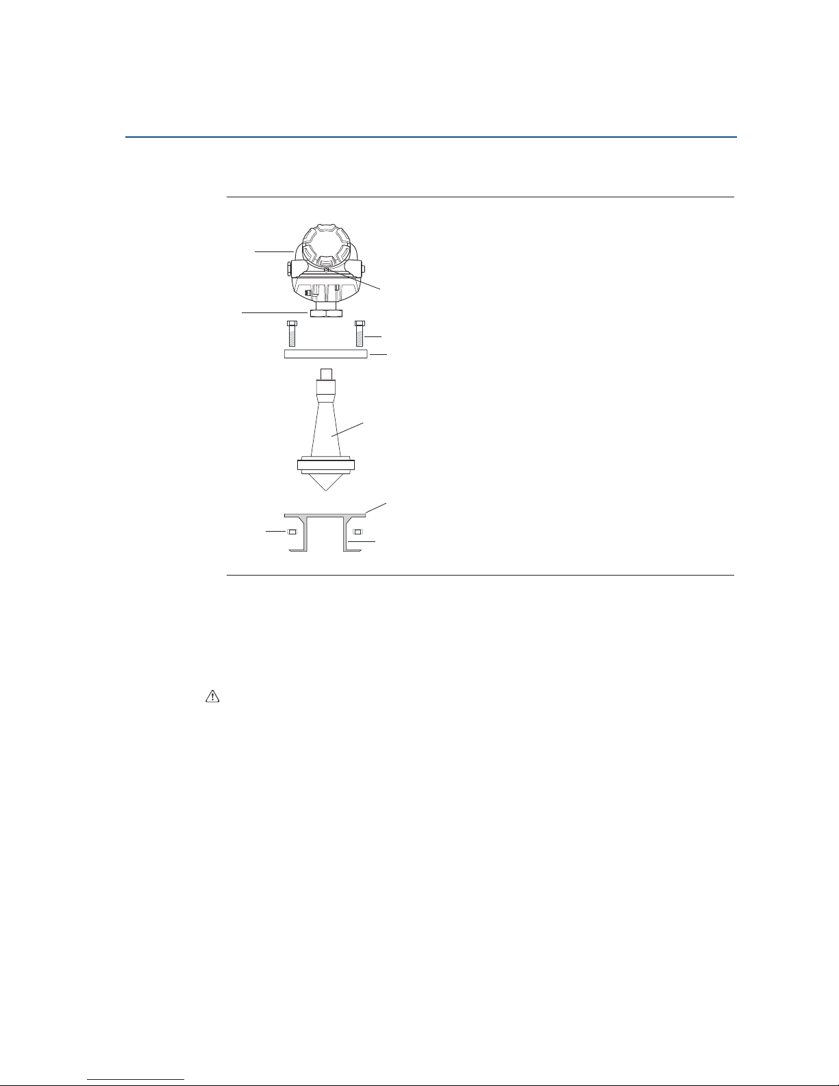
37
Reference Manual
00809-0100-4026, Rev HA
Section 3: Mechanical Installation
November 2014
Mechanical Installation
3.4.2 Process seal antenna
(1)
Figure 3-19. Mounting the Rosemount 5400 with Process Seal and Flange
1. Place the antenna on top of the nozzle.
2. Mount the flange and tighten the bolts cross-wise. For torque information,
see Ta bl e 3 -9 .
3. Mount the transmitter head and tighten the nut to 40 Nm (30 Lbft).
4. Re-tighten the flange bolts after 24 hours.
(1) The mounting information applies to the updated Process Seal antenna design, released in February 2012. Antennas manufactured before
this date have wetted O-rings and require a different installation procedure. For detailed information on the updated Process Seal antenna,
see the Rosemount 5400 Series Reference Manual - Supplementary Information for Process Seal Antennas Manual Supplement (Document
No. 00809-0700-4026).
E
F
A
B
D
G
H
I
C
A. Transmitter housing
B. Nut, 40 Nm (30 Lbft)
C. Nut
D. Locking screw (ATEX)
E. Bolt
F. F la nge
G. Process Seal antenna
H. Tank flange
I. Nozzle
Page 50

38
Reference Manual
00809-0100-4026, Rev HA
Section 3: Mechanical Installation
November 2014
Mechanical Installation
Table 3-9. Tightening Torque for Process Seal Flanges
3.4.3 Rod antenna threaded connection
Figure 3-20. Mounting the Rosemount 5400 with Rod Antenna and Threaded Tank
Connection
1. Lower the transmitter and antenna into the tank.
2. Turn the transmitter until it is properly secured in the process connection.
3. Make sure the cable entries and display face the right direction.
Note
Tank connections with NPT threads require a sealant for pressure-tight joints.
Flange Tor que (Nm) Torq ue (Lb ft)
2 in. (50 mm), 150 lb. 40 30
2 in. (50 mm), 300 lb. 40 30
3 in. (75 mm), 150 lb. 60 44
3 in. (75 mm), 300 lb. 60 44
4 in. (100 mm), 150 lb. 50 37
4 in. (100 mm), 300 lb. 50 37
DN 50 PN 40 40 30
DN 80 PN 40 60 44
DN 100 PN 16 50 37
DN 100 PN 40 50 37
50A 10K 40 30
80A 10K 60 44
100A 10K 50 37
150A 10K 50 37
A. Transmitter housing
B. Nut, 60 Nm (44 Lbft)
C. Locking screw (ATEX)
D. Sealant threads
E. Rod antenna
E
D
C
A
B
Page 51

39
Reference Manual
00809-0100-4026, Rev HA
Section 3: Mechanical Installation
November 2014
Mechanical Installation
3.4.4 Rod antenna flanged connection
Figure 3-21. Mounting the Rosemount 5400 with Rod Antenna and Flange
1. Place a gasket on top of the tank flange
(1)
. The gasket thickness and material must be
suitable for the process.
2. Lower the transmitter with antenna and flange into the tank nozzle.
3. Tighten the bolts and nuts with sufficient torque for the flange and gasket choice.
(1) Gasket is optional for the All-PFA version of the rod antenna.
C
F
H
J
G
A
B
D
E
I
A. Transmitter housing
B. Bolt
C. Gasket (optional for the All PFA version)
D.Nut
E. Locking screw (ATEX)
F. F la nge
G. PFA plate (only All PFA version, 1R, 2R)
H. Tank flange
I. Nozzle
J. Rod antenna
Page 52

40
Reference Manual
00809-0100-4026, Rev HA
Section 3: Mechanical Installation
November 2014
Mechanical Installation
3.4.5 Tri-Clamp™ tank connection
Figure 3-22. Mounting the Rosemount 5400 using a Tri-Clamp
1. Place a gasket on top of the tank flange.
2. Lower the transmitter and antenna into the tank.
3. Fasten the Tri-Clamp to the tank with a clamp.
4. To rotate the transmitter housing, loosen the nut.
5. Rotate the transmitter housing so the cable entries / display face the desired direction.
6. Tighten the nut.
C
B
A
D
E
F
A. Nut
B. Rod antenna
C. Gasket
D. Tank connection
E. Tri-Clamp
F. Clamp
Page 53

41
Reference Manual
00809-0100-4026, Rev HA
Section 3: Mechanical Installation
November 2014
Mechanical Installation
3.4.6 Bracket mounting on wall
Figure 3-23. Bracket Mounting the Rosemount 5400, on Wall
1. Mount the bracket directly to the wall with screws suitable for the purpose.
2. Mount the transmitter with antenna to the bracket, then secure the installation with
the three supplied screws.
A
C
B
A. Transmitter housing
B. Antenna
C. Bracket
Page 54

42
Reference Manual
00809-0100-4026, Rev HA
Section 3: Mechanical Installation
November 2014
Mechanical Installation
3.4.7 Bracket mounting on pipe
Figure 3-24. Bracket Mounting the Rosemount 5400, on Pipe
1. Put the two U-bolts through the holes of the bracket. Holes are available for both
vertical and horizontal pipe mounting.
2. Put the clamping brackets on the U-bolts and around the pipe.
3. Fasten the bracket to the pipe with the four supplied nuts.
4. Mount the transmitter with antenna to the bracket, and secure with the three supplied
screws.
C
G
E
B
A
D
F
A. U-bolts
B. Bracket
C. Clamping bracket
D. Screws
E. Transmitter housing
F. S cr ew
G. Antenna
Page 55

43
Reference Manual
00809-0100-4026, Rev HA
Section 4: Electrical Installation
November 2014
Electrical Installation
Section 4 Electrical Installation
Safety messages . . . . . . . . . . . . . . . . . . . . . . . . . . . . . . . . . . . . . . . . . . . . . . . . . . . . . . . . . . . . page 43
Wiring and power supply requirements . . . . . . . . . . . . . . . . . . . . . . . . . . . . . . . . . . . . . . . . page 44
Cable/conduit entries . . . . . . . . . . . . . . . . . . . . . . . . . . . . . . . . . . . . . . . . . . . . . . . . . . . . . . . page 45
Grounding . . . . . . . . . . . . . . . . . . . . . . . . . . . . . . . . . . . . . . . . . . . . . . . . . . . . . . . . . . . . . . . . . page 46
Cable selection . . . . . . . . . . . . . . . . . . . . . . . . . . . . . . . . . . . . . . . . . . . . . . . . . . . . . . . . . . . . . page 46
Hazardous areas . . . . . . . . . . . . . . . . . . . . . . . . . . . . . . . . . . . . . . . . . . . . . . . . . . . . . . . . . . . . page 47
External circuit breaker . . . . . . . . . . . . . . . . . . . . . . . . . . . . . . . . . . . . . . . . . . . . . . . . . . . . . . page 47
HART . . . . . . . . . . . . . . . . . . . . . . . . . . . . . . . . . . . . . . . . . . . . . . . . . . . . . . . . . . . . . . . . . . . . . . page 49
F
OUNDATION fieldbus . . . . . . . . . . . . . . . . . . . . . . . . . . . . . . . . . . . . . . . . . . . . . . . . . . . . . . . . . page 55
HART to Modbus Converter (HMC) . . . . . . . . . . . . . . . . . . . . . . . . . . . . . . . . . . . . . . . . . . . . page 60
Establish HART communication . . . . . . . . . . . . . . . . . . . . . . . . . . . . . . . . . . . . . . . . . . . . . . . page 66
Optional devices . . . . . . . . . . . . . . . . . . . . . . . . . . . . . . . . . . . . . . . . . . . . . . . . . . . . . . . . . . . . page 69
4.1 Safety messages
Procedures and instructions in this section may require special precautions to ensure the safety
of the personnel performing the operations. Information that raises potential safety issues is
indicated by a warning symbol ( ). Refer to the following safety messages before performing
an operation preceded by this symbol.
Page 56

44
Reference Manual
00809-0100-4026, Rev HA
Section 4: Electrical Installation
November 2014
Electrical Installation
Additional warnings or restrictions may apply depending on type of Hazardous approval. See
Appendix B: Product Certifications for details.
4.2 Wiring and power supply requirements
Wiring and power supply requirements can be dependent upon the approval certification. As
with all F
OUNDATION™ fieldbus requirements, a conditioned power supply and terminating
resistors are required for proper operation.
Failure to follow safe installation and service guidelines could result in death or
serious injury.
Make sure only qualified personnel perform installation or service.
Use the equipment only as specified in this manual. Failure to do so may impair the
protection provided by the equipment.
Any substitution of non-recognized spare parts may jeopardize safety. Repair, e.g.
substitution of components etc. may also jeopardize safety and is under no
circumstances allowed.
Do not perform any service other than those contained in this manual unless you are
qualified.
Process leaks could result in death or serious injury.
Make sure that the transmitter is handled carefully. If the process seal is damaged, gas
might escape from the tank if the transmitter head is removed from the antenna.
Explosions could result in death or serious injury.
Verify that the operating environment of the transmitter is consistent with the
appropriate hazardous locations specifications.
In an Explosion-proof/Flameproof installation, do not remove the transmitter cover
when power is applied to the unit.
Before connecting a HART
®
-
based communicator in an explosive atmosphere, make
sure the instruments in the loop are installed in accordance with intrinsically safe or
non-incendive field wiring practices.
Electrical shock can result in death or serious injury.
Avoid contact with the leads and terminals. High voltage that may be present on leads
can cause electrical shock.
Make sure the main power to the Rosemount 5400 Series transmitter is off and the
lines to any other external power source are disconnected or not powered while wiring
the transmitter.
High voltage that may be present on leads could cause electrical shock.
Avoid contact with leads and terminals.
Make sure the main power to the Rosemount 5400 transmitter is off and the lines to
any other external power source are disconnected or not powered while wiring the
gauge.
Antennas with non-conducting surfaces.
Antennas with non-conducting surfaces (e.g. rod antenna and process seal antenna)
may generate an ignition-capable level of electrostatic charge under extreme
conditions.
Therefore, when the antenna is used in a potentially explosive atmosphere,
appropriate measures must be taken to prevent electrostatic discharge.
Page 57

45
Reference Manual
00809-0100-4026, Rev HA
Section 4: Electrical Installation
November 2014
Electrical Installation
4.3 Cable/conduit entries
The electronics housing has two entries with ½ - 14 NPT threads. Optional M20×1.5 adapters
are also available. The connections shall be according to national, local, and plant electrical
codes.
Properly seal unused ports to prevent moisture or other contamination from entering the
terminal compartment of the electronics housing. Install wiring with a drip loop with the
bottom of the loop lower than the cable/conduit entry.
Figure 4-1. Cable Entries
Note
Use the enclosed metal plug to seal the unused port. The temporary orange plastic plugs used
at delivery are not sufficient seals! Failure to use the metal plug to seal the unused port
invalidates product certification.
4.3.1 Conduit electrical connector wiring (using minifast®)
For wiring details, refer to pin-out drawing and the cordset manufacturer’s installation
instructions.
Figure 4-2. Quick Connect Housing Pin-Out
For Rosemount 5400 Series transmitters with conduit electrical connector M, refer to the
cordset manufacturer’s installation instructions for wiring details.
Remove the orange protective plastic plugs, used for transportation.
Seal any unused port with the enclosed metal plug.
Cable Entry
(see
Figure
2-5 on
page 14
)
Cable Entry (see
Figure 2-5 on
page 14)
“+”
“-”
No connection
Ground
Page 58

46
Reference Manual
00809-0100-4026, Rev HA
Section 4: Electrical Installation
November 2014
Electrical Installation
4.4 Grounding
When wiring the transmitters, the grounding should be completed such that:
The loop is grounded at the power supply.
When transmitters are installed on metal tanks, ensure there is a metal-to-metal
connection between the device and the tank.
If the tank is non-metallic, the housing must be grounded to an earth ground that is
separate from the power supply. The external ground terminal may be used for this
purpose.
If the tank is cathodically protected, the housing must be grounded to an earth ground
that is outside of the cathodic protection system ground. Use the external terminal for
this purpose.
When transient protection terminal block is used, the ground wire should be separate from the
signal wire. Use the external ground terminal.
Make sure grounding is done (including IS ground inside Terminal compartment) according to
Hazardous Locations Certifications, national and local electrical codes.
The most effective transmitter housing grounding method is a direct connection to earth
ground with minimal (< 1 :) impedance.
Note
Grounding the transmitter housing using the threaded conduit connection may not provide a
sufficient ground. The transient protection terminal block will not provide transient protection
unless the transmitter housing is properly grounded. Use the above guidelines to ground the
transmitter housing. Do not run transient protection ground wire with signal wiring; the ground
wire may carry excessive current if a lightning strike occurs.
Note
After installation and commissioning, make sure that no ground currents exist from high
ground potential differences in the installation.
4.5 Cable selection
Use shielded twisted pair wiring for the Rosemount 5400 Series. The cables must be suitable for
the supply voltage and approved for use in hazardous areas, where applicable. For instance, in
the U.S., explosion-proof conduits must be used in the vicinity of the vessel. For the ATEX
flameproof approval version of the Rosemount 5400 Series, suitable conduits with sealing
device or flameproof cable glands must be used depending on local requirements.
Use 18 AWG to 12 AWG wiring to minimize the voltage drop to the transmitter.
For Modbus
®
units (RS-485 bus), the following rules apply:
2 cables are used for communication: 24 AWG shielded twisted pair wiring is
recommended to get an impedance of 120 :
2 cables are used for power: AWG 16-18 cables must be used
Page 59

47
Reference Manual
00809-0100-4026, Rev HA
Section 4: Electrical Installation
November 2014
Electrical Installation
Note
Avoid running instrument cable next to power cables in cable trays or near heavy electrical
equipment.
It is important that the instrument cable shield be:
- trimmed close and insulated from touching the transmitter housing
- continuously connected throughout the segment
- connected to a good earth ground at the power supply end
4.6 Hazardous areas
When the Rosemount 5400 Series transmitter is installed in a hazardous area, all national and
local regulations and specifications in applicable certificates must be observed.
4.7 External circuit breaker
For compliance with Low Voltage Directive 2006/95/EC, an external circuit breaker should be
installed.
4.7.1 Connecting the transmitter
The Rosemount 5400 Series accepts power supplies ranging from 16 Vdc to 42.4 Vdc. It uses
4-20 mA power superimposed with a HART signal.
To connect the transmitter:
1. Verify that the power supply is disconnected.
2. Remove the terminal block cover (see Figure 4-3).
3. Pull the cable through the cable gland/conduit. For explosion-proof/ flameproof
installations, only use cable glands or conduit entry devices certified explosion-proof or
flameproof. Install the wiring with a drip loop where the bottom of the loop must be
lower than the cable/conduit entry.
4. To connect the wires, see the illustrations on the following pages.
5. Remove the orange protective plastic plugs used for transportation. Seal any unused
port with the enclosed metal plug.
6. Mount the cover and make sure it is fully engaged to meet explosion-proof
requirements (adapters are required if M20 glands are used).
For ATEX, IECEx, NEPSI, INMETRO, and TIIS installations, lock the cover with the locking
screw.
7. Connect the power supply.
Note
Use PTFE tape or other sealant at the NPT threads in the cable entries.
Page 60

48
Reference Manual
00809-0100-4026, Rev HA
Section 4: Electrical Installation
November 2014
Electrical Installation
Figure 4-3. Terminal Compartment and External Ground Screw
Note
Remove the orange, protective, plastic plugs, used for transportation. Seal any unused port with
the enclosed metal plug.
Cable entry
NPT ½ in.-14, or
M20 X 1.5 adapter
External ground
screw
Blind plug
Supplied for unused
conduit opening.
Terminals for signal
and power supply
Cable entry
NPT ½ in.-14,
or M20 X 1.5
adapter
Locking screw
Internal ground
screw
Page 61

49
Reference Manual
00809-0100-4026, Rev HA
Section 4: Electrical Installation
November 2014
Electrical Installation
4.8 HART
4.8.1 Power requirements
The Rosemount 5400 Series transmitter operates with a power supply ranging from
16 - 42.4 Vdc (16 - 30 Vdc in IS applications, 20 - 42.4 Vdc in explosion-proof / flameproof
applications and in non-sparking / energy-limited applications).
All configuration tools for HART communication, such as the Field Communicator and
Rosemount Radar Master, require a minimum load resistance (R
L
) of 250 : within the loop in
order to function properly.
Terminals in the transmitter housing provide connections for signal wiring. The Rosemount
5400 Series operates with the following power supplies:
Table 4-1. Minimum Input Voltage (U
I
) at Different Currents
4.8.2 Load limitations
Maximum load resistance (R) is determined by the voltage level of the external power supply
(U
E
), as described by:
Figure 4-4. Non-Hazardous Installations, and Non-Sparking / Energy-Limited Power
Supply
Hazardous approval
Current
3.75 mA 21.75 mA
Minimum input voltage (UI)
Non-Hazardous Installations and
Intrinsically Safe Installations
16 Vdc 11 Vdc
Explosion-proof / Flameproof
Installations
20 Vdc 15.5 Vdc
10 2016 30
200
400
600
800
1000
1200
1400
40 50
42.424
586
1387
External Power Supply Voltage UE(V)
Maximum Load Resistance R(
W)
Operating
region
Page 62

50
Reference Manual
00809-0100-4026, Rev HA
Section 4: Electrical Installation
November 2014
Electrical Installation
Figure 4-5. Intrinsically Safe Installations
Figure 4-6. Explosion-Proof / Flameproof Installations
Note
For flameproof/explosion-proof installations, the diagram is only valid if the HART load
resistance is at the + side and if the - side is grounded. Otherwise, the load resistance value is
limited to 435 :.
Note
Rosemount 5400 Series Transmitters with flameproof/explosion-proof output have a built-in
barrier; no external barrier needed.
External Power Supply Voltage UE(V)
Maximum Load Resistance R(
W)
Operating
region
10 20 30
200
400
600
800
1000
1200
1400
40 50
24 42.4
1148
348
External Power Supply Voltage UE(V)
Maximum Load Resistance R(
W)
Operating
region
Page 63

51
Reference Manual
00809-0100-4026, Rev HA
Section 4: Electrical Installation
November 2014
Electrical Installation
4.8.3 Non-intrinsically safe power supply
With a non-intrinsically safe power supply in non-hazardous installations or explosion-proof/flameproof installations, wire the transmitter as shown in Figure 4-7.
Note
Make sure the power supply is off when connecting the transmitter.
Figure 4-7. Wiring for Non-Intrinsically Safe Power Supply (HART)
The Field Communicator and the HART modem require a minimum load resistance of 250 :
within the loop to function properly.
Note
The diagram is valid only if the HART load resistance is at the + side and if the - side is grounded,
otherwise the load resistance value is limited to 435 :.
Note
For explosion-proof/flameproof installations make sure the transmitter is grounded to the I.S.
ground terminal inside the terminal compartment in accordance with national and local
electrical codes.
Rosemount 5400 Series Radar
Level Transmitter
Field Communicator
HART
modem
Load Resistance 250 W
Power
Supply
PC
Page 64

52
Reference Manual
00809-0100-4026, Rev HA
Section 4: Electrical Installation
November 2014
Electrical Installation
4.8.4 Intrinsically safe power supply
With an intrinsically safe power supply, wire the transmitter as shown in Figure 4-8.
Note
Make sure the instruments in the loop are installed according to intrinsically safe field wiring
practices.
Ins tallation also nee ds to co mply with the applicable installation/ contro l drawing . See “Approval
drawings” on page 230.
Figure 4-8. Wiring Diagram for Intrinsically Safe Power Supply (HART)
The Field Communicator and the HART modem require a minimum load resistance within the
loop of 250 : to function properly. For maximum load resistance see Figure 4-5.
For Safety Instrumented Systems information, see Section 8: Safety Instrumented Systems
(4-20 mA Only).
For IS parameters, see Appendix B: Product Certifications.
Rosemount 5400 Series
radar level transmitter
Approved IS barrier
RL=250 W
Power
supply
Field communicator
HART
modem
PC
Page 65

53
Reference Manual
00809-0100-4026, Rev HA
Section 4: Electrical Installation
November 2014
Electrical Installation
4.8.5 Type N approvals: non-sparking / energy-limited power
supply
With a non-sparking / energy- limited power supply, wire the transmitter as shown in
Figure 4-9.
Figure 4-9. Wiring Diagram for Non-Sparking / Energy-Limited Power Supply (HART)
Rosemount 5400 Series Radar
Level Transmitter
Field Communicator
HART
modem
Load Resistance 250 W
Power
Supply
PC
HART: Un=42.4 V
Page 66

54
Reference Manual
00809-0100-4026, Rev HA
Section 4: Electrical Installation
November 2014
Electrical Installation
4.8.6 Transient protection terminal block
For a terminal block with transient protection, wire the transmitter as shown in Figure 4-10.
Figure 4-10. Wiring Diagram for Transient Protection Terminal Block (HART)
Rosemount 5400 Series Radar
Level Transmitter
Field Communicator
Load Resistance 250 W
HART
modem
PC
Power
Supply
Page 67

55
Reference Manual
00809-0100-4026, Rev HA
Section 4: Electrical Installation
November 2014
Electrical Installation
4.9 FOUNDATION fieldbus
4.9.1 Power requirements
Terminals in the transmitter housing provide connections for signal wiring.
The Rosemount 5400 transmitter is powered over F
OUNDATION fieldbus with standard fieldbus
power supplies.
The transmitter operates with the following power supplies:
The Rosemount 5400 Series with F
OUNDATION fieldbus operates using a power supply ranging
from 9-32 Vdc (9-30 Vdc in IS applications, 16-32 Vdc in explosion-proof / flameproof
applications, and 9-17.5 Vdc in FISCO, IS applications).
Grounding
Signal wiring of the fieldbus segment cannot be grounded. Grounding out one of the signal
wires will shut down the entire fieldbus segment.
Shield wire ground
To protect the fieldbus segment from noise, grounding techniques for shield wire usually
require a single grounding point for shield wire to avoid creating a ground loop. The ground
point is typically at the power supply.
Approval type Power supply (Vdc)
IS 9 - 30
Explosion-proof/flameproof 16 - 32
None 9 - 32
Page 68

56
Reference Manual
00809-0100-4026, Rev HA
Section 4: Electrical Installation
November 2014
Electrical Installation
Connecting fieldbus devices
Figure 4-11. Rosemount 5400 Series Radar Transmitter Field Wiring
Signal
wiring
Power
supply
F
OUNDATION
fieldbus
configuration
tool
Ter mi na to r s
6200 ft (1900 m) max
(depending upon cable characteristics)
Integrated power
conditioner
and filter
(Trunk)
(Spur)
(Spur)
(The power supply,
filter, first terminator,
and configuration tool
are typically located in
the control room.)
fieldbus
segment
fieldbus
devices on
segment
Intrinsically safe installations may
allow fewer devices per IS barrier due
to current limitations.
Configuration with RRM
(in a fieldbus system hooked
up on a fieldbus segment).
Page 69

57
Reference Manual
00809-0100-4026, Rev HA
Section 4: Electrical Installation
November 2014
Electrical Installation
4.9.2 Non-intrinsically safe power supply
With non-intrinsically safe power supply in Non-hazardous installations or Explosion-proof/Flameproof installations, wire the transmitter as shown in Figure 4-12.
Rosemount 5400 Series Transmitters with Explosion-proof/Flameproof Output have a built-in
barrier; no external barrier needed.
Note
Make sure that the power supply is off when connecting the transmitter.
Figure 4-12. Wiring for Non-Intrinsically Safe Power Supply (FOUNDATION fieldbus)
Note
For explosion-proof/flameproof installations make sure that the transmitter is grounded to the
IS ground terminal inside the terminal compartment in accordance with national and local
electrical codes.
Rosemount 5400 Series
radar transmitter
Field communicator
Fieldbus
modem
PC
Power
supply
Page 70

58
Reference Manual
00809-0100-4026, Rev HA
Section 4: Electrical Installation
November 2014
Electrical Installation
4.9.3 Intrinsically safe power supply
When your power supply is intrinsically safe, wire the transmitter as shown in Figure 4-13.
Note
Make sure that the instruments in the loop are installed in accordance with intrinsically safe field
wiring practices.
Ins tallation also nee ds to co mply with the applicable installation/ contro l drawing . See “Approval
drawings” on page 230.
Figure 4-13. Wiring Diagram for Intrinsically Safe Power Supply (FOUNDATION fieldbus)
Rosemount 5400 Series
Radar Transmitter
For IS Parameters, see
Appendix B: Product Certifications.
Approved IS Barrier
Field Communicator
Fieldbus
modem
PC
Power
supply
Page 71

59
Reference Manual
00809-0100-4026, Rev HA
Section 4: Electrical Installation
November 2014
Electrical Installation
4.9.4 Type N approvals: non-sparking / energy-limited power
supply
With a non-sparking / energy-limited power supply, wire the transmitter as shown in
Figure 4-14.
Figure 4-14. Wiring Diagram for Non-Sparking / Energy-Limited Power Supply (FOUNDATION fieldbus)
Rosemount 5400 Series
radar level transmitter
F
OUNDATION fieldbus: U
n
= 32 V
Power
supply
PC
Field communicator
Fieldbus
modem
Page 72

60
Reference Manual
00809-0100-4026, Rev HA
Section 4: Electrical Installation
November 2014
Electrical Installation
4.10 HART to Modbus Converter (HMC)
The Rosemount 5400 Series RS-485 with Modbus communication transmitter version operates
using a power supply ranging from 8-30 Vdc (max. rating). See the Rosemount 5300/5400
Series with HART to Modbus Converter Manual Supplement (Document No. 00809-0500-4530)
for details.
Power consumption:
< 0.5 W (with HART address = 1)
< 1.2 W (incl. four HART slaves)
4.10.1 Connecting the transmitter
1. Disconnect/shut off the electrical power to transmitter head and then open the
instrument cover. Do not remove the cover in an explosive atmosphere with a live
circuit.
2. Pull the cable through the cable gland/conduit. For the RS-485 bus, use shielded
twisted pair wiring, preferably with an impedance of 120 : (typically 24 AWG) in order
to comply with the EIA-485 standard and EMC regulations. The maximum cable length
is 4000 ft (1200 m).
3. Make sure that the transmitter housing is grounded, then connect wires according to
Figure 4-15 and Ta bl e 4- 2 . Connect the lead that originates from the “A” line from the
RS-485 bus to the terminal marked MB, and the lead that originates from the “B” line to
the terminal marked MA.
4. If it is the last transmitter on the bus, connect the 120 : termination resistor.
5. Connect the leads from the positive side of the power supply to the terminal marked
POWER +, and the leads from the negative side of the power supply to the terminal
marked POWER -. The power supply cables must be suitable for the supply voltage and
ambient temperature, and approved for use in hazardous areas, where applicable.
6. Attach and tighten the housing cover. Tighten the cable gland, then plug and seal any
unused terminals, and connect the power supply.
Note
Rosemount 5400 Series transmitters with flameproof/explosion-proof output have a built-in
barrier; no external barrier needed.
Page 73

61
Reference Manual
00809-0100-4026, Rev HA
Section 4: Electrical Installation
November 2014
Electrical Installation
Figure 4-15. Field Wiring Connections
MODBUS
POWER
HART
(RS-485)
HART to Modbus Converter
MB
MA
-
-
+
+
Ambients > 60 ºC
Use wiring rated
for min 90 ºC
RS-485 Bus
B
A
Power
supply
HART
+
HART -
120W
120W
If it is the last
transmitter on the
bus, connect the 120
W
termination
resistor
MODBUS
(RS-485)
v
erter
MB
MA
-
120W
Page 74

62
Reference Manual
00809-0100-4026, Rev HA
Section 4: Electrical Installation
November 2014
Electrical Installation
4.10.2 Connection terminals
The connection terminals are described in Tab l e 4 - 2 below:
Table 4-2. Connection Terminals
Figure 4-16. Connection Terminals for Rosemount 5400 with HART to Modbus Converter
Connector label Description Comment
HART + Positive HART connector Connect to PC with RRM software, Field
Communicator, or other HART
config urators.
HART - Negative HART connector
MA
Modbus RS-485 B connection
(RX/TX+)
(1)
(1) The designation of t he connectors does not follow the EIA-485 standard, which states that RX/TX- should be referred to as 'A' and
RX/TX+ as 'B'.
Connect to Remote Terminal Unit
(RTU)
MB
Modbus RS-485 A connection
(RX/TX-)
(1)
POWER + Positive Power input terminal
Apply +8 Vdc to +30 Vdc (max. rating)
POWER - Negative Power input terminal
MODBUS
POWER
HART
(RS-485)
HART to Modbus Converter
MB
MA
Ambients > 60 ºC
Use wiring rated
for min 90 ºC
-
-
+
+
HART +
HART -
Page 75

63
Reference Manual
00809-0100-4026, Rev HA
Section 4: Electrical Installation
November 2014
Electrical Installation
4.10.3 RS-485 bus
The Rosemount 5400 transmitter does not provide electrical isolation between the
RS-485 bus and the transmitter power supply
Maintain a bus topology and minimize stub length
Figure 4-17 identifies multidrop wiring topology, where up to 32 devices may be wired
on one RS-485 bus
The RS-485 bus needs to be terminated once at each end, but should not be terminated
elsewhere on the bus
4.10.4 Installation cases
Install the Rosemount 5400 Series Transmitter as shown in Figure 4-17.
Use common ground for Modbus Master and Power Supply
The Power cables and RS-485 Bus are in the same cable installation
A ground cable is installed and shall be used (cable size > 4 mm according to
IEC60079-14, or size according to applicable national regulations and standards). A
properly installed threaded conduit connection may provide sufficient ground.
The cable shielding is grounded at master site (optional)
Note
The HMC equipped transmitter contains intrinsically safe circuits that require the housing to be
grounded in accordance with national and local electrical codes. Failure to do so may impair the
protection provided by the equipment.
Figure 4-17. Multidrop Connection of Rosemount 5400 Series Transmitters
MODBUS
POWER
HART
(RS-485)
HART to Modbus Converter
MB
MA
-
-
+
+
MODBUS
POWER
HART
(RS-485)
HART to Modbus Converter
MB
MA
-
-
+
+
Ambients > 60 ºC
Use wiring rated
for min 90 ºC
Ambients > 60 ºC
Use wiring rated
for min 90 ºC
Power
supply
120 W
120 W
RS-485 bus
BAModbus
master
Z
External
ground screw
Internal
ground screw
External
ground screw
Internal
ground screw
Page 76

64
Reference Manual
00809-0100-4026, Rev HA
Section 4: Electrical Installation
November 2014
Electrical Installation
Alternatively, the Rosemount 5400 Series Transmitter can be installed as shown in Figure 4-18.
If this wiring layout is used, there is an increased risk for communication disturbances due to
differences in potential between grounding points. By using the same grounding point for
Modbus Master and Power Supply, this risk is reduced.
Figure 4-18. Alternative Multidrop Connection of Rosemount 5400 Series Transmitters
Star topology
For a star topology connection of the Rosemount 5400 Series transmitters, the transmitter with
the longest cable run needs to be fitted with a 120 : termination resistor.
Figure 4-19. Star Topology Connection of Rosemount 5400 Series Transmitters
MODBUS
POWER
HART
(RS-485)
HART to Modbus Converter
MB
MA
-
-
+
+
MODBUS
POWER
HART
(RS-485)
HART to Modbus Converter
MB
MA
-
-
+
+
Ambients > 60 ºC
Use wiring rated
for min 90 ºC
Ambients > 60 ºC
Use wiring rated
for min 90 ºC
Power
supply
120 W
120 :
RS-485 bus
BAModbus
master
Z
External
ground screw
External
ground screw
Internal
ground screw
Internal
ground screw
MODBUS
POWER
HART
(RS-485)
HART to Modbus Converter
MB
MA
-
-
+
+
MODBUS
POWER
HART
(RS-485)
HART to Modbus Converter
MB
MA
-
-
+
+
MODBUS
POWER
HART
(RS-485)
HART to Modbus Converter
MB
MA
-
-
+
+
MODBUS
POWER
HART
(RS-485)
HART to Modbus Converter
MB
MA
-
-
+
+
MODBUS
POWER
HART
(RS-485)
HART to Modbus Converter
MB
MA
-
-
+
+
MODBUS
(RS-485)
v
erter
MB
MA
-
Ambients > 60 ºC
Use wiring rated
for min 90 ºC
Ambients > 60 ºC
Use wiring rated
for min 90 ºC
Ambients > 60 ºC
Use wiring rated
for min 90 ºC
Ambients > 60 ºC
Use wiring rated
for min 90 ºC
Ambients > 60 ºC
Use wiring rated
for min 90 ºC
For a star topology
connection, connect
the 120 :
termination resistor
to the transmitter
with the longest
cable run.
Page 77

65
Reference Manual
00809-0100-4026, Rev HA
Section 4: Electrical Installation
November 2014
Electrical Installation
4.10.5 External HART devices (slaves)
The HMC supports up to four external HART devices. The external devices are separated by
using the HART address. The address must be different between the external devices and only
addresses 1 to 5 are allowed for multiple slaves. Connect the devices one at a time and change
the short address prior to connecting the next device by using a HART Configuration Tool such
as RRM, or a Field Communicator.
Note
The power supply from the HMC to external HART devices is not intrinsically safe. In a hazardous
environment, any external HART device connected to the HMC must have
Flameproof/Explosion-proof certification.
The HMC cyclically polls the HART devices for measurement values. The update rate depends on
the number of connected devices and is shown in Tab l e 4 - 3 .
Table 4-3. Approximate Update Rates for Measurement Values
Figure 4-20. The HMC Module Supports up to Four External Devices (slaves)
No. of devices (slaves) Approx. update rate
12 seconds
23 seconds
34 seconds
45 seconds
55 seconds
MODBUS
POWER
HART
(RS-485)
HART to Modbus Converter
MB
MA
-
-
+
+
Ambients > 60 ºC
Use wiring rated
for min 90 ºC
Power
supply
RS-485
bus
Up to four
external
devices
External HART
device 2
External HART
device 1
Page 78

66
Reference Manual
00809-0100-4026, Rev HA
Section 4: Electrical Installation
November 2014
Electrical Installation
4.11 Establish HART communication
The Rosemount 5400 Series can be configured using the RRM PC software or a Field
Communicator. Configuration is done by sending HART commands through the HMC to the
Rosemount 5400 transmitter electronics. To establish HART communication, connect to the
MA/MB terminals, or to the HART terminals. Both alternatives are described below.
4.11.1 Connect to the MA/MB terminals
The Rosemount 5400 level transmitter can be configured with RRM using the MA, MB terminals.
An RS-485 Converter is required to connect to the transmitter.
The transmitter will try to establish communication using different protocols during 20 second
timeslots from time of startup.
Figure 4-21. RS-485 Communication after Startup
The transmitter will continue to use a communication protocol once communication has been
established.
To configure the Rosemount 5400 level transmitter using RRM and the MA, MB terminals, do
the following:
1. Connect the RS-485 Converter to the MA, MB connectors.
2. Start RRM and open Communication Preferences.
HART
20 seconds
Modbus RTU
20 seconds
Configured
protocol
(Modbus RTU,
Levelmaster,
or Modbus
ASCII)
20 seconds
HART
20 seconds
Time
0 s 20 s 40 s 60 s 80 s 100 s
Configured
protocol
(Modbus RTU,
Levelmaster,
or Modbus
ASCII)
20 seconds
Page 79

67
Reference Manual
00809-0100-4026, Rev HA
Section 4: Electrical Installation
November 2014
Electrical Installation
3. Enable HART communication and make sure the port for the RS-485 Converter is
selected. Use the following settings:
4. Connect the power wires (or cycle power) to the transmitter.
5. Wait 20 seconds and then open the Search Device window in RRM (also see Note on
page 68). Make sure HART address 1 is being scanned.
6. Connect to the transmitter and perform the necessary configuration.
7. After completing the configuration, disconnect the RS-485 Converter, connect the
Modbus communication wires and cycle power to the transmitter
8. Verify that communication between the transmitter and the RTU is established (can
take up to 60 seconds from startup).
Page 80
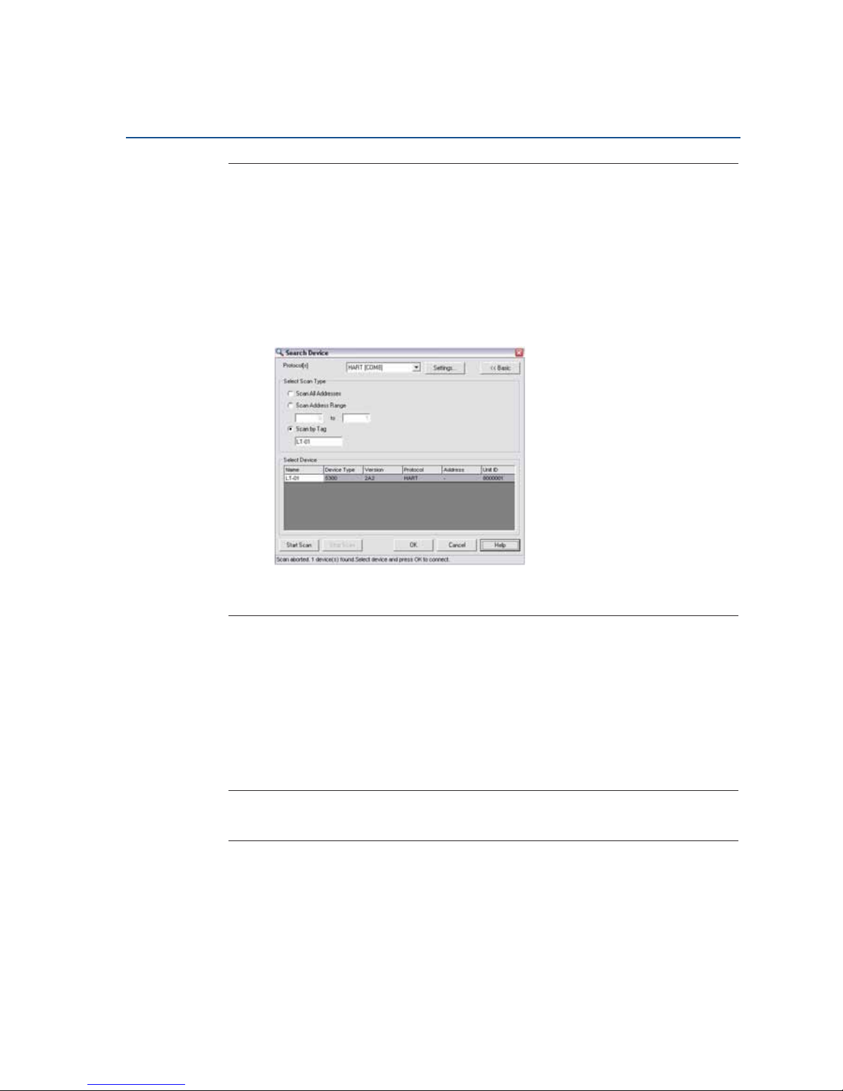
68
Reference Manual
00809-0100-4026, Rev HA
Section 4: Electrical Installation
November 2014
Electrical Installation
Note
Take the following into consideration if there are multiple Rosemount 5400 Modbus units on the
bus:
By default, the transmitters have HART address 1. It will not be possible to establish
communication on HART address 1 if several transmitters have the same address. In this case,
there are alternative solutions to establish communication:
1. Select the Scan by Tag option in the Search Device window in RRM and enter the HART
Device Tag of the transmitter. Communication can now be established with an
individual transmitter even if several devices have the same HART address.
2. Make sure the Rosemount 5400 transmitter is alone on bus. Disconnect or turn off
power from any other dcevies.
4.11.2 Connect to the HART terminals
To configure the Rosemount 5400 transmitter, connect the communicator or PC to the HART
terminals using a HART modem, see Figure 4-16 on page 62. Both the configuration tool and
the RS-485 bus can be connected simultaneously. Configuration data is sent with HART
commands through the HMC to the Rosemount 5400 transmitter electronics.
Note that the power supply must be connected during configuration, see also “Connecting the
transmitter” on page 47.
Note
Measurement data is not updated to the Modbus Master when a configuration tool is
connected.
Page 81

69
Reference Manual
00809-0100-4026, Rev HA
Section 4: Electrical Installation
November 2014
Electrical Installation
4.12 Optional devices
4.12.1 Tri-Loop™ HART to analog converter
The Rosemount 5400 Series transmitter outputs a HART signal with four process variables. The
Model 333 HART Tri-Loop provides up to three additional analog 4-20 mA outputs.
Figure 4-22. Wiring Diagram for HART Tri-Loop
Configure Channels 1, 2, and 3 to reflect the units in addition to Upper Range Values and Lower
Range Values for secondary, tertiary, and fourth variables (variable assignment is configured in
the Rosemount 5400 Series). It is also possible to enable or disable a channel from this menu.
Ch. 3
Ch. 2
Ch. 1
Each Tri-Loop
channel receives
power from
control room
Channel 1 must
be powered for
the Tri-Loop to
operate
Device receives
power from
control room
R
L
!250
:
HART Burst command 3/
analog output
IS barrier
DIN rail mounted
HART Tri-Loop
Control room
Burst input
to Tri-Loop
Page 82

70
Reference Manual
00809-0100-4026, Rev HA
Section 4: Electrical Installation
November 2014
Electrical Installation
4.12.2 751 Field Signal Indicator
Figure 4-23. Wiring Diagram for a Rosemount 5400 Series Transmitter with a 751 Field
Signal Indicator
Power supply
Rosemount 5400 Series radar transmitter
751 Field Signal
Indicator
Page 83

71
Reference Manual
00809-0100-4026, Rev HA
Section 4: Electrical Installation
November 2014
Electrical Installation
4.12.3 Smart Wireless THUM™ Adapter
The Rosemount 5400 Series can be combined with the Smart Wireless THUM Adapter.
For more information, see the Smart Wireless THUM
™
Adapter for Rosemount Process Level
Transmitter Applications Technical Note (Document No. 00840-0100-4026) and the Smart
Wireless THUM™ Adapter Reference Manual (Document No. 00809-0100-4075).
Figure 4-24. Wiring Diagram for a Rosemount 5400 Series with the Smart Wireless THUM
Adapter
Rosemount 5400 Series radar
transmitter with THUM Adapter
Rosemount Field
Communicator
RRM/Rosemount
Configuration Tool
4-20 mA/HART
Smart wireless
gateway
AMS® configurator
DCS/host system
Page 84

72
Reference Manual
00809-0100-4026, Rev HA
Section 4: Electrical Installation
November 2014
Electrical Installation
Page 85

73
Reference Manual
00809-0100-4026, Rev HA
Section 5: Basic Configuration/Start-up
November 2014
Basic Configuration/Start-up
Section 5 Basic Configuration/Start-up
Safety messages . . . . . . . . . . . . . . . . . . . . . . . . . . . . . . . . . . . . . . . . . . . . . . . . . . . . . . . . . . . . page 73
Overview . . . . . . . . . . . . . . . . . . . . . . . . . . . . . . . . . . . . . . . . . . . . . . . . . . . . . . . . . . . . . . . . . . page 74
Basic configuration parameters . . . . . . . . . . . . . . . . . . . . . . . . . . . . . . . . . . . . . . . . . . . . . . . page 75
Basic configuration using RRM . . . . . . . . . . . . . . . . . . . . . . . . . . . . . . . . . . . . . . . . . . . . . . . . page 84
Configuration using a Field Communicator . . . . . . . . . . . . . . . . . . . . . . . . . . . . . . . . . . . . . page 101
Basic configuration using AMS Suite . . . . . . . . . . . . . . . . . . . . . . . . . . . . . . . . . . . . . . . . . . . page 105
Configuration using DeltaV . . . . . . . . . . . . . . . . . . . . . . . . . . . . . . . . . . . . . . . . . . . . . . . . . . page 106
F
OUNDATION fieldbus overview . . . . . . . . . . . . . . . . . . . . . . . . . . . . . . . . . . . . . . . . . . . . . . . . page 112
Application examples . . . . . . . . . . . . . . . . . . . . . . . . . . . . . . . . . . . . . . . . . . . . . . . . . . . . . . . page 115
Tri-Loop™ HART to Analog Converter . . . . . . . . . . . . . . . . . . . . . . . . . . . . . . . . . . . . . . . . . . page 117
HART multidrop configuration . . . . . . . . . . . . . . . . . . . . . . . . . . . . . . . . . . . . . . . . . . . . . . . . page 118
5.1 Safety messages
Procedures and instructions in this section may require special precautions to ensure the safety
of the personnel performing the operations. Information that raises potential safety issues is
indicated by a warning symbol ( ). Refer to the safety messages listed at the beginning of each
section before performing an operation preceded by this symbol.
Explosions could result in death or serious injury.
Verify that the operating environment of the gauge is consistent with the appropriate
hazardous locations certifications.
Before connecting a HART
®
-based communicator in an explosive atmosphere, make sure
the instruments in the loop are installed in accordance with intrinsically safe or
non-incendive field wiring practices.
Do not remove the gauge cover in explosive atmospheres when the circuit
is alive.
All connection head covers must be fully engaged to meet explosion-proof
requirements.
Failure to follow safe installation and servicing guidelines could result in death or
serious injury.
Make sure only qualified personnel perform the installation.
Use the equipment only as specified in this manual. Failure to do so may impair the
protection provided by the equipment.
Do not perform any service other than those contained in this manual unless you are
qualified.
Page 86

74
Reference Manual
00809-0100-4026, Rev HA
Section 5: Basic Configuration/Start-up
November 2014
Basic Configuration/Start-up
5.2 Overview
The configuration of a Rosemount 5400 Series transmitter is normally a simple and straightforward task. If the transmitter is pre-configured at the factory according to ordering specifications
in the Configuration Data Sheet, no further basic configuration is required, unless tank
conditions have changed.
The Rosemount 5400 Series supports a set of advanced configuration options that can be used
to handle special tank conditions and applications. For further information on advanced
configuration options, see Appendix C: Advanced Configuration.
5.2.1 Basic configuration parameters
The basic configuration includes parameters for a standard configuration which is sufficient in
most cases. The basic configuration comprises the following items:
Measurement Units
Tank Configuration
- Tank Geometry
- Environment
- Volume
Analog Output
Echo Tuning: see page 83 for more information on the Amplitude Threshold Curve
(ATC), and “Echo tuning” on page 83 for more information on False Echo Registration
5.2.2 Configuration tools
There are several tools available for basic configuration of a Rosemount 5400 Series transmitter:
RRM. Note that RRM is required for advanced configuration features.
See “Basic configuration using RRM” on page 84 for information on using RRM to
configure the Rosemount 5400 Series.
Rosemount Field Communicator.
See “Configuration using a Field Communicator” on page 101 for the Field
Communicator Menu Tree.
DTM (compliant with version 1.2 of the FDT
®
/DTM™ specification) is also available
supporting configuration in, for instance, Yokogawa Fieldmate/PRM, E+H
TM
FieldCare,
and PACTware
TM
AMS® Suite software (for HART).
See “Basic configuration using AMS Suite” on page 105 for information on configuring
AMS Suite.
DeltaV
TM
(only for FOUNDATION™ fieldbus).
See “Configuration using DeltaV” on page 106 for information on configuring the
Rosemount 5400 Series transmitter using DeltaV.
Other tools that support EDDL functionality.
RRM is a user-friendly, Windows
™
based software package that includes waveform plots,
offline/online configuration Wizard, logging, and extensive online help.
Page 87

75
Reference Manual
00809-0100-4026, Rev HA
Section 5: Basic Configuration/Start-up
November 2014
Basic Configuration/Start-up
To communicate with the transmitter using RRM, a HART modem (part number
03300-7004-0001 or 03300-7004-0002) or a F
OUNDATION fieldbus modem (part number
03095-5108-0001 for PCMCIA) is required. For F
OUNDATION fieldbus communication you will
also need the National Instruments Communication Manager software (see “Installing the RRM
software for F
OUNDATION fieldbus” on page 88).
5.3 Basic configuration parameters
This chapter describes the basic parameters that need to be configured for a Rosemount 5400
transmitter. If the transmitter is factory-configured according to the ordering specifications in
the Configuration Data Sheet, no further basic configuration is needed unless conditions have
changed since the ordering date.
Different configuration tools are described at the end of this section.
5.3.1 Measurement units
Measurement units can be specified for presentation of Level, Level Rate, Volume and
Tem per atu re va lues.
5.3.2 Tank geometry
Tank height
The Tank Height is the distance between the Upper Reference Point, at the underside of the
transmitter flange or the threaded adapter, and the Lower Reference Point, close to or at the
bottom of the tank (see Figure 5-2 for further information on Upper Reference Points for
various tank connections). The transmitter measures the distance to the product surface and
subtracts this value from the Tank Height to determine the product level.
Figure 5-1. Tank Geometry
Tan k h eig ht (R )
Product level
Upper reference point
Lower reference point
(Level = 0)
Tra nsi tion zon e
Page 88

76
Reference Manual
00809-0100-4026, Rev HA
Section 5: Basic Configuration/Start-up
November 2014
Basic Configuration/Start-up
Figure 5-2. Upper Reference Point
Tank type and tank bottom type
The Rosemount 5400 Series transmitter is optimized according to the Tank Type and Tan k
Bottom Type configuration by automatically setting some parameters to predefined default
values.
Select Tank Bottom Type Flat Inclined if the bottom inclination is between 10 and 30 degrees. If
the inclination is less than 10 degrees, but there are disturbing objects on the tank floor (like
heating coils) within the radar beam, this selection should also be used. If the inclination is
greater than 30 degrees, use the Cone Ta nk B ottom Ty pe.
Table 5-1. Tank Type and Tank Bottom Type
Figure 5-3. Transmitter Optimization for Different Tank Types and Bottom Shapes
Tan k type Tank bottom type
Vertical cylinder Flat, dome, cone, flat inclined/obstructed
Horizontal cylinder Not used
Spherical Not used
Cubical Flat, dome, cone, flat inclined/obstructed
Cone antenna
Rod antenna
with flange
Rod antenna with
threaded tank
connection
Upper reference point
Adapter
Flange
Process seal
antenna
Flat Dome ConeFlat inclined Spherical
Page 89

77
Reference Manual
00809-0100-4026, Rev HA
Section 5: Basic Configuration/Start-up
November 2014
Basic Configuration/Start-up
Pipe diameter
When the transmitter is mounted in a still-pipe, the inner diameter of the pipe must be
specified. The pipe diameter is used to compensate for the lower microwave propagation speed
inside the pipe. An incorrect value gives a scale factor error. If locally supplied still-pipes are
used, make sure the inner diameter is noted before the pipe is installed.
Transition zone
The measurement accuracy is reduced within the transition zone region 6 in. (150 mm) from
the lower end of the antenna. It is recommended that the Upper Range Value (20 mA) be set
outside the transition zone.
5.3.3 Process conditions
Describe the conditions of the tank according to the tank environment parameters for process
conditions listed below. For best performance, choose only if applicable, and no more than
two options.
Rapid level changes
Optimize the transmitter for measurement conditions where the level changes quickly from the
filling and emptying of the tank. As a default standard, a Rosemount 5400 Series transmitter is
able to track level changes of up to 1.5 in./s (40 mm/s). When the Rapid Level Changes
check-box is selected, the transmitter can track level changes of up to 8 in./s (200 mm/s).
Turbulent sur face
This parameter should be used if the tank has a turbulent surface. The reason for the turbulence
might be splash loading, agitators, mixers, or boiling product. Normally, the waves in a tank are
quite small and cause local rapid level changes. By setting this parameter, the performance of
the transmitter will improve when there are small and quickly changing amplitudes and levels.
Foam
Setting this parameter optimizes the gauge for conditions with weak and varying surface echo
amplitudes, such as foam. When the foam is light and airy, the actual product level is measured.
For heavy and dense foam, the transmitter measures the level of the foam’s upper surface.
Product dielectric range
The Dielectric Constant is related to the reflectivity of the product. By setting this parameter,
measurement performance can be optimized. However, the transmitter will still be able to
perform properly, even if the actual Dielectric Constant differs from the configured value.
Solid product
Setting this parameter optimizes the device for solid products, for example concrete or grains.
For instance, this parameter can be used when the application is a silo with product pile-up. The
transmitter will be optimized for weak echoes and a sloping surface which is typical when
measuring at solid materials. This option shall only be used for a Rosemount 5402 with a 4” cone
antenna.
Page 90

78
Reference Manual
00809-0100-4026, Rev HA
Section 5: Basic Configuration/Start-up
November 2014
Basic Configuration/Start-up
5.3.4 Volume configuration
For volume calculations, choose one of the standard tank shapes or the strapping option. Select
None if volume calculation is not used. For the standard tanks, a Volume Offset parameter can
be specified which can be used for a non-zero volume that corresponds to the zero level. This
may be useful, for example, if the user wants to include the product volume below the zero level.
Volume calculation is performed by using a predefined tank shape or a strapping table. One of
the following standard tank shapes can be chosen:
Sphere
Vertical cylinder
Horizontal cylinder
Vertical bullet
Horizontal bullet
The following parameters must be entered for a standard tank shape:
Tank diameter
Tank height (not for spherical tanks)
Volume offset
Page 91

79
Reference Manual
00809-0100-4026, Rev HA
Section 5: Basic Configuration/Start-up
November 2014
Basic Configuration/Start-up
Standard tank shapes
Figure 5-4. Standard Tank Shapes
Vertical cylinder
Vertical cylinder tanks are specified by
diameter, height, and volume offset.
Horizontal cylinder
Horizontal cylinder tanks are specified by
diameter, height, and volume offset.
Vertical bullet
Vertical bullet tanks are specified by
diameter, height, and volume offset. The
volume calculation model for this tank
shape estimates that the radius of the
bullet end is equal to the diameter/2.
Horizontal bullet
Horizontal bullet tanks are specified by
diameter, height, and volume offset. The
volume calculation model for this tank
shape estimates that the radius of the
bullet end is equal to the diameter/2.
Sphere
Spherical tanks are specified by diameter
and volume offset.
Diameter Height
Diameter
Height
Diameter Height
Diameter
Height
Diameter
Page 92

80
Reference Manual
00809-0100-4026, Rev HA
Section 5: Basic Configuration/Start-up
November 2014
Basic Configuration/Start-up
Strapping table
The Strapping Table option is used when the tank shape deviates significantly from an ideal
sphere or cylinder, or when high volume accuracy is required.
The Strapping Table divides the tank into segments. Level values and corresponding volumes
are entered at the bottom of the tank. These figures can typically be obtained from tank
drawings or from a certificate provided by the tank manufacturer. A maximum of 20 strapping
points can be entered. For each level value the corresponding total volume up to the specified
level is entered.
The volume value is interpolated if the product surface is between two level values in the table.
Figure 5-5. Strapping Points
Actual tank bottom may look like this.
Using only 3 strapping points results in a level-to-volume profile
that is more angular than the actual shape.
Using 10-15 of the points at the bottom of the tank yields a
level-to-volume profile that is similar to the actual tank bottom.
Page 93

81
Reference Manual
00809-0100-4026, Rev HA
Section 5: Basic Configuration/Start-up
November 2014
Basic Configuration/Start-up
5.3.5 Analog output (HART)
For the analog output, the output source (primary value), range values, and alarm mode are
specified.
Figure 5-6. Standard Range Value Settings
Output source/primary variable
Specify the source to control the analog output. Typically, the Primary Value is configured to be
the Product Level.
Upper/lower range value
Enter the range values that correspond to the analog output values 4 and 20 mA. The 20 mA
point should be set below the Transition Zone, since the measurement accuracy is reduced in
this region. For information on the Transition Zone, see “Performance specifications” on
page 189.
If a measured value goes beyond the measurement range, the transmitter enters saturation
mode (if limit alarm is disabled) or alarm mode, depending on the current configuration.
Alarm mode
Choose the desired Alarm mode to specify the analog output state when there is a failure or a
measurement error.
High: the output current is set to the High Alarm Limit.
Low: the output current is set to the Low Alarm Limit.
20 mA Upper Range Value (URV)
Product level
4 mA Lower Range Value (LRV)
Range 0-100 %
Lower reference point
(Level=0)
Upper reference point
Tra nsi ti on z one
Page 94

82
Reference Manual
00809-0100-4026, Rev HA
Section 5: Basic Configuration/Start-up
November 2014
Basic Configuration/Start-up
Freeze Current: the output current is set to the last valid value at the time when the error
occurs.
Default settings for alarm mode:
Measurement errors: Output current = High
Measured value out of range: transmitter enters saturation mode (if Limit Alarm is
disabled)
Table 5-2. Analog Output: Standard Alarm Value vs. Saturation Value
In saturation mode, if the primary variable is not in low alarm mode, the minimum output is 3.9
mA. If the primary variable is not in high alarm mode, the maximum output is 20.8 mA.
Table 5-3. Analog Output: NAMUR-compliant Alarm Value vs. Saturation Value
5.3.6 Level and distance calibration
Level and distance calibration may be necessary when using a nozzle or pipe or if there are
disturbances in the near zone caused by a physical object.
Non-metallic (e.g. plastic) vessels and installation geometry may introduce an offset for the zero
reference point. This offset may be up to ± 25 mm. The offset can be compensated for using
Distance Calibration.
When calibrating the transmitter, it is important that the product surface is calm and that the
tank is not being filled or emptied.
A complete calibration is performed in two steps:
1. Calibrate the distance measurement by adjusting the Calibration Offset parameter.
2. Calibrate the level measurement by adjusting the Tank Height.
Level 4–20 mA saturation value 4–20 mA alarm value
Low 3.9 mA 3.75 mA
High 20.8 mA 21.75 mA
Level 4–20 mA saturation value 4–20 mA alarm value
High 20.5 mA 22.5 mA
Page 95

83
Reference Manual
00809-0100-4026, Rev HA
Section 5: Basic Configuration/Start-up
November 2014
Basic Configuration/Start-up
Distance calibration
1. Measure the actual distance between the Upper Reference Point and the product
surface.
2. Adjust the Calibration Distance so that the Distance measured by the transmitter
corresponds to the actual distance.
The Calibration Distance parameter is available via
HART command [2, 3, 2, 4, 1],
or
RRM:
a. Select the Ta n k icon under Device Config/Setup in the RRM workspace.
b. In the Tan k window, select the Geometry tab.
c. Select the Advanced button.
d. Enter the desired value in the Calibration Distance field and select the Store button.
Level calibration
1. Measure the actual Product Level.
2. Adjust the Tank H eigh t so the product level measured by the transmitter corresponds
to the actual product level.
Figure 5-7. Distance and Level Calibration
5.3.7 Echo tuning
When Basic Configuration is performed, the transmitter may need to be tuned to handle
disturbing objects in the tank. There are different methods available for handling disturbance
echoes with the Rosemount 5400 Series Transmitter:
ATC
False echo registration, see “Registration of false echoes” on page 135
The Guided Setup in the RRM configuration program includes a Measure and Learn function which
automatically registers false echoes and creates an ATC (see “Guided setup” on page 92).
The created ATC is based on the present tank spectra and process condition settings.
Disturbances below the product surface might not be handled by the Measure and Learn
function.
Refere nce point
Distance
Reference point
Tank height
Level
Page 96

84
Reference Manual
00809-0100-4026, Rev HA
Section 5: Basic Configuration/Start-up
November 2014
Basic Configuration/Start-up
5.3.8 ATC
Setting up an ATC makes tracking of the product surface more robust in the presence of noise
and weak disturbing echoes. The ATC is normally used for filtering out disturbances with an
amplitude smaller than the amplitude of the product surface echo.
The ATC is designed as a number of individually adjustable amplitude threshold points.
Figure 5-8. Weak Disturbing Echoes can be Filtered Out by Creating an Amplitude
Threshold
To create an ATC, the Measure and Learn function is available in the RRM program.
5.4 Basic configuration using RRM
The RRM is a user-friendly software tool that allows configuration of the Rosemount 5400
transmitter. Choose either of the following methods to configure a Rosemount 5400
transmitter with RRM:
Guided Setup, if you are unfamiliar with the Rosemount 5400 Series transmitter (see
page 92)
Setup functions, if you are already familiar with the configuration process, or for
changes to the current settings (see page 100)
5.4.1 System requirements
Hardware
COM Port: 1 serial COM por t or 1 USB port
Graphical Card (minimum/recommended): screen resolution 800 x 600/1024 x 768.
Hard drive space: 100 MB
ATC
Measurement signal
Amplitude, mV
Distance, m
Page 97

85
Reference Manual
00809-0100-4026, Rev HA
Section 5: Basic Configuration/Start-up
November 2014
Basic Configuration/Start-up
Software
Operating Systems supported:
Windows XP
Windows 7
5.4.2 Help in RRM
From the Help menu, select the Contents option to access help information. Help is also
available from a Help button in most windows.
5.4.3 Installing the RRM software for HART communication
To install the RRM:
1. Insert the installation CD into the CD-ROM drive.
2. If the installation program is not started automatically, select Run from the Windows
Start bar.
3. Enter D:\RRM\Setup.exe where D is the CD-ROM drive.
4. Follow the instructions on the screen.
5. Make sure that HART is chosen as default protocol.
6. Set COM Port Buffers to 1, see page 88.
Page 98

86
Reference Manual
00809-0100-4026, Rev HA
Section 5: Basic Configuration/Start-up
November 2014
Basic Configuration/Start-up
Getting started
1. From the Start menu, select Programs > Rosemount > Rosemount Radar Master or
select the RRM icon in the Windows workspace.
2. If the Search Device window did not appear automatically, select menu option Device >
Search.
3. In the Search Device window, select communication protocol HART and select the Start
Scan button (select the Advanced button to specify start and stop address).
Now RRM searches for the transmitter.
4. The Search Device window presents a list of found transmitters.
5. Select the desired transmitter and press OK to connect. If communication does not
work, check that the correct COM port is configured correctly and is connected to the
computer. See “Specifying the COM port” on page 87. Verify from the Communication
Preferences window that HART communication is enabled.
6. The RRM Status Bar can be used to verify that RRM is communicating with the
transmitter:
RRM communicates
with the transmitter
No communication
with the transmitter
Page 99

87
Reference Manual
00809-0100-4026, Rev HA
Section 5: Basic Configuration/Start-up
November 2014
Basic Configuration/Start-up
5.4.4 Specifying the COM port
If communication is not established, open the Communication Preferences window and check
that the correct COM Port is selected:
1. From the View menu, select Communication Preferences in RRM.
Figure 5-9. Communication Settings
2. Make sure that HART communication is enabled.
3. Check which COM port is connected to the modem.
4. Select the COM port option matching the actual COM port on the PC that is connected
to the transmitter.
Page 100

88
Reference Manual
00809-0100-4026, Rev HA
Section 5: Basic Configuration/Start-up
November 2014
Basic Configuration/Start-up
5.4.5 To set the COM port buffers
The COM port Receive Buffer and Transmit Buffer need to be set to 1 by doing the following:
1. In the Microsoft
®
Windows Control Panel, open the System option.
2. Select the Hardware tab and click the Device Manager button.
3. Expand the Ports node in the tree view.
4. Click the right mouse button on the selected COM port and then select Properties.
5. Select the Port Settings tab and click the Advanced button.
6. Drag the Receive Buffer and Tran smit Buf fer slides to 1.
7. Click the OK button.
8. Reboot the computer.
5.4.6 Specifying measurement units
Measurement units for data presentation in RRM can be specified when the RRM program is
installed. Units can also be changed as follows:
1. Select the Application Preferences option from the View menu.
2. Select the Measurement Units tab.
3. Select the desired units for Length, Level Rate, Volume, and Te m pe ra tu re .
5.4.7 Installing the RRM software for FOUNDATION fieldbus
To install the RRM for FOUNDATION fieldbus communication:
1. Start by installing the National Instruments Communication Manager software. See
National Instruments manual (Getting started with your PCMCIA-FBUS and the NI-FBUS™
software) for more information.
2. Insert the RRM installation CD into your CD-ROM drive.
3. If the installation program is not automatically started, select Run from the Windows
Start bar.
4. Type D:\RRM\Setup.exe where D is the CD-ROM drive.
5. Follow the instructions on the screen.
6. Make sure that F
OUNDATION fieldbus is selected as default protocol.
 Loading...