

Emerson Rosemount 5300 Series, Rosemount 5302, Rosemount 5301, Rosemount 5303 Product Data Sheet
Product Data Sheet
00813-0100-4530, Rev DA
December 2010
Rosemount 5300 Series
Superior Performance Guided Wave Radar
Level and Interface Transmitter
• Industry leading measurement capability and
reliability provided by direct switch technology
• Increased plant availability with advanced
diagnostics and PlantWeb
• Increased safety and proven FMEDA suitable
for SIL2 with a SFF>90%
• Reduced cost and increased safety from the
robust modular design
• Reduced instrument count and process
penetrations with a MultiVariable™ transmitter
• Improved throughput and product quality due
to superior performance and accuracy
• Reduced startup cost through powerful and
easy-to-use configuration tools and seamless
plant integration
• Improved EMC performance and higher
safety with smart galvanic interface
• Reduced operating costs with predictive
maintenance and easy troubleshooting
®
functionality
Contents
Taking Guided Wave Radar Benefits to the Next Level . . . . . . . . . . . . . . . . . . . . . . page 2
Ordering Information . . . . . . . . . . . . . . . . . . . . . . . . . . . . . . . . . . . . . . . . . . . . . . . . page 4
Specifications. . . . . . . . . . . . . . . . . . . . . . . . . . . . . . . . . . . . . . . . . . . . . . . . . . . . . page 16
Functional Specification . . . . . . . . . . . . . . . . . . . . . . . . . . . . . . . . . . . . . . . page 16
Performance Specification . . . . . . . . . . . . . . . . . . . . . . . . . . . . . . . . . . . . . page 28
Physical Specification. . . . . . . . . . . . . . . . . . . . . . . . . . . . . . . . . . . . . . . . . page 31
Product Certifications. . . . . . . . . . . . . . . . . . . . . . . . . . . . . . . . . . . . . . . . . . . . . . . page 36
Dimensional Drawings . . . . . . . . . . . . . . . . . . . . . . . . . . . . . . . . . . . . . . . . . . . . . . page 39
www.rosemount.com
A.P.O. - ELMOS v.o.s., Pražská 90, 509 01 Nová Paka, Tel.: +420 493 504 261, Fax: +420 493 504 257, E-mail: apo@apoelmos.cz, Internet: www.apoelmos.cz
Product Data Sheet
Signal curve after Dynamic
Vapor Compensation
Signal curve before Dynamic
Vapor Compensation
Reference
pulse
Level
Interface level
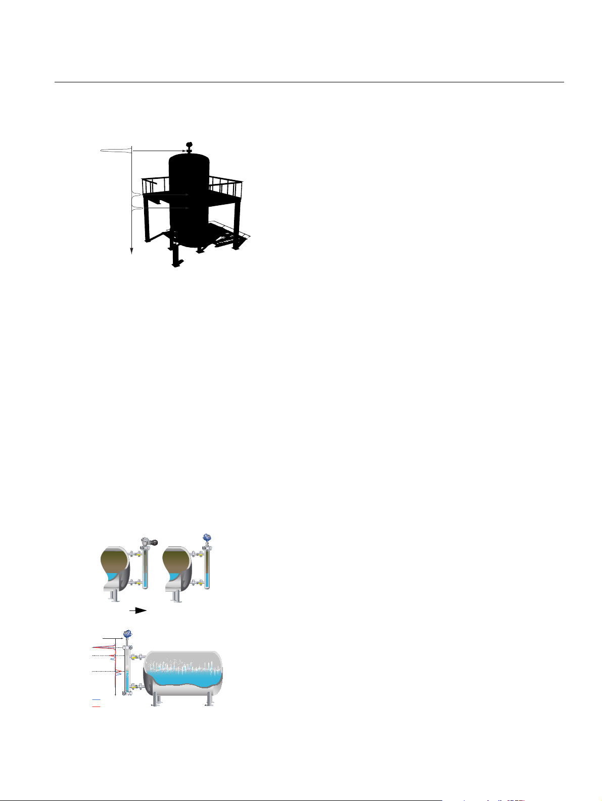
High application flexibility
Accuracy in saturated steam
From this... to this... in minutes
Displacer
Guided wave radar
00813-0100-4530, Rev DA
Rosemount 5300 Series
December 2010
Taking Guided Wave Radar Benefits to the Next Level
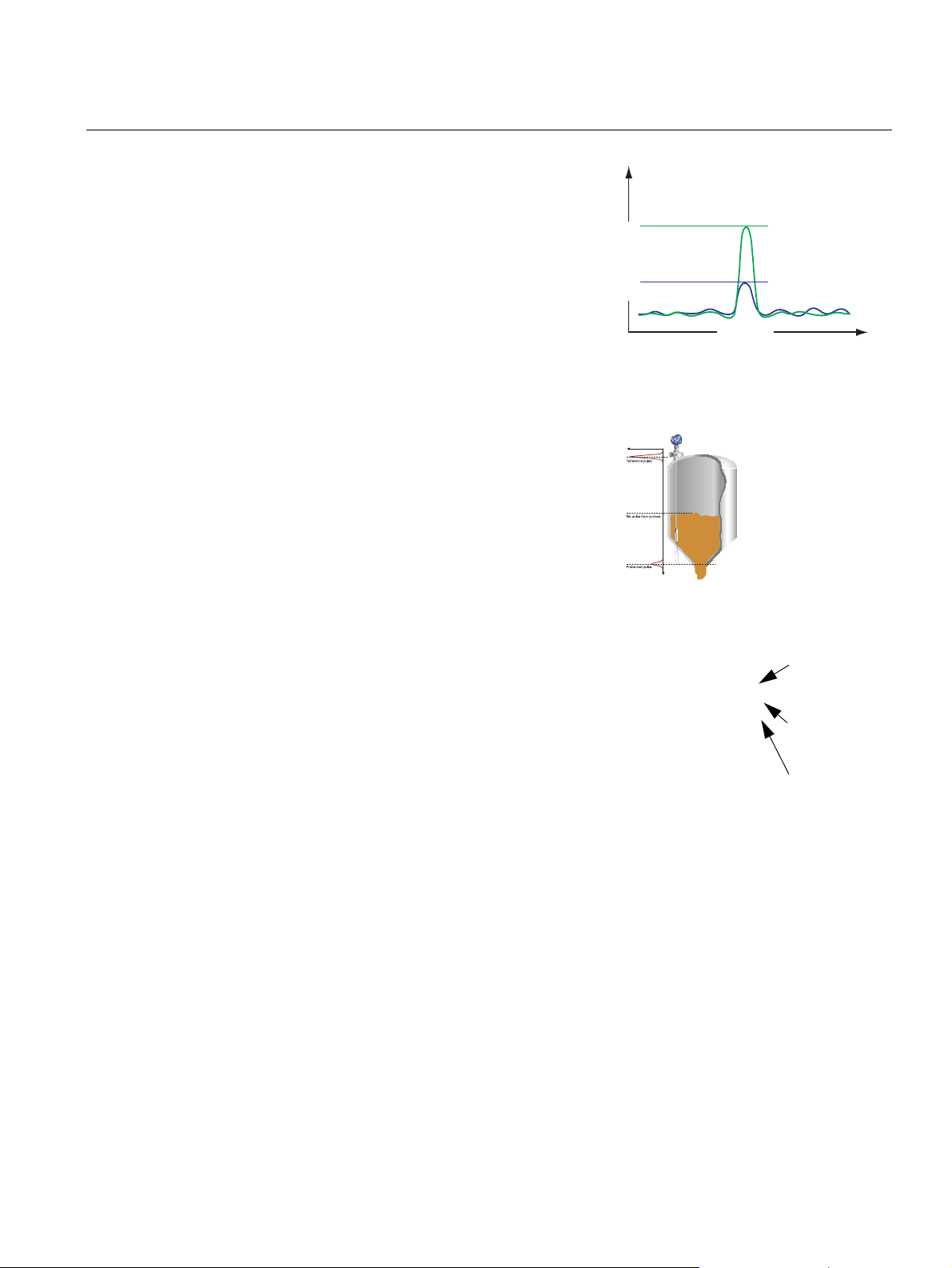
MEASUREMENT PRINCIPLE
Low power, nano-second microwave pulses are guided down a
probe submerged in the process media. When a microwave pulse
reaches a media with a different dielectric constant, part of the
energy is reflected back to the transmitter.
The transmitter uses the residual wave of the first reflection for
measuring the interface level. Part of the wave, which was not
reflected at the upper product surface, continues until it is reflected at
the lower product surface. The speed of this wave depends fully on
the dielectric constant of the upper product.
The time difference between the transmitted and the refle cte d pu lse
is converted into a distance, and the total level or interface level is
then calculated. The reflection intensity depends on the dielectric
constant of the product. The higher the dielectric constant value, the
stronger the reflection is.
GUIDED WAVE RADAR TECHNOLOGY BENEFITS
• Highly accurate and reliable direct level measurement with no
compensation needed for changing process conditions (such as
density, conductivity, viscosity, pH, temperature, and pressure)
• No moving parts and no re-calibration result in minimized
maintenance
• Handles vapor, dust, turbulence, and foam well
• Suitable for small tanks, difficult tank geometry, internal obstacles,
and unaffected by the mechanical design of chambers
• Top down installation minimizes risk for leakage s
SPECIAL 5300 FEATURES
Optimized to Suit More Applications
• Suitable for most liquid and solids level applications and liquid
interface applications
• Innovations to handle even the most challenging applications
reliably, including process vessels, control, and safety
• A wide selection of materials, process connections, probe styles,
and accessories
• A wide range of options to find the best fit in existing chambers, or a
complete assembly with Rosemount 9901 high quality chambers
• The Dynamic Vapor Compensation (DVC) option automatically
compensates for changes in the vapor space dielectric
2
Product Data Sheet
Signal strength
Distance
With Direct Switch
Technology
Without Direct Switch
Technology
DST provides a signal that is two to
five times stronger than other GWR
transmitters’
With PEP, the
surface
position is
calculated if the
surface echo
becomes
unavailable
Secondary gas
tight seal
decoupled from
the process
Flexible probe
load and
locking system
Dual ceramic
temperature
and pressure
seal
Robust modular design
Rosemount Radar Master enables
easy configuration and service with
wizard, online help, echo curve and
logging tools, and much more
00813-0100-4530, Rev DA
December 2010
Best Performance and Uptime
• Unique Direct Switch Technology (DST) and Probe End
Projection (PEP) improve measurement capability and reliability
• Ability to use single lead probe for long measuring ranges,
obstructions and low dielectrics ensures reliability in more
applications, such as viscous media
• PEP provides a backup function for challenging appl ications such
as plastic pellets and boiling hydrocarbons
• Smart Galvanic Interface results in a more stable micro wave and
EMI performance with minimized effects from outside disturbances
Robust Design Reduces Costs and Increases Safety
• Heavy-duty unique probe solution for extreme temperature and
pressures with a multiple layer of protection
• EchoLogics and smart software functions provide enhanced ability
to keep track of the surface and detect a full vessel situation
• Third party approved for overfill protection and Safety Integrated
System SIL2 suitability
• Electronics and cable connections in separate compartments
provides safer handling and improved moisture protection
Rosemount 5300 Series
Easy Installation and Plant Integration
• Easy upgrade by matching existing tank connections and
cut-to-fit probes
• MultiVariable™ device reduces the number of process
penetrations
• Seamless system integration with HART®, F
Modbus, or IEC 62591 (WirelessHART) with the Smart Wireless
THUM™ adapter
• Pre-configur ed or easy configuration in Rosemount Radar Ma ster
with a five-step wizard, auto connect, and online help
• Enhanced DD with step-by-step configuration and echo curve
capability (HART) in tools such as AMS Device Manager, and
Field Communicator
• DTM with echo curve capability for use in FDT/DTM compatible
configuration tools such as PACTWare™, Yokogawa
FieldMate/PRM
Minimized Maintenance Reduces Cost
• Easy online troubleshooting with user friendly software, utilizing
powerful echo curve and logging tools
• Signal Quality Metrics (SQM) diagnostics to detect product
build-up on probe or to monitor turbulence, boiling, foam, and
emulsions
• Predictive maintenance with advanced diagnostics and
PlantWeb alerts
• Modular design for reduced spare parts and easy replacement of
the head without opening the tank
OUNDATION
™ fieldbus,
®
3

Rosemount 5300 Series
Ordering Information
Rosemount 5301 and 5302
Level and/or Interface in Liquids
Rosemount 5301 and 5302 Guided Wave Radar Level transmitters provide industry
leading measurement capabilities and reliability in liquids. Characteristics include:
• Direct Switch Technology and Probe End Projection to han dle low reflective media
and long measuring ranges
• Wide range of probe styles, materials, and temperatures and pressures for
application flexibility
• HART 4-20 mA, F
the Smart Wireless THUM adapter
• Prior use SIL 2 suitable (QS Option)
• Advanced Diagnostics (D01 & DA1 Options)
Additional Information
Specifications: page 16
Certifications: page 36
Dimensional drawings: page 39
OUNDATION fieldbus
Product Data Sheet
00813-0100-4530, Rev DA
December 2010
, Modbus, or IEC 62591 (WirelessHART) with
TABLE 1. 5301 and 5302 Level and/or Interface in Liquids Ordering Information
★ The Standard offering represents the most common options. The starred options (★) should be selected for best delivery.
The Expanded offering is subject to additional delivery lead time.
Model Product Description
5301 Guided Wave Radar Liquid Level or Interface Transmitter (interface available for fully submerged probe)
5302 Guided Wave Radar Liquid Level and Interface Transmitter
Signal Output
Standard Standard
H 4-20 mA with HART communication ★
FF
M RS-485 with Modbus communication ★
Housing Material
Standard Standard
A Polyurethane-covered Aluminum ★
Expanded
S Stainless Steel, Grade CF8M (ASTM A743)
Conduit / Cable Threads
Standard Standard
1 ½ - 14 NPT ★
2 M20 x 1.5 adapter ★
E M12, 4-pin, Male connector (eurofast
M A size Mini, 4-pin, Male connector (minifast
Operating Temperature and Pressure
Standard Standard
S - 15 psig (-1bar) to 580 psig (40 bar) @ 302 °F (150 °C) All ★
H High Temperature / High Pressure
OUNDATION fieldbus ★
®)(1)
®)(1)
(2)
(3)
2940 psi @ 752 °F and 5000 psi @ 100 °F (203 bar @ 400 °C and 345 bar @ 38 °C)
:
Probe Type
3A, 3B, 4A, 4U, 4V, 5A and
5B
★
★
★
4

Product Data Sheet
00813-0100-4530, Rev DA
December 2010
TABLE 1. 5301 and 5302 Level and/or Interface in Liquids Ordering Information
★ The Standard offering represents the most common options. The starred options (★) should be selected for best delivery.
The Expanded offering is subject to additional delivery lead time.
P High Pressure
Max 392 °F (200 °C): 3500 psi @ 392 °F and 5000 psi @ 100 °F (243 bar @ 200 °C
and 345 bar @ 38 °C)
Expanded
C
Cryogenic Temperature
Max 392 °F (200 °C): 3500 psi @ 392 °F and 5000 psi @ 100 °F (243 bar
@ 200 °C and 345 bar @ 38 °C)
Material of Construction
Probe
Standard Standard
1 316L SST (EN 1.4404) All S, H, P, C ★
Expanded
2 Alloy C-276 (UNS N10276). With plate
design if flanged version. Up to class 600,
PN 63 for HTHP/HP probes.
3 Alloy 400 (UNS N04400). With plate
design if flanged version.
7 PTFE covered probe and flange. With
plate design.
8 PTFE covered probe 4A and 5A S
H Alloy C-276 (UNS N10276) process
connection, flange, and probe
Sealing, O-ring Material (Consult the factory for other o-ring materials)
Standard Standard
N None
VViton
(7)
®
E Ethylene Propylene ★
KKalrez
B Buna-N ★
Probe Type Process Connection Probe Lengths
Standard Standard
3B Coaxial, perforated. For level and interface
measurement, or easier cleaning.
4A Rigid Single Lead (8 mm) Flange / 1 in.
4B Rigid Single Lead (13 mm)
5A Flexible Single Lead with weight
5B Flexible Single Lead with chuck
Expanded
1A Rigid Twin Lead
2A Flexible Twin Lead with weight
3A Coaxial (for level measurement)
4U Dynamic Vapor Compensation
Single Rigid Probe for 2 in. pipes
(3)
:
(3) (4)
-321 °F (-196 °C)
(5)
: Process Connection /
Probe Type Valid Operation
3A, 3B, 4A S, H, P
3A, 3B, 4A, 5A, 5B S
4A and 5A S
(6)
3A, 3B, 4A H, P
fluoroelastomer ★
®
6375 perfluoroelastomer ★
Flange / 1 in.
(12)
, 1.5 in., 2 in.
(12)
, 1.5 in., 2 in.
/ Tri-Clamp
(8)
Flange / 1 in., 1.5 in., 2 in. Thread /
Tri-Clamp
(9)
Flange / 1 in.
(12)
, 1.5 in., 2 in.
/ Tri-Clamp
(10)
Flange / 1 in.
(12)
, 1.5 in., 2 in.
/ Tri-Clamp
(12)
Flange / 1.5 in., 2 in.
(12)
(11)
Flange / 1 in.
(13)
Flange / 1.5 in., 2 in.
Flange / 1.5 in. Thread
(12)
(12)
(12)
, 1.5 in., 2 in.
Thread Min: 1 ft 4 in. (0.4 m). Max: 9
Thread Min: 3 ft 4 in. (1 m). Max: 164
Rosemount 5300 Series
3B, 4A, 5A, and 5B ★
3A, 3B, 4A, 5A, 5B (Only
SST)
Temperature and Pressure
(12)
Thread Min: 1 ft 4 in. (0.4 m). Max:
(12)
Thread
(12)
Thread
(12)
Thread
(12)
Thread Min: 1 ft 4 in. (0.4 m). Max:
19 ft 8 in. (6 m)
Min: 1 ft 4 in. (0.4 m). Max: 9
ft 10 in. (3 m)
Min: 1 ft 4 in. (0.4 m). Max:
14 ft 9 in.
(4.5 m)
Min: 3 ft 4 in. (1 m). Max: 164
ft (50 m)
Min: 3 ft 4 in. (1 m). Max: 164
ft (50 m)
ft 10 in. (3 m)
ft (50 m)
19 ft 8 in. (6 m)
Min: 2 ft 5 in. (0.76 m). Max:
13 ft (4 m)
★
★
★
★
★
★
5

Product Data Sheet
00813-0100-4530, Rev DA
Rosemount 5300 Series
TABLE 1. 5301 and 5302 Level and/or Interface in Liquids Ordering Information
★ The Standard offering represents the most common options. The starred options (★) should be selected for best delivery.
The Expanded offering is subject to additional delivery lead time.
4V Dynamic Vapor Compensation
Probe Length Units
Standard Standard
E English (feet, in.) ★
M Metric (meters, centimeters) ★
Total Probe Length
Standard Standard
xxx 0-164 ft or 0-50 m ★
Total Probe Length
Standard Standard
xx 0-11 in. or 0-99 cm ★
Process Connection - Size / Type (consult the factory for other process connections)
ASME / ANSI Flanges
Standard Standard
AA 2 in., 150 lb ★
AB 2 in., 300 lb ★
AC 2 in., 600 lb. HTHP / HP units ★
AD 2 in., 900 lb. HTHP / HP units ★
BA 3 in., 150 lb ★
BB 3 in., 300 lb ★
BC 3 in., 600 lb. HTHP / HP units ★
BD 3 in., 900 lb. HTHP / HP units ★
CA 4 in., 150 lb ★
CB 4 in., 300 lb ★
CC 4 in., 600 lb. HTHP / HP units ★
CD 4 in., 900 lb. HTHP / HP units ★
Expanded
AE 2 in., 1500 lb. HTHP / HP units
AI 2 in., 600 lb, RTJ (Ring Type Joint). HTHP / HP units
AJ 2 in., 900 lb, RTJ (Ring Type Joint). HTHP / HP units
AK 2 in., 1500 lb, RTJ (Ring Type Joint). HTHP / HP units
BE 3 in., 1500 lb. HTHP / HP units
BI 3 in., 600 lb, RTJ (Ring Type Joint). HTHP / HP units
BJ 3 in., 900 lb, RTJ (Ring Type Joint). HTHP / HP units
BK 3 in., 1500 lb, RTJ (Ring Type Joint). HTHP / HP units
CE 4 in., 1500 lb. HTHP / HP units
CI 4 in., 600 lb, RTJ (Ring Type Joint). HTHP / HP units
CJ 4 in., 900 lb, RTJ (Ring Type Joint). HTHP / HP units
CK 4 in., 1500 lb, RTJ (Ring Type Joint). HTHP / HP units
DA 6 in., 150 lb
EN (DIN) Flanges
Standard
HB DN50, PN40 ★
HC DN50, PN63. HTHP / HP units ★
HD DN50, PN100. HTHP / HP units ★
IA DN80, PN16 ★
Single Rigid Probe for 3-4 in. pipes
(14)
(feet/m)
(14)
(in./cm)
(15) (16)
(17) (18)
(13)
Flange / 1.5 in. Thread
Min: 2 ft 5 in. (0.76 m). Max:
13 ft (4 m)
December 2010
6

Product Data Sheet
00813-0100-4530, Rev DA
December 2010
TABLE 1. 5301 and 5302 Level and/or Interface in Liquids Ordering Information
★ The Standard offering represents the most common options. The starred options (★) should be selected for best delivery.
The Expanded offering is subject to additional delivery lead time.
IB DN80, PN40 ★
IC DN80, PN63. HTHP / HP units ★
ID DN80, PN100. HTHP / HP units ★
JA DN100, PN16 ★
JB DN100, PN40 ★
JC DN100, PN63. HTHP / HP units ★
JD DN100, PN100. HTHP / HP units ★
Expanded
HE DN50, PN160. HTHP / HP units
HF DN50, PN250. HTHP / HP units
IE DN80, PN160. HTHP / HP units
IF DN80, PN250. HTHP / HP units
JE DN100, PN160. HTHP / HP units
JF DN100, PN250. HTHP / HP units
KA DN150, PN16
JIS Flanges
Standard Standard
UA 50A, 10K ★
VA 80A, 10K ★
XA 100A, 10K ★
Expanded
UB 50A, 20K
VB 80A, 20K
XB 100A, 20K
YA 150A, 10K
YB 150A, 20K
ZA 200A, 10K
ZB 200A, 20K
Threaded Connections
Standard Standard
RA 1 ½ in. NPT thread All ★
RC 2 in. NPT thread All, standard temperature
Expanded
RB 1 in. NPT thread 3A, 3B, 4A, 4B, 5A, 5B,
SA 1 ½ in. BSP (G 1 ½ in.) thread All
SB 1 in. BSP (G 1 in.) thread 3A, 3B, 4A, 4B, 5A, 5B,
Tri-Clamp Fittings
Expanded
FT 1 ½ in. Tri-Clamp 4A, 5A, 5B standard
AT 2 in. Tri-Clamp 4A, 4B, 5A, 5B standard
BT 3 in. Tri-Clamp 4A, 4B, 5A, 5B standard
(17) (19)
(15)
(15)
Rosemount 5300 Series
Probe Type
★
and pressure
standard temperature and
pressure
standard temperature and
pressure
Probe Type
temperature and pressure
temperature and pressure
temperature and pressure
7

Product Data Sheet
00813-0100-4530, Rev DA
Rosemount 5300 Series
TABLE 1. 5301 and 5302 Level and/or Interface in Liquids Ordering Information
★ The Standard offering represents the most common options. The starred options (★) should be selected for best delivery.
The Expanded offering is subject to additional delivery lead time.
CT 4 in. Tri-Clamp 4A, 4B, 5A, 5B standard
Proprietary Flanges
Standard Standard
TF Fisher - proprietary 316L SST (for 249B chambers) Torque Tube Flange ★
TT Fisher - proprietary 316L SST (for 249C chambers) Torque Tube Flange ★
TM Masoneilan - proprietary 316L SST Torque Tube Flange ★
Hazardous Locations Certifications
Standard Standard
NA No Hazardous Locations Certifications ★
E1 ATEX Flameproof
E3 NEPSI Flameproof
E5 FM Explosion-proof
E6 CSA Explosion-proof
E7 IECEx Flameproof
(20)
(20)
(20)
(20)
(20)
I1 ATEX Intrinsic Safety ★
IA ATEX FISCO Intrinsic Safety
(21)
★
I3 NEPSI Intrinsic Safety ★
IC NEPSI FISCO Intrinsic Safety
(21)
I5 FM Intrinsic Safety and Non-Incendive ★
IE FM FISCO Intrinsic Safety
(21)
★
I6 CSA Intrinsic Safety ★
IF CSA FISCO Intrinsic Safety
(21)
I7 IECEx Intrinsic Safety ★
IG IECEx FISCO Intrinsic Safety
(21)
Expanded
E2 INMETRO Flameproof
I2 INMETRO Intrinsic Safety
IB INMETRO FISCO Intrinsic Safety
E4 TIIS Flameproof
KA ATEX, FM, CSA Flameproof/Explosion-proof
KB ATEX, FM, IECEx Flameproof/Explosion-proof
KC ATEX, CSA, IECEx Flameproof/Explosion-proof
KD FM, CSA, IECEx Flameproof/Explosion-proof
(20)
(20)
(20)
(20)
KE ATEX, FM, CSA Intrinsic Safety
KF ATEX, FM, IECEx Intrinsic Safety
KG ATEX, CSA, IECEx Intrinsic Safety
KH FM, CSA, IECEx Intrinsic Safety
KI FISCO - ATEX, FM, CSA Intrinsic Safety
KJ FISCO - ATEX, FM, IECEX Intrinsic Safety
KK FISCO - ATEX, CSA, IECEX Intrinsic Safety
KL FISCO - FM, CSA, IECEX Intrinsic Safety
(21)
(21)
(21)
(21)
Options
Standard Standard
M1 Integral digital display ★
P1 Hydrostatic testing
N2 NACE material recommendation per MR-0175 and MR-0103
(22)
(23)
temperature and pressure
December 2010
★
★
★
★
★
★
★
★
★
★
8

Product Data Sheet
00813-0100-4530, Rev DA
December 2010
TABLE 1. 5301 and 5302 Level and/or Interface in Liquids Ordering Information
★ The Standard offering represents the most common options. The starred options (★) should be selected for best delivery.
The Expanded offering is subject to additional delivery lead time.
LS Long stud
Standard height is 3.9 in (100 mm) for probes 5A and 5B.
T1 Transient Protection Terminal Block (standard with FISCO options) ★
W3 2.2 lb (1 kg) weight for flexible single lead probe (5A). L=5.5 in. (140 mm) ★
Expanded
BR Mounting Bracket for 1.5 in. NPT Process Connection (RA)
W2 0.79 lb (0.36 kg) short weight for flexible single lead probe
Special Configuration (Software)
Standard Standard
C1 Factory configuration (CDS required with order) ★
C4 Namur alarm and saturation levels, high alarm ★
C5 Namur alarm and saturation levels, low alarm ★
C8 Low alarm
Special Certifications
Standard Standard
Q4 Calibration Data Certification ★
Q8 Material Traceability Certification per EN 10204 3.1
QS Prior-use certificate of FMEDA Data. Only available with HART 4-20 mA output (output code H). ★
U1 WHG Overfill Approval. Only available with HART 4-20 mA output (output code H) ★
Expanded
QG GOST Primary Verification Certificate
PlantWeb Diagnostic Functionality
Standard Standard
D01 F
OUNDATION fieldbus Diagnostics Suite ★
DA1 HART Diagnostics Suite ★
Centering Discs Outer Diameter
Standard Standard
S2 2 in. Centering disc
S3 3 in. Centering disc
S4 4 in. Centering disc
P2 2 in. Centering disc PTFE
P3 3 in. Centering disc PTFE
P4 4 in. Centering disc PTFE
Expanded
S6 6 in. Centering disc
S8 8 in. Centering disc
P6 6 in. Centering disc PTFE
P8 8 in. Centering disc PTFE
Remote Housing Mounting
Expanded
B1 1m / 3.2 ft. Remote Housing Mounting Cable and Bracket
B2 2m / 6.5 ft. Remote Housing Mounting Cable and Bracket
B3 3m / 9.8 ft. Remote Housing Mounting Cable and Bracket
Consolidate to Chamber
Expanded
XC Consolidate to Chamber
(1) Not available with Flame/Explosion-proof approvals (E1, E3, E5, E6, E7, KA, KB, KC, and KD)
(2) Process seal rating. Final rating depends on flange and O-ring selection. See “Temperature and Pressure Limits” on page 22.
(24)
9.8 in (250 mm) for flexible single lead probe to prevent contact with wall/nozzle.
(25)
. L=2 in. (50 mm)
(26)
(standard Rosemount alarm and saturation levels) ★
(27)
(28)
(28)
(28)
(29)
(29)
(29)
(28)
(28)
(29)
(29)
(30)
Rosemount 5300 Series
★
★
1.8 in. (45 mm) ★
2.7 in. (68 mm) ★
3.6 in. (92 mm) ★
1.8 in. (45 mm) ★
2.7 in. (68 mm) ★
3.6 in. (92 mm) ★
5.55 in. (141 mm)
7.40 in. (188 mm)
5.55 in. (141 mm)
7.40 in. (188 mm)
9

Product Data Sheet
00813-0100-4530, Rev DA
Rosemount 5300 Series
(3) Requires option None for sealing (no O-ring).
(4) Welding Procedure Qualification Record Documentation will be supplied.
(5) For other materials, consult the factory.
(6) Consult the factory for this option.
(7) Requires High Temperature High Pressure (code H), High Pressure (code P), or Cryogenic (code C) probe.
(8) Available in SST. Consult the factory for other materi als.
(9) 0.79 lb (0.36 kg) standard weight for flexible single lead probe. L=5.5 in. (140 mm).
For PTFE covered probes: 2.2 lb (1 kg) standard weight for flexible single lead probe. L=17.1 in. (434 mm).
(10) Extra length for fastening is added in factory.
(11) Requires model 5301. 1.3 lb (0.6 kg) standard weight for twin flex lead probe. L=3.5 in. (90 mm).
(12) Only available with standard temperature and pressure (code S).
(13) This is an HTHP probe.
(14) Probe weight included if applicable. Give the total probe length in feet and inches or meters and cent imeters, depending on selected probe length unit.
If tank height is unknown, please round up to an even length when ordering. Probes can be cut to exact length in field. Maximum allowable length is
determined by process conditions. See “Tank Connection and Probe” on page 31 for more probe length guidance.
(15) Available in 316L SST. For other materials consult the factory.
(16) Raised face type for SST flanges up to class 1500.
(17) Available in 316L and EN 1.4404. For other materials consult the factory.
(18) Type A flat face for SST flanges up to PN100 and type B2 raised face for SST flanges PN160 and PN250.
(19) Raised face type for SST flanges.
(20) Probes are intrinsically safe.
(21) Requires F
(22) For standard tank connection, only available with flange.
(23) For Material SST, Alloy C-276 and Alloy 400; Probe Type 3A, 3B, 4A, 4B, 4U, and 4V.
(24) Not available with PTFE covered probes.
(25) Only for Material of Construction code 1 and 3. For other materials, consult the factory.
(26) The standard alarm setting is high.
(27) Certificate includes all pressure retaining wetted parts.
(28) Available for SST and Alloy C-276 probes, type 2A, 4A, 4B, and 5A. Same disc mat erial as probe material. For more informat ion, see “Centering Discs” on
page 35.
(29) Available for probe types 2A, 4A, 4B and 5A, except for HTHP.
(30) Not available for Cryogenic probe.
OUNDATION fieldbus signal output (U
parameter listed in “Product Certifications” on page 36).
i
December 2010
Example Model String: 5301-H-A-1-S-1-V-1A-M-002-05-AA-I1-M1C1. E-002-05, means 2 ft and 5 in. probe length. M-002-05, means 2.05 m.
10

Product Data Sheet
00813-0100-4530, Rev DA
December 2010
Rosemount 5300 Series
Rosemount 5303
Level for Solids
Rosemount 5303 Guided Wave Radar Level transmitter provides industry leading
measurement capabilities and reliability on solids. Characteristics include:
• Direct Switch Technology and Probe End Projection to han dle low reflective media
and long measuring ranges
• Measurement independent of dust, moisture and material fluctuations
• HART 4-20 mA, F
OUNDATION fieldbus
the Smart Wireless THUM adapter
• Probes for high physical weight loads (probe type 6A and 6B)
• Long stud available to prevent contact with nozzle (LS option)
Additional Information
Specifications: page 16
Certifications: page 36
Dimensional drawings: page 39
, Modbus, or IEC 62591 (WirelessHART) with
TABLE 2. 5303 Level for Solids Ordering Information
★ The Standard offering represents the most common options. The starred options (★) should be selected for best delivery.
The Expanded offering is subject to additional delivery lead time.
Model Product Description
5303 Guided Wave Solids Level Transmitter
Signal Output
Standard Standard
H 4-20 mA with HART communication ★
FF
M RS-485 with Modbus communication ★
Housing Material
Standard Standard
A Polyurethane-covered Aluminum ★
Expanded
S Stainless Steel, Grade CF8M (ASTM A743)
Conduit / Cable Threads
Standard Standard
1 ½ - 14 NPT ★
2 M20 x 1.5 adapter ★
E M12, 4-pin, Male connector (eurofast
M A size Mini, 4-pin, Male connector (minifast
Operating Temperature and Pressure Probe Type
Standard Standard
S - 15 psig (-1bar) to 580 psig (40 bar) @ 302 °F (150 °C)
Material of Construction
Standard Standard
1 316L SST (EN 1.4404) Single Lead Probes only ★
Sealing, O-ring Material (Consult factory for other o-ring materials)
Standard Standard
VViton
E Ethylene Propylene ★
OUNDATION fieldbus ★
®)(1)
®)(1)
(2)
(3)
: Process Connection / Probe Probe Type
®
fluoroelastomer ★
Single Lead Probes only ★
★
★
11

Product Data Sheet
00813-0100-4530, Rev DA
Rosemount 5300 Series
TABLE 2. 5303 Level for Solids Ordering Information
★ The Standard offering represents the most common options. The starred options (★) should be selected for best delivery.
The Expanded offering is subject to additional delivery lead time.
KKalrez
B Buna-N ★
Probe Type Process Connection Probe Lengths
Standard Standard
5A Flexible Single Lead with weight, 4
5B Flexible Single Lead with chuck, 4 mm
6A Flexible Single Lead with weight, 6
6B Flexible Single Lead with chuck, 6 mm
Probe Length Units
Standard Standard
E English (feet, in.) ★
M Metric (meters, centimeters) ★
Total Probe Length
Standard Standard
xxx 0-164 ft or 0-50 m ★
Total Probe Length
Standard Standard
xx 0-11 in. or 0-99 cm ★
Process Connection - Size / Type (consult the factory for other process connections)
ASME / ANSI Flanges
Standard Standard
AA 2 in., 150 lb ★
AB 2 in., 300 lb ★
BA 3 in., 150 lb ★
BB 3 in., 300 lb ★
CA 4 in., 150 lb ★
CB 4 in., 300 lb ★
Expanded
DA 6 in., 150 lb
EN (DIN) Flanges
Standard Standard
HB DN50, PN40 ★
IA DN80, PN16 ★
IB DN80, PN40 ★
JA DN100, PN16 ★
JB DN100, PN40 ★
Expanded
KA DN150, PN16
JIS Flanges
Standard Standard
UA 50A, 10K ★
VA 80A, 10K ★
XA 100A, 10K ★
(9)
®
6375 perfluoroelastomer ★
mm
mm
(4)
(6)
(9)
(7)
(feet/m)
(7)
(in./cm)
(8)
Flange /
1 in., 1.5 in., 2 in.Thread
(5)
Flange /
1 in., 1.5 in., 2 in. Thread
Flange /
1 in., 1.5 in., 2 in. Thread
(5)
Flange /
1 in., 1.5 in., 2 in. Thread
Min: 3 ft 4 in. (1 m). Max: 115 ft. (35 m) ★
Min: 3 ft 4 in. (1 m). Max: 115 ft. (35 m) ★
Min: 3 ft 4 in. (1 m). Max: 164 ft. (50 m) ★
Min: 3 ft 4 in. (1 m). Max: 164 ft. (50 m) ★
December 2010
12

Product Data Sheet
00813-0100-4530, Rev DA
December 2010
TABLE 2. 5303 Level for Solids Ordering Information
★ The Standard offering represents the most common options. The starred options (★) should be selected for best delivery.
The Expanded offering is subject to additional delivery lead time.
Expanded
UB 50A, 20K
VB 80A, 20K
XB 100A, 20K
YA 150A, 10K
YB 150A, 20K
ZA 200A, 10K
ZB 200A, 20K
Threaded Connections
Standard Standard
RA 1 ½ in. NPT thread 5A, 5B, 6A, 6B, std. temp. and pressure ★
RC 2 in. NPT thread 5A, 5B, 6A, 6B, std. temp. and pressure ★
Expanded
RB 1 in. NPT thread 5A, 5B, 6A, 6B, std. temp. and pressure
SA 1 ½ in. BSP (G 1 ½ in.) thread 5A, 5B, 6A, 6B, std. temp. and pressure
SB 1 in. BSP (G 1 in.) thread 5A, 5B, 6A, 6B, std. temp. and pressure
Hazardous Locations Certifications
Standard Standard
NA No Hazardous Locations Certifications ★
E1 ATEX Flameproof ★
E3 NEPSI Flameproof ★
E5 FM Explosion-proof ★
E6 CSA Explosion-proof ★
E7 IECEx Flameproof ★
I1 ATEX Intrinsic Safety ★
IA ATEX FISCO Intrinsic Safety
I3 NEPSI Intrinsic Safety ★
IC NEPSI FISCO Intrinsic Safety
I5 FM Intrinsic Safety and Non-Incendive ★
IE FM FISCO Intrinsic Safety
I6 CSA Intrinsic Safety ★
IF CSA FISCO Intrinsic Safety
I7 IECEx Intrinsic Safety ★
IG IECEx FISCO Intrinsic Safety
Expanded
E2 INMETRO Flameproof
I2 INMETRO Intrinsic Safety
IB INMETRO FISCO Intrinsic Safety
E4 TIIS Flameproof
KA ATEX, FM, CSA Flameproof/Explosion-proof
KB ATEX, FM, IECEx Flameproof/Explosion-proof
KC ATEX, CSA, IECEx Flameproof/Explosion-proof
KD FM, CSA, IECEx Flameproof/Explosion-proof
KE ATEX, FM, CSA Intrinsic Safety
KF ATEX, FM, IECEx Intrinsic Safety
KG ATEX, CSA, IECEx Intrinsic Safety
KH FM, CSA, IECEx Intrinsic Safety
KI FISCO - ATEX, FM, CSA Intrinsic Safety
(8)
(10)
★
(10)
(10)
★
(10)
(10)
(10)
Rosemount 5300 Series
Probe Type
★
★
★
13

Product Data Sheet
00813-0100-4530, Rev DA
Rosemount 5300 Series
TABLE 2. 5303 Level for Solids Ordering Information
★ The Standard offering represents the most common options. The starred options (★) should be selected for best delivery.
The Expanded offering is subject to additional delivery lead time.
(10)
(10)
(10)
(12)
(14)
KJ FISCO - ATEX, FM, IECEX Intrinsic Safety
KK FISCO - ATEX, CSA, IECEX Intrinsic Safety
KL FISCO - FM, CSA, IECEX Intrinsic Safety
Options
Standard Standard
M1 Integral digital display ★
P1 Hydrostatic testing
(11)
LS Long stud 9.8 in (250 mm) for flexible single lead probe to prevent contact with wall/nozzle.
Standard height is 3.9 in (100 mm) for probes 5A and 5B; 5.9 in. (150 mm) for probes 6A and 6B
T1 Transient Protection Terminal Block (standard with FISCO options) ★
W3 2.2 lb (1 kg) weight for flexible single lead probe (5A). L=5.5 in. (140 mm) ★
Expanded
BR Mounting Bracket for 1.5 in. NPT Process Connection (RA)
Special Configuration (Software)
Standard Standard
C1 Factory configuration (CDS required with order) ★
C4 Namur alarm and saturation levels, high alarm ★
C5 Namur alarm and saturation levels, low alarm ★
C8 Low alarm
(13)
(standard Rosemount alarm and saturation levels) ★
Special Certifications
Standard Standard
Q4 Calibration Data Certification ★
Q8 Material Traceability Certification per EN 10204 3.1
QS Prior-use certificate of FMEDA Data. Only available with HART 4-20 mA output (output code H). ★
U1 WHG Overfill Approval. Only available with HART 4-20 mA output (output code H) ★
Expanded
QG GOST Primary Verification Certificate
PlantWeb Diagnostic Functionality
Standard Standard
D01 F
OUNDATION fieldbus Diagnostics Suite ★
DA1 HART Diagnostics Suite ★
Remote Housing Mounting
Expanded
B1 1m / 3.2 ft. Remote Housing Mounting Cable and Bracket
B2 2m / 6.5 ft. Remote Housing Mounting Cable and Bracket
B3 3m / 9.8 ft. Remote Housing Mounting Cable and Bracket
(1) Not available with Flame/Explosion-proof approvals (E1, E3, E5, E6, E7, KA, KB, KC, and KD)
(2) Process seal rating. Final rating depends on flange and O-ring selection. See “Tank Connection and Probe” on page 31.
(3) For other materials, consult the factory.
(4) 0.79 lb (0.36 kg) standard weight for flexible single lead probe. L=5.5 in. (140 mm).
(5) Extra length for fastening is added in the factory.
(6) 1.2 lb (0.56 kg) standard weight for flexible single lead probe. L=5.5 in. (140 mm).
(7) Probe weight included if applicable. Give the total probe length in feet and inches or meters and centimeters, depending on selected probe length unit.
If tank height is unknown, please round up to an even length when ordering. Probes can be cut to exact length in field. Maximum allowable length is
determined by process conditions. See “Tank Connection and Probe” on page 31 for more probe length guidance.
(8) Available in 316L SST. For other materials, consult the factory.
(9) Available in 316L and EN 1.4404. For other materials consult the factory.
(10) Requires F
(11) Available for flanged connection.
(12) Only for Standard Temperature and Pressure.
(13) The standard alarm setting is high.
(14) Certificate includes all pressure retaining wetted parts.
OUNDATION fieldbus signal output (U
parameter listed in “Product Certifications” on page 36).
i
Example Model String: 5303-H-A-1-S-1-V-6A-M-025-50-AA-I1-M1C1. E-025-05, means 25 ft and 5 in. probe length. M-025-50, means 25.5 m.
December 2010
★
★
★
14

Product Data Sheet
00813-0100-4530, Rev DA
December 2010
Rosemount 5300 Series
ACCESSORIES
TABLE 3. Accessories Ordering Information
Process Connection - Size/Type (consult the factory for other process connections)
Centering discs
Standard Standard
03300-1655-0001 Kit, 2-in. Centering Disk, SST, Rigid Single 1.8 in. (45 mm) ★
03300-1655-0002 Kit, 3-in. Centering Disk, SST, Rigid Single 2.7 in. (68 mm) ★
03300-1655-0003 Kit, 4-in. Centering Disk, SST, Rigid Single 3.6 in. (92 mm) ★
03300-1655-0006 Kit, 2-in. Centering Disk, PTFE, Rigid Single 1.8 in. (45 mm) ★
03300-1655-0007 Kit, 3-in. Centering Disk, PTFE, Rigid Single 2.7 in. (68 mm) ★
03300-1655-0008 Kit, 4-in. Centering Disk, PTFE, Rigid Single 3.6 in. (92 mm) ★
03300-1655-1001 Kit, 2-in. Centering Disk, SST, Single / Twin Flex Lead 1.8 in. (45 mm) ★
03300-1655-1002 Kit, 3-in. Centering Disk, SST, Single / Twin Flex Lead 2.7 in. (68 mm) ★
03300-1655-1003 Kit, 4-in. Centering Disk, SST, Single / Twin Flex Lead 3.6 in. (92 mm) ★
03300-1655-1006 Kit, 2-in. Centering Disk, PTFE, Single / Twin Flex Lead 1.8 in. (45 mm) ★
03300-1655-1007 Kit, 3-in. Centering Disk, PTFE, Single / Twin Flex Lead 2.7 in. (68 mm) ★
03300-1655-1008 Kit, 4-in. Centering Disk, PTFE, Single / Twin Flex Lead 3.6 in. (92 mm) ★
Expanded
03300-1655-0004 Kit, 6-in. Centering Disk, SST, Rigid Single 5.55 in. (141 mm)
03300-1655-0005 Kit, 8-in. Centering Disk, SST, Rigid Single 7.40 in. (188 mm)
03300-1655-0009 Kit, 6-in. Centering Disk, PTFE, Rigid Single 5.55 in. (141 mm)
03300-1655-0010 Kit, 8-in. Centering Disk, PTFE, Rigid Single 7.40 in. (188 mm)
03300-1655-1004 Kit, 6-in. Centering Disk, SST, Single / Twin Flex Lead 5.55 in. (141 mm)
03300-1655-1005 Kit, 8-in. Centering Disk, SST, Single / Twin Flex Lead 7.40 in. (188 mm)
03300-1655-1009 Kit, 6-in. Centering Disk, PTFE, Single / Twin Flex Lead 5.55 in. (141 mm)
03300-1655-1010 Kit, 8-in. Centering Disk, PTFE, Single / Twin Flex Lead 7.40 in. (188 mm)
Vented Flanges
Expanded
03300-1812-9001 Fisher 249B
03300-1812-9002 Fisher 249C
03300-1812-9003 Masoneilan
Flushing Connection Rings
DP0002-2111-S6 2 in. ANSI, ¼ in. NPT connection
DP0002-3111-S6 3 in. ANSI, ¼ in. NPT connection
DP0002-4111-S6 4 in. ANSI, ¼ in. NPT connection
DP0002-5111-S6 DN50, ¼ in. NPT connection
DP0002-8111-S6 DN80, ¼ in. NPT connection
Other
Standard Standard
03300-7004-0001 Viator HART Modem and cables (RS232 connection) ★
03300-7004-0002 Viator HART Modem and cables (USB connection) ★
(1) If a centering disc is required for a flanged probe, the center ing disc can b e o rdere d with o pti ons Sx or P x on page 9 in the model code. If a centering disc
is required for a threaded connection, or as a spare part, it should be ordered using the item numbers listed below.
(2) To order a centering disc in a different material consult the factory.
(3) 1½ in. NPT threaded connection (RA) is required.
(1) (2)
(3)
Outer Diameter
15
Product Data Sheet
Rosemount 5300
Series Transmitter
Rosemount 751
Field Signal
Indicator
Rosemount
333 HART
Tri-loop
3 x 4-20 mA
Control
System
4-20 mA / HART
Field Communicator
PC with Rosemount
Radar Master
HART
Modem
00813-0100-4530, Rev DA
Rosemount 5300 Series
December 2010
Functional Specification
General
Field of Application Liquids and semi-liquids level and/or liquid/liquid interfaces or solids level
• Model 5301, for liquid level or submerged interface measurements
• Model 5302, for liquid level and interface measurements
• Model 5303, for solid level measurements
Measurement Principle Time Domain Reflectometry (TDR)
Microwave Output Power Nominal 300 µW, Max. 45 mW
Telecommunication (FCC and
R&TTE)
Humidity 0 - 100% Relative Humidity
Start-up Time < 40 s
Internal Power Consumption < 50 mW in normal operation
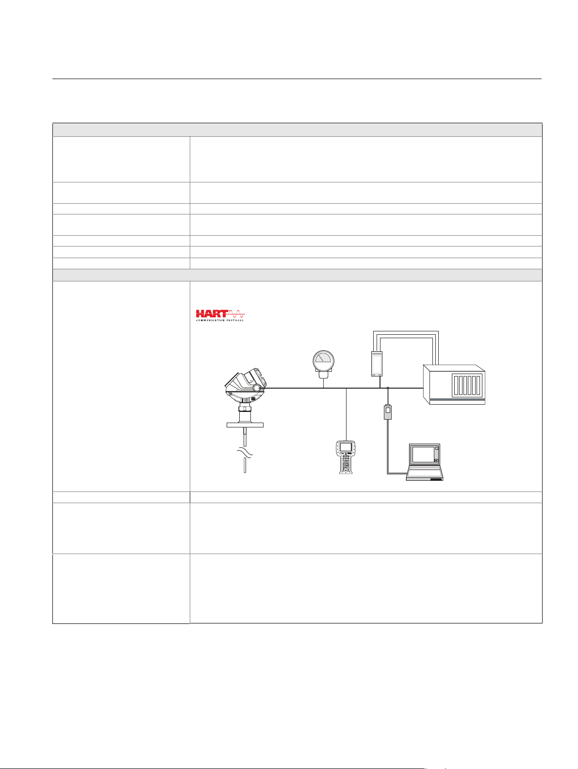
4-20 mA HART (Output Option Code H) - (See Ordering Information in Table 1 on page 4 and Table 2 on page 11)
Output Two-wire, 4–20 mA. Digital process variable is superimposed on 4–20 mA signal, and available to
(See “Measurement Principle” on page 2 for a description of how it works)
FCC part 15 (1998) subpart B and R&TTE (EU directive 99/5/EC). Considered to be an unintentional
radiator under the Part 15 rules
any host that conforms to the HART protocol. The HART signal can be used in a multidrop mode.
Signal Wiring Recommended output cabling is twisted shielded pairs, 18-12 AWG
HART Tri-loop By sending the digital HART signal to the optional HART Tri-loop, it is possible to
Smart Wireless THUM Adapter The optional Smart Wireless THUM adapter can be mounted directly on the
16
have up to three additional 4–20 mA analog signals. See the Rosemount 333
HART Tri-loop Product Data Sheet (Document No. 00813-0100-4754) for
additional information
transmitter or by using a remote mounting kit. IEC 62591 (WirelessHART) enables
access to multi-variable data and diagnostics, and adds wireless to almost any
measurement point. See the Rosemount Smart Wireless THUM adapter Product
Data Sheet (Document No. 00813-0100-4075) and Smart Wireless THUM Adapter
for Rosemount Process Level Transmitter Applications (Document No.
00840-0100-4026)

Product Data Sheet
The input voltage (UI) for HART is 16-42.4 Vdc
(16-30 Vdc in IS applications, and 20-42.4 Vdc
in Explosion-proof / Flameproof applications).
For Flameproof/Explosion-proof installations the
Rosemount 5300 Series transmitters have a
built-in barrier; no external barrier needed.
When a Smart Wireless THUM adapter is fitted,
it adds a maximum drop of 2.5 Vdc in the
connected loop
R
U
E
U
I
00813-0100-4530, Rev DA
December 2010
Rosemount 5300 Series
External Power Supply
Minimum Input Voltage (U
Different Currents
IS Parameters See “Product Certifications” on page 36
Signal on Alarm Standard: Low = 3.75 mA, High = 21.75 mA
Saturation Levels Standard: Low = 3.9 mA, High = 20.8 mA
(1)
R = Load Resistance (); UE = External Power Supply Voltage (Vdc); UI = Input Voltage (Vdc)
) at
I
Current: 3.75 mA
Non-Hazardous Installations and Intrinsically Safe Installations: 16 Vdc
Explosion-proof / Flameproof Installations: 20 Vdc
Current: 21.75 mA
Non-Hazardous Installations and Intrinsically Safe Installations: 11 Vdc
Explosion-proof / Flameproof Installations: 15.5 Vdc
Namur NE43: Low = 3.60 mA, High = 22.50 mA
Namur NE43: Low = 3.8 mA, High = 20.5 mA
17

Rosemount 5300 Series
Non-Hazardous Installations
Maximum Load Resistance
Operating
Region
External Power
Supply Voltage
Intrinsically Safe Installations
Operating
Region
Maximum Load Resistance
External Power
Supply Voltage
Explosion-proof / Flameproof (EEx d) Installations
Maximum Load Resistance
External Power
Supply Voltage
Operating
Region
NOTE
For the EEx d case, the diagram is only valid if the HART
®
load resistance is at the + side and
if the - side is grounded, otherwise the load resistance value is limited to 435 .
Load Limitations Maximum load resistance is determined by the voltage level of the external power supply, as
Product Data Sheet
00813-0100-4530, Rev DA
December 2010
described by:
18

Product Data Sheet
FOUNDATION™
fieldbus
Host / DCS system (e.g. DeltaV™)
Maintenance
H2 - High Speed
Field Bus
H1 - Low Speed
Field Bus
Field
Communicator
Rosemount 5301
6200 ft (1900 m)
max (depending
upon cable
characteristics)
Rosemount 5401
Rosemount 5601
PC with Rosemount
Radar Master
Fieldbus
Modem
Rosemount 752
Field Signal
Indicator
00813-0100-4530, Rev DA
December 2010
FOUNDATION™ fieldbus (Output Option Code F) - (See Ordering Information in Table 1 on page 4 and
Table 2 on page 11)
Output
Rosemount 5300 Series
External Power Supply
(1)
The input voltage for FOUNDATION™ fieldbus is 9-32 Vdc (9-30 Vdc in IS applications, and 16-32 Vdc
in Explosion-proof/Flameproof applications)
The input voltage for FISCO, IS applications is 9-17.5 Vdc
For Flameproof/Explosion-proof installations the Rosemount 5300 Series transmitters have a built-in
barrier; no external barrier needed.
Quiescent Current Draw 21 mA
OUNDATION fieldbus Blocks Resource block, 3 Transducer blocks, 6 AI blocks, PID block, ISEL block, SGCR block, ARTH block,
F
and OS block
OUNDATION fieldbus Class (Basic
F
Link Master (LAS)
or Link Master)
OUNDATION fieldbus Block
F
Execution Time
OUNDATION fieldbus Instantiation No
F
Conforming F
OUNDATION fieldbus PlantWeb
F
OUNDATION fieldbus ITK 5.0
AI-block: 30 ms. PID-block: 40 ms
ARTH-, ISEL-, OSPL-block: 65 ms. CHAR-block: 75 ms
Yes
Alert Support
19

Product Data Sheet
Rosemount 5300
Series Transmitter
HART
Modem
Power
Modbus, Levelmaster
Emulation / RS-485
Control
System
RS-232 / RS-485
Converter
Field Communicator
PC
5300 Setup in
Rosemount Radar
Master
PC
5300 Setup in
Rosemount Radar
Master via Tunneling
Power
Supply
RS-485 Bus
v
120
120
A
B
HART -
HART +
If it is the last
transmitter on the
bus, connect the
120
termination
resistor.
00813-0100-4530, Rev DA
Rosemount 5300 Series
Modbus (Output Option Code M) - (See Ordering Information in Table 1 on page 4 and Table 2 on page 11)
Output The RS-485 Modbus version communicates by Modbus RTU, Modbus ASCII, and Levelmaster
protocols.
8 data bits, 1 start bit, 1 stop bit, and software selectable parity.
Baud Rate: 1200, 2400, 4800, 9600 (default), and 19200 bits/s.
Address Range: 1 to 255 (default device address is 246).
HART communication is used for configuration via the HART terminals or tunneling via the RS-485.
December 2010
External Power Supply
(1)
The input voltage Ui for Modbus is 8-30 Vdc (max. rating)
Power Consumption:
< 0.5 W (with HART address=1)
< 1.2 W (incl. four HART slaves)
HART to Modbus Converter
MB
MA
MODBUS
(RS-485)
-
POWER
Ambients > 60 ºC
HART
Use wiring rated
for min 90 ºC
+
-
+
erter
MODBUS
(RS-485)
MB
MA
-
20
For Flameproof/Explosion-proof installations the Rosemount 5300 Series transmitters have a built-in
barrier; no external barrier needed.

Product Data Sheet
5301 5302 5303 PV, SV, TV, QV
Level XXX X
Distance to Level (Ullage) XXX X
Level Rate XXX X
Signal Strength XXX X
Volume XXX X
Internal Temperature XXX X
Interface Level (X)
(1)
(1) Interface measurement only for fully submerged probe, see page 25
XX
Interface Distance (X)
(1)
XX
Interface Level Rate (X)
(1)
XX
Interface Signal Strength (X)
(1)
XX
Upper Layer Thickness XX X
Lower Volume (X)
(1)
XX
Upper Volume (X)
(1)
XX
Signal Quality XXX(X)
(2)
(2) Not available as primary variable
Surface/Noise Margin XXX(X)
(2)
Vapor DC X(X)
(2)
Analog Output Current
(3)
(3) LCD variable only. Not available for FOUNDATION fieldbus, Modbus Signal Output, or
for HART units in fixed current mode
XXX
% of Range
(4)
(4) LCD variable only. Not available for FOUNDATION fieldbus Signal Output
XXX
00813-0100-4530, Rev DA
December 2010
Display and Configuration
Integral Display
(Options Code M1)
Remote Display Data can be read from the optional integral display or remotely using the Rosemount 751 Field Signal
Configuration Tools HART: Rosemount Radar Master, Emerson Field Communicator, AMS Device Manager, or any other
Output Units Level, Interface and Distance: ft, inches, m, cm, or mm
Output Variables
The integral digital display can toggle between: level, distance, volume, internal temperature,
interface distance, interface level, peak amplitudes, interface thickness, percentage of range, analog
current out
Note: The display cannot be used for configuration purposes
Indicator for 4-20 mA / HART (see Product Data Sheet, Document No. 00813-0100-4378), or the
Rosemount 752 Remote Indicator for F
Document No. 00813-0100-4377)
DD (Device Description) compatible host system
OUNDATION™ fieldbus: Rosemount Radar Master, Emerson Field Communicator, DeltaV, or any
F
other DD (Device Description) compatible host system
DTM (compliant with version 1.2 of the FDT/DTM specification) supporting configuration in for
instance Yokogawa Fieldmate/PRM, E+H™ FieldCare, and PactWare™
Level Rate: ft/s, m/s, in./min, m/h
Volume: ft
3
, inch3, US gals, Imp gals, barrels, yd3, m3, or liters
Temperature: °F and °C
Rosemount 5300 Series
OUNDATION™ fieldbus (see Product Data Sheet,
Diagnostics Transmitter diagnostics with alerts include hardware and software errors, electronics temperature,
probe missing, and invalid measurement and configuration error diagnostics. In addition to this, echo
curve and variable logging including signal strength facilitate easy on-line troubleshooting
Advanced Diagnostics Signal Quality Metrics monitors the degradation of level signal relative to excess noise.
This can schedule the cleaning of the probe or to detect and monitor turbulence, boiling, foam, and
Damping 0-60 s (2 s, default value)
emulsions. It can be ordered by choosing the D01 or DA1 option
21

Product Data Sheet
-320 (-196)
-40 (-40)
-40 (-40)
-17 (-27)
Ambient Temperature °F (°C)
Process Temperature °F (°C)
00813-0100-4530, Rev DA
Rosemount 5300 Series
Temperature and Pressure Limits
Ambient Temperature The maximum and minimum ambient temperature for the electronics depends on the process
temperature (as described by the graph below) and on the approval (see “Product Certifications” on
page 36).
Note:
• Nozzle insulation for the HTHP version (Operating Temperature and Pressure code H) should
not exceed 4 in. (10 cm)
• The temperature range for the optional Integral Display is -4 °F to 158 °F (-20 °C to 70 °C)
• In applications where the ambient temperature exceeds the limits of the electronics, a Remote
Mounting connection can be used. The maximum temperature for the Remote Mounting
connection at the vessel connection point is 302 °F (150 °C)
Storage Temperature -58 °F to 194 °F (-50 °C to 90 °C)
With Integral Display: -40 °F to 185 °F (-40 °C to 85 °C)
December 2010
22

Product Data Sheet
Pressure
psig (bar)
Temperature
°F (°C)
PTFE covered
probe and flange
(model code 7)
Max. Rating, Standard Connections
580 (40)
232 (16)
-14 (-1)
-40 (-40)
302 (150)
Max. Rating, HTHP Connections
5000 (345)
1000 (69)
752 (400)
2940 (203)
-14 (-1)
100 (38)
-76 (-60)
0
400 (204)
600 (316)
200 (93)
Temp.
°F (°C)
Pressure
psig (bar)
Max. Rating, HP Connections
Pressure
psig (bar)
Temperature
°F (°C)
5000 (345)
3524 (243)
3000 (206)
1000 (69)
-14 (-1)
-76 (-60)
0 100 (38)
200 (93)
392 (200)
00813-0100-4530, Rev DA
December 2010
Rosemount 5300 Series
Process Temperature
(2)
Standard (Std) tank connection (Operating Temperature and Pressure code S):
Final rating depends on flange and O-ring selection. The table on page 26 gives the temperature
ranges for standard tank seals with different O-ring materials.
High Temperature and High Pressure (HTHP) tank connection
(Operating Temperature and Pressure code H):
High Pressure (HP) tank connection (Operating Temperature and Pressure code P):
23

Rosemount 5300 Series
Max. Rating, C Connections
Pressure
psig (bar)
Temp.
°F (°C)
ASME / ANSI Flange Rating 316L SST flanges according to ASME B16.5 Table 2-2.3:
EN Flange Rating 1.4404 according to EN 1092-1 material group 13E0:
Fisher & Masoneilan Flange Rating 316L SST according to ASME B16.5 Table 2-2.3:
JIS Flange Rating 316L SST according to JIS B2220 material group 2.3:
Tri-Clamp Rating Maximum pressure is 16 bar for 1.5 in. (37.5 mm) and 2 in. (50 mm) housing; and 10 bar for 3 in. (75
Plate Design Certain models of flanged Alloy and PTFE covered probes have a tank connection design with a
Flange Connection Rating See Table 5 and Table 6 for the conditions used for flange strength calculations
Product Data Sheet
00813-0100-4530, Rev DA
December 2010
Cryogenic Temperature tank connection (Operating Temperature and Pressure code C):
-320 (-196)
-200 (-129)
• Standard: Max. 302 °F/580 psig (150 °C/40 Bar)
• HP/C: Class 2500 up to max 200 °C
• HTHP: Class 2500 up to max 400 °C
Alloy C-276 (UNS N10276) flanges according to ASME B16.5 Table 2-3.8:
• HP/C: Class 1500 up to max 200 °C
• HTHP: Class 1500 up to max 400 °C
• Standard: Max. 302 °F/580 psig (150 °C/40 Bar)
• HP/C: PN 320 up to max 200 °C
• HTHP: PN 320 up to max 400 °C
Alloy C-276 (UNS N10276) flanges according to EN 1092-1 material group 12E0
• Standard: Max. 302 °F/580 psig (150 °C/40 Bar)
• HP/C: Class 600 up to max 200 °C
• HTHP: Class 600 up to max 400 °C
• Standard: Max. 302 °F/580 psig (150 °C/40 Bar)
• HP/C: Max temp. 200 °C. Final rating depends on flange.
• HTHP: Max temp. 400 °C. Final rating depends on flange.
mm) and 4 in. (100 mm) housing. The final rating depends on the clamp and gasket. Tri-Clamp is
available for the Standard Temperature and Pressure seal.
protective flange plate of the same material as the probe and with a backing flange in 316L / EN
1.4404. The protective flange plate prevents the backing flange from being exposed to the tank
atmosphere.
Flange rating according to SST backing flange ASME B16.5 Table 2-2.3, EN 1092-1 material group
13E0, and JIS B2220 material group 2.3.
Alloy C-276 protective plate:
• Standard: Max. 302 °F/580 psig (150 °C/40 Bar). Flange plate design is available up to Class
300/PN 40
• HP: Max temp. 200 °C. Flange plate design is available up to Class 600/PN 63
• HTHP: Max temp. 400 °C. Flange plate design is available up to Class 600/PN 63
Alloy 400 protective plate:
• Standard: Max. 302 °F/580 psig (150 °C/40 Bar). Flange plate design is available up to Class
300/PN 40
PTFE protective plate:
• Standard: Max. 302 °F/580 psig (150 °C/40 Bar)
24

Product Data Sheet
Level
Interface Level
Level = Interface Level
5302
5301
Interface Measurement with a Rosemount 5302 and a
Rosemount 5301 (fully submerged probe)
00813-0100-4530, Rev DA
December 2010
Interface Measurements
Considerations The Rosemount 5302 is a good
choice for measuring the
interface of oil and water, or
other liquids with significant
dielectric differences. It is also
possible to measure interfaces
with a Rosemount 5301 in
applications where the probe is
fully submerged in the liquid. If
interface is to be measured,
follow these criteria:
• The dielectric constant
of the upper product
must be known and
should not vary. The
Radar Master software
has a built-in dielectric
constant calculator to
help the user estimate
the upper product dielectric constant
• The dielectric constant of the upper product must have a smaller dielectric constant than the
lower product
• The difference between the dielectric constants for the two products must be larger than 6
• The maximum dielectric constant for the upper product is 8 for the single lead probes, 10 for
the coaxial, and 7 for the twin lead probes
• The upper product thickness must be larger than 5.1 in. (0.13 m) for all probes, except the
HTHP coaxial probe, which requires 8 in. (0.2 m) to distinguish echoes from the two liquids
• Sometimes there is an emulsion layer (mix of the products) between the two products which
can affect interface measurements. For guidelines on emulsion situations, consult your local
Emerson Process Management representative
For information on the maximum allowable product thickness and measuring range, see “Interface
Measuring Range” on page 29.
Solids Measurements
Considerations Rosemount 5303 with a flexible single lead probe is a good choice for measuring solids, such as
powders, granulates, or pellets with a grain size of up to 0.8 in. (20 mm). The measurement is made
where the probe comes in contact with the material, which means that the shape of the material
surface is not critical for the measurement. Measurements are also independent of moisture and
material fluctuations such as density and temperature.
The following should be kept in mind:
• In solid applications, media may cause down-pull forces on silo roofs. The silo roof must be able
to withstand the probe collapse load, or at least the maximum probe tensile load
• The tensile load depends on the silo size, material density, and the friction coefficient. Forces
increase with the buried length, the silo, and probe diameter. In critical cases, such as products
with a risk of build-up, probe for high physical weight loads are available
• Forces on probes, depending on their position, are generally two to ten times greater on probes
with a tie-down than on probes with ballast weights
• For environments where electrostatic discharges (plastics) are likely to occur, grounding of the
probe and vessel may be required
Note:
Abrasive media can wear out the probe, so consider using non-contacting radar.
Rosemount 5300 Series
For more information, refer to the Guided Wave Radar in Solid Level Applications Technical Note
(Document No. 00840-2300-4811).
25

Rosemount 5300 Series
If a spool piece is
used, it is
important that the
reference reflector
is not positioned
where the spool
piece connects to
the chamber.
TABLE 4. Temperature ranges for standard tank seals with different O-ring materials
Tank seal with different
O-ring material
Min. Temperature
°F (°C) in air
Max. Temperature
°F (°C) in air
Viton
®
5 (-15) 302 (150)
Ethylene Propylene (EPDM) -40 (-40) 266 (130)
Kalrez
®
6375 14 (-10) 302 (150)
Buna-N -31 (-35) 230 (110)
NOTE!
Always check the chemical compatibility of the
o-ring material with your application
High Pressure Steam Applications
Considerations Saturated steam under high
pressure can influence radar
level transmitter measurements.
Rosemount 5301 with Dynamic
Vapor Compensation (DVC) will
automatically compensate for
this and maintain the level
accuracy.
Considerations for DVC:
• A Single lead rigid HTHP
probe with a reference
reflector for vapor
compensation must be used
(probe type 4U, 4V)
• Mount in a 2, 3, or 4-in
bypass chamber with
flanges appropriately sized
for the pressure and
temperature of the
application
• Use a centering disk to
keep the probe centered in
the chamber see “Chamber
/ Pipe Installations” on
page 34
• Probes up to 13.1 ft (4 m) in
length are supported
• Minimum measuring range is 12 in. (300 mm)
• DVC requires a minimum distance from the flange to the surface level in order to measure the
change in the vapor dielectric constant. If the level rises within this area, the unit switches over to
static compensation, using the last known vapor dielectric constant
For more information, refer to the High Pressure Steam Applications Technical Note (Document No.
00840-0100-4530)
(1) Reverse polarity protection.
(2) Final rating may be lower depending on flange and O-ring selection, See “Tank Connection and Probe” on page 31.
Minimum distance for dynamic
compensation up to level 100%:
17.3 in. (440 mm) for probes <6 ft. (2 m),
28 in. (710 mm) for probes >6 ft (2 m)
Level: 100%
Minimum measuring range:
12 in. (300 mm)
Level: 0%
Product Data Sheet
00813-0100-4530, Rev DA
December 2010
TABLE 5. 316L SST: conditions used for flange strength calculations
Bolting material Gasket Flange material Hub material
Standard/HTHP HP/HTHP/C
ASME /
ANSI
EN, JIS
26
Stainless steel SA193
B8M C1.2
EN 1515-1/-2 group
13E0, A4-70.
Soft (1a) with min.
thickness 1.6 mm.
Soft (EN 1514-1) with
min. thickness 1.6 mm.
Spiral wound gasket with
nonmetallic filler (1b)
Spiral wound gasket with
nonmetallic filler
Stainless steel A182
Gr. F316L and
EN 10222-5-1.4404.
(EN 1514-2)
Stainless steel A479M
316L, and
EN 10272-1.4404.

Product Data Sheet
Maximum Upper Product Thickness for the Flexible Twin
Lead Probe in ft (m)
Lower product
dielectric constant
Maximum upper product thickness
Upper product dielectric constant
Maximum Upper Product Thickness for the Flexible Single
Lead Probe in ft (m)
Maximum upper product thickness
Upper product dielectric constant
Lower product
dielectric constant
00813-0100-4530, Rev DA
December 2010
TABLE 6. Alloy C-276: conditions used for flange strength calculations
Bolting material Gasket Flange material Hub material
HP/HTHP/C
ASME /
ANSI
UNS N10276
EN, JIS
115 (35)
98 (30)
Soft (1a) with min.
Thickness 1.6 mm
Soft (EN 1514-1) with
min. Thickness 1.6 mm
Spiral wound gasket with
nonmetallic filler (1b)
Spiral wound gasket with
nonmetallic filler (EN
1514-2)
Rosemount 5300 Series
SB462 Gr. N10276
(solution annealed
condition) or SB575 Gr.
N10276 (solution
annealed condition)
SB574 Gr. N10276
82 (25)
66 (20)
49 (15)
33 (10)
16 (5)
0
1
35
80
40
20
10
7
11
9
27

Product Data Sheet
Upper Reference Point
Upper Transition Zone
Maximum
Measuring Range
Lower Transition Zone
Lower
Reference
Point
Lower Transition Zone
NOTE
The 4-20 mA set points are
recommended to be configured
between the transition zones,
within the measuring range
For a flexible single lead probe
with chuck, the lower transition
zone is measured upwards from
the upper clamp.
Lower Transition Zone
00813-0100-4530, Rev DA
Rosemount 5300 Series
Performance Specification
General
Reference Conditions Single standard probe, 77 °F (25 ° C) in water and ambient pressure
Reference Accuracy ± 0.12 in. (3 mm) or 0.03% of measured distance, whichever is greatest
Repeatability ± 0.04 in. (1 mm)
Ambient Temperature Effect ± 0.008 in. (0.2 mm) /°K or ± 30 ppm/°K of measured value, whichever is greatest
Update Interval < 1 per second
Measuring Range
Transition Zones Transition zones are areas where
measurements are non-linear or
have reduced accuracy. See
picture and Table 7 on page 29
If measurements are desired at the
very top of the tank, it is possible to
mechanically extend the nozzle
and use the coaxial probe. Then
the upper transition zone is moved
into the extension.
(1)
December 2010
28
Product Data Sheet
00813-0100-4530, Rev DA
December 2010
Rosemount 5300 Series
Measuring Range and
Minimum Dielectric Constant
Interface Measuring Range Target applications include interfaces between oil / oil-like and water / water-like liquids with low (<3)
16 in. (0.4 m) to 164 ft (50 m)
See Table 8 on page 30 for each probe’s measuring range and minimum dielectric constant. Due to
the measuring range depending on the application and factors described below, the values are a
guideline for clean liquids. For more information, ask your local Emerson Process Management
representative
Different parameters (factors) affect the echo and therefore the maximum measuring range differs
depending on application according to:
• Disturbing objects close to the probe
• Media with higher dielectric constant (
• Surface foam and particles in the tank atmosphere may affect measuring performance
• Heavy coating or contamination on the probe should be avoided since it can reduce measuring
range and might cause erroneous level readings
Note: For Remote Housing, see Table9 on page 30 for the maximum recommended measuring
range for different Remote Housing lengths, installation types, Dielectric Constants, and probe types
upper product dielectric constant and high (>20) lower product dielectric constant.
For such applications, the maximum measuring range is only limited by the length of the rigid single
lead, coaxial, and rigid twin probes.
For the flexible probes, the maximum measuring range will be reduced based on the maximum upper
product thickness according to the diagram below. The maximum interface distance is 164 ft (50 m)
minus the maximum product thickness.
For information on the maximum allowable product thickness and measuring range, see graphs on
page 27
) gives better reflection and allows a longer measuring range
r
Environment
Vibration Resistance Aluminum housing: IEC 60770-1 Level 1. Stainless Steel housing: IACS E10
Electromagnetic Compatibility Emission and Immunity: EMC directive 89/336/EEC. EN61326-1:1997 incl. A1:1998 and A2:2001.
NAMUR recommendations NE21
Built-in Lightning Protection EN61326, IEC 801-5, level 1 kV. T1 option: the transmitter complies with IEEE 587 Category B
Coating
(See Table 10 on page 30)
CE-mark Complies with applicable directives (EMC, ATEX)
(1) For probes with spacers, the accuracy may deviate close to the spacers. Accuracy may be affected by remote housing.
transient protection and IEEE 472 surge protection
• Single lead probes are preferred when there is a risk of contamination (because coating can result
in the product bridging across the two leads for twin versions; between the inner lead and outer
pipe for the coaxial probe)
• For viscous or sticky applications, PTFE probes are recommended. Periodic cleaning may also be
required
Signal Quality Metrics (option code D01, or DA1) can be used in determ ining when to clean the probe
•
Transmitters equipped with the Diagnostics Suite option can calculate Signal Quality Metrics
• Maximum error due to coating is 1-10% depending on probe type, dielectric constant, coating
thickness and coating height above product surface
TABLE 7. Transition Zones
Dielectric Constant Rigid Single Lead Flexible Single Lead Coaxial Rigid Twin Lead Flexible Twin Lead
(1)
Upper
Transition
Zone
(2)
Lower
Transition
Zone
Note: The 4–20 mA set points are recommended to be configured between the transition zones, within the measuring range.
(1) The distance from the upper reference point where measurements have reduced accuracy.
(2) The distance from the lower reference point where measurements have reduced accuracy.
(3) The measuring range for the PTFE covered Flexible Single Lead probe includes the weight. For low dielectri c media, special configuration may be required.
Note that the weight length or chuck fastening length adds to non-measurable area and is not included in the diagram. See “Dimensional Drawings” on page 39.
(4)
(5) When using a metallic centering disc, the lower transition zone is 8 in. (20 cm), including weight if applicable. When using a PTFE centering disc, th e lower
transition zone is not affected.
80 4.3 in. (11 cm) 4.3 in. (11 cm) 4.3 in. (11 cm) 4.3 in. (11 cm) 4.7 in. (12 cm)
2 6.3 in. (16 cm) 7.1 in. (18 cm) 4.3 in. (11 cm) 5.5 in. (14 cm) 5.5 in. (14 cm)
80 2 in. (5 cm) 0 in. (0 cm)
2 2.8 in. (7 cm)
(5)
2 in. (5 cm) - long
(4)
weight
3.2 in. (8 cm) - short
(4)
weight
(4) (3)
0.4 in. (1 cm) 1.2 in. (3 cm) 2 in. (5 cm)
2 in. (5 cm) 4 in. (10 cm) 5.5 in. (14 cm)
(4)
(4)
29

00813-0100-4530, Rev DA
Rosemount 5300 Series
TABLE 8. Measuring Range and Minimum Dielectric Constant
Rigid Single Lead Flexible Single Lead
9 ft. 10 in. (3 m)
164 ft (50 m) 19 ft 8 in. (6 m) 9 ft 10 in. (3 m) 164 ft (50 m)
for 8 mm probes.
14 ft. 9 in. (4.5 m)
for 13 mm probes
1.4 (Std)
(1.25 if installed in a
metallic bypass or
stilling well)
(1) (2)
1.4 (Std), up to 49 ft (15 m)
1.6 (HP/HTHP/C), up to 49 ft (15 m)
(Std/HP/HTHP/C)
1.8, up to 82 ft (25 m)
1.6 (HP/HTHP/C)
(1.4 if installed in a
metallic bypass or
stilling well)
(1) Probe end projection software function will improve the minimum measurable dielectric constant. Consult the factory for details.
(2) May be lower depending on installation.
(1) (2)
2.0, up to 115 ft (35 m)
3, up to 138 ft (42 m)
4, up to 151 ft (46 m)
6, up to 164 ft (50 m)
TABLE 9. Remote Housing Measuring Range
Dielectric
Constant
Chamber / pipe
1 m
Remote
Housing
installations ≤ 4 in.
(100 mm)
Tank installations
Chamber / pipe
2 m
Remote
Housing
installations ≤ 4 in.
(100 mm)
Tank installations
Chamber / pipe
3 m
Remote
Housing
(1) Accuracy may be affected up to + 1.2 in. (30 mm).
(2) Required chamber/pipe size is 3 or 4 in. (75 -100 mm).
installations ≤ 4 in.
(100 mm)
Tank installations
1.4
1.4
1.4
1.4
1.4
1.4
2
80
2
80
2
80
2
80
2
80
2
80
Rigid Single
4 ft (1.25 m)
10 ft (3 m)
10 ft (3 m)
4 ft (1.25 m)
4 ft (1.25 m)
10 ft (3 m)
9 ft (2.75 m)
10 ft (3 m)
10 ft (3 m)
9 ft (2.75 m)
9 ft (2.75 m)
10 ft (3 m)
10 ft (3 m)
(1)
Maximum Measuring Range
Minimum Dielectric Constant
(1)
(1)
1.2 (Std)
1.4 (HP/C)
2.0 (HTHP)
(1)
(1)
Rigid Single
8 mm
(1)
13 mm
15 ft (4.5 m)
15 ft (4.5 m)
15 ft (4.5 m)
4 ft (1.25 m)
4 ft (1.25 m)
(1)
10 ft (3 m)
15 ft (4.5 m)
(1)
15 ft (4.5 m)
15 ft (4.5 m)
9 ft (2.75 m)
9 ft (2.75 m)
(1)
10 ft (3 m)
15 ft (4.5 m)
15 ft (4.5 m)
15 ft (4.5 m)
14 ft (4.25 m)
14 ft (4.25 m)
15 ft (4.5 m)
Coaxial Rigid Twin Lead Flexible Twin Lead
1.4 (Std)
Flexible Single Coaxial Rigid Twin Flexible Twin
(1)
(1)
(1)
(1)
(1)
(1)
(1)
(1)
33 ft (10 m)
33 ft (10 m)
33 ft (10 m)
4 ft (1.25 m)
4 ft (1.25 m)
159 ft (48.5 m)
33 ft (10 m)
33 ft (10 m)
33 ft (10 m)
9 ft (2.75 m)
9 ft (2.75 m)
154 ft (47 m)
33 ft (10 m)
33 ft (10 m)
33 ft (10 m)
14 ft (4.25 m)
14 ft (4.25 m)
149 ft (45.5 m)
(1) (2)
(1) (2)
(1) (2)
(1) (2)
(1) (2)
(1) (2)
(1)
(1) (2)
(1) (2)
(1) (2)
10 ft (3 m)
10 ft (3 m)
19 ft
(6 m)
(1)
10 ft (3 m)
4 ft (1.25 m)
4 ft (1.25 m)
10 ft (3 m)
10 ft (3 m)
10 ft (3 m)
19 ft
(6 m)
10 ft (3 m)
9 ft (2.75 m)
9 ft (2.75 m)
10 ft (3 m)
19 ft
(6 m)
(1)
10 ft (3 m)
Product Data Sheet
December 2010
(Std)
1.4, up to 82 ft (25 m)
2.0, up to 115 ft (35 m)
2.5, up to 131 ft (40 m)
3.5, up to 148 ft (45 m)
6, up to 164 ft (50 m)
(1)
33 ft (10 m)
(1)
33 ft (10 m)
(1)
33 ft (10 m)
4 ft (1.25 m)
98 ft (30 m)
(1)
159 ft (48.5 m)
(1)
33 ft (10 m)
(1)
33 ft (10 m)
(1)
33 ft (10 m)
9 ft (2.75 m)
98 ft (30 m)
(1)
154 ft (47 m)
33 ft (10 m)
33 ft (10 m)
33 ft (10 m)
(1)
14 ft (4.25 m)
98 ft (30 m)
149 ft (45.5 m)
(1)
(1)
(1)
(1) (2)
(1) (2)
(1) (2)
(1)
(1)
(1) (2)
(1) (2)
(1) (2)
(1)
(1)
(1) (2)
(1) (2)
(1) (2)
(1)
(1)
TABLE 10. Maximum recommended Viscosity and Coating / Build-up
Coaxial Twin Lead Sing le Lead
Maximum Viscosity
500 cP 1500 cP 8000 cP
Coating / Build-up
Coating not
recommended
Thin coating
allowed, but no
Coating allowed
bridging
(1) Consult your local Emerson Process Management representative
in the case of agitation/turbulence and high viscous products.
(2) Be cautious in HTHP viscous or crystallizing media applications
where temperature at instrument connection is si gnif icantly lo wer
than process temperature with risk of coating in the upper part of
probe that may reduce the measurement signal. Consider using
HP or STD probes in such applications.
30
(1) (2)

Product Data Sheet
Remote Housing
Mounting Cable:
3, 6, or 9 ft (1, 2, or 3 m)
Tank seal with
protective plate
design
00813-0100-4530, Rev DA
December 2010
Rosemount 5300 Series
Physical Specification
Housing and Enclosure
Type Dual compartment (terminal compartment and the electronics are completely separated).
Two entries for conduit or cable connections. The transmitter housing can be rotated in any direction
Electrical Connection ½ - 14 NPT for cable glands or conduit entries.
Optional: M20 x 1.5 conduit / cable adapter, M12 4-pin male eurofast
male minifast
Housing Material Polyurethane-covered Aluminum, or Stainless Steel Grade CF8M (ASTM A743)
Ingress Protection NEMA 4X, IP 66, IP67
Factory Sealed Yes
Weight Transmitter Head (TH): Aluminium 4.4 lb (2 kg), SST 10.8 lb (4.9 kg).
Remote Housing Mounting Kit that includes a flexible armored extension
cable and a bracket for wall or pipe mounting.
See “Remote Housing” on page 50 for the
dimensions.
®
connector. Recommended output cabling is twisted shielded pairs, 18-12 AWG
®
connector or A size Mini 4-pin
Tank Connection and Probe
Tank Connection The tank connection consists of a tank seal, a
Flange Dimensions Follows ASME B 16.5, JIS B2220, and EN 1092-1 standards for blind flanges.
Vented Flanges Available with Masoneilan and Fisher vented flanges. Vented flanges must be ordered as
Probe Versions Coaxial, Rigid Twin and Rigid Single Lead, Flexible Twin and Flexible Single Lead. Probes can be
flange, Tri-Clamp, or NPT or BSP/G threads.
Certain models of flanged Alloy and PTFE
covered probes have a tank connection
design with a protective plate of the same
material as the probe. This is to prevent the
316L / EN 1.4404 SST flange from being
exposed to the tank atmosphere.
See “Dimensional Drawings” on page 39.
®
For Proprietary Fisher
Rings” on page 51
accessories with a 1½-in. NPT threaded process connection (code RA); see “Special Flanges and
Flushing Connection Rings” on page 51. As an alternative to a vented flange, it is possible to use a
flushing connection ring on top of the standard nozzle.
ordered in different materials and options for extreme temperatures and pressure
For guidelines on which probe to select depending on application, see the Technical Note Guided
Wave Radar Application Guidelines (Document No. 00840-2600-4811)
and Masoneilan® flanges, see “Special Flanges and Flushing Connection
31

Rosemount 5300 Series
Total
Probe
Length
NPT
BSP/G
Flange
Tri-Clamp
Upper
Reference
Point
Product Data Sheet
00813-0100-4530, Rev DA
December 2010
Material Exposed To
Tank Atmosphere
Pressure Equipment Directive (PED)
Total Probe Length This is defined from the upper reference point to the end of the probe (weight included, if applicable).
Standard Probe (Operating Temperature and Pressure code S):
• Material model code 1: 316L SST (EN 1.4404), PTFE, PFA, and O-ring materials
• Material model code 2: Alloy C-276 (UNS N10276), PTFE, PFA, and O-ring materials
• Material model code 3: Alloy 400 (UNS N04400), PTFE, PFA, and O-ring materials
• Material model code 7: PTFE
• Material model code 8: PTFE, 316 L SST (EN 1.4404), and O-ring materials
HTHP Probe (Operating Temperature and Pressure code H):
• Material model code 1: 316L SST (EN 1.4404), Ceramic (Al2O3), Graphite, and Inconel
• Material model code 2 and H: Alloy C-276 (UNS N10276), Ceramic (Al2O3), Graphite, Inconel
HP Probe (Operating Temperature and Pressure code P):
• Material model code 1: 316L SST (EN 1.4404), Ceramic (Al2O3), Graphite, PFA, PTFE, Inconel
• Material model codes 2, H: Alloy C-276 (UNS N10276), Ceramic (Al2O3), Graphite, PFA, PTFE,
Inconel
Cryogenic Probe (Operating Temperature and Pressure code C):
• Material model code 1: 316L SST (EN 1.4404), Ceramic (Al2O3), Graphite, PFA, PTFE, Inconel
Complies with 97/23/EC article 3.3
Select the probe length according to the required measuring range (the probe must be hung and fully
extended through the entire distance where level readings are desired).
Most of the probes can be cut in field. However, there are some restrictions for the standard and
HP/C coaxial probes: these can be cut up to 2 ft. (0.6 m). Probes shorter than 4.1 ft. (1.25 m) can be
cut to the minimum length of 1.3 ft. (0.4 m). The HTHP coaxial probe and the PTFE covered probes
cannot be cut in the field.
Minimum and Maximum Probe
Length
Probe Angle 0 to 90 degrees from vertical axis
Tensile Strength 0.16 in. (4 mm) Flexible Single Lead probe: 2698 lb (12 kN)
Collapse Load 0.16 in. (4 mm) Flexible Single Lead probe: 3597 lb (16 kN)
Sideway Capacity Coaxial probe: 73.7 ft. lbf, 3.7 lb at 19.7 ft. (100 Nm, 1.67 kg at 6 m)
Maximum Recommended Nozzle
Height
Coaxial: 1.3 ft (0.4 m) to 19.7 ft (6 m).
Rigid Twin Lead: 1.3 ft (0.4 m) to 9.8 ft (3 m).
Flexible Twin Lead: 3.3 ft (1 m) to 164 ft (50 m).
Rigid Single Lead (0.3 in./8 mm): 1.3 ft (0.4 m) to 9.8 ft (3 m)
Rigid Single Lead (0.5 in./13 mm): 1.3 ft (0.4 m) to 14.8 ft (4.5 m)
Flexible Single Lead: 3.3 ft (1 m) to 164 ft (50 m)
0.24 in. (6 mm) Flexible Single Lead probe: 6519 lb (29 kN)
Flexible Twin Lead probe: 2023 lb (9 kN)
0.24 in. (6 mm) Flexible Single Lead probe: 7868 lb (35 kN)
Rigid Twin Lead: 2.2 ft. lbf, 0.22 lb at 9.8 ft. (3 Nm, 0.1 kg at 3 m)
Rigid Single Lead: 4.4 ft. lbf, 0.44 lb at 9.8 ft. (6 Nm, 0.2 kg at 3 m)
4 in. (10 cm) + nozzle diameter
For coaxial probes, there are no restrictions
32

Product Data Sheet
Nozzle
Height
Long Stud
(9.8 in./250 mm)
When using single flexible probes
in tall and narrow nozzles, a Long
Stud (LS option) i s rec om me n ded
to prevent the probe from
contacting the nozzle
Nozzle Diameter
Clearance to
tank wall
Avoid direct contact
Flexible single
lead probe with
chuck installed in
liquids and in
solids.
For solids, it is
recommended
that the probe
should be slack
to prevent high
tensile loads.
00813-0100-4530, Rev DA
December 2010
Minimum Clearance
(See Table 11 on page 35)
Rosemount 5300 Series
Other Mechanical Considerations To get best possible performance, the
Weight Flange: depends on flange size
following must be considered before
installing the transmitter:
• Inlets should be kept at a distance in
order to avoid product filling on the
probe
• Avoid physical contact between
probes and agitators, as well as
applications with strong fluid
movement unless the probe is
anchored
• Probe tie-down is recommended if
the probe can move to within 1 ft. (30
cm) of any object during operations
• In order to stabilize the probe for side
forces, it is possible to fix or guide
the probe to the tank bottom
• For optimal single lead probe performance in non-metallic vessels, the probe must either be
mounted with a 2-in. / DN 50 or larger metallic flange, or a metal sheet with an 8-in. diameter
(200 mm) or larger must be used (see the Reference Manual for placement)
See the Reference Manual (Document No. 00809-0100-4530) for more mechanical installation
information
Coaxial probe: 0.67 lb/ft (1 kg/m)
Rigid Single Lead probe (0.3 in./8 mm): 0.27 lb/ft (0.4 kg/m)
Rigid Single Lead probe (0.5 in./13 mm): 0.71 lb/ft (1.06 kg/m)
Rigid Twin Lead probe: 0.40 lb/ft (0.6 kg/m)
Flexible Single Lead probe: 0.05 lb/ft (0.08 kg/m)
Flexible Twin Lead probe: 0.09 lb/ft (0.14 kg/m)
End weight: 0.88 lb (0.40 kg) for the 4 mm single lead probe, 1.2 lb (0.55 kg) for the 6 mm single lead
probe and 1.3 lb (0.60 kg) for twin lead probes
33

Rosemount 5300 Series
Centre-to-Centre
Centre-to-Centre
Side-and-Side
dimension
Side-and-Bottom
dimension
Replace
chamber
flange
Displacer
Length
Probe
Length
Chamber / Pipe Installations
Rosemount 9901 Chamber Rosemount 9901 allows external mounting
of process level instrumentation. It supports
a variety of process connections, and
optional drain and vent connections. The
Rosemount 9901 chamber is designed to
the ASME B31.3 standard, and is Pressure
Equipment Directive (PED) compliant. Use
option code XC to order together with the
5300 Series transmitters.
The probe length to use for a Rosemount
9901 chamber can be calculated with this
formula (only valid for standard 9901
chambers):
Side-and-Side dimension:
Probe length=Centre-to-Centre
dimension+19 in. (48 cm)
Side-and-Bottom dimension:
Probe length=Centre-to-Centre
dimension+4 in. (10 cm)
Use a centering disc the same diameter as the chamber if the probe length >3.3 ft (1 m). See “Probe
Type in Chamber Considerations” on page 34 and “Centering Discs” on page 35 for which probe and
disc to use
For additional information, see the Rosemount 9901 Chamber for Process Level Instrumentation
Product Data Sheet (Document Number 00813-0100-4601)
Existing Chamber A Rosemount 5300 Series transmitter is the perfect
replacement in an existing displacer chamber.
Proprietary flanges are offered, enabling use of
existing chambers to make installation easy.
Considerations when changing to 5300:
The 5300 series flange choice and probe length
must be correctly matched to the chamber. Both
standard ANSI and EN (DIN), as well as proprietary
chamber flanges, are available. See “Special
Flanges and Flushing Connection Rings” on
page 51 to identify the proprietary flanges.
Product Data Sheet
00813-0100-4530, Rev DA
December 2010
Probe Type in Chamber
Considerations
34
See “Probe Type in Chamber Considerations” on
page 34 and “Centering Discs” on page 35 for which
probe and disc to use. See Table 12 on page 35 for
guidelines on the required probe length
For additional information, see the Replacing Displacers with Guided Wave Radar Technical Note
(Document Number 00840-2200-4811)
When installing a Rosemount 5300 in a chamber, the single lead probe is recommended. An
exception is with liquefied gas > 40 bar where the coaxial probe is recommended.
The recommended minimum chamber diameter is 4 in. (100 mm) for Single Flexible probe and 3 in.
(75 mm) for the Single Rigid probe. The probe should be centered to prevent it touching the sides of
the well.
The probe length determines if a Single Rigid or Single Flexible probe should be used:
• Less than 20 ft (6 m):
Rigid Single Probe is recommended. Use a centering disc for probe > 3.3 ft (1 m). If installation
requires less head-space, use a Flexible Single Probe with a weight and centering disc.
• More than 20 ft (6 m):
Use Flexible Single Probe with a weight and centering disc.
A short weight is available for the single flexible SST probe. It is used for measuring close to the
probe end and shall be used where the measuring range must be maximized. The height is 2 in. (50
mm) and the diameter is 1.5 in. (37.5 mm). The option code is W2.

Product Data Sheet
D
00813-0100-4530, Rev DA
December 2010
Centering Discs To prevent the probe from contacting the chamber or pipe wall, centering discs
are available for rigid single, flexible single, and flexible twin lead probes. The
disc is attached to the end of the probe. Discs are made of stainless steel, Alloy
C-276, Alloy 400, or PTFE. The centering disc in PTFE is not available for
HTHP probes. See Table 13 for Dimension D. Table 14 shows which centering
disc diameter to choose for a particular pipe.
TABLE 11. Minimum Clearance
Rigid Single Lead Flexible Single Lead Coaxial Rigid Twin Lead Flexible Twin Lead
Recommended
nozzle diameter
Min. nozzle
diameter
(1)
Min. clearance to
tank wall (L) or
obstruction
(2)
Min. chamber/still
pipe diameter
(1) Requires special configuration and setting of Upper Null Zone and may affect the maximum measuring range.
(2) Minimum clearance from tank bottom for the coaxial and rigid single probes is 0.2 in. (5 mm).
(3) The probe must be centered in the pipe/bypass. A centering disc (see “Centering Discs” on page 35 and “Ordering Information” on page 4) can be used to
prevent the probe from contacting the chamber wall.
(4) The centermost lead must be at least 0.6 in. (15 mm) away from the pipe/bypass wall.
6 in. (15 cm) or more 6 in. (15 cm) or more
2 in. (5 cm) 2 in. (5 cm)
4 in. (10 cm) if
smooth metallic wall.
20 in. (50 cm) if
disturbing objects,
rugged metallic or
concrete/plastic wall.
(3)
2 in. (5 cm)
Consult the factory 1.5 in. (3.8 cm) 2 in. (5 cm)
4 in. (10 cm) if
smooth metallic wall.
20 in. (50 cm) if
disturbing objects,
rugged metallic or
concrete/plastic wall.
Enough space to fit
the probe
Enough space to fit
the probe
0 in. (0 cm) 4 in. (10 cm) 4 in. (10 cm)
Rosemount 5300 Series
4 in. (10 cm) or more 4 in. (10 cm) or more
2 in. (5 cm) 2 in. (5 cm)
(4)
Consult the factory
TABLE 12. Required probe length in chambers
Chamber Manufacturer Probe Length
Major torque-tube manufacture
Displacer+9 in. (229 mm)
(249B, 249C, 2449K, 249N, 259B)
Masoneilan (Torque tube
Displacer+8 in. (203 mm)
operated), proprietary flange
Other - torque tube
(2)
Magnetrol (spring operated)
(3)
Displacer+8 in. (203 mm)
Displacer+between
7.8 in. (195 mm) to
15 in. (383 mm)
Others - spring operated
(2)
Displacer+19.7 in.
(500 mm)
(1) If flushing ring is used, add 1 in. (25 mm).
(2) For other manufacturers, there are small variations. This is an
approximate value, actual length should be verified.
(3) Lengths vary depending on model, SG and rating, and should be
verified.
(1)
TABLE 13. Centering Disc Dimensions
Disc Size Actual Disc Diameter
2 in. 1.8 in. (45 mm)
3 in. 2.7 in. (68 mm)
4 in. 3.6 in. (92 mm)
6 in. 5.55 in. (141 mm)
8 in. 7.40 in. (188 mm)
TABLE 14. Centering disc size
recommendation for different pipe schedules
Pipe Schedule
Pipe Size 5s,5 10s,10 40s,40 80s,80 120 160
2 in. 2 in. 2 in. 2 in. 2 in. NA
3 in. 3 in. 3 in. 3 in. 3 in. NA
4 in. 4 in. 4 in. 4 in. 4 in. 4 in. 3 in.
5 in. 4 in. 4 in. 4 in. 4 in. 4 in. 4 in.
6 in. 6 in. 6 in. 6 in. 6 in. 4 in. 4 in.
7 in. NA
(1)
NA
(1)
5 in. 6 in. NA
8 in. 8 in. 8 in. 8 in. 8 in. 6 in. 6 in.
(1) Schedule is not available for pipe size.
(2) No centering disc is available.
(1)
(1)
(1)
NA
2 in.
NA
(2)
(1)
35

Rosemount 5300 Series
Product Certifications
Product Data Sheet
00813-0100-4530, Rev DA
December 2010
SAFETY NOTE
A safety isolator such as a zener barrier is always needed for
intrinsic safety.
Probes covered with plastic and/or with plastic discs may generate
an ignition-capable level of electrostatic charge under certain
extreme conditions. Therefore, when the probe is used in a
potentially explosive atmosphere, appropriate measures must be
taken to prevent electrostatic discharge.
Factory Mutual (FM) Approval
Project ID: 3020497
E5 Explosion-proof for Class I, Div. 1,
Groups B, C, and D;
Dust Ignition Proof for Class II/III, Div. 1, Groups E, F, and G;
With Intrinsically Safe connections to
Class I, II, III, Div. 1, Groups B, C, D, E, F, and G.
Temp. Code T4
Ambient temperature limits: -50 °C to +70 °C
(3)
.
Seal not required.
Approval valid for HART, F
OUNDATION fieldbus, and Modbus
options.
I5, IE Intrinsically Safe for Class I, II, III, Div. 1, Groups A, B, C, D,
E, F, and G,
Class I, Zone 0, AEx ia IIC T4 when installed per Control
Drawing: 9240 030-936.
Non-Incendive Class I, II, Div. 2, Groups A, B, C, D, F, and G;
Suitable for Class III, Div. 2.
4-20 mA / HART model: U
C
=7.26 nF, Li=0 H.
i
OUNDATION fieldbus model: U
F
=1.3 W, Ci=0 nF, Li=0 H.
P
i
FISCO model: U
=17.5 Vdc, Ii=380 mA, Pi=5.32 W, Li=Ci=0.
i
Temp. Code T4
Ambient temperature limits: -50 °C to +70 °C
=30 Vdc, Ii=130 mA, Pi=1.0 W,
i
=30 Vdc, Ii=300 mA,
i
(3)
Approval valid for HART, FOUNDATION fieldbus, and FISCO
options.
EU Conformity
The most recent revision of the EC declaration of conformity
can be found at www.rosemount.com
.
ATEX Approval
Nemko 04ATEX1073X
SPECIAL CONDITIONS FOR SAFE USE (X)
The intrinsically safe circuits do not withstand the 500 Vac test as
specified in IEC 60079-11 clause 6.4.12.
Impact and friction hazards need to be considered according to
EN 60079-0 clause 8.1.2 when the transmitter and part of
antennas exposed to the exterior atmosphere of the tank is made
with light metal alloys and of category II 1G EPL Ga.
The Ex ia version of model 5300 FISCO field device may be
supplied by an [Ex ib] FISCO power supply when the power supply
is certified with three separate safety current limiting devices and
voltage limitation which meets the requirements for type Ex ia.
(1)
E1
Flameproof:
II 1/2 G T4
II 1D T79°C
Ex ia/db ia IIC T4 Ga/Gb (-40 °CT
Ex ta IIIC T79°C
m = 250 V.
U
Approval valid for HART, F
options.
(1)
(1)
, IA
I1
Intrinsically Safe:
II 1 G T4.
II 1/2 G T4
II 1 D T79°C
Ex ia IIC T4 (-50 °CTa+70 °C
Ex ia/ib IIC T4 Ga/Gb (-50 °CT
Ex ta IIIC T79°C
4-20 mA / HART model: U
=7.26 nF, Li=0 H.
C
i
OUNDATION fieldbus model: U
F
P
=1.5 W, Ci=0 nF, Li=0 H.
i
FISCO model: U
<1 μH.
L
i
Installation Drawing: 9240 030-938
Approval valid for HART, F
options.
(2)
.
(2)
(-40 °CTa+70 °C
OUNDATION fieldbus, and Modbus
(2)
(2)
(-50 °CTa+70 °C
=30 Vdc, Ii=130 mA, Pi=1.0 W,
i
=17.5 Vdc, Ii=380 mA, Pi=5.32 W, Ci=0 nF,
i
OUNDATION fieldbus, and FISCO
a
(3)
).
+70 °C
a
=30 Vdc, Ii=300 mA,
i
+70 °C
(3)
)
(3)
(3)
).
(3)
)
).
Safety Instrumented Systems (SIS)
The Rosemount 5300 Series has been evaluated by a third
party, Exida, against hardware requirements according to
IEC 61508. With a FMEDA (Failure Modes, Effects and
Diagnostics Analysis) report with a Safe Failure Fraction
(SFF) above 90%, 5300 is suitable in SIS according to the
Prior Use methodology. For more information, go to:
http://www.emersonprocess.com/rosemount/safety/. To
order the certificate of FMEDA data use option code QS.
36
(1) Ordering Information Code for Product Certificates, see page 8 and page 13.
(2) +69 °C with F
(3) +60 °C with F
OUNDATION fieldbus or FISCO option.
OUNDATION fieldbus or FISCO option.

Product Data Sheet
00813-0100-4530, Rev DA
December 2010
Rosemount 5300 Series
Canadian Standards Association (CSA) Approval
This product meets the Dual Seal Requirements of
ANSI/ISA 12.27.01-2003.
Cert. no. 1514653
(1)
Explosion-proof with internal Intrinsically Safe Circuits [Exia]
E6
Class I, Div. 1, Groups B, C and D;
Temp Code T4.
Class II, Div. 1 and 2, Groups E, F and G;
Class III, Div. 1
Ambient temperature limits -50 °C to +70 °C
Approval valid for HART, FOUNDATION fieldbus, and Modbus
options.
(1)
Intrinsically Safe Exia:
I6, IF
Class I, Div. 1, Groups A, B, C, and D.
Temp Code T4.
4-20 mA / HART model: U
=7.26 nF, Li=0 H.
C
i
OUNDATION fieldbus model: U
F
=1.3 W, Ci=0 nF, Li=0 H.
P
i
FISCO model: U
=17.5 Vdc, Ii=380 mA, Pi=5.32 W, Li=Ci=0.
i
Approval valid for HART, F
=30 Vdc, Ii=130 mA, Pi=1.0 W,
i
=30 Vdc, Ii=300 mA,
i
OUNDATION fieldbus, and FISCO
options.
Installation Drawing: 9240 030-937
Ambient temperature limits -50 °C to +70 °C
(3)
(3)
IECEx Approval
IECEx NEM 06.0001X
SPECIAL CONDITIONS FOR SAFE USE (X)
The intrinsically safe circuits do not withstand the 500 Vac test as
specified in IEC 60079-11 clause 6.4.12.
Impact and friction hazards need to be considered according to
EN 60079-0 clause 8.1.2 when the transmitter and part of
antennas exposed to the exterior atmosphere of the tank is made
with light metal alloys and of category II 1G EPL Ga.
The Ex ia version of model 5300 FISCO field device may be
supplied by an [Ex ib] FISCO power supply when the power supply
is certified with three separate safety current limiting devices and
voltage limitation which meets the requirements for type Ex ia.
(1)
Flameproof:
E7
Ex ia/db ia IIC T4 Ga/Gb (-40 °C T
Ex ta IIIC T79°C
m = 250 V.
U
(2)
(-40 °C Ta +70 °C
Approval valid for HART, F
options.
(1)
(1)
, IG
I7
Intrinsically Safe:
Ex ia IIC T4 (-50 °CT
Ex ia/ib IIC T4 Ga/Gb (-50 °CT
Ex ta IIIC T79°C
(2)
(-50 °CTa+70 °C
4-20 mA / HART model: U
=7.26 nF, Li=0 H.
C
i
F
OUNDATION fieldbus model: U
=1.5 W, Ci=0 nF, Li=0 H.
P
i
FISCO model: U
L
<1 μH.
i
Installation Drawing: 9240 030-938
=17.5 Vdc, Ii=380 mA, Pi=5.32 W, Ci=0 nF,
i
Approval valid for HART, F
options.
+70 °C
a
OUNDATION fieldbus, and Modbus
(3)
+70 °C
a
).
+70 °C
a
(3)
=30 Vdc, Ii=130 mA, Pi=1.0 W,
i
=30 Vdc, Ii=300 mA,
i
OUNDATION fieldbus, and FISCO
(3)
)
(3)
)
(3)
).
).
(1) Ordering Information Code for Product Certificates, see page 8 and page 13.
(2) +69 °C with F
(3) +60 °C with F
OUNDATION fieldbus or FISCO option.
OUNDATION fieldbus or FISCO option.
37

Rosemount 5300 Series
Product Data Sheet
00813-0100-4530, Rev DA
December 2010
National Supervision and Inspection Center
for Explosion Protection and Safety of
Instrumentation (NEPSI) Approvals
SPECIAL CONDITIONS FOR SAFE USE (X)
Refer to Certificates:
GYJ081080X for Ex ia ll C T4 and GYJ081130X for Ex iad ll C T4.
(1)
Flameproof:
E3
HART model:
Ex iad IIC T4 (-40 °C<T
OUNDATION fieldbus model:
F
Ex iad IIC T4 (-40 °C<T
(1)
Intrinsically Safe:
I3
HART model:
Ex ia IIC T4 (-50 °C<T
4-20 mA / HART model: U
=7.25 nF, Li=108 H
C
i
OUNDATION fieldbus model:
F
Ex ia IIC T4 (-50 °C<Ta< +60 °C)
=30 V, Ii=300 mA, Pi=1.5 W, Ci0 nF, Li0 H
U
i
(1)
FOUNDATION fieldbus FISCO model:
IC
Ex ia IIC T4 (-50 °C<Ta< +60 °C)
=17.5 V, Ii=380 mA, Pi=5.32 W, Ci0 nF, Li~0 H
U
i
<+70 °C)
a
<+60 °C)
a
<+70 °C)
a
=30 V, Ii=130 mA, Pi=1.0 W,
i
T echnology Institution of Indu strial Safety
(TIIS) Approval
(1)
E4
Flameproof:
Transmitter: Ex d [ia] IIC T4
Probe: Ex ia IIC T4
Installation Drawing: 05300-00548.
Approval valid for HART and F
For detailed information, refer to the Rosemount 5300 Series
Reference Manual (Document No. 00809-0100-4530).
OUNDATION fieldbus options.
NCC/INMETRO Approvals
SPECIAL CONDITIONS FOR SAFE USE (X)
Refer to Certificate:
4205/07X
E2 Flameproof:
BR-Ex d/ia IIC T4 -40 °CT
Approval valid for HART and F
a
(2)
+70 °C
Gb/Ga
OUNDATION fieldbus options.
I2, IB Intrinsically Safe:
(2)
BR-Ex ia IIC T4 -40 °CT
Approval valid for HART and F
+70 °C
a
Ga
OUNDATION fieldbus options.
Overfill Protection
Cert no: Z-65.16-476
U1 TÜV-tested and approved for overfill protection according to
the German WHG regulations
Approval valid for HART option.
(1) Ordering Information Code for Product Certificates, see page 8 and page 13.
(2) +60 °C with F
OUNDATION fieldbus.
38

Product Data Sheet
5.2 (133)
7.1 (180)
3.4 (87) 3.6 (92)
7.4 (188.5)
10.1 (257.5)
Ø 0.31 (8) or 0.51 (13):
SST probe
Ø 0.47 (12):
PTFE covered probe
½ - 14 NPT
Optional
adapters:
M20x1.5,
eurofast and
minifast
L 10 ft. (3 m)
for Ø 0.31 (8)
L
20 ft. (6 m)
for Ø 0.51 (13)
PTFE covered
probe and
protective plate
Alloy probe and
protective plate
The PTFE and
Alloy probes are
designed with a
protective plate.
HTHP/HP/C version
15.6 (397.5)
15.6 (397.5)
HTHP/HP Plate Design
(Option for Alloy versions)
00813-0100-4530, Rev DA
December 2010
Rosemount 5300 Series
Dimensional Drawings
RIGID SINGLE LEAD PROBE WITH FLANGE CONNECTION
Dimensions are in inches
(millimeters)
39

Rosemount 5300 Series
PTFE covered probe
and protective plate
L 10 ft. (3 m) for Ø 0.31 (8)
L
20 ft. (6 m) for Ø 0.51 (13)
7.1 (180)
3.4 (87)
3.6 (92)
½ - 14 NPT
Optional
adapters:
M20x1.5,
eurofast and
minifast
Ø 0.31 (8) or 0.51 (13): SST probe
Ø 0.47 (12): PTFE covered probe
5.2 (133)
7.4 (188.5)
10.1 (257.5)
10.1 (257.5)
Product Data Sheet
00813-0100-4530, Rev DA
December 2010
RIGID SINGLE LEAD PROBE WITH TRI-CLAMP CONNECTION
Dimensions are in inches
(millimeters)
40

Product Data Sheet
NPT 1/1½/2 inch NPT 1/1½/2 inch
5.2 (133)
2.4 (62)
7.1 (180)
1 in. / 1½ in.: s52
2 in.: s60
3.6 (92)3.4 (87)
Ø 0.31 (8) or 0.51 (13): SST probe
Ø 0.47 (12): PTFE covered probe
7.4 (188.5)
10.1 (257.5)
½ - 14 NPT
Optional
adapters:
M20x1.5,
eurofast and
minifast
L 10 ft. (3 m) for Ø 0.31 (8)
L
20 ft. (6 m) for Ø 0.51 (13)
3.4 (87)
1.1 (27)
7.1 (180)
3.6 (92)
L
10 feet (3 m)
HTHP/HP/C version
15.6 (397.5)
10.1 (257.5)
Ø 0.31 (8) or 0.51 (13): SST probe
Ø 0.47 (12): PTFE covered probe
G 1/1½ inch
NPT 1½, G 1½ inch
NPT: s50
G: s60
1 in.: s52
1½ in.: s60
00813-0100-4530, Rev DA
December 2010
Rosemount 5300 Series
RIGID SINGLE LEAD PROBE WITH THREADED CONNECTION
Dimensions are in inches
(millimeters)
41

Rosemount 5300 Series
5.2 (133)
7.1 (180)
3.4 (87) 3.6 (92)
L
164 feet (50 m)
7.4 (188.5)
10.1 (257.5)
Ø 0.16 (4): SST probe
Ø 0.24 (6): SST probe
Ø 0.28 (7): PTFE
covered probe
5.5 (140): 4 and 6 mm SST
probes
17.1 (434): PTFE covered
probe
0.86 (22): 4 mm SST probe
0.88 (22.5): PTFE covered probe
1.10 (28): 6 mm SST probe
½ - 14 NPT
Optional
adapters:
eurofast and
minifast
A
B
The PTFE covered
probe is designed with
a protective plate.
Short weight (option W2)
A: 2 (50); 4 mm SST probes
B: 1.5 (37.5); 4 mm SST probes
Long weight (option W3)
A: 5.5 (140); 4 mm SST probes
B: 1.5 (37.5); 4 mm SST probes
15.6 (397.5)
HTHP/HP/C version
HTHP/HP/C Plate Design
(Option for Alloy versions)
15.6 (397.5)
Product Data Sheet
00813-0100-4530, Rev DA
December 2010
FLEXIBLE SINGLE LEAD PROBE WITH FLANGE CONNECTION
Dimensions are in inches
(millimeters)
42

Product Data Sheet
7.1 (180)
3.4 (87) 3.6 (92)
½ - 14 NPT
Optional
adapters:
eurofast and
minifast
L 164 feet (50 m)
Ø 0.16 (4): SST probe
Ø 0.24 (6): SST probe
Ø 0.28 (7): PTFE
covered probe
5.2 (133)
7.4 (188.5)
5.5 (140): 4 and 6 mm SST
probes
17.1 (434): PTFE covered
probe
A
B
The PTFE covered probe
is designed with a
protective plate.
10.1 (257.5)
0.86 (22): 4 mm SST probe
0.88 (22.5): PTFE covered probe
1.10 (28): 6 mm SST probe
Short weight (option W2)
A: 2 (50); 4 mm SST probes
B: 1.5 (37.5); 4 mm SST probes
Long weight (option W3)
A: 5.5 (140); 4 mm SST probes
B: 1.5 (37.5); 4 mm SST probes
00813-0100-4530, Rev DA
December 2010
Rosemount 5300 Series
FLEXIBLE SINGLE LEAD PROBE WITH TRI-CLAMP CONNECTION
Dimensions are in inches
(millimeters)
43

Rosemount 5300 Series
5.5 (140): 4 and 6 mm
SST probes
17.1 (434): PTFE
covered probe
5.2 (133)
2.4 (62)
7.1 (180)
1 in. / 1½ in.: s52
2 in.: s60
3.6 (92)
3.4 (87)
L
164 feet
(50 m)
0.86 (22): 4 mm SST probe
0.88 (22.5): PTFE covered probe
1.10 (28): 6 mm SST probe
10.1 (257.5)
½ - 14 NPT
Optional
adapters:
M20x1.5,
eurofast and
minifast
NPT 1/1½/2 inch NPT 1/1½/2 inch
7.4 (188.5)
A
B
Short weight (option W2)
A: 2 (50); 4 mm SST probes
B: 1.5 (37.5); 4 mm SST probes
Long weight (option W3)
A: 5.5 (140); 4 mm SST probes
B: 1.5 (37.5); 4 mm SST probes
NPT 1½, G 1½ inch
G 1/1½ inch
L
164 feet
(50 m)
3.4 (87)
1.1 (27)
7.1 (180)
3.6 (92)
Ø 0.16 (4): SST probe
Ø 0.24 (6): SST probe
Ø 0.28 (7): PTFE covered probe
15.6 (397.5)
HTHP/HP/C version
10.1 (257.5)
NPT: s50
G: s60
1 in.: s52
1½ in.: s60
Product Data Sheet
00813-0100-4530, Rev DA
December 2010
FLEXIBLE SINGLE LEAD PROBE WITH THREADED CONNECTION
Dimensions are in inches
(millimeters)
44
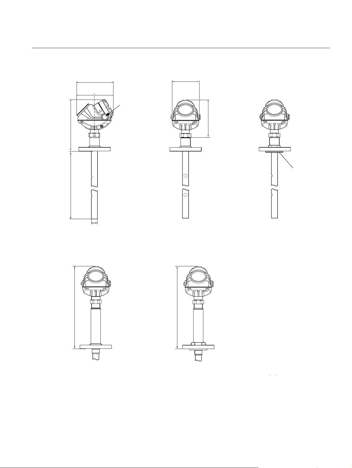
Product Data Sheet
L 20 feet (6 m)
10.1 (257.1)
5.2 (133)7.1 (180)
3.4 (87) 3.6 (92)
1.1 (28)
7.4 (188.5)
½ - 14 NPT
Optional
adapters:
M20x1.5,
eurofast and
minifast
The Alloy
probes are
designed with
a protective
plate.
HTHP/HP/C version
15.6 (397.5)
15.6 (397.5)
HTHP/HP Plate Design
(Option for Alloy versions)
00813-0100-4530, Rev DA
December 2010
Rosemount 5300 Series
COAXIAL PROBE WITH FLANGE CONNECTION
Dimensions are in inches
(millimeters)
45

Rosemount 5300 Series
L 20 feet (6 m)
NPT 1/1½/2 inch NPT 1/1½/2 inch
5.2 (133)
7.4 (188.5)
2.4 (62)
7.1 (180)
1 in., 1½ in.: s52
2 in.: s60
3.6 (92)3.4 (87)
1.1 (28)
10.1 (257.1)
½ - 14 NPT
Optional
adapters:
M20x1.5,
eurofast and
minifast
1.1 (28)
G 1/1½ inch
3.4 (87)
1.1 (27)
7.1 (180)
3.6 (92)
10.1 (257.1)
NPT: s50
G: s60
15.6 (397.5)
HTHP/HP/C version
L
20 feet (6 m)
NPT 1½, G 1½ inch
1 in.: s52
1½ in.: s60
Product Data Sheet
00813-0100-4530, Rev DA
December 2010
COAXIAL PROBE WITH THREADED CONNECTION
Dimensions are in inches
(millimeters)
46

Product Data Sheet
1.0 (26)
s60
5.2 (133)
7.4 (188.5)
1.8 (45)
7.1 (180)
L
10 feet
(3 m)
3.4 (87)
Ø 0.24 (6)
Ø 0.31 (8)
½ - 14 NPT
Optional
adapters:
M20x1.5,
eurofast and
minifast
G 1½ inch
NPT 1½ / 2 inch NPT 1½ / 2 inch
1½ in.: s52
2 in.: s60
1.1 (27)
7.1 (180)
3.6 (92) 3.6 (92)3.4 (87)
10.2 (259.5)
1.0 (26)
Ø 0.31 (8)
Ø 0.24 (6)
L
10 feet
(3 m)
10.2 (259.5)
Ø 0.24 (6)
Ø 0.31 (8)
Flange
3.4 (87) 3.6 (92)
7.1 (180)
5.2 (133)
7.4 (188.5)
1.0 (26)
L
10 feet
(3 m)
10.2 (259.5)
00813-0100-4530, Rev DA
December 2010
Rosemount 5300 Series
RIGID TWIN LEAD PROBE
Dimensions are in inches
(millimeters)
47

Rosemount 5300 Series
1.4 (35)
s60
3.5 (90)
3.5 (90)
Ø 0.16 (4)
Ø 0.16 (4)
1.4 (35)
5.2 (133)
7.4 (188.5)
1.8 (45)
L
164 feet
(50 m)
7.1 (180)
3.4 (87)
Ø 0.16 (4)
Ø 0.16 (4)
G 1½ inch
NPT 1½ / 2 inch
NPT 1½ / 2 inch
1½ in.: s52
2 in.: s60
1.1 (27)
7.1 (180)
3.6 (92) 3.6 (92)3.4 (87)
L
164 feet
(50 m)
10.2 (259.5) 10.2 (259.5)
½ - 14 NPT
Optional
adapters:
M20x1.5,
eurofast and
minifast
3.5 (90)
1.4 (35)
Ø 0.16 (4)
Ø 0.16 (4)
Flange
3.4 (87) 3.6 (92)
7.1 (180)
5.2 (133)
7.4 (188.5)
L
164 feet
(50 m)
10.2 (259.5)
Product Data Sheet
00813-0100-4530, Rev DA
December 2010
FLEXIBLE TWIN LEAD PROBE
Dimensions are in inches
(millimeters)
48

Product Data Sheet
Pipe diameter
max 2.5 in. (64 mm)
5.2 (133)
Pipe mounting
(vertical pipe)
Wall mounting
Pipe mounting
(horizontal pipe)
2.2 (57)
0.3 (7)
0.8 (20)
2.8 (70)
Hole pattern
wall mounting
00813-0100-4530, Rev DA
December 2010
Rosemount 5300 Series
BRACKET MOUNTING
Dimensions are in inches
(millimeters)
49

Rosemount 5300 Series
5.2 (133)
7.4 (188.5)
5.2 (133)
7 (180)
3.4
(87)
3.6
(92)
R
min
1.4 (35)
H
min
:
6.9 (175) Standard Variant
12.4 (315) HTHP/HP/C Variant
3, 6, 9 ft. (1, 2, or 3 m)
Product Data Sheet
00813-0100-4530, Rev DA
December 2010
REMOTE HOUSING
Dimensions are in inches
(millimeters)
50

Product Data Sheet
NOTE
Dimensions may be used to aid in the identification of installed flanges. It is not intended for manufacturing use.
D
B
1
G
Raised Face Recessed Face
KG
B
1
DK
B
2
B
2
D: Outside diameter
B1: Flange thickness with
gasket surface
B2: Flange thickness without
gasket surface
F=B
1-B2
: Gasket surface
thickness
G: Gasket surface diameter
# Bolts: Number of Bolts
K: Bolt hole circle diameter
D
i
D
o
Flushing Connection Ring
D
H
Height: 0.97 in.
(24.6 mm)
00813-0100-4530, Rev DA
December 2010
Rosemount 5300 Series
SPECIAL FLANGES AND FLUSHING CONNECTION RINGS
Special Flanges
Fisher 249B/259B
Fisher 249C
Masoneilan
(1) These flanges are also available in a vented version.
(2) Flange with raised face.
(3) Flange with recessed face.
(1)
(3)
(2)
D B
(2)
9.00 (228.6) 1.50 (38.2) 1.25 (31.8) 0.25 (6.4) 5.23 (132.8) 8 7.25 (184.2)
5.69 (144.5) 0.94 (23.8) 1.13 (28.6) -0.19 (-4.8) 3.37 (85.7) 8 4.75 (120.65)
7.51 (191.0) 1.54 (39.0) 1.30 (33.0) 0.24 (6.0) 4.02 (102.0) 8 5.87 (149.0)
1
B
2
F G # Bolts K
Dimensions are in inches
(millimeters)
Masoneilan and Fisher flanges are also available in
vented versions (see “Vented Flanges” on page 15),
with the same dimensions as shown in the table
above.
Flushing Connection
Rings
2 in. ANSI 2.12 (53.8) 3.62 (91.9) ¼ in. NPT
3 in. ANSI 3.60 (91.4) 5.00 (127.0) ¼ in. NPT
4 in. ANSI 3.60 (91.4) 6.20 (157.5) ¼ in. NPT
DN50 2.40 (61.0) 4.00 (102.0) ¼ in. NPT
DN80 3.60 (91.4) 5.43 (138.0) ¼ in. NPT
Pressure and temperature rating for flushing ring up
to Class 2500.
Vented flanges must be ordered with a 1 ½ in. NPT
threaded process connection (code RA).
For information about flange temperature and
pressure ratings, see page 22.
D
i
D
o
D
H
51

Product Data Sheet
00813-0100-4530, Rev DA
December 2010
Emerson provides a complete range of Rosemount products for level measurement applications.
Rosemount 5300 Series
Rosemount Level Solutions
Vibrating Fork Switches – Point Level Detection
For high and low alarms, overfill protection, pump control,
including wide pressure and temperature requirements, and
hygienic applications. Flexible mounting. Immune to changing
process conditions and suitable for most liquids.
The product line consists of:
• Rosemount 2160 Wireless
• Rosemount 2130 Enhanced
• Rosemount 2120 Full-featured
• Rosemount 2110 Compact
Differential Pressure – Level or Interface Measurement
Flexible mounting for liquid tank levels, including those with wide
temperature and pressure requirements. Can be isolated by
valves. Unaffected by: vapor space changes, surface conditions,
foam, corrosive fluids, internal tank equipment. Optimize
performance with direct mount, Tuned-System Assemblies:
• Rosemount DP Level Transmitters and Remote Seals
• Rosemount 3051S_L, 3051L, and 2051L Liquid Level
Transmitters
Ultrasonic – Level Measurement
Top mounted, non-contacting for simple tank and open air level
measurements. Unaffected by fluid properties such as: density,
viscosity, dirty coating, and corrosiveness. Appropriate for
routine applications outside of explosion proof areas.
The product line consists of:
• Rosemount 3100 Series Ultrasonic Process Level
Transmitters
Guided Wave Radar – Level and Interface Measurement
Top mounted, direct level and interface measurement of liquids or
solids, including those with wide temperature and pressure
requirements. Unaffected by changing process conditions. Good
fit for small spaces and easy swap for older technologies.
The product line consists of:
• Rosemount 5300 Series – Accurate, superior performance
transmitter in most applications including process vessels and
control
• Rosemount 3300 Series – Versatile and easy-to-use transmitter
in most liquid storage and monitoring applications
Non-contacting Radar – Level Measurement
Top mounted, direct level measurement for liquids or solids,
including those with wide temperature and pressure requirements.
Can be isolated by valves. Unaffected by changing process
conditions. Good for dirty, coating, and corrosive applications.
The product line consists of:
• Rosemount 5400 Series – Accurate, superior performance
2-wire transmitters for most liquid level applications and
process conditions
• Rosemount 5600 Series – 4-wire transmitters with maximum
sensitivity and performance for solids, challenging reactors,
rapid level changes and excessive process conditions
Chambers for Process Level Instrumentation
• Rosemount 9901 – High quality chambers for external
mounting of level measurement and control instrumentation on
process vessels
Standard Terms and Conditions of Sale can be found at www.rosemount.com\terms_of_sale
The Emerson logo is a trademark and service mark of Emerson Electric Co.
Rosemount and the Rosemount logotype are registered trademarks of Rosemount Inc.
Fisher is a mark owned by Fisher Controls International LLC, a member of the Emerson Process Management business division of Emerson
Electric Co.
PlantWeb is a registered trademark of the Emerson Process Management group of companies.
HART and WirelessHART are registered trademarks of the HART Communication Foundation.
Viton, and Kalrez are registered trademarks of Du Pont Performance Elastomers.
OUNDATION is a trademark of the Fieldbus Foundation.
F
DeltaV is a trademark of Emerson Process Management group of companies.
Eurofast and Minifast are registered trademarks of Turck Inc.
Masoneilan is a registered trademark of Dresser Inc.
All other marks are the property of their respective owners.
© 2010 Rosemount Inc. All rights reserved.
Emerson Process Management
Rosemount Measurement
8200 Market Boulevard
Chanhassen MN 55317 USA
Tel (USA) 1 800 999 9307
Tel (International) +1 952 906 8888
Fax +1 952 949 7001
Emerson Process Management
Blegistrasse 23
P.O. Box 1046
CH 6341 Baar
Switzerland
Tel +41 (0) 41 768 6111
Fax +41 (0) 41 768 6300
Emerson FZE
P.O.Box 17033
Jebeli Ali Free Zone
Dubai UAE
Tel +971 4 811 8100
Fax +971 4 886 5465
Emerson Process Management Asia
Pacific Pte Ltd
1 Pandan Crescent
Singapore 128461
Tel +65 6777 8211
Fax +65 6777 0947
Service Support Hotline: +65 6770 8711
Email: Enquiries@AP.EmersonProcess.com
00813-0100-4530 Rev DA, 12/10
A.P.O. - ELMOS v.o.s., Pražská 90, 509 01 Nová Paka, Tel.: +420 493 504 261, Fax: +420 493 504 257, E-mail: apo@apoelmos.cz, Internet: www.apoelmos.cz
 Loading...