

Page 1
Reference Manual
00809-0100-4530, Rev BA
July 2009
Rosemount 5300 Series
Superior Performance Guided Wave Radar
www.rosemount.com
Page 2

Page 3

Reference Manual
NOTICE
00809-0100-4530, Rev BA
July 2009
Rosemount 5300 Series
Rosemount 5300 Series
Guided Wave Radar Level and
Interface Transmitters
Read this manual before working with the product. For personal and system safety, and for
optimum product performance, make sure you thoroughly understand the contents before
installing, using, or maintaining this product.
Within the United States, Emerson Process Management has two toll-free assistance
numbers.
Customer Central: 1-800-999-9307(7:00 a.m. to 7:00 p.m. CST)
Technical support, quoting, and order-related questions.
North American Response Center:
Equipment service needs.
1-800-654-7768 (24 hours a day – Includes Canada)
For equipment service or support needs outside the United States, contact your local
Emerson Process Management representative.
The products described in this document are NOT designed for nuclear-qualified
applications.
Using non-nuclear qualified products in applications that require nuclear-qualified hardware
or products may cause inaccurate readings.
For information on Rosemount nuclear-qualified products, contact your local Emerson
Process Management Sales Representative.
This product is designed to meet FCC and R&TTE requirements for a non-intentional
radiator. It does not require any licensing whatsoever and has no tank restrictions
associated with telecommunications issues.
This device complies with part 15 of the FCC rules. Operation is subject to the following two
conditions: (1) This device may not cause harmful interference, and (2) this device must
accept any interference received, including interference that may cause undesired
operation.
Cover Photo: 5300_coverphoto.tif
www.rosemount.com
Page 4

Page 5

Reference Manual
00809-0100-4530, Rev BA
July 2009
Rosemount 5300 Series
Table of Contents
SECTION 1
Introduction
SECTION 2
Transmitter Overview
Safety Messages. . . . . . . . . . . . . . . . . . . . . . . . . . . . . . . . . . . . . . . . . 1-1
Manual Overview. . . . . . . . . . . . . . . . . . . . . . . . . . . . . . . . . . . . . . . . . 1-2
Service Support. . . . . . . . . . . . . . . . . . . . . . . . . . . . . . . . . . . . . . . . . . 1-3
Product Recycling/Disposal. . . . . . . . . . . . . . . . . . . . . . . . . . . . . . . . . 1-4
Theory of Operation. . . . . . . . . . . . . . . . . . . . . . . . . . . . . . . . . . . . . . . 2-1
Applications . . . . . . . . . . . . . . . . . . . . . . . . . . . . . . . . . . . . . . . . . . . . . 2-2
Components of the Transmitter . . . . . . . . . . . . . . . . . . . . . . . . . . . . . . 2-5
System Architecture. . . . . . . . . . . . . . . . . . . . . . . . . . . . . . . . . . . . . . . 2-7
Probe Selection Guide. . . . . . . . . . . . . . . . . . . . . . . . . . . . . . . . . . . . . 2-9
Transition Zones. . . . . . . . . . . . . . . . . . . . . . . . . . . . . . . . . . . . . . 2-10
Process Characteristics. . . . . . . . . . . . . . . . . . . . . . . . . . . . . . . . . . . 2-11
Coating. . . . . . . . . . . . . . . . . . . . . . . . . . . . . . . . . . . . . . . . . . . . . 2-11
Bridging . . . . . . . . . . . . . . . . . . . . . . . . . . . . . . . . . . . . . . . . . . . . 2-11
Foam . . . . . . . . . . . . . . . . . . . . . . . . . . . . . . . . . . . . . . . . . . . . . . 2-11
Vapor . . . . . . . . . . . . . . . . . . . . . . . . . . . . . . . . . . . . . . . . . . . . . . 2-11
Boiling Hydrocarbons . . . . . . . . . . . . . . . . . . . . . . . . . . . . . . . . . . 2-11
Measuring Range. . . . . . . . . . . . . . . . . . . . . . . . . . . . . . . . . . . . . 2-12
Interface . . . . . . . . . . . . . . . . . . . . . . . . . . . . . . . . . . . . . . . . . . . . 2-12
Vessel Characteristics. . . . . . . . . . . . . . . . . . . . . . . . . . . . . . . . . . . . 2-14
Heating Coils, Agitators . . . . . . . . . . . . . . . . . . . . . . . . . . . . . . . . 2-14
Tank Shape . . . . . . . . . . . . . . . . . . . . . . . . . . . . . . . . . . . . . . . . . 2-14
Installation Procedure . . . . . . . . . . . . . . . . . . . . . . . . . . . . . . . . . . . . 2-15
SECTION 3
Mechanical Installation
Safety messages. . . . . . . . . . . . . . . . . . . . . . . . . . . . . . . . . . . . . . . . . 3-1
Mounting Considerations. . . . . . . . . . . . . . . . . . . . . . . . . . . . . . . . . . . 3-3
Process Connection . . . . . . . . . . . . . . . . . . . . . . . . . . . . . . . . . . . . 3-3
Installation of Single Lead Probes in Non-metallic Vessels . . . . . . 3-5
Installation in Concrete Silos . . . . . . . . . . . . . . . . . . . . . . . . . . . . . 3-6
Considerations for Solid Applications. . . . . . . . . . . . . . . . . . . . . . . 3-6
Mounting in Chamber/ Still Pipe. . . . . . . . . . . . . . . . . . . . . . . . . . . 3-7
Replacing a Displacer in an Existing Displacer Chamber . . . . . . 3-10
Free Space. . . . . . . . . . . . . . . . . . . . . . . . . . . . . . . . . . . . . . . . . . 3-11
Recommended Mounting Position for Liquids . . . . . . . . . . . . . . . 3-12
Recommended Mounting for Solids . . . . . . . . . . . . . . . . . . . . . . . 3-13
Insulated Tanks . . . . . . . . . . . . . . . . . . . . . . . . . . . . . . . . . . . . . . 3-14
Mounting . . . . . . . . . . . . . . . . . . . . . . . . . . . . . . . . . . . . . . . . . . . . . . 3-15
Flange Connection . . . . . . . . . . . . . . . . . . . . . . . . . . . . . . . . . . . . 3-15
Threaded Connection. . . . . . . . . . . . . . . . . . . . . . . . . . . . . . . . . . 3-16
Tri-Clamp Connection. . . . . . . . . . . . . . . . . . . . . . . . . . . . . . . . . . 3-17
Bracket Mounting . . . . . . . . . . . . . . . . . . . . . . . . . . . . . . . . . . . . . 3-18
Shortening the Probe . . . . . . . . . . . . . . . . . . . . . . . . . . . . . . . . . . 3-19
Anchoring . . . . . . . . . . . . . . . . . . . . . . . . . . . . . . . . . . . . . . . . . . . 3-22
Mounting a Centering Disc for Pipe Installations . . . . . . . . . . . . . 3-25
www.rosemount.com
Page 6

Rosemount 5300 Series
Reference Manual
00809-0100-4530, Rev BA
July 2009
SECTION 4
Electrical Installation
SECTION 5
Configuration
Safety messages. . . . . . . . . . . . . . . . . . . . . . . . . . . . . . . . . . . . . . . . . 4-1
Cable/conduit entries. . . . . . . . . . . . . . . . . . . . . . . . . . . . . . . . . . . . . . 4-3
Grounding . . . . . . . . . . . . . . . . . . . . . . . . . . . . . . . . . . . . . . . . . . . . . . 4-3
Cable Selection . . . . . . . . . . . . . . . . . . . . . . . . . . . . . . . . . . . . . . . . . . 4-3
Hazardous Areas. . . . . . . . . . . . . . . . . . . . . . . . . . . . . . . . . . . . . . . . . 4-3
HART. . . . . . . . . . . . . . . . . . . . . . . . . . . . . . . . . . . . . . . . . . . . . . . . . . 4-4
Power Requirements . . . . . . . . . . . . . . . . . . . . . . . . . . . . . . . . . . . 4-4
Maximum Loop Resistance . . . . . . . . . . . . . . . . . . . . . . . . . . . . . . 4-4
Connecting the Transmitter . . . . . . . . . . . . . . . . . . . . . . . . . . . . . . 4-5
Non-Intrinsically Safe Output . . . . . . . . . . . . . . . . . . . . . . . . . . . . . 4-6
Intrinsically Safe Output . . . . . . . . . . . . . . . . . . . . . . . . . . . . . . . . . 4-7
OUNDATION Fieldbus. . . . . . . . . . . . . . . . . . . . . . . . . . . . . . . . . . . . . . 4-8
F
Power Requirements . . . . . . . . . . . . . . . . . . . . . . . . . . . . . . . . . . . 4-8
Connecting the Transmitter . . . . . . . . . . . . . . . . . . . . . . . . . . . . . . 4-8
Non-Intrinsically Safe Output . . . . . . . . . . . . . . . . . . . . . . . . . . . . 4-11
Intrinsically Safe Output . . . . . . . . . . . . . . . . . . . . . . . . . . . . . . . . 4-12
Optional Devices . . . . . . . . . . . . . . . . . . . . . . . . . . . . . . . . . . . . . . . . 4-13
Tri-Loop HART to analog converter . . . . . . . . . . . . . . . . . . . . . . . 4-13
751 Field Signal Indicator. . . . . . . . . . . . . . . . . . . . . . . . . . . . . . . 4-14
Safety messages. . . . . . . . . . . . . . . . . . . . . . . . . . . . . . . . . . . . . . . . . 5-1
Overview . . . . . . . . . . . . . . . . . . . . . . . . . . . . . . . . . . . . . . . . . . . . . . . 5-2
Basic Configuration . . . . . . . . . . . . . . . . . . . . . . . . . . . . . . . . . . . . 5-2
Echo Tuning . . . . . . . . . . . . . . . . . . . . . . . . . . . . . . . . . . . . . . . . . . 5-2
LCD Configuration . . . . . . . . . . . . . . . . . . . . . . . . . . . . . . . . . . . . . 5-2
Advanced Configuration. . . . . . . . . . . . . . . . . . . . . . . . . . . . . . . . . 5-2
Configuration Tools . . . . . . . . . . . . . . . . . . . . . . . . . . . . . . . . . . . . 5-2
Basic Configuration Parameters . . . . . . . . . . . . . . . . . . . . . . . . . . . . . 5-4
Measurement Units . . . . . . . . . . . . . . . . . . . . . . . . . . . . . . . . . . . . 5-4
Tank and Probe Geometry . . . . . . . . . . . . . . . . . . . . . . . . . . . . . . . 5-4
Tank Environment . . . . . . . . . . . . . . . . . . . . . . . . . . . . . . . . . . . . . 5-6
Volume Configuration. . . . . . . . . . . . . . . . . . . . . . . . . . . . . . . . . . . 5-7
Analog Output (HART) . . . . . . . . . . . . . . . . . . . . . . . . . . . . . . . . . . 5-9
Basic Configuration Using a 375 Field Communicator . . . . . . . . . . . 5-11
Basic Configuration Using Rosemount Radar Master . . . . . . . . . . . . 5-13
System Requirements . . . . . . . . . . . . . . . . . . . . . . . . . . . . . . . . . 5-13
Help In RRM. . . . . . . . . . . . . . . . . . . . . . . . . . . . . . . . . . . . . . . . . 5-13
Installing the RRM software for HART communication . . . . . . . . 5-14
Specifying the COM Port . . . . . . . . . . . . . . . . . . . . . . . . . . . . . . . 5-15
To set the COM port buffers. . . . . . . . . . . . . . . . . . . . . . . . . . . . . 5-15
Installing the RRM Software for FOUNDATION Fieldbus . . . . . . 5-16
Specifying Measurement Units. . . . . . . . . . . . . . . . . . . . . . . . . . . 5-17
Using the Setup Functions . . . . . . . . . . . . . . . . . . . . . . . . . . . . . . 5-18
Guided Setup . . . . . . . . . . . . . . . . . . . . . . . . . . . . . . . . . . . . . . . . 5-19
Device Properties. . . . . . . . . . . . . . . . . . . . . . . . . . . . . . . . . . . . . 5-20
General Information . . . . . . . . . . . . . . . . . . . . . . . . . . . . . . . . . . . 5-20
Probe . . . . . . . . . . . . . . . . . . . . . . . . . . . . . . . . . . . . . . . . . . . . . . 5-21
Geometry . . . . . . . . . . . . . . . . . . . . . . . . . . . . . . . . . . . . . . . . . . . 5-22
Tank Environment . . . . . . . . . . . . . . . . . . . . . . . . . . . . . . . . . . . . 5-23
Volume . . . . . . . . . . . . . . . . . . . . . . . . . . . . . . . . . . . . . . . . . . . . . 5-25
Analog Output (HART) . . . . . . . . . . . . . . . . . . . . . . . . . . . . . . . . . 5-26
Finish Configuration Wizard . . . . . . . . . . . . . . . . . . . . . . . . . . . . . 5-26
TOC-2
Page 7

Reference Manual
00809-0100-4530, Rev BA
July 2009
Rosemount 5300 Series
Device Specific Configuration. . . . . . . . . . . . . . . . . . . . . . . . . . . . 5-27
Restart the Transmitter. . . . . . . . . . . . . . . . . . . . . . . . . . . . . . . . . 5-28
View Measured Values. . . . . . . . . . . . . . . . . . . . . . . . . . . . . . . . . 5-28
Backup . . . . . . . . . . . . . . . . . . . . . . . . . . . . . . . . . . . . . . . . . . . . . 5-28
Basic Configuration Using AMS Suite (HART) . . . . . . . . . . . . . . . . . 5-30
Basic Configuration Using DeltaV . . . . . . . . . . . . . . . . . . . . . . . . . . . 5-31
OUNDATION Fieldbus Overview. . . . . . . . . . . . . . . . . . . . . . . . . . . . . 5-36
F
Assigning Device Tag and Node Address . . . . . . . . . . . . . . . . . . 5-36
Foundation Fieldbus Block Operation . . . . . . . . . . . . . . . . . . . . . 5-37
Configure the AI Block. . . . . . . . . . . . . . . . . . . . . . . . . . . . . . . . . . . . 5-39
Application Example 1 . . . . . . . . . . . . . . . . . . . . . . . . . . . . . . . . . 5-42
Application Example 2 . . . . . . . . . . . . . . . . . . . . . . . . . . . . . . . . . 5-43
Application Example 3 . . . . . . . . . . . . . . . . . . . . . . . . . . . . . . . . . 5-44
Tri-Loop HART to Analog Converter . . . . . . . . . . . . . . . . . . . . . . . . . 5-45
HART Multi-drop Configuration . . . . . . . . . . . . . . . . . . . . . . . . . . . . . 5-47
SECTION 6
Operation
SECTION 7
Service and
Troubleshooting
Safety Messages. . . . . . . . . . . . . . . . . . . . . . . . . . . . . . . . . . . . . . . . . 6-1
Viewing Measurement Data. . . . . . . . . . . . . . . . . . . . . . . . . . . . . . . . . 6-2
Using the Display Panel . . . . . . . . . . . . . . . . . . . . . . . . . . . . . . . . . 6-2
Specifying Display Panel Variables . . . . . . . . . . . . . . . . . . . . . . . . 6-3
Viewing Measurement Data in RRM . . . . . . . . . . . . . . . . . . . . . . . 6-7
Viewing Measurement Data in AMS Suite . . . . . . . . . . . . . . . . . . . 6-8
Viewing Measurement Data in DeltaV . . . . . . . . . . . . . . . . . . . . . . 6-9
Safety messages. . . . . . . . . . . . . . . . . . . . . . . . . . . . . . . . . . . . . . . . . 7-1
Analyzing the Measurement Signal. . . . . . . . . . . . . . . . . . . . . . . . . . . 7-3
Surface Pulse Not Found. . . . . . . . . . . . . . . . . . . . . . . . . . . . . . . . . . . 7-5
Probe End Projection . . . . . . . . . . . . . . . . . . . . . . . . . . . . . . . . . . . 7-6
Disturbance Echo Handling. . . . . . . . . . . . . . . . . . . . . . . . . . . . . . . . . 7-7
Amplitude Threshold Curve . . . . . . . . . . . . . . . . . . . . . . . . . . . . . . 7-7
Disturbances at the Top of the Tank . . . . . . . . . . . . . . . . . . . . . . . 7-7
Interface Pulse not Found . . . . . . . . . . . . . . . . . . . . . . . . . . . . . . . . . . 7-8
Signal Quality Metrics. . . . . . . . . . . . . . . . . . . . . . . . . . . . . . . . . . . 7-9
Using the Echo Curve Analyzer. . . . . . . . . . . . . . . . . . . . . . . . . . . . . 7-10
Using the Rosemount Radar Master . . . . . . . . . . . . . . . . . . . . . . 7-10
The Configuration Mode Tab . . . . . . . . . . . . . . . . . . . . . . . . . . . . 7-11
The View/Record ModeTab . . . . . . . . . . . . . . . . . . . . . . . . . . . . . 7-12
The File ModeTab . . . . . . . . . . . . . . . . . . . . . . . . . . . . . . . . . . . . 7-13
Using the Echo Curve Analyzer with a 375 Field Communicator. 7-13
Interface Measurements with Fully Submerged Probes . . . . . . . . . . 7-15
Analog Output Calibration . . . . . . . . . . . . . . . . . . . . . . . . . . . . . . . . . 7-16
Level and Distance Calibration . . . . . . . . . . . . . . . . . . . . . . . . . . . . . 7-17
Logging Measurement Data . . . . . . . . . . . . . . . . . . . . . . . . . . . . . . . 7-19
Backing up the Transmitter Configuration . . . . . . . . . . . . . . . . . . . . . 7-20
Configuration Report . . . . . . . . . . . . . . . . . . . . . . . . . . . . . . . . . . . . . 7-21
Reset to Factory Settings . . . . . . . . . . . . . . . . . . . . . . . . . . . . . . . . . 7-22
Diagnostics . . . . . . . . . . . . . . . . . . . . . . . . . . . . . . . . . . . . . . . . . . . . 7-23
Using the Simulation Mode . . . . . . . . . . . . . . . . . . . . . . . . . . . . . . . . 7-25
Write Protecting a Transmitter. . . . . . . . . . . . . . . . . . . . . . . . . . . . . . 7-26
Enter Service Mode in RRM . . . . . . . . . . . . . . . . . . . . . . . . . . . . . . . 7-26
Viewing Input and Holding Registers. . . . . . . . . . . . . . . . . . . . . . . . . 7-27
Removing the Transmitter Head . . . . . . . . . . . . . . . . . . . . . . . . . . . . 7-28
TOC-3
Page 8

Rosemount 5300 Series
Changing a Probe . . . . . . . . . . . . . . . . . . . . . . . . . . . . . . . . . . . . . . . 7-29
Probe and Firmware Compatibility . . . . . . . . . . . . . . . . . . . . . . . . 7-29
Check Firmware and Probe Version. . . . . . . . . . . . . . . . . . . . . . . 7-30
Changing the Probe . . . . . . . . . . . . . . . . . . . . . . . . . . . . . . . . . . . 7-31
Diagnostic Messages. . . . . . . . . . . . . . . . . . . . . . . . . . . . . . . . . . . . . 7-33
Troubleshooting . . . . . . . . . . . . . . . . . . . . . . . . . . . . . . . . . . . . . . 7-33
Device Status . . . . . . . . . . . . . . . . . . . . . . . . . . . . . . . . . . . . . . . . 7-35
Errors . . . . . . . . . . . . . . . . . . . . . . . . . . . . . . . . . . . . . . . . . . . . . . 7-36
Warnings . . . . . . . . . . . . . . . . . . . . . . . . . . . . . . . . . . . . . . . . . . . 7-37
Measurement Status . . . . . . . . . . . . . . . . . . . . . . . . . . . . . . . . . . 7-38
Interface Status . . . . . . . . . . . . . . . . . . . . . . . . . . . . . . . . . . . . . . 7-40
Volume Calculation Status . . . . . . . . . . . . . . . . . . . . . . . . . . . . . . 7-40
Analog Output Status . . . . . . . . . . . . . . . . . . . . . . . . . . . . . . . . . . 7-41
LCD Error Messages. . . . . . . . . . . . . . . . . . . . . . . . . . . . . . . . . . . . . 7-42
LED Error Messages . . . . . . . . . . . . . . . . . . . . . . . . . . . . . . . . . . . . . 7-43
Foundation Fieldbus Error Messages . . . . . . . . . . . . . . . . . . . . . . . . 7-44
Resource Block . . . . . . . . . . . . . . . . . . . . . . . . . . . . . . . . . . . . . . 7-44
Transducer Block . . . . . . . . . . . . . . . . . . . . . . . . . . . . . . . . . . . . . 7-45
Analog Input (AI) Function Block . . . . . . . . . . . . . . . . . . . . . . . . . 7-45
Reference Manual
00809-0100-4530, Rev BA
July 2009
SECTION 8
Safety Instrumented
Systems (4-20 mA only)
APPENDIX A
Reference Data
Safety Messages. . . . . . . . . . . . . . . . . . . . . . . . . . . . . . . . . . . . . . . . . 8-1
Overview . . . . . . . . . . . . . . . . . . . . . . . . . . . . . . . . . . . . . . . . . . . . . . . 8-3
Applicable Models . . . . . . . . . . . . . . . . . . . . . . . . . . . . . . . . . . . . . 8-3
Skill Level of Personnel . . . . . . . . . . . . . . . . . . . . . . . . . . . . . . . . . 8-3
Functional Specifications. . . . . . . . . . . . . . . . . . . . . . . . . . . . . . . . . . . 8-4
Installation . . . . . . . . . . . . . . . . . . . . . . . . . . . . . . . . . . . . . . . . . . . . . . 8-4
Configuration . . . . . . . . . . . . . . . . . . . . . . . . . . . . . . . . . . . . . . . . . . . . 8-4
Damping. . . . . . . . . . . . . . . . . . . . . . . . . . . . . . . . . . . . . . . . . . . . . 8-4
Alarm and Saturation Levels . . . . . . . . . . . . . . . . . . . . . . . . . . . . . 8-5
Write Protection . . . . . . . . . . . . . . . . . . . . . . . . . . . . . . . . . . . . . . . 8-5
Site Acceptance . . . . . . . . . . . . . . . . . . . . . . . . . . . . . . . . . . . . . . . 8-5
Operation and Maintenance . . . . . . . . . . . . . . . . . . . . . . . . . . . . . . . . 8-5
General. . . . . . . . . . . . . . . . . . . . . . . . . . . . . . . . . . . . . . . . . . . . . . 8-5
Inspection. . . . . . . . . . . . . . . . . . . . . . . . . . . . . . . . . . . . . . . . . . . . 8-7
References . . . . . . . . . . . . . . . . . . . . . . . . . . . . . . . . . . . . . . . . . . . . . 8-7
Specifications . . . . . . . . . . . . . . . . . . . . . . . . . . . . . . . . . . . . . . . . . 8-7
Failure Rate Data . . . . . . . . . . . . . . . . . . . . . . . . . . . . . . . . . . . . . . 8-7
Useful Lifetime . . . . . . . . . . . . . . . . . . . . . . . . . . . . . . . . . . . . . . . . 8-7
Spare Parts . . . . . . . . . . . . . . . . . . . . . . . . . . . . . . . . . . . . . . . . . . . . . 8-7
Terms and Definitions . . . . . . . . . . . . . . . . . . . . . . . . . . . . . . . . . . . . . 8-7
Specifications. . . . . . . . . . . . . . . . . . . . . . . . . . . . . . . . . . . . . . . . . . . .A-1
Process Temperature and Pressure Rating . . . . . . . . . . . . . . . . . .A-4
Flange Connection Rating . . . . . . . . . . . . . . . . . . . . . . . . . . . . . . .A-6
Flange Rating Standards . . . . . . . . . . . . . . . . . . . . . . . . . . . . . . . .A-6
Ambient Temperature. . . . . . . . . . . . . . . . . . . . . . . . . . . . . . . . . . .A-7
Remote Housing Measuring Range . . . . . . . . . . . . . . . . . . . . . . . .A-8
Dimensional Drawings. . . . . . . . . . . . . . . . . . . . . . . . . . . . . . . . . . . . .A-9
Ordering Information . . . . . . . . . . . . . . . . . . . . . . . . . . . . . . . . . . . . .A-21
Spare Parts . . . . . . . . . . . . . . . . . . . . . . . . . . . . . . . . . . . . . . . . . . . .A-30
TOC-4
Page 9

Reference Manual
00809-0100-4530, Rev BA
July 2009
Rosemount 5300 Series
APPENDIX B
Product Certifications
APPENDIX C
Advanced Configuration
Safety messages. . . . . . . . . . . . . . . . . . . . . . . . . . . . . . . . . . . . . . . . .B-1
EU Conformity . . . . . . . . . . . . . . . . . . . . . . . . . . . . . . . . . . . . . . . . . . .B-2
European ATEX Directive Information. . . . . . . . . . . . . . . . . . . . . . . . .B-3
Intrinsic Safety . . . . . . . . . . . . . . . . . . . . . . . . . . . . . . . . . . . . . . . .B-3
Flameproof . . . . . . . . . . . . . . . . . . . . . . . . . . . . . . . . . . . . . . . . . . .B-6
National Supervision and Inspection Center for Explosion Protection
and Safety of Instrumentation (NEPSI) Approvals. . . . . . . . . . . . . . . .B-8
Factory Mutual (FM) Approvals . . . . . . . . . . . . . . . . . . . . . . . . . . . . .B-11
Intrinsic Safety . . . . . . . . . . . . . . . . . . . . . . . . . . . . . . . . . . . . . . .B-11
Explosion Proof . . . . . . . . . . . . . . . . . . . . . . . . . . . . . . . . . . . . . .B-13
Canadian Standards Association (CSA) Approval. . . . . . . . . . . . . . .B-14
Intrinsic Safety . . . . . . . . . . . . . . . . . . . . . . . . . . . . . . . . . . . . . . .B-14
Explosion Proof . . . . . . . . . . . . . . . . . . . . . . . . . . . . . . . . . . . . . .B-16
IECEx Approval . . . . . . . . . . . . . . . . . . . . . . . . . . . . . . . . . . . . . . . . .B-17
Intrinsic Safety . . . . . . . . . . . . . . . . . . . . . . . . . . . . . . . . . . . . . . .B-17
Flameproof . . . . . . . . . . . . . . . . . . . . . . . . . . . . . . . . . . . . . . . . . .B-20
Combination Approvals . . . . . . . . . . . . . . . . . . . . . . . . . . . . . . . . . . .B-22
Approval Drawings. . . . . . . . . . . . . . . . . . . . . . . . . . . . . . . . . . . . . . .B-22
Safety messages. . . . . . . . . . . . . . . . . . . . . . . . . . . . . . . . . . . . . . . . .C-1
User Defined Upper Reference Point . . . . . . . . . . . . . . . . . . . . . . . . .C-3
Handling of Disturbances from Nozzle . . . . . . . . . . . . . . . . . . . . . . . .C-4
Trim Near Zone . . . . . . . . . . . . . . . . . . . . . . . . . . . . . . . . . . . . . . .C-4
Changing the Upper Null Zone. . . . . . . . . . . . . . . . . . . . . . . . . . . .C-7
Threshold Settings. . . . . . . . . . . . . . . . . . . . . . . . . . . . . . . . . . . . . . . .C-8
Probe End Projection. . . . . . . . . . . . . . . . . . . . . . . . . . . . . . . . . . . . .C-10
Echo Tracking . . . . . . . . . . . . . . . . . . . . . . . . . . . . . . . . . . . . . . . . . .C-12
Dielectric Constant Settings. . . . . . . . . . . . . . . . . . . . . . . . . . . . . . . .C-14
Static Vapor Compensation . . . . . . . . . . . . . . . . . . . . . . . . . . . . .C-14
Lower Product . . . . . . . . . . . . . . . . . . . . . . . . . . . . . . . . . . . . . . .C-14
Dynamic Vapor Compensation . . . . . . . . . . . . . . . . . . . . . . . . . . . . .C-15
Installation Setup . . . . . . . . . . . . . . . . . . . . . . . . . . . . . . . . . . . . .C-18
Signal Quality Metrics . . . . . . . . . . . . . . . . . . . . . . . . . . . . . . . . . . . .C-20
Viewing Signal Quality Metrics in RRM . . . . . . . . . . . . . . . . . . . .C-21
APPENDIX D
Remote Mounting
APPENDIX E
Performing Proof Test
APPENDIX F
Level Transducer Block
Remote Housing, New Units . . . . . . . . . . . . . . . . . . . . . . . . . . . . . . . .D-1
Remote Connection, Field Retrofit. . . . . . . . . . . . . . . . . . . . . . . . . . . .D-3
Remote Housing Configuration . . . . . . . . . . . . . . . . . . . . . . . . . . . . . .D-4
Performing Proof Test . . . . . . . . . . . . . . . . . . . . . . . . . . . . . . . . . . . . .E-1
375 Field Communicator . . . . . . . . . . . . . . . . . . . . . . . . . . . . . . . . . . .E-1
Rosemount Radar Master (RRM) . . . . . . . . . . . . . . . . . . . . . . . . . . . .E-3
AMS Suite . . . . . . . . . . . . . . . . . . . . . . . . . . . . . . . . . . . . . . . . . . . . . .E-5
Overview . . . . . . . . . . . . . . . . . . . . . . . . . . . . . . . . . . . . . . . . . . . . . . . F-1
Definition. . . . . . . . . . . . . . . . . . . . . . . . . . . . . . . . . . . . . . . . . . . . . F-1
Channel Definitions . . . . . . . . . . . . . . . . . . . . . . . . . . . . . . . . . . . . F-2
Parameters and Descriptions . . . . . . . . . . . . . . . . . . . . . . . . . . . . . . . F-2
Supported Units. . . . . . . . . . . . . . . . . . . . . . . . . . . . . . . . . . . . . . . . . . F-8
Unit Codes . . . . . . . . . . . . . . . . . . . . . . . . . . . . . . . . . . . . . . . . . . .F-8
Diagnostics Device Errors . . . . . . . . . . . . . . . . . . . . . . . . . . . . . . . . . . F-9
TOC-5
Page 10

Rosemount 5300 Series
Reference Manual
00809-0100-4530, Rev BA
July 2009
APPENDIX G
Register Transducer
Block
APPENDIX H
Advanced Configuration
Transducer Block
APPENDIX I
Resource Transducer
Block
APPENDIX J
Analog-Input Block
Overview . . . . . . . . . . . . . . . . . . . . . . . . . . . . . . . . . . . . . . . . . . . . . . .G-1
Register Access Transducer Block Parameters. . . . . . . . . . . . . . .G-1
Overview . . . . . . . . . . . . . . . . . . . . . . . . . . . . . . . . . . . . . . . . . . . . . . .H-1
Advanced Configuration Transducer Block Parameters. . . . . . . . .H-1
Overview . . . . . . . . . . . . . . . . . . . . . . . . . . . . . . . . . . . . . . . . . . . . . . . I-1
Parameters and Descriptions . . . . . . . . . . . . . . . . . . . . . . . . . . . . . . . I-1
PlantWeb
Alarm Priority . . . . . . . . . . . . . . . . . . . . . . . . . . . . . . . . . . . . . . . . . I-7
Process Alarms . . . . . . . . . . . . . . . . . . . . . . . . . . . . . . . . . . . . . . . I-7
Recommended Actions for PlantWeb Alerts . . . . . . . . . . . . . . . . . I-7
Simulation . . . . . . . . . . . . . . . . . . . . . . . . . . . . . . . . . . . . . . . . . . . . . . J-3
Damping . . . . . . . . . . . . . . . . . . . . . . . . . . . . . . . . . . . . . . . . . . . . . . . J-4
Signal Conversion . . . . . . . . . . . . . . . . . . . . . . . . . . . . . . . . . . . . . . . . J-5
Block Errors. . . . . . . . . . . . . . . . . . . . . . . . . . . . . . . . . . . . . . . . . . . . . J-6
Modes . . . . . . . . . . . . . . . . . . . . . . . . . . . . . . . . . . . . . . . . . . . . . . . . . J-6
Alarm Detection. . . . . . . . . . . . . . . . . . . . . . . . . . . . . . . . . . . . . . . . . . J-7
Status Handling . . . . . . . . . . . . . . . . . . . . . . . . . . . . . . . . . . . . . . . J-8
Advanced Features . . . . . . . . . . . . . . . . . . . . . . . . . . . . . . . . . . . . . . . J-8
Configure the AI Block. . . . . . . . . . . . . . . . . . . . . . . . . . . . . . . . . . . . . J-9
™
Alerts. . . . . . . . . . . . . . . . . . . . . . . . . . . . . . . . . . . . . . I-5
TOC-6
Page 11
Reference Manual
00809-0100-4530, Rev BA
July 2009
Rosemount 5300 Series
Section 1 Introduction
Safety Messages . . . . . . . . . . . . . . . . . . . . . . . . . . . . . . . . . page 1-1
Manual Overview . . . . . . . . . . . . . . . . . . . . . . . . . . . . . . . . page 1-2
Service Support . . . . . . . . . . . . . . . . . . . . . . . . . . . . . . . . . page 1-3
Product Recycling/Disposal . . . . . . . . . . . . . . . . . . . . . . .page 1-4
SAFETY MESSAGES Procedures and instructions in this manual may require special preca utions to
ensure the safety of the personnel performing the operations. Information that
raises potential safety issues is indicated by a warning symbol ( ). Refer to
the safety messages listed at the beginning of each section before performing
an operation preceded by this symbol.
Failure to follow these installation guidelines could result in death or serious
injury.
• Make sure only qualified personnel perform the installation.
• Use the equipment only as specified in this manual. Failure to do so may
impair the protection provided by the equipment.
Explosions could result in death or serious injury.
• Verify that the operating environment of the transmitter is consistent with the
appropriate hazardous locations certifications.
®
• Before connecting a HART
make sure the instruments in the loop are installed in accordance with
intrinsically safe or non-incendive field wiring practices.
Electrical shock could cause death or serious injury.
• Use extreme caution when making contact with the leads and terminals.
-based communicator in an explosive atmosphere,
www.rosemount.com
Any substitution of non-authorized parts or repair, other than exchanging the complete
transmitter head or probe assembly, may jeopardize safety and is prohibited.
Unauthorized changes to the product are strictly prohibited as they may unintentionally
and unpredictably alter performance and jeopardize safety. Unauthorized changes that
interfere with the integrity of the welds or flanges, such as making additional
perforations, compromise product integrity and safety. Equipment ratings and
certifications are no longer valid on any products that have been damaged or modified
without the prior written permission of Emerson Process Management. Any continued
use of product that has been damaged or modified without prior written authorization is
at the customer's sole risk and expense.
Page 12

Reference Manual
00809-0100-4530, Rev BA
Rosemount 5300 Series
July 2009
MANUAL OVERVIEW This manual provides installation, configuration and maintenance information
for the Rosemount 5300 Series Radar Transmitter.
Section 2: Transmitter Overview
• Theory of operation
• Description of the transmitter
• Process and vessel characteristics
Section 3: Mechanical Installation
• Mounting considerations
• Mounting
Section 4: Electrical Installation
• Grounding
• Cable selection
• Power requirements
• Wiring
• Optional devices
Section 5: Configuration
• Basic configuration
• Configuration using the 375 Field Communicator
• Configuration using the RRM software
• Configuration using AMS Suite
• Configuration using DeltaV
• Foundation™ Fieldbus
Section 6: Operation
• Viewing measurement data
• Display functionality
Section 7: Service and Troubleshooting
• Service functions
• Diagnostic messages
• Error messages
Section 8: Safety Instrumented Systems (4-20 mA only)
• Functional specifications
• Installation
• Configuration
• Operation and maintenance
•Spare parts
1-2
Appendix A: Reference Data
• Specifications
• Dimensional drawings
• Ordering information
Page 13

Reference Manual
00809-0100-4530, Rev BA
July 2009
Rosemount 5300 Series
Appendix B: Product Certifications
• Labels
• European ATEX Directive information
• NEPSI approvals
• FM approvals
• CSA approvals
• IECEx approvals
• Combination approvals
• Approval drawings
Appendix C: Advanced Configuration
• Advanced Tank Geometry
• Advanced Transmitter Co nfiguration
• Dynamic Vapor Compensation
• Signal Quality Metrics
Appendix D: Remote Housing
• Remote Housing, New Units
• Remote Housing, Field Retrofit
• Remote Housing Configuration
Appendix E: Performing Proof Test
• Describes the process of performing pr oo f te st.
Appendix F: Level Transducer Block
Describes the operation and parameters of the Level transducer block.
Appendix G: Register Transducer Block
Describes the operation and parameters of the Register tran sducer block.
Appendix H: Advanced Configuration Transducer Block
Describes the operation and parameters of the Advanced Configuration
transducer block.
Appendix I: Resource Transducer Block
Describes the operation and parameters of the Resource transducer
block.
Appendix J: Analog-Input Transducer Block
Describes the operation and parameters of the Analog Input transducer
block.
SERVICE SUPPORT To expedite the return process outside of the United States, contact the
nearest Emerson Process Management representative.
Within the United States, call the Emerson Process Management Instrument
and Valves Response Center using the 1-800-654-RSMT (7768) toll-free
number. This center, available 24 hours a day, will assist you with any needed
information or materials.
1-3
Page 14

Rosemount 5300 Series
The center will ask for product model and serial numbers, and will provide a
Return Material Authorization (RMA) number. The center will also ask for the
process material to which the product was last exposed.
Emerson Process Management Instrument and Valves Response Center
representatives will explain the additional information and procedures
necessary to return goods exposed to hazardous substance can avoid injury if
they are informed of and understand the hazard. If the product being returned
was exposed to a hazardous substance as defined by OSHA, a co py of the
required Material Safety Data Sheet (MSDS) for each hazardous substance
identified must be included with the returned goods.
Reference Manual
00809-0100-4530, Rev BA
July 2009
PRODUCT
RECYCLING/DISPOSAL
Recycling of equipment and packaging should be taken into consideration
and disposed of in accordance with local and national legislation/regulations.
1-4
Page 15

Reference Manual
Time
Reference Pulse
Level
Interface Level
Signal Amplitude
00809-0100-4530, Rev BA
July 2009
Rosemount 5300 Series
Section 2 Transmitter Overview
Theory of Operation . . . . . . . . . . . . . . . . . . . . . . . . . . . . . .page 2-1
Applications . . . . . . . . . . . . . . . . . . . . . . . . . . . . . . . . . . . . page 2-2
Components of the Transmitter . . . . . . . . . . . . . . . . . . . .page 2-5
System Architecture . . . . . . . . . . . . . . . . . . . . . . . . . . . . . . page 2-7
Probe Selection Guide . . . . . . . . . . . . . . . . . . . . . . . . . . . .page 2-9
Process Characteristics . . . . . . . . . . . . . . . . . . . . . . . . . . . page 2-11
Vessel Characteristics . . . . . . . . . . . . . . . . . . . . . . . . . . . . page 2-14
Installation Procedure . . . . . . . . . . . . . . . . . . . . . . . . . . . .page 2-15
THEORY OF OPERATION The Rosemount 5300 Series Radar Transmitter is a smart, two-wire
continuous level transmitter based on Time Domain Reflectometry (TDR)
principles. Low power nano-second-pulses are guided alon g an immersed
probe. When a pulse reaches the surface, part of the energy is reflected back
to the transmitter, and the time difference between the generated and
reflected pulse is converted into a distance, which calculates the total level or
interface level (see below).
Figure 2-1. Measurement
Principle.
The reflectivity of the product is a key parameter for measurement
performance. Media with a high dielectric constant gives better reflection and
a longer measuring range.
www.rosemount.com
Page 16
Reference Manual
00809-0100-4530, Rev BA
Rosemount 5300 Series
July 2009
APPLICATIONS The Rosemount 5300 Series Radar Tr ansmitter series is suite d for aggregate
(total) level measurements on most liquids, semi-liquids, solids, and
liquid/liquid interfaces.
Guided microwave technology offers the highest reliability and precision to
ensure measurements are virtually unaffected by temperature, pressure,
vapor gas mixtures, density, turbulence, bubbling/boiling, low level, varying
dielectric media, pH, and viscosity.
Guided wave radar technology in combination with advanced signal
processing makes the Rosemount 5300 transmitters suitable for a wide r ange
of applications:
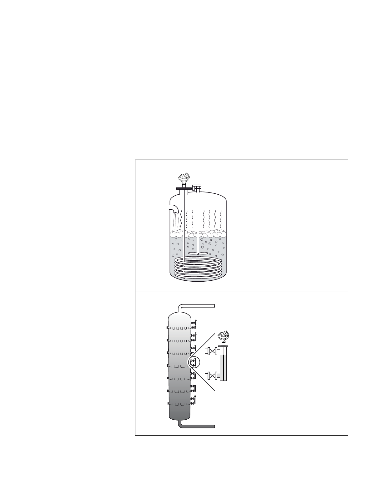
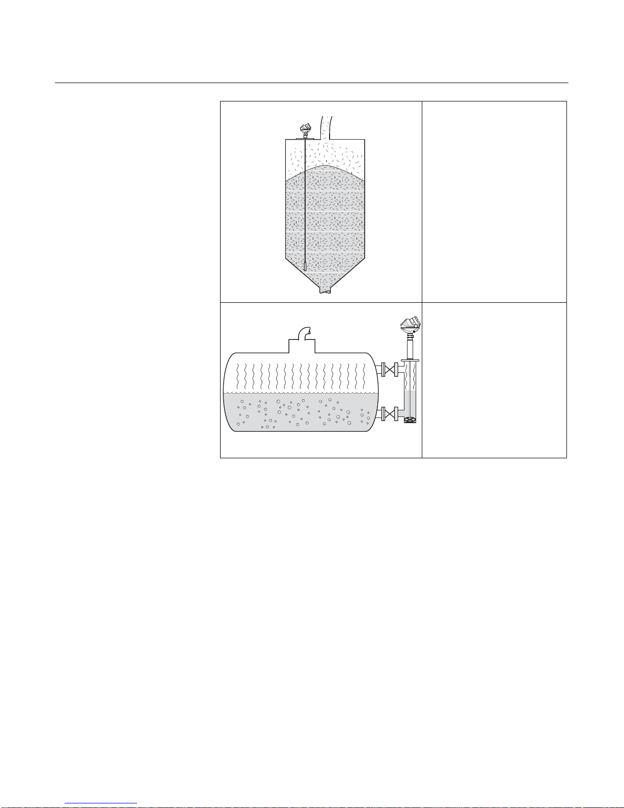
Figure 2-2. Application
examples
The Rosemount 5300 transmitter
works well in boiling conditions with
vapor and turbulence. If there are
disturbing objects in the vicinity of the
transmitter, the coaxial probe is
particularly suitable.
2-2
The Rosemount 5300 Series is well
suited for chamber applications, such
as distillation columns.
Page 17
Reference Manual
Oil
Oil
Water
00809-0100-4530, Rev BA
July 2009
Rosemount 5300 Series
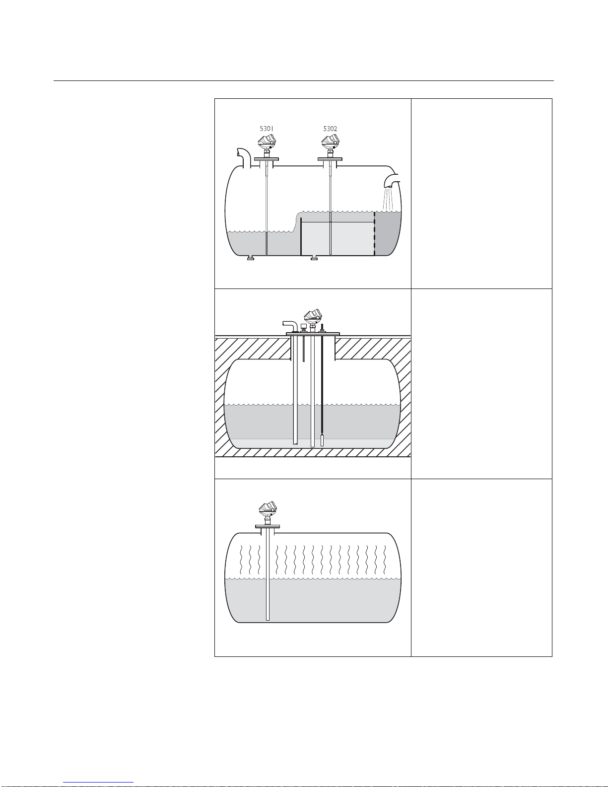
The Rosemount 5302 measures both
level and interface level in a separator
tank.
The Rosemount 5300 Series is a
good choice for underground tanks. It
is installed on the top of the tank with
the radar pulse concentrated near the
probe. It can be equipped with probes
that are unaffected by high and
narrow openings or nearby objects.
Guided wave radar technology
provides reliable measurements in
ammonia, LNG and LPG tanks.
2-3
Page 18
Rosemount 5300 Series
5303
Reference Manual
00809-0100-4530, Rev BA
July 2009
Model 5303, with a flexible single lead
probe, is the solution for solids,
powders and granules.
It measures independently of dust,
angled surfaces etc.
The Rosemount 5300 with Dynamic
Vapor Compensation will
automatically compensate for
dielectric changes in high pressure
steam applications and maintain the
level accuracy.
2-4
Page 19
Reference Manual
Radar Electronics
Probe
Dual Compartment Housing
Cable Entry:
½" NPT.
Optional adapters:
M20, eurofast,
minifast
Threaded
Process
Connections
Flanged
Process
Connections
BSP (G)
NPT
Co
a
x
ia
l
F
le
x
ib
l
e
T
w
in L
e
ad wi
t
h
we
ig
ht
Rigid
Tw in Lead
Ri
g
id
Si
n
g
le
Lea
d
F
l
ex
i
b
le
Sing
le
Lea
d
w
i
th weig
h
t
HTHP
Version
00809-0100-4530, Rev BA
July 2009
Rosemount 5300 Series
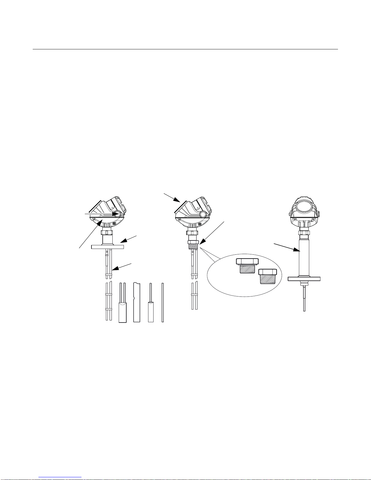
COMPONENTS OF THE
TRANSMITTER
Figure 2-3. Transmitter
components.
The Rosemount 5300 Series Radar T ransmitte r has an aluminum or st ainless
steel (SST) transmitter housing containing advan ced electronics and software
for signal processing. SST housing is preferred for harsh environment
applications, such as off-shore platforms or other location s where the housing
can be exposed to corrodents, such as salt solutions and caustics.
The radar electronics produces an electromag netic pulse that is guided by the
probe. It comes with flange, threaded or Tri-Clamp process connection.
There are different probe types available for various applications: Rigid Twin
Lead, Flexible Twin Lead, Rigid Single Lead, Flexible Single Lead, and
Coaxial.
2-5
Page 20

Rosemount 5300 Series
Dual Compartment
Housing
U-bolt Bracket
Clamping Brackets
M50 nut
Cable Remote Connection
Reference Manual
00809-0100-4530, Rev BA
July 2009
Figure 2-4. Remote Housing
components.
Remote Housing allows for the transmitter head to be mounted separately
from the probe.
2-6
Page 21
Reference Manual
4-20 mA/HART
Rosemount 751
Field Signal Indicator
Rosemount 375
Field
Communicator
HART modem
5300 SERIES
RADAR
TRANSMITTER
DCS
Rosemount
333 HART
Tri-Loop
3 x 4-20 mA
Rosemount Radar Master
or
AMS Suite
Integral
Display
Note! For HART communication, a
minimum load resistance of
250 within the loop is required.
00809-0100-4530, Rev BA
July 2009
Rosemount 5300 Series
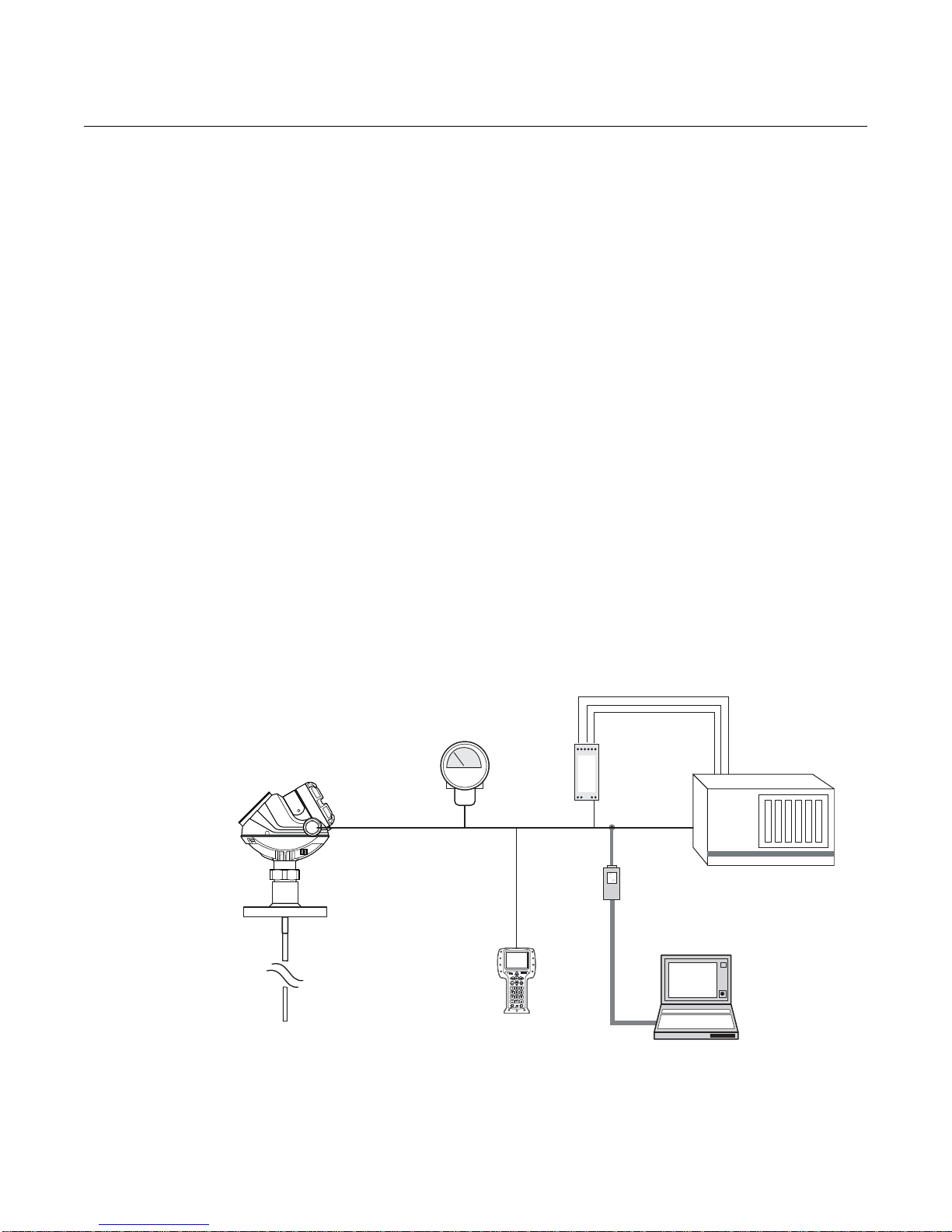
SYSTEM
ARCHITECTURE
Figure 2-5. HART system
architecture
The Rosemount 5300 Series Radar Transmitter is loop-powered, and it uses
the same two wires for both power supply and output signal. The output is a
4-20 mA analog signal superimposed with a digital HART
®
or FOUNDATION™
Fieldbus signal.
By using the optional Rosemount 333 HART Tri-loop, the HART signal can
convert up to three additional 4-20 mA analog signals.
With the HART protocol multidrop configuration is possible. In this case,
communication is restricted to digital, since current is fixed to the 4 mA
minimum value.
The transmitter can be connected to a Rosemount 751 Field Signal Indi ca tor,
or it can be equipped with an integral display.
The transmitter can easily be configured using a Rosemount 375 Field
Communicator or a PC with the Rosemount Radar Master software.
Rosemount 5300 Series transmitters can also be configured with the AMS
®
Suite and DeltaV™ software, and other tools supporting Electronic Device
Description Language (EDDL) functionality.
For HART communication a minimum load resistance o f 250 within the loop
is required.
2-7
Page 22
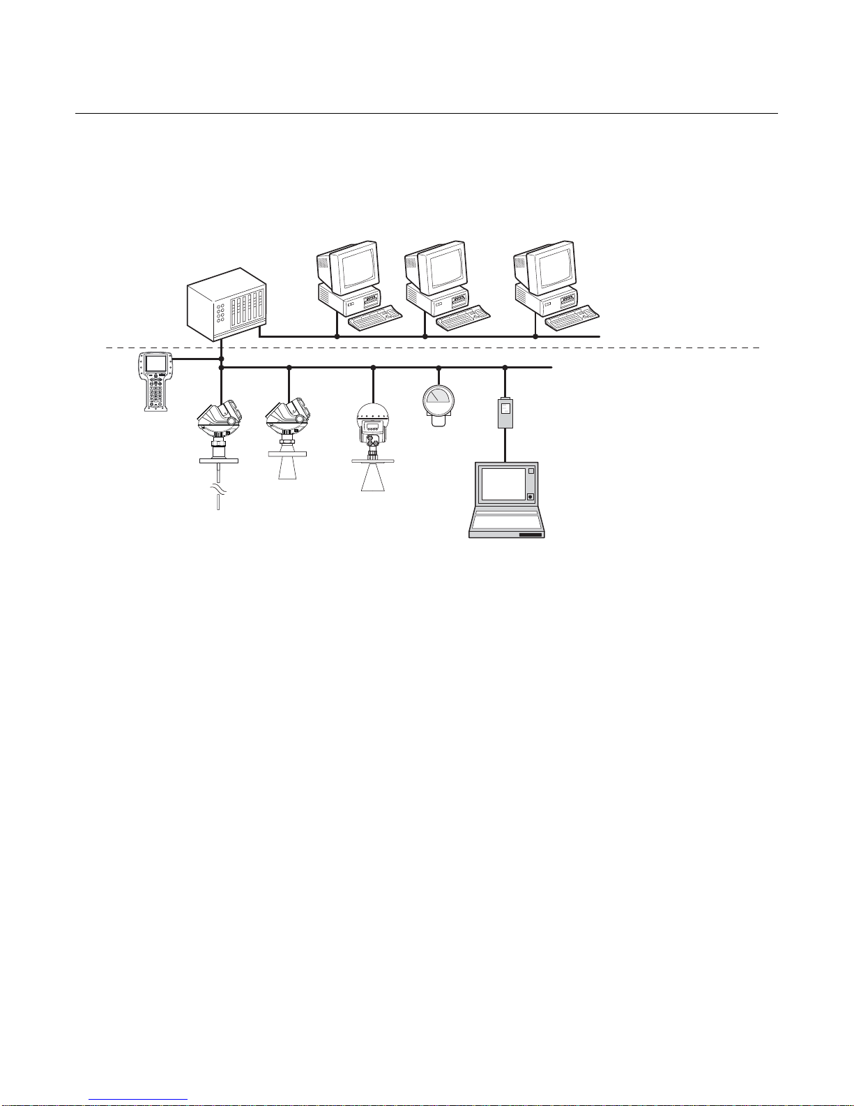
Rosemount 5300 Series
Host/DCS system (e.g. DeltaV®)
375 Field
Communicator
Maintenance
Rosemount 5300
Rosemount 5400
Rosemount 5600
PC with Rosemount
Radar Master
Fieldbus modem
H2 - High Speed Field Bus
H1 - Low Speed Field Bus
6234 ft (1900 m) maximum
(depending on cable
characteristics)
Display
Note:
Intrinsically safe
installations may
allow fewer devices
per I.S. barrier due to
current limitations.
Figure 2-6. FOUNDATION
Fieldbus system architecture
Reference Manual
00809-0100-4530, Rev BA
July 2009
2-8
Page 23
Reference Manual
00809-0100-4530, Rev BA
July 2009
Rosemount 5300 Series
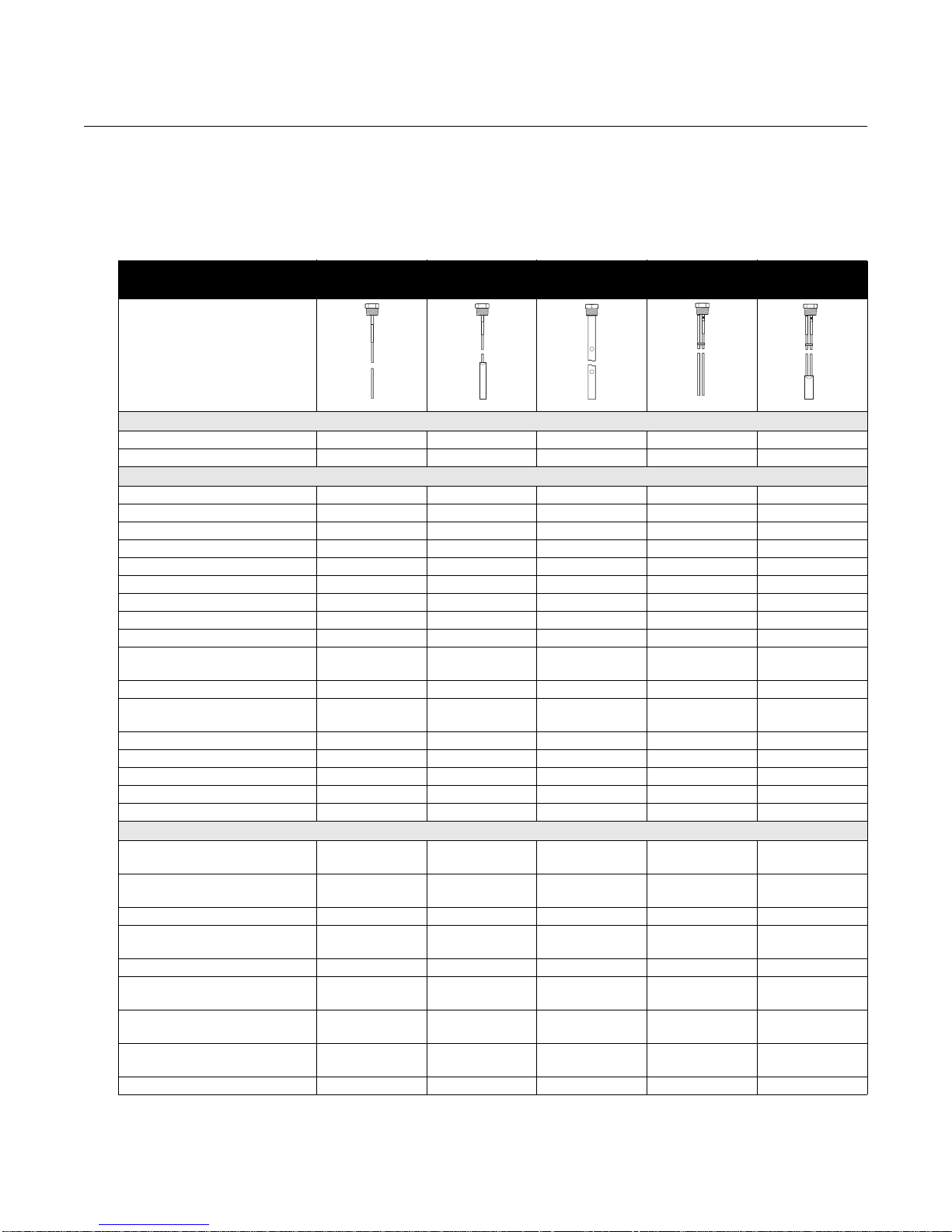
PROBE SELECTION
GUIDE
The following guidelines should be used to choose the appropriate probe for
the Rosemount 5300 transmitter:
Table 2-1. Probe selection guide.
Rigid Single
Lead
G=Good
NR=Not Recommended
AD=Application Dependent
(consult your local Emerson
Process Management
representative)
Level G G G G G
Interface (liquid/liquid) G G G G G
Changing density G G G G G
Changing dielectric
Wide pH variations G G G G G
Pressure changes G G G G G
Temperature changes G G G G G
Condensing vapors G G G G G
Bubbling/boiling surfaces G AD G G G
Foam (mechanical avoidance) NR NR AD NR NR
Foam (top of foam measurement) AD AD NR AD AD
Foam (foam and liquid
measurement)
Clean liquids G G G G G
Liquid with very low dielectric
constants, see also Table 2-4.
Coating/sticky liquids AD AD NR NR NR
Viscous liquids AD G NR AD AD
Crystallizing liquids AD AD NR NR NR
Solids, granules, powders AD G NR NR NR
Fibrous liquids G G NR NR NR
Probe is close (<12 in./30 cm) to
tank wall / disturbing objects
Probe might touch tank wall,
nozzle or disturbing objects
Turbulence G AD G G AD
Turbulent conditions causing
breaking forces
Tall, narrow nozzles AD AD G AD AD
Angled or slanted surface
(viscous or solids materials)
Liquid or vapor spray might touch
probe above surface
Disturbing Electromagnetic
interference in tank
Cleanability of probe G G NR AD AD
(1) For overall level applications, a changing dielectric has no effect on the measurement. For interface measurements, a changing dielectric for the
top fluid will degrade the accuracy of the interface measurement.
(2) Limited measuring range.
(1)
GGGGG
AD AD NR AD AD
GG
Tank Environment Considerations
AD AD G G G
NR NR G NR NR
NR AD NR NR AD
G G NR AD AD
NR NR G NR NR
AD AD G AD AD
Flexible Single
Lead
Measurements
Process Medium Characteristics
(2)
Coaxial Rigid Twin Lead Flexible Twin
GGG
Lead
(2)
2-9
Page 24
Reference Manual
4mA
20mA
Upper Transition Zone
Lower Transition Zone
Range 0 -100 %
Maximum
Recommended
Measuring Range
Upper Reference Point
00809-0100-4530, Rev BA
Rosemount 5300 Series
July 2009
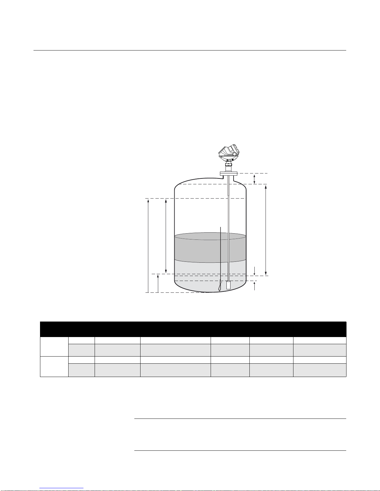
Transition Zones The measuring range depends on probe type and product properties, and is
limited by the Upper and Lower Transition Zones. In these zones,
measurement accuracy may be reduced. The Upper Transition Zone is the
minimum measurement distance between the upper reference point and the
product surface. At the end of the probe, the measuring accuracy is reduced
in the Lower Transition Zone. The Transition Zones vary depending on
probe type and product.
Figure 2-7 illustrates how the measuring range is related to the Transition
Zones:
Figure 2-7. Transition Zones
Table 2-2. Transition Zones for
different probe types and dielectric
constants
Dielectric
Constant
(1)
Upper
Transition
Zone
(2)
Lower
Transition
Zone
(1) The distance from the upper reference point where measurements have reduced accuracy, see picture above.
(2) The distance from the lower reference point where measurements have reduced accuracy, see picture above.
(3) The measuring range for the PTFE covered Flexible Single Lead probe includes the weight. For low dielectric media, special configuration may be
required.
(4) Note that the weight length adds to non-measurable area and is not included in the t able. See “Dimensional Drawings” on page A-9.
(5) If using a metal centering disc, the lower transition zone is up to 8 in. (20 cm). If using a PTFE centering disc, the lower transition zone is not affected.
80 4.3 in. (11 cm) 4.3 in. (11 cm) 4.3 in. (11 cm) 4.3 in. (11 cm) 4.7 in. (12 cm)
80 2 in. (5 cm) 0 in. (0 cm)
Rigid Single Lead Flexible Single Lead Coaxial Rigid Twin Lead Flexible Twin Lead
2 6.3 in. (16 cm) 7.1 in. (18 cm) 4.3 in. (11 cm) 5.5 in. (14 cm) 5.5 in. (14 cm)
2 2.8 in. (7 cm)
2 in. (5 cm) - long weight
(5)
3.2 in. (8 cm) - short weight
(4)(3)
0.4 in. (1 cm) 1.2 in. (3 cm) 2 in. (5 cm)
(4)
(4)
2 in. (5 cm) 4 in. (10 cm) 5.5 in. (14 cm)
NOTE!
Measurements in the Transition Zones may be non-linear, or have reduced
accuracy. It is recommended the 4-20 mA points be set between the
Transition Zones.
2-10
(4)
(4)
Page 25
Reference Manual
00809-0100-4530, Rev BA
July 2009
Rosemount 5300 Series
PROCESS
CHARACTERISTICS
The Rosemount 5300 Series has high sensitivity because of its advanced
signal processing and high signal to noise ratio. This makes it able to handle
various disturbances, however, the following circumstances should be
considered before mounting the transmitter.
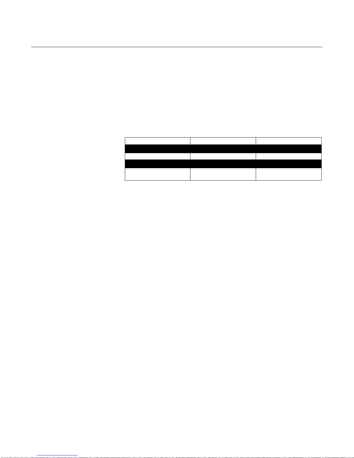
Coating Heavy coating of the probe should be avoided since it may decrease the
sensitivity of the transmitter and lead to measurement errors. In viscous or
sticky applications, periodic cleaning may be required.
For viscous or sticky applications, it is important to choose a suitable probe:
Table 2-3. Probe type guide for
different product viscosity
Coating not recommended Thin coating allowed, but no
(1) Consult your local Emerson Process Management representatvie for agitation/turbulence and high
(2) Be precautious in HTHP viscous or crystallizing media applications where temperature at instr ument
Maximum measurement error due to coating is 1-10% depending on probe
type, dielectric constant, coating thickness and coating height above product
surface.
Coaxial Twin Lead Single Lead
Maximum viscosity
500 cP 1500 cP 8000 cP
Coating/Build-up
Coating allowed
bridging
viscous products.
connection is significantly lower than process temperature with risk of coating in the upper part of
probe that may reduce the measurement signal. Consider using HP or STD probes in such
applications.
(1)(2)
Signal Quality Metrics (SQM) diagnostic option can give an indication of how
good the surface signal is compared to the noise, and when to clean the
probe.
Bridging Heavy product coating results in bridging between the two probes in a twin
lead version, or between the pipe and inner rod for coaxial probes, and may
cause erroneous level readings, so it must be prevented. A single lead probe
is recommended in these situations.
Foam The Rosemount 5300 Series Radar T ransmitter measurement in foamy
applications depends on the foam properties; light and airy or dense and
heavy, high or low dielectrics, etc. If the foam is conductive and creamy, the
transmitter may measure the surface of the foam. If the foam is less
conductive the microwaves may penetrate the foam and measure the liquid
surface.
Vapor In some applications, such as high pressure boiling water, there is a heavy
vapor above the product surface that could influence the level measurement.
The Rosemount 5300 Series Radar Transmitter can be configured to
compensate for the influence of vapor.
Boiling Hydrocarbons For products with very low dielectric constants, such as boiling hydrocarbons
and solids, the threshold may need to be lowered, and/or the Probe End
Projection (PEP) function activated.
2-11
Page 26
Reference Manual
Level
Interface Level
Level = Interface Level
5302
5301
00809-0100-4530, Rev BA
Rosemount 5300 Series
July 2009
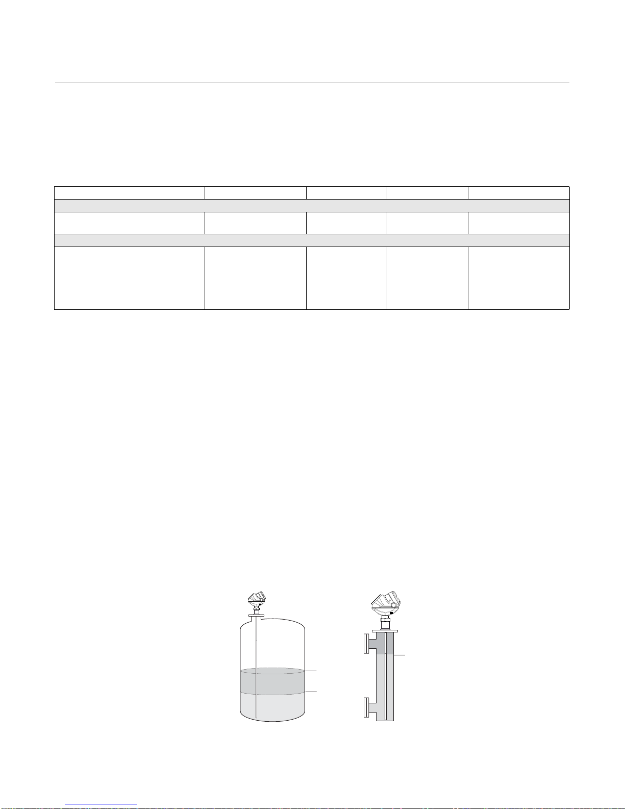
Measuring Range The measuring range differs depending on probe type and characteristics of
the application. Table 2-4 can be used as a guideline for clean liquids.
See Appendix A: Reference Data for the measuring range when using
Remote Housing.
Table 2-4. Measuring Range
Rigid Single Lead Flexible Single Lead
Maximum Measuring Range
9 ft 10 in. (3 m) - for 8 mm probes
14 ft 9 in. (4.5 m) - for 13 mm probes
1.4 (1.25 if installed in a metallic
bypass or stilling well)
(1) The probe end projection software function will improve the minimum die lectric const ant. Consult you local Emer son Process Managemen t representa tive
for details.
(2) Measuring range may be lower depending on installation.
(1)(2)
164 ft (50 m) 19 ft 8 in. (6 m) 9 ft 10 in. (3 m) 164 ft (50 m)
Minimum Dielectric Constant at Maximum Measuring Range
1.4, up to 49 ft (15 m)
1.8, up to 82 ft (25 m)
2.0, up to 115 ft (35 m)
3, up to 138 ft (42 m)
4, up to 151 ft (46 m)
6, up to 164 ft (50 m)
(1)
(1)
(1)
(1)
Coaxial Rigid Twin Lead Flexible Twin Lead
1.2 (Standard)
1.4 (HP/C)
2.0 (HTHP)
1.4 1.4, up to 82 ft (25 m)
2.0, up to 115 ft (35 m)
2.5, up to 131 ft (40 m)
3.5, up to 148 ft (45 m)
6, up to 164 ft (50 m)
The maximum measuring range differs based on application according to:
• Disturbing objects close to the probe
• Media with higher dielectric constant (
) has better reflection and a
r
longer measuring range
• Surface foam and particles in the tank atmosphere might affect
measuring performance
• Heavy coating / contamination on the probe may redu ce the measuring
range and cause erroneous level readings
• Disturbing EMC environment in tank
• Tank material (e.g. concrete or plastic) for measurements with single
lead probes
(1)
(1)
(1)
Interface Rosemount 5302 is the ideal choice for measuring the level of oil, and the
Figure 2-8. Interface
measurement with a Rosemount
5302 and a Rosemount 5301
(fully submerged probe).
2-12
interface of oil and water , or other liquids with significan t dielectric dif ferences.
Rosemount 5301 can also be used for interface measurement in applica tions
where the probe is fully submerged in the liquid.
Page 27
Reference Manual
1
35
7
9
11
0
16 (5)
33 (10)
49 (15)
66 (20)
82 (25)
98 (30)
115 (35)
80
40
20
10
Upper product dielectric constant
Maximum Upper Product
Thickness, ft (m)
Lower product
dielectric constant
Flexible Single Lead
00809-0100-4530, Rev BA
July 2009
Rosemount 5300 Series
For measuring interface level, the transmitter uses the residual wave of the
first reflection. Part of the wave, not reflected at the upper product surface,
continues until it is reflected at the lower product surface. The speed of this
wave depends fully on the dielectric constant of the upper product.
To measure interface, the following criteria have to be fulfilled:
• The dielectric constant of the upper prod uct must be known and sho uld
be constant. The Rosemount Radar Master software has a built- in
dielectric constant calculator to assist in determining the dielectric
constant of the upper product. (see “Dielectric Constant/Dielectr ic
Range” on page 5-23)
• The upper product must have a lower dielectr ic constant than the lower
product to have a distinct reflection
• The difference between the dielectric constants for the two products
must be greater than 6
• The maximum dielectric constant for the upper product: 10 for the
coaxial probe, 7 for the twin lead, and 8 for the single lead probes
• The upper product thickness must be greater than 5.1 in. (0.13 m) for
all probes, except the HTHP coaxial probe, which requires 8 in. (0.2 m),
to distinguish the echoes of the two liquids
The maximum allowable upper product thickness/measuring range is
primarily determined by the dielectric constants of the two liquids.
Target applications include interfaces between oil / oil-like and water /
water-like liquids with a low (<3) dielectric constant for the upper product and
a high (>20) dielectric constant for the lower product.
For such applications, the maximum measuring range is limited by the length
of the coaxial, rigid twin, and rigid single lead probes.
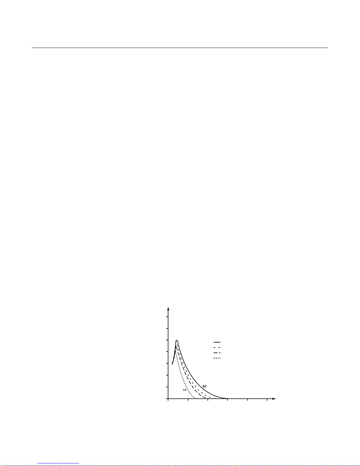
For flexible probes, the maximum measuring range is reduced by the
maximum upper product thickness, according to the diagram below . However,
characteristics may vary between the different applicat ion s .
Figure 2-9. Maximum Upper
Product thickness for the
Flexible Single Lead probe.
2-13
Page 28
Rosemount 5300 Series
Lower product
dielectric constant
Upper product dielectric constant
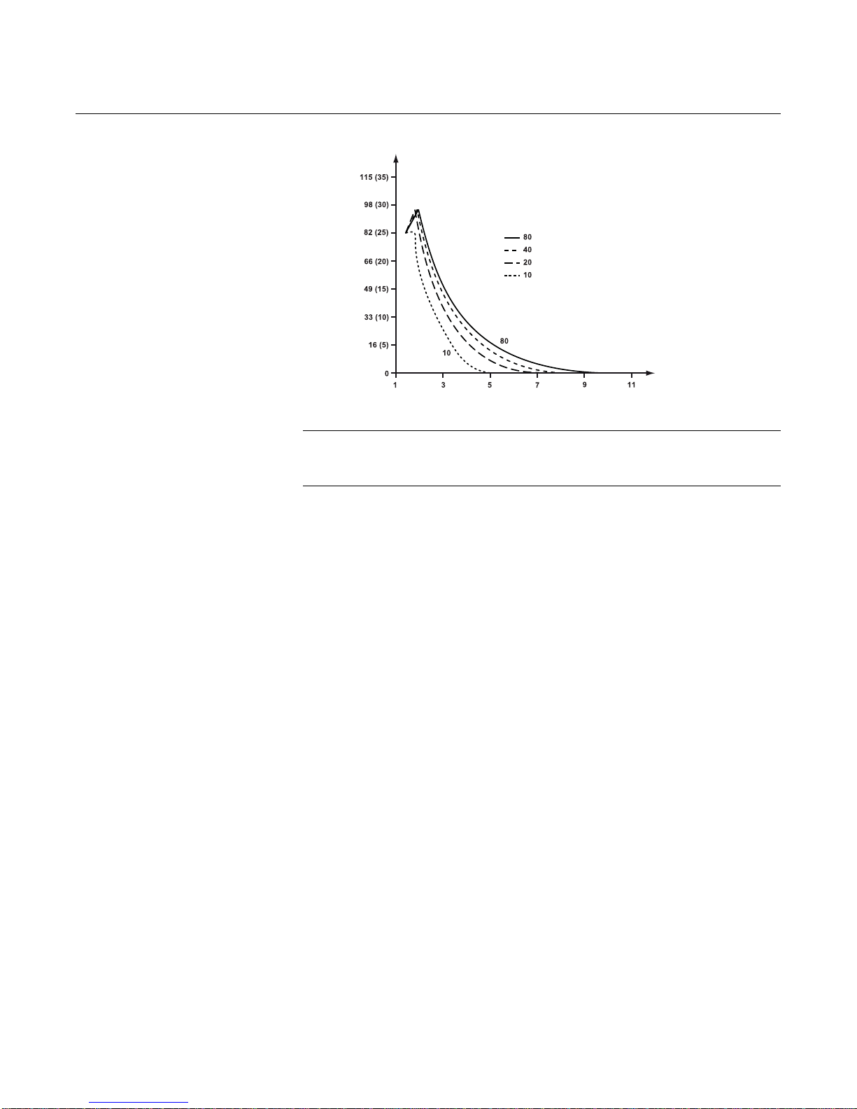
Flexible Twin Lead
Maximum Upper Product
Thickness, ft (m)
Figure 2-10. Maximum Upper
Product thickness for the
Flexible Twin Lead probe.
NOTE!
Maximum distance to the interface = 164 f t.(50 m) - Maximum Upper Product
Thickness.
Reference Manual
00809-0100-4530, Rev BA
July 2009
Emulsion Layers
Sometimes an emulsion layer (mix of the products) forms between the two
products and can affect interface measurements. For assistance with
emulsion applications, consult your local Emerson Process Management
representative.
V E SSEL
CHARACTERISTICS
Heating Coils, Agitators Because the radar signal is transmitted along a probe, the Rosemount 5300
Radar transmitter is generally not affected by objects in the tan k. Avoid
physical contact with metallic objects when Twin Lead or Single Lead probes
are used.
Avoid physical contact between probes and agitators, as well as applications
with strong fluid movement, unless the probe is anchored. If the probe is able
to move 1 ft. (30 cm) from any object, such as an agitator, during operation,
the probe tie-down is recommended.
To stabilize the probe for side forces, a weight may be hung at the probe end
(flexible probes only) or fix/guide the probe to the tank bottom.
Tank Shape The guided wave radar transmitter is insensitive to tank shape. Since the
radar signal travels along a probe, the shape of the tank bottom has virtually
no effect on the measurement performance. Th e transmitter can handle flat or
dish-bottom tanks.
2-14
Page 29
Reference Manual
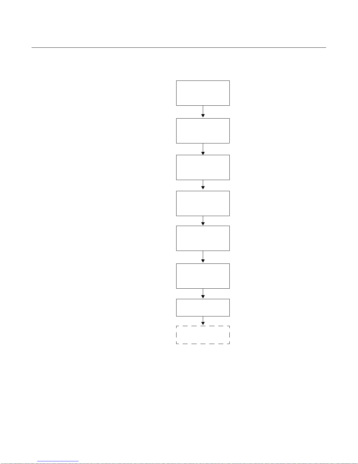
Review Mounting
Considerations
(see page 3-3)
Mount the transmitter
(see page 3-15)
Wire the transmitter
(see Section 4:
Electrical Installation)
Make sure covers
and cable/conduit
connections are tight
Power up the
transmitter
Configure the
transmitter
(see Section 5:
Configuration)
Verify measurements
Set the Write
Protection
00809-0100-4530, Rev BA
July 2009
Rosemount 5300 Series
INSTALLATION
PROCEDURE
Follow these steps for proper installation:
2-15
Page 30

Rosemount 5300 Series
Reference Manual
00809-0100-4530, Rev BA
July 2009
2-16
Page 31

Reference Manual
00809-0100-4530, Rev BA
July 2009
Rosemount 5300 Series
Section 3 Mechanical Installation
Safety messages . . . . . . . . . . . . . . . . . . . . . . . . . . . . . . . . . page 3-1
Mounting Considerations . . . . . . . . . . . . . . . . . . . . . . . . .page 3-3
Mounting . . . . . . . . . . . . . . . . . . . . . . . . . . . . . . . . . . . . . . . page 3-15
SAFETY MESSAGES Procedures and instructions in this section may require special precautions to
ensure the safety of the personnel performing the operations. Information that
raises potential safety issues is indicated by a warning symbol ( ). Please
refer to the following safety messages before performing an operation
preceded by this symbol.
Failure to follow safe installation and servicing guidelines could result in death or
serious injury:
Make sure only qualified personnel perform the installation.
Use the equipment only as specified in this manual. Failure to do so may impair the
protection provided by the equipment.
Do not perform any services other than those contained in this manual unless you are
qualified.
Process leaks could result in death or serious injury.
Make sure that the transmitter is handled carefully. If the Process Seal is damaged, gas
might escape from the tank if the transmitter head is removed from the probe.
www.rosemount.com
High voltage that may be present on leads could cause electrical shock:
Probes covered with plastic and/or with plastic discs may generate an ignition-capable
level of electrostatic charge under certain extreme conditions. Therefore, when the
probe is used in a potentially explosive atmosphere, appropriate measures must be
taken to prevent electrostatic discharge.
Page 32

Rosemount 5300 Series
Any substitution of non-authorized parts or repair, other than exchanging the complete
transmitter head or probe assembly, may jeopardize safety and is prohibited.
Unauthorized changes to the product are strictly prohibited as they may unintentionally
and unpredictably alter performance and jeopardize safety. Unauthorized changes that
interfere with the integrity of the welds or flanges, such as making additional
perforations, compromise product integrity and safety. Equipment ratings and
certifications are no longer valid on any products that have been damaged or modified
without the prior written permission of Emerson Process Management. Any continued
use of product that has been damaged or modified without prior written authorization is
at the customer's sole risk and expense.
Reference Manual
00809-0100-4530, Rev BA
July 2009
3-2
Page 33

Reference Manual
Avoid nozzles with reducer
(unless using Coaxial probe)
UNZ
H
D
00809-0100-4530, Rev BA
July 2009
Rosemount 5300 Series
MOUNTING
CONSIDERATIONS
Before installing the Rosemount 5300 Series Radar Transmitter, consider
specific mounting requirements, vessel and process characteristics.
For Remote Housing installation see Appendix D: Remote Mounting.
Process Connection The Rosemount 5300 Series has a threaded con nection for easy mounting on
a tank roof. It can also be mounted on a nozzle by using differen t flanges.
Threaded Connection
Figure 3-1. Mounting on tank
roof using threaded connection.
Mounting on tank roof.
Figure 3-2. Mounting in nozzles
Flange Connection on Nozzles
3-3
Page 34

Rosemount 5300 Series
The transmitter can be mounted in nozzles by using an appropr iate flange.
The nozzle sizes given in Table 3-1 show the recommended dimensions. For
small nozzles, it may be necessary to increase the Upper Null Zone (UNZ) to
reduce the measuring range in the upper p art of the tank. Amplitude
Threshold adjustments may also be needed in th is case. A Trim Near Zone is
recommended in most nozzle installations, for example, when there are
disturbing obstacles in the near zone. See Appendix C: Handling of
Disturbances from Nozzle on page C-4.
NOTE!
The probe should not contact the nozzle, with the exception of the Coaxial
Probe. If the nozzle diameter is less than recommended, the mea suring range
may be reduced.
Table 3-1. Nozzle
considerations
Recommended
Nozzle Diameter (D)
Minimum Nozzle
Diameter (D)
Recommended
Nozzle Height (H)
(1) The Trim Near Zone function may be necessary or an Upper Null Zone setup may be required to mask
the nozzle.
(2) Longer nozzles may be used in certain applications. Consult your local Emerson Process
Management representative for details.
(3) When using single flexible probes in tall nozzles, it is recommended to use t he Long Stud (LS).
Reference Manual
00809-0100-4530, Rev BA
July 2009
Single (Rigid/Flexible) Coaxial Twin (Rigid/Flexible)
6 in. (150 mm)
(1)
(2)
2 in. (50 mm)
4 in. + Nozzle Diameter
> Probe Diameter 4 in. (100 mm)
> Probe Diameter 2 in. (50 mm)
(3)
N/A
4 in. + Nozzle
Diameter
3-4
Page 35

Reference Manual
Metal flange Ø>2
in./DN50
Metal sheet
Ø>8 in./200 mm
00809-0100-4530, Rev BA
July 2009
Figure 3-3. A single flexible
probe with a long stud.
Rosemount 5300 Series
A long stud - 10 in. (250 mm) - is recommen ded for sin gle flexible probes in a
tall nozzle.
Long Stud
10 in. (250 mm)
Installation of Single
Lead Probes in
Non-metallic Vessels
Figure 3-4. Mounting in
non-metallic vessels.
NOTE!
For single lead probes, avoid 10-in. (250 mm)/DN250 or larger diameter
nozzles, especially in applications with low dielectric constant. An alternative
is to install a smaller nozzle inside the nozzle.
For optimal single lead probe performance in non-metallic (plastic) vessels,
the probe must be mounted with a metal flange, or screwed in to a metal
sheet (d>8 in./200 mm), if the threaded version is used.
Electromagnetic disturbances should be kept to a minimum since they may
affect measurement performance.
3-5
Page 36

Rosemount 5300 Series
Metal
Installation in Concrete
Silos
Reference Manual
00809-0100-4530, Rev BA
July 2009
Considerations for Solid
Applications
The flexible single lead probe is recommended for solids and is available in
two versions to handle different loads and lengths:
• 0.16 in. (4 mm) diameter
Tensile strength is minimum 2698 lb (12 kN)
Collapse load is maximum 3597 lb (16 kN)
• 0.24 in. (6 mm) diameter
Tensile strength is minimum 6519 lb (29 kN)
Collapse load is maximum 7868 lb (35 kN)
Keep the following in mind when planning installation of the Rosemount 5300
in solid applications:
• There might be considerable down-pull forces on silo roofs caused by
the media, so the silo roof must withstand the maximum probe tensile
load
• The tensile load depends on silo size, material density, and the friction
coefficient. Forces increase with the buried length, the silo, and probe
diameter
• In critical cases, such as for products with a risk for build-up, use a 0.24
in. (6 mm) probe
• Depending on position, forces on probes are two to ten times greater
on probes with tie-down, than on probes with ballast weights
Guidelines for the tensile load from free-flowing solids acting on a suspended
probe without any tie-down or weight in a smooth metallic wall silo as shown
in Table 3-2. A safety factor of 2 is included for the figures. Consult your local
Emerson Process Management representative for more information.
(1)
3-6
(1) The weight should not be fixed for probe 100 ft (30 m) or longer.
Page 37

Reference Manual
Make sure that the probe
does not come into
contact with the chamber
wall, e.g. by using a
centering disk.
00809-0100-4530, Rev BA
July 2009
Table 3-2. Pulling force on probe installed in tanks with different products
Rosemount 5300 Series
Material Tensile load for 0.16 in. (4 mm)
Probe length 49 ft (15 m) Probe length 115 ft (35 m) Probe length 49 ft (15 m) Probe length 115 ft (35 m)
Tank Ø=
10 ft (3 m)
Wheat 670 (3) 1120 (5) 1800 (8) 4500 (20)
Polypropylene
Pellets
Cement 900 (4) 2020 (9) 2470 (11) 7310 (32.5)
340 (1.5) 670 (3) 810 (3.6) 2360 (10.5) 450 (2) 920(4.1) 1190 (5.3) 3510 (15.6)
flexible single lead probe, lb (kN)
Tank Ø=
39 ft (12 m)
Tank Ø=
10 ft (3 m)
Tank Ø=
39 ft (12 m)
Exceeds tensile
strength limit
Exceeds tensile
strength limit
NOTE!
For environments where electrost atic discharge s (p lastics) ar e li ke ly to occur,
it is recommended that the probe end is grounded.
Mounting in Chamber/
Still Pipe
The chamber is also known as bridle, side pipe, bypass pipe, and cage.
Dimensioning the chamber correctly and selecting the appropriate probe is
key to the success in these applications.
To prevent the probe from contacting the wall, centering discs are available
for the Rigid Single, Flexible Single, and Flexible Twin Lead Probes. The disc
is attached to the end of the probe, and thus keeps the probe centered in the
chamber. See also “Mou nting a Centering Disc for Pipe Installations“ on
page 3-25.
Tensile load for 0.24 in. (6 mm)
flexible single lead probe, lb (kN)
Tank Ø=
10 ft (3 m)
900 (4) 1690 (7.5) 2810 (12.5) 6740 (30)
1350 (6) 2920 (13) 3600 (16) 10790 (48)
Tank Ø=
39 ft (12 m)
Tank Ø=
10 ft (3 m)
Tank Ø=
39 ft (12 m)
Exceeds tensile
strength limit
Exceeds tensile
strength limit
NOTE!
To avoid disturbances from object near the pipe, metal-pipes are preferred,
especially in applications with low dielectric constant.
3-7
Page 38

Rosemount 5300 Series
Rigid Single
Flexible Single
N
L
Ø
Ø
Figure 3-5. Mounting Single
Probe in Chamber/Still Pipe
Inlet pipe diameter N<Ø. Effective measuring range L12 in. (300 mm).
Table 3-3. Recommended and
minimum chamber/still pipe
diameters for different probes.
Probe Type Recommended Diameter Minimum Diameter
Rigid Single 3 or 4 in. (75 or 100 mm) 2 in. (50 mm)
Flexible Single
Rigid Twin
Flexible Twin
Coaxial 3 or 4 in. (75 or 100 mm) 1.5 in. (37.5 mm)
(1) The center rod must be placed more than 0.6 in. (15 mm) away from the pipe wall.
The recommended chamber diameter is 3 in. (75 mm) or 4 in. (100 mm).
Chambers with a diameter less than 3 in. (75 mm) may cause problems with
build-up and it may also be difficult to avoid contact between chamber wall
and probe. Chambers larger than 6 in. (150 mm) can be used but provide no
advantages for radar measurement.
Reference Manual
00809-0100-4530, Rev BA
July 2009
4 in. (100 mm) Consult your local Emerson
Process Management
(1)
(1)
3 or 4 in. (75 or 100 mm) 2 in. (50 mm)
4 in. (100 mm) Consult your local Emerson
representative
Process Management
representative
3-8
It is recommended that single probes are used with the Rosemount 5300
Series. Other probe types are more susceptible to build-up and are not
recommended.
(1)
An exception is with liquefied gas > 40 bar when the coaxial
probe should be used.
The probe must not touch the chamber wall, should extend the full height of
the chamber, but not touch the bottom of the chamber. Probe type selection
depends on probe length:
Less than 14.7 ft (4.5 m): Rigid Single Probe is recommended. Use a
centering disc for a probe > 3.3 ft. (1 m). If installation requires less
head-space, use a Flexible Single Probe with a weight and centering disc.
(2)
More than 14.7 ft (4.5 m): Use Flexible Single Probe with a weight and
centering disc.
(1) The single probe creates a virtual coaxial probe with the chamber as the outer tube. The
extra gain provided by the twin and coaxial probes is not necessary; the electronics in the
Rosemount 5300 Series is very sensitive and is not a limiting factor.
(2) The transition zones and the height of the weight limit the use of single flexible probes
shorter than 3 ft. (1 m). If using the flexible probe, the short weight is recommended.
Page 39

Reference Manual
Side-and-Side
dimension
Side-and-Bottom
dimension
Centre-to-Centre
Centre-to-Centre
00809-0100-4530, Rev BA
July 2009
Figure 3-6. Insulated Chamber.
Rosemount 5300 Series
A short weight for the single flexible 0.16 in. (4 mm) SST probe can be used
for measuring close to the probe end. The height is 2 in. (50 mm) and the
diameter is 1.5 in.
(37.5 mm). Option code W2.
For hot applications, the chamber should always be insulated to prevent
personal injuries and to reduce the amount o f energy needed for heating . See
Figure 3-6. It is often an advantage, and sometimes even required, for the
radar measurement:
• In hot applications, insulation reduces the amount of condensation,
since it prevents the upper part of the chamber from becoming a cold
spot
• Insulation prevents product solidification inside the chamber, and
clogging of the inlet-pipes
See page 3-14 for more information.
When mounting in a Rosemount 9901 chamber, the probe length to use can
be calculated with these formulas:
Side-and-Side dimension: Probe length = Centre-to-Centre dimension +
19 in. (48 cm)
Side-and-Bottom dimension: Probe length = Centre-to-Centre dimension +
4 in. (10 cm)
3-9
Page 40

Rosemount 5300 Series
Replace
chamber flange
Displacer length
Probe
length
NOTE!
The formulas are not valid when using Dynamic Vapor Compensation probes.
Reference Manual
00809-0100-4530, Rev BA
July 2009
Replacing a Displacer in
an Existing Displacer
Chamber
A Rosemount 5300 Series transmitter is the perfect replacement for an
existing displacer chamber. To simplify installation, proprietary flanges are
offered to allow for using the same chambers.
Rosemount 5300 benefits
• No moving parts: Less maintenance - dramatically reduce d cos ts, and
as a result, improved measurement availability
• Reliable measurement, that is independent of density, turbulence, and
vibrations
Considerations when changing to Rosemount 5300
When changing from a displacer to a Rosemount 5300 Series transmitter,
make sure to correctly match the 5300 Series flange choice and probe length
to the chamber. Both standard ANSI and EN (DIN), as well as proprietary
chamber flanges are available.
Table 3-4. Required Probe
Length Depending on Chamber
Manufacturers
3-10
Table 3-4 shows probe length guidelines.
Chamber Manufacturer Probe Length
Major torque-tube manufacture (249B,
249C, 2449K, 249N, 259B)
Masoneilan (Torque tube operated),
proprietary flange
Others - torque tube
Magnetrol (spring operated)
Others - spring operated Displacer + 19.7 in. (500 mm)
(1)
Displacer + 9 in. (229 mm)
Displacer + 8 in. (203 mm)
(2)
(3)
(1) If flushing ring is used, add 1 in. (25 mm).
(2) For other manufacturers, there are small variations. This is an approximate value,
actual length should be verified.
(3) Lengths vary depending on model, SG and rating, and should be verified.
Displacer + 8 in. (203 mm)
Displacer + between 7.8 in. (195 mm)
to 15 in. (383 mm)
Page 41

Reference Manual
00809-0100-4530, Rev BA
July 2009
Rosemount 5300 Series
Free Space For easy access to the transmitter, make sure it is mounted with sufficient
service space. For maximum measurement performance, the transmitter
should not be mounted close to the tank wall or near other object s in the tank.
If the probe is mounted close to a wall, nozzle or other tank obstruction, noise
may appear in the level signal. The minimum clearance shown in Table 3-5
and Table 3-6 is recommended:
Figure 3-7. Free Space
Requirement
Table 3-5. Recommended
minimum free space L to tank
wall or other objects in the tank
Table 3-6. Recommended
minimum free space L to tank
wall or other objects in the tank
for Single Lead probes
Coaxial Rigid Twin Flexible Twin
0 in. (0 mm) 4 in. (100 mm) 4 in. (100 mm)
Rigid Single/Flexible Single
4 in. (100 mm) Smooth metal wall.
20 in. (500 mm)
(1) When measuring in low DC (around 1.4). For higher DC, the recommended
free space is lower.
(1)
Disturbing objects such as pipes and beams,
concrete or plastic tank walls, rugged metal tank
walls.
3-11
Page 42

Rosemount 5300 Series
Inlet pipe
Heating coils
Agitator
Reference Manual
00809-0100-4530, Rev BA
July 2009
Recommended Mounting
Position for Liquids
Figure 3-8. Mounting Position
Tank conditions are recommended to be carefully considered when finding
the appropriate mounting position for the transmitter. The transmitter should
be mounted so the influence of disturbing objects is reduced to a minimum.
In case of turbulence, the probe may need to be anchored to the bottom. See
“Anchoring“ on page 3-22 for more information.
When mounting the transmitter the following guidelines should be considered :
• Do not mount close to inlet pipes
• Do not mount close to agitators. If the probe can move to within 30 cm
away from an agitator, a probe tie-down is recommended
• If the probe tends to sway from the turbulent conditions in the tank, the
probe should be anchored to the tank bottom
• Avoid mounting near heating coils
• The nozzle should not extend into the tank
• The probe should not come into contact with the nozzle or other object s
in the tank
• Position the probe so it is subject to a minimum of lateral force
NOTE!
Violent fluid movements can cause forces that could break rig id probes.
3-12
Page 43

Reference Manual
00809-0100-4530, Rev BA
July 2009
Recommended Mounting
for Solids
Rosemount 5300 Series
Consider the following guidelines when mounting the transmitter:
• Do not mount near inlet pipes in order to avoid product filling on the
probe
• Regularly check the probe for defects
• It is recommended that the vessel be empty during installation
• For concrete vessels, the distance (L) between the probe and the wall
should be at least 20 in. (500 mm)
• Stabilize the probe for side forces, by attaching the probe to the tank
bottom.
For solids, use the 0.24 in. (6 mm) probe, because of the higher tensile
strength. The probe should have a sag of
prevent probe damage. See “Anchoring“ on page 3-22 for more
information
• Avoid anchoring in solids tanks over 98 ft (30 m) in height since tensile
loads are much stronger for anchored probes, see “Considerations for
Solid Applications“ on page 3-6
• Product build-up on the silo walls near the probe may interfere with
measurements. Choose a mounting position where the probe is not in
contact with, or close to, the product build-up
1 in./100 in. (1 cm/m) to
3-13
Page 44

Reference Manual
Tank insulation
HTHP version
-320 (-196)
-40 (-40)
-40 (-40)
-17 (-27)
Ambient Temperature °F (°C)
Process
Temperature °F (°C)
00809-0100-4530, Rev BA
Rosemount 5300 Series
July 2009
Insulated Tanks When the Rosemount 5300 is installed in high temperature applications,
consider the maximum ambient temperature. Tank insulation should not
exceed 4 in. (10 cm).
Figure 3-9. Ambient temperature
vs. process temperature.
3-14
Page 45

Reference Manual
Transmitter head
Gasket
Flange
Tank flange
Nut
Probe
Bolts
The transmitter is delivered with head, flange, and probe
assembled into one unit.
1. Place a gasket on top of the t ank flange.
2. Lower the transmitter and probe with flange into the
tank.
3. Tighten the bolts.
4. Loosen the nut that connect s the transmitter housing to
the probe slightly.
5. Rotate the transmitter housing so the cable
entries/display face the desired direction.
6. T ighten the nut.
00809-0100-4530, Rev BA
July 2009
Rosemount 5300 Series
MOUNTING Mount the transmitter with flange on a nozzle on top of the tank. The
transmitter can also be mounted on a threaded connection. Make sure only
qualified personnel perform the installation.
NOTE!
If you need to remove the transmitter head from the probe, make sure that the
Process Seal is carefully protected from dust and water. See “Removing the
Transmitter Head“ on page 7-28 for further information.
NOTE!
PTFE covered probes must be handled carefully to prevent damage to the
coating.
Flange Connection
Figure 3-10. Tank connection
with flange.
3-15
Page 46

Rosemount 5300 Series
Transmitter head
Gasket
Flange
Tank flange
Probe
Flange nut
Bolts
Nut
Transmitters delivered with Alloy probes featuring plate
design are mounted as described below:
1. Place a gasket on top of the tank flange.
2. Mount
(1)
the flange on the probe and tighten the flange
nut.
3. Mount
(1)
the transmitter head.
4. Lower the transmitter and probe with flange into the
tank.
5. Tighten the bolts.
6. Loosen the nu t th at conne cts the transmitter housing to
the probe slightly.
7. Rotate the transmitter housing so the cable
entries/display face the desired direction.
8. Tighten the nut.
(1) Flange and transmitter head are normally mounted at the factory.
Sealant on threads or
gasket (for BSP/G threads)
Nut
Tank connection
Probe
1. For tank connections with BSP/G threads, place
a gasket on top of the tank flange, or use a
sealant on the threads of the tank connection.
2. Lower the transmitter and probe into the tank.
3. Screw the adapter into the process connection.
4. Loosen the nut that connects the transmitter
housing to the probe slightly.
5. Rotate the transmitter housing so the cable
entries/display face the desired direction.
6. Tighten the nut.
NOTE!
For adapters with NPT threads, pressure-tight joints
require a sealant.
Figure 3-11. Tank connection
with loose flange (“plate
design”).
Reference Manual
00809-0100-4530, Rev BA
July 2009
Threaded Connection
Figure 3-12. Threaded tank
connection.
3-16
Page 47

Reference Manual
Tri-Clamp
Probe
Transmitter head
Gasket
Tank
1. Place a gasket on top of the tank flange.
2. Lower the transmitter and probe into the tank.
3. Fasten the Tri-Clamp to the tank with a clamp.
4. Loosen the nut that connects the transmitter
housing to the probe slightly.
5. Rotate the transmitter housing so the cable
entries/display face the desired direction .
6. Tighten the nut.
Nut
Clamp
00809-0100-4530, Rev BA
July 2009
T ri-Clamp Connection
Figure 3-13. Tri-Clamp tank
connection.
Rosemount 5300 Series
3-17
Page 48

Rosemount 5300 Series
Mount the bracket to the pole
1. Put the two U-bolts through the
holes of the bracket. Several
holes are available for
vertical/horizontal pipe mounting.
2. Put the clamping bra ckets on the
U-bolts and around the pipe.
3. Use the supplied nuts to fasten
the bracket to the pipe.
U-bolt
Bracket
Clamping Brackets
M6 screw
Fasten the housing support to the
bracket
Fasten the housing support to the
bracket using the M6 screws. The
screws are threaded through the top of
the mounting bracket and into the
housing support.
Connect the transmitter head on the
probe
Connect the transmitter head on the
probe, making sure that the M50 nut is
properly tightened.
Pipe mounting
(vertical pipe)
Pipe mounting
(horizontal mounting)
Wall
mounting
Bracket Mounting
Reference Manual
00809-0100-4530, Rev BA
July 2009
3-18
Page 49

Reference Manual
Allen
screws
Minimum:
1.6 in./
40 mm
Spacer
Cut
1. Mark off the required probe length. Add at least
1.6 in. (40 mm) to the required probe length to be
inserted into the weight.
2. Loosen the Allen screws.
3. Slide the weight upwards as much as needed in
order to cut the probe.
4. Cut the probe. If necessary, remove a spacer to make
room for the weight.
5. Slide the weight down to the required cable length.
6. Tighten the screws. Required torque:
M6: 7 Nm
M8: 15 Nm
M10: 25 Nm
7. Update the transmitter configuration to the new probe
length, see “Tank and Probe Geometry“ on page 5-4
and “Probe“ on page 5-21.
If the weight was removed from the cables when cutting,
make sure that at least 1.6 in. (40 mm) of the cable is
inserted when the weight is replaced.
NOTE!
If the screws are not tightened according to the required
torque, the weight may fall off. This is especially
important for solid applications with high tensile loads on
the probe.
00809-0100-4530, Rev BA
July 2009
Shortening the Probe NOTE!
HTHP Coaxial and PTFE probes must not be shortened.
Flexible Twin/Single Lead
Rosemount 5300 Series
Rigid Single Lead
1. Cut the Single Lead probe to the desired length. The minimum probe
length is 15.7 in. (400 mm).
2. If a centering disc is used, follow the instructions on page 3-26.
3. Update the transmitter configuration to the new probe length, see “Tank
and Probe Geometry“ on page 5-4 and “Probe“ on page 5-21.
3-19
Page 50

Rosemount 5300 Series
Maximum shortening
length: 19.7 in. (500 mm)
L>46.5 in. (1180 mm)
L
20.5 < L<46.5 in.
Minimum probe length:
20.5 in. (520 mm)
L
(520 mm< L <1180 mm)
Minimum probe length:
15.7 in. (400 mm)
L
15.7< L<20.5 in.
(400< L<520 mm)
Rigid Twin Lead
The spacers are put closer together at the probe end. The maximum amount
that can be cut is related to the ordering length L.
To cut a Rigid Twin Lead probe:
Reference Manual
00809-0100-4530, Rev BA
July 2009
1. Cut the rods to the desired length:
• You may cut up to 19.7 in.
(500 mm) from the probe end for
probe length L above 46.5 in.
(1180 mm)
• For probe length
20.5 to 46.5 in. (520 to 1180 mm)
the minimium length is
20.5 in. (520 mm)
• For probe length 15.7 to 20.5 in.
(400 to 520 mm) the minimium
length is 15.7 in. (400 mm)
2. Update the transmitter configuration
to the new probe length, see “Tank
and Probe Geometry“ on page 5-4
and “Probe“ on page 5-21.
3-20
Page 51

Reference Manual
Centering piece
Maximum shortening
23.6 in. (600 mm)
L>49 in. (1250 mm)
Minimum probe length
15.7 in. (400 mm)
L49 in. (1250 mm)
00809-0100-4530, Rev BA
July 2009
Rosemount 5300 Series
Coaxial
To cut a coax ial pr ob e:
NOTE!
The HTHP coaxial probe must not
be cut in field.
1. Insert the centering piece.
(The centering piece is
delivered from factory and
should be used to prevent the
spacers centering the r od from
coming loose).
2. Cut the tube to the desired length.
3. Move the centering piece.
4. Cut the rod inside the tube. Make
sure that the rod is fixed with the
centering piece while cutting.
• Pipes longer than
49 in. (1250 mm) can be
shortened by as much as
23.6 in. (600 mm)
• Pipes shorter than
49 in. (1250 mm) can be cut as
long as the remaining length is not
less than
15.7 in. (400 mm)
5. Update the transmitter
configuration to the new probe
length, see “Tank and Probe
Geometry“ on page 5-4 and
“Probe“ on page 5-21.
3-21
Page 52

Reference Manual
Weight with
internal threads
M8x14
Ring
Magnet
1.1 in. (28 mm)
00809-0100-4530, Rev BA
Rosemount 5300 Series
July 2009
Anchoring In turbulent tanks, it may be necessary to fix the probe. Depending on the
probe type, different methods can be used to guide the probe to the tank
bottom. This may be needed to prevent the p robe fr om hi tting the tank wall or
other objects in the tank, as well as preventing a probe from breaking.
Flexible Twin/Single Lead probe
with weight and ring.
A ring (customer supplied) can be
attached to the weight in a threaded
(M8x14) hole at the end of the
weight. Attach the ring to a suitable
anchoring point.
Flexible Twin/Single Lead probe
with weight and magnet.
A magnet (customer supplied) can
be fastened in a threaded (M8x14)
hole at the end of the weight. The
probe can then be guided by placing
a suitable metal plate beneath the
magnet.
Coaxial probe fixed to the tank wall.
The coaxial probe can be guided to
the tank wall by fixtures fastened to
the tank wall. Fixtures are customer
supplied. Make sure the probe can
move freely due to thermal
expansion without getting stuck in
the fixture.
3-22
Page 53

Reference Manual
Drain
Ø 0.3 in. (8 mm)
00809-0100-4530, Rev BA
July 2009
Rosemount 5300 Series
Coaxial probe.
The Coaxial probe can be guided by
a tube welded on the tank bottom.
Tubes are customer supplied. Make
sure that the probe can move freely
in order to handle thermal expansion.
Rigid Twin Lead probe.
The Rigid Twin Lead probe can be
secured to the tank wall by cutting
the center rod and putting a fixture at
the end of the outer rod.
The fixture is customer supplied.
Make sure the probe is only guided
and not fastened in the fixture to be
able to move freely for thermal
expansion.
Flexible Single Lead probe.
The probe rope itself can be used for
anchoring. Pull the probe rope
through a suitable anchoring point,
e.g. a welded eye and fasten it with
two clamps.
The length of the loop will add to the
transition zone.The location of the
clamps will determine the beginning
of the transition zone. The probe
length should be configured as the
length from the underside of the
flange to the top clamp. See section
“Transition Zones“ on page 2-10 for
further information on Transition
Zones.
3-23
Page 54

Rosemount 5300 Series
1cm/m
Reference Manual
00809-0100-4530, Rev BA
July 2009
Solid Applications
Pull the probe rope through a
suitable anchoring point, e.g. a
welded eye and fasten it with two
clamps. It is recommended that the
probe is slack in order to prevent
high tensile loads.
The sag should be at least
1.5 in./10 ft (1 cm/m) of the probe
length.
Alternative chuck for Flexible
Single Lead probes
Loosen the screws. Pull the probe
rope through a suitable anchoring
point, e.g. a welded eye.
Tighten the screws. The required
torque and hex key dimensions:
4 mm wire: 15 Nm, 4 mm
6 mm wire: 25 Nm, 5 mm
3-24
Page 55

Reference Manual
Centering disc
Weight
Bolt
Tab washer
1. Mount the centering disc at the
end of the weight.
2. Make sure that the tab washer
is properly inserted in the
centering disc.
3. Fasten the centering disc with
the bolt.
4. Secure the bolt by folding the
tab washer.
NOTE!
When using centering discs made of
PTFE, note that the maximum
temperature is 392 °F (200 °C).
Tab washer
00809-0100-4530, Rev BA
July 2009
Rosemount 5300 Series
Mounting a Centering
Disc for Pipe
Installations
Table 3-7. Choose the right
centering disc diameter for a
particular Pipe Schedule.
Table 3-8. Outer diameter for
discs according to disc size.
To prevent the probe from contacting the bridle wall when replacing displacers
or installing in pipes, centering discs are available for rigid single, flexible
single, and flexible twin lead probes. The disc is attached to the end of the
probe and thus keeps the probe centere d in the br idle. The discs a re ma de of
stainless steel, Alloy C-276, or PTFE.
When mounting a centering disc, it is important that it fits correctly in the pipe.
See Table 3-7 for the appropriate disc diameters.
Pipe Schedule
Pipe Size 5s,5 10s,10 40s,40 80s,80 120 160
2 in. 2 in. 2 in. 2 in. 2 in. NA
3 in. 3 in. 3 in. 3 in. 3 in. NA
4 in. 4 in. 4 in. 4 in. 4 in. 4 in. 3 in.
5 in. 4 in. 4 in. 4 in. 4 in. 4 in. 4 in.
6 in. 6 in. 6 in. 6 in. 6 in. 4 in. 4 in.
7 in. NA
8 in. 8 in. 8 in. 8 in. 8 in. 6 in. 6 in.
(1) Schedule is not available for pipe size.
(2) No centering disc is available.
(1)
NA
(1)
6 in. 6 in. NA
(1)
(1)
(1)
NA
2 in.
NA
(2)
(1)
This table shows the actual outer diameter for discs.
Disc Size Actual Disc Diameter
2 in. 1.8 in. (45 mm)
3 in. 2.7 in. (68 mm)
4 in. 3.6 in. (92 mm)
6 in. 5.55 in. (141 mm)
8 in. 7.4 in. (188 mm)
Mounting a Centering Disc on Flexible Single Probes
3-25
Page 56

Rosemount 5300 Series
8 mm
13 mm
Probe
Drilling fixtures
Split pin
Split pin
Bushing
Lower
lockring
Mounting a Centering Disc on Rigid Single Probes
The mounting of a centering disc on a rigid single lead probe requires one
hole (8 mm probe) or two holes (13 mm probe) at certain distances from the
end of the lead. The drilling fixture included in your shipment should be used
to make the hole(s) according to Figure 3-14.
Reference Manual
00809-0100-4530, Rev BA
July 2009
T able 3-9. Hole req uirements on
probes for mounting a centering
disc.
Figure 3-14. Use drill template
for proper holes.
Probe
8 mm 5 mm 1 3.5 mm
13 mm 7 mm (first hole) 2 3.5 mm
Minimum distance to hole
from probe end
Number of
holes
Rigid Single Lead probe (13 mm)
Washer
Hole diameter
1. Mount the centering disc
at the end of the probe.
2. Fasten the disc by
inserting the split pins
through the bushings and
the probe.
3-26
3. Adjust distance by shifting
hole for split pin in lower
lockring.
4. Secure the split pin.
Page 57

Reference Manual
Bushing
Split pin
A clearance distance
of 1 in. (25 mm)
between the probe
end and the chamber
bottom is
recommended.
Bushing
00809-0100-4530, Rev BA
July 2009
Rosemount 5300 Series
Rigid Single Lead probe (8 mm)
1. Mount the centering disc at the
end of the probe.
2. Fasten the disc by inserting the
split pin through the bushing
and the probe.
3. Secure the split pin.
NOTE!
The washer should not be used if the disc material is C-276.
NOTE!
Centering discs may not be used with PTFE covered probes.
To avoid bending the probe (rigid probes), or twisting and coming into contact
with the chamber wall (flexible probes), a small clearance distance between
centering disk and chamber bottom is recommend ed. The clea rance dist ance
of 1 in. (25 mm) is selected with a dome shaped chamber bottom in mind,
which may prevent the centering disk from reaching the bottom.
3-27
Page 58

Rosemount 5300 Series
Reference Manual
00809-0100-4530, Rev BA
July 2009
3-28
Page 59

Reference Manual
00809-0100-4530, Rev BA
July 2009
Rosemount 5300 Series
Section 4 Electrical Installation
Safety messages . . . . . . . . . . . . . . . . . . . . . . . . . . . . . . . . . page 4-1
Cable/conduit entries . . . . . . . . . . . . . . . . . . . . . . . . . . . . . page 4-3
Grounding . . . . . . . . . . . . . . . . . . . . . . . . . . . . . . . . . . . . . . page 4-3
Cable Selection . . . . . . . . . . . . . . . . . . . . . . . . . . . . . . . . . .page 4-3
Hazardous Areas . . . . . . . . . . . . . . . . . . . . . . . . . . . . . . . . page 4-3
HART . . . . . . . . . . . . . . . . . . . . . . . . . . . . . . . . . . . . . . . . . .page 4-4
F
OUNDATION Fieldbus . . . . . . . . . . . . . . . . . . . . . . . . . . . . .page 4-8
Optional Devices . . . . . . . . . . . . . . . . . . . . . . . . . . . . . . . . . page 4-13
SAFETY MESSAGES Procedures and instructions in this section may require special precautions to
ensure the safety of the personnel performing the operations. Information that
raises potential safety issues is indicated by a warning symbol ( ). Please
refer to the following safety messages before performing an operation
preceded by this symbol.
Explosions could result in death or serious injury:
Verify that the operating environment of the transmitter is consistent with the appropriate
hazardous locations certifications.
®
Before connecting a HART
sure the instruments in the loop are installed in accordance with intrinsically safe or
non-incendive field wiring practices.
Do not remove the gauge cover in explosive atmospheres when the circuit is alive.
Failure to follow safe installation and servicing guidelines could result in death or
serious injury:
Make sure only qualified personnel perform the installation.
Use the equipment only as specified in this manual. Failure to do so may impair the
protection provided by the equipment.
Do not perform any service other than those contained in this manual unless you are
qualified.
Process leaks could result in death or serious injury.
Make sure that the transmitter is handled carefully. If the Process Seal is damaged, gas
might escape from the tank if the transmitter head is removed from the probe.
-based communicator in an explosive atmosphere, make
www.rosemount.com
Page 60

Rosemount 5300 Series
High voltage that may be present on leads could cause electrical shock:
Avoid contact with leads and terminals.
Make sure the main power to the Rosemount 5300 transmitter is off and the lines to any
other external power source are disconnected or not powered while wiring the gauge.
Probes covered with plastic and/or with plastic discs may generate an ignition-capable
level of electrostatic charge under certain extreme conditions. Therefore, when the
probe is used in a potentially explosive atmosphere, appropriate measures must be
taken to prevent electrostatic discharge.
Reference Manual
00809-0100-4530, Rev BA
July 2009
4-2
Page 61

Reference Manual
00809-0100-4530, Rev BA
July 2009
Rosemount 5300 Series
CABLE/CONDUIT
ENTRIES
The electronics housing has two entries for ½ - 14 NPT. Optional M20×1.5,
minifast and eurofast adapters are also available. The connections are made
in accordance with local or plant electrical codes.
Make sure that unused ports are properly sealed to prevent moisture or other
contamination from entering the terminal block comp artment of the electronics
housing.
NOTE!
Use the enclosed metal plug to seal the unused port. The orange plasti c plugs
mounted at delivery are not sufficient as seal!
GROUNDING The housing should always be grounded in accordance with national and
local electrical codes. Failure to do so may impair the protection provided by
the equipment. The most effective grounding method is direct connection to
earth ground with minimal impedance. There are two grounding screw
connections provided. One is inside the Field Terminal side of the housing
and the other is located on the housing. The internal ground screw is
identified by a ground symbol: .
NOTE!
Grounding the transmitter via threaded conduit connection may not provide
sufficient ground.
NOTE!
In the Explosion-proof/Flameproof version, the electronics is gro unded via the
transmitter housing. After installation and commissioning make sure that no
ground currents exist due to high ground potential differences in the
installation.
CABLE SELECTION Use shielded twisted pair wiring for the Rosemount 5300 Seri es to comply
with EMC regulations. The cables must be suitable for the supply voltage and
approved for use in hazardous areas, where applicable. For instance, in the
U.S., explosion-proof conduits must be used in the vicinity of the vessel. For
the ATEX flameproof and the IECEx approval versions of the Rosemount
5300 Series, suitable conduits with sealin g device or flameproof (EEx d) cable
glands must be used depending on local requirements.
Use 18 AWG to 12 AWG to minimize the voltage drop to the transmitter.
HAZARDOUS AREAS When the Rosemount 5300 transmitter is installed in a hazardous area, local
regulations and specifications in applicable certificates must be observed.
4-3
Page 62

Reference Manual
External Power
Supply Voltage
NOTE
This diagram is only valid if the load resistance is at
the + side and if the - side is grounded, otherwise the
maximum load resistance is limited to 435 .
Operating
Region
External Power
Supply Voltage
Operating
Region
External Power
Supply Voltage
Operating
Region
00809-0100-4530, Rev BA
Rosemount 5300 Series
July 2009
HART
Power Requirements Terminals in the transmitter housing provide connections for signal cables.
The Rosemount 5300 transmitter is loop-powered and operates with the
following power supplies:
Current
3.75 mA 21.75 mA
Hazardous approval Minimum input voltage (UI)
Non-Hazardous Installations and
Intrinsically Safe Installations
Explosion-proof / Flameproof
Installations
The input voltage for HART is 16-42.4 Vdc (16-30 Vdc in IS applications, and
20-42.4 Vdc in Explosion-proof / Flameproof applications).
16 Vdc 11 Vdc
20 Vdc 15.5 Vdc
Maximum Loop
Resistance
Figure 4-1. Explosion-proof
/Flameproof installations.
Figure 4-2. Non-hazardous
installations.
The maximum current loop resistance (see Figur e4-5 and Figure 4-6) is
given by the following diagrams:
Figure 4-3. Intrinsically Safe
installations.
4-4
Page 63

Reference Manual
1
1
3
2
5
4
00809-0100-4530, Rev BA
July 2009
Rosemount 5300 Series
Connecting the
Transmitter
To connect the Rosemount 5300 Series transmitter:
1. Make sure the power supply is switched off.
2. Remove the terminal block cover.
3. Pull the cable through the cable gland/conduit. Install wiring with a drip
loop. The bottom of the loop must be lower than the cable/conduit entry.
4. Connect wires according to Figure 4-5 for non-intrinsically safe power
supplies and according to Figure 4-6 for intrinsically safe power supplies.
5. Use the enclosed metal plug to seal any unused port.
6. Mount the cover and tighten the cable gland making sure the cover is
secure to meet explosion-proof requirements.
7. For ATEX, IECEx and NEPSI installations, lock the cover with the
Locking Screw .
8. Connect the power supply.
NOTE!
Use PTFE tape or other sealant at the NPT threads in the Cable Entries.
Figure 4-4. Terminal compartment and external ground screw.
Cable entries.
Internal Ground screw.
Terminals for signal and power supply.
Locking screw.
External Ground screw
4-5
Page 64
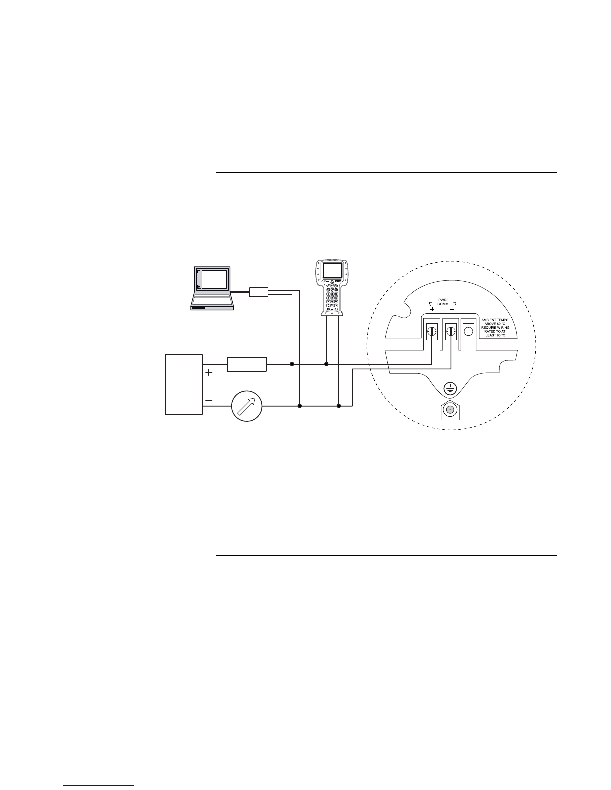
Rosemount 5300 Series
Load Resistance
Power
Supply
375 Field
Communicator
Rosemount 5300 Series
Radar Transmitter
HART modem
RRM
AMS Suite
250
Reference Manual
00809-0100-4530, Rev BA
July 2009
Non-Intrinsically Safe
Output
Figure 4-5. Wiring diagram for
non-intrinsically safe
installations (HART).
With non-intrinsically safe power supply in non-hazardous installations or
Explosion-proof/Flameproof installations, wire the transmitter as shown in
Figure 4-5.
NOTE!
Make sure that the power supply is off when connecting the transmitter.
4-6
For HART communication a minimum load resistance o f 250 within the loop
is required. For maximum load resistance. See Figure 4-1
(Explosion/Flameproof) and Figure 4-2 (Non-hazardous installations).
For Explosion-proof/Flameproof applications the resistance betwee n the
negative terminal on the transmitter and the power supply must not exceed
435 Ohm.
NOTE!
For Explosion-proof/Flameproof installations, make sure the transmitter is
grounded to the internal ground terminal inside the terminal compartment in
accordance with national and local electrical codes.
Page 65

Reference Manual
Load Resistance
Power
Supply
375 Field
Communicator
Rosemount 5300 Series
Radar Transmitter
HART modem
RRM
AMS Suite
250
Approved IS Barrier
00809-0100-4530, Rev BA
July 2009
Rosemount 5300 Series
Intrinsically Safe Output For intrinsically safe installations wire the transmitter as shown in Figure 4-6.
NOTE!
Make sure the instruments in the loop are installed in accordance with
intrinsically safe field wiring practices and System Control Drawings when
applicable.
Figure 4-6. Wiring diagram for
intrinsically safe installations
(HART).
For HART communication, a minimum load resistance of 250 within the
loop is required. For maximum load resistance see Figure 4-3.
The power supply voltage ranges from 16 Vdc to 30 Vdc.
IS parameters
(1)
Ui=30 V.
Ii=130 mA.
Pi=1 W.
Ci=7.26 nF.
Li=0.
(1) See Section B: Product Certifications for more information.
4-7
Page 66

Reference Manual
00809-0100-4530, Rev BA
Rosemount 5300 Series
July 2009
FOUNDATION FIELDBUS
Power Requirements Terminals in the transmitter housing provide connections for signal cables.
The Rosemount 5300 transmitter is powered over F
standard fielbus power supplies. The transmitter operates with the following
power supplies:
Approval Type Power Supply (Vdc)
IS 9 - 30
Explosion-Proof/Flameproof 16 - 32
None 9 - 32
FISCO; IS 9 - 17.5
OUNDATION Fieldbus with
Connecting the
Transmitter
To connect the transmitter:
1. Make sure the power supply is switched off.
2. Remove the terminal block cover.
3. Pull the cable through the cable gland/conduit. Install wiring with a drip
loop. The bottom of the loop must be lower than the cable/conduit entry.
4. Connect wires according to Figure 4-9 for non-intrinsically safe power
supplies, and according to Figure 4- 10 for intrinsically safe power
supplies.
5. Use the enclosed metal plug to seal any unused port.
6. Mount the cover and tighten the cable gland making sure the cover is
secure to meet explosion-proof requirements.
7. For ATEX, IECEx and NEPSI installations, lock the cover with the
Locking Screw .
8. Connect the power supply.
NOTE!
Use PTFE tape or other sealant at the NPT threads in the Cable Entries.
4-8
Page 67

Reference Manual
1
1
3
2
5
4
00809-0100-4530, Rev BA
July 2009
Figure 4-7. Terminal
compartment and external
ground screw.
Rosemount 5300 Series
Cable entries.
Internal Ground screw.
Terminals for signal and power supply.
Locking screw.
External Ground screw
Grounding - Foundation Fieldbus
Signal wiring of the fieldbus segment cannot be groun ded. Grounding out one
of the signal wires will shut down the entire fieldbus segment.
Shield Wire Ground
To protect the fieldbus segment from noise, grounding techniques for shield
wire usually require a single grounding point for shield wire to avoid cr eating a
ground loop. The ground point is typically at the power supply.
4-9
Page 68

Rosemount 5300 Series
Signal
Wiring
Power
Supply
F
OUNDATION
Fieldbus
Configuration
Tool
Terminators
6234 ft (1900 m) maximum
(depending upon cable
characteristics)
Integrated Power
Conditioner
and Filter
(Trunk)
(Spur)
(Spur)
(The power supply,
filter, first
terminator, and
configuration tool
are typically located
in the control room.)
Fieldbus
Segment
Fieldbus
devices on
segment
*Intrinsically safe installations
may allow fewer devices per I.S.
barrier due to current
limitations.
Configuration with Rosemount Radar Master
(in a fieldbus system hooked up on Fieldbus
segment).
Connecting Fieldbus Devices
Figure 4-8. Rosemount 5300
Radar Transmitter field wiring.
Reference Manual
00809-0100-4530, Rev BA
July 2009
4-10
Page 69

Reference Manual
Power
supply
375 Field Communicator
Rosemount 5300 Series
Radar Transmitter
PC
U
max
=250 V
Fieldbus Modem
00809-0100-4530, Rev BA
July 2009
Rosemount 5300 Series
Non-Intrinsically Safe
Output
Figure 4-9. Wiring for
non-intrinsically safe power
supply (Foundation Fieldbus).
With non-intrinsically safe power supply in Non-hazardous installations or
Explosion-proof/Flameproof installations, wire the transmitter as shown in
Figure 4-9.
NOTE!
Make sure that the power supply is off when connecting the transmitter.
NOTE!
For Explosion Proof/Flameproof installations, make sure the transmitter is
grounded to the internal ground terminal inside the terminal compartment in
accordance with national and local electrical codes.
4-11
Page 70

Reference Manual
Power
supply
Rosemount 5300 Series
Radar Transmitter
Approved IS Barrier
375 Field Communicator
PC
Fieldbus Modem
00809-0100-4530, Rev BA
Rosemount 5300 Series
July 2009
Intrinsically Safe Output When your power supply is intrinsically safe, wire the transmitter as shown in
Figure 4-10.
NOTE!
Make sure the instruments in the loop are installed in accordance with
intrinsically safe field wiring practices.
Figure 4-10. Wiring diagram for
intrinsically safe power supply
(Foundation Fieldbus).
4-12
IS parameters
(1)
Ui=30 V.
Ii=300 mA.
Pi=1.5 W (ATEX), 1.3 W (FM)
Ci=7.26 nF.
Li=0.
FISCO IS parameters
Ui=17.5 V.
Ii=380 mA.
Pi=5.32 W.
Ci=0.
Li=0.
(1) See Section B: Product Certifications for more information.
Page 71

Reference Manual
Ch. 3
Ch. 2
Ch. 1
Each Tri-Loop
Channel
recieves power
from Control
Room
Channel 1 must
be powered for
the Tri-Loop to
operate
Device recieves
power from
Control Room
R
L
250
HART Burst Command 3/
Analog Output
Intrinsically Safe Barrier
DIN Rail Mounted
HART Tri-Loop
Control Room
Burst Input
to Tri-Loop
Rosemount 5300 Series
Radar Transmitter
00809-0100-4530, Rev BA
July 2009
OPTIONAL DEVICES
Rosemount 5300 Series
Tri-Loop HART to analog
converter
Figure 4-11. Wiring diagram for
HART Tri-Loop.
The Rosemount 5300 transmitter outputs a HART signal with four process
variables. By using the Model 333 HART Tri-Loop, up to three additional
analog 4-20 mA outputs are provided.
Configure Channels 1, 2, and 3 to reflect the units as well as Upper Range
Values and Lower Range Values for your secondary, tertiary and fourth
variables (variable assignment is configured in the Rosemount 5300). It is
also possible to enable or disable a channel from this menu. See “Tri-Loop
HART to Analog Converter“ on page 5-45 for further information on how to
install a Tri-Loop.
4-13
Page 72

Rosemount 5300 Series
Power supply
Rosemount 5300 Series
Radar Transmitter
Model 751 Field
Signal Indicator
751 Field Signal Indicator
Figure 4-12. Wiring diagram for
a Rosemount 5300 transmitter
with 751 Field Signal Indicator.
Reference Manual
00809-0100-4530, Rev BA
July 2009
4-14
Page 73

Reference Manual
00809-0100-4530, Rev BA
July 2009
Rosemount 5300 Series
Section 5 Configuration
Safety messages . . . . . . . . . . . . . . . . . . . . . . . . . . . . . . . . . page 5-1
Overview . . . . . . . . . . . . . . . . . . . . . . . . . . . . . . . . . . . . . . . page 5-2
Basic Configuration Parameters . . . . . . . . . . . . . . . . . . . . page 5-4
Basic Configuration Using a 375 Field Communicator . . page 5-11
Basic Configuration Using Rosemount Radar Master . . page 5-13
Basic Configuration Using AMS Suite (HART) . . . . . . . .page 5-30
Basic Configuration Using DeltaV . . . . . . . . . . . . . . . . . . page 5-31
F
OUNDATION Fieldbus Overview . . . . . . . . . . . . . . . . . . . . . page 5-36
Configure the AI Block . . . . . . . . . . . . . . . . . . . . . . . . . . . . page 5-39
Tri-Loop HART to Analog Converter . . . . . . . . . . . . . . . . . page 5-45
HART Multi-drop Configuration . . . . . . . . . . . . . . . . . . . . . page 5-47
SAFETY MESSAGES Procedures and instructions in this section may require special precautions to
ensure the safety of the personnel performing the operations. Information that
raises potential safety issues is indicated by a warning symbol ( ). Refer to
the safety messages listed at the beginning of each section before performing
an operation preceded by this symbol.
Explosions could result in death or serious injury:
Verify that the operating environment of the gauge is consistent with the appropriate
hazardous locations certifications.
®
Before connecting a HART
sure the instruments in the loop are installed in accordance with intrinsically safe or
non-incendive field wiring practices.
Do not remove the gauge cover in explosive atmospheres when the circuit
is alive.
Failure to follow safe installation and servicing guidelines could result in death or
serious injury:
Make sure only qualified personnel perform the installation.
Use the equipment only as specified in this manual. Failure to do so may impair the
protection provided by the equipment.
Do not perform any service other than those contained in this manual unless you are
qualified.
-based communicator in an explosive atmosphere, make
www.rosemount.com
Page 74

Reference Manual
00809-0100-4530, Rev BA
Rosemount 5300 Series
July 2009
OVERVIEW The configuration of a Rosemount 5300 transmitter is normally a simple and
straight-forward task. The complete configuration of a Rosemount 5300
transmitter includes Basic Configuration, Echo Tuning and Advanced
Configuration. This section describes Basic Configuration.
If the transmitter is pre-configured at the factory according to the ordering
specifications in the Configuration Data Sheet, no further Basic Configuration
is required unless tank conditions have changed. The Rosemount 53 00
Series supports a set of advanced configuration op tions as well, which can be
used to handle special tank conditions and applications.
Basic Configuration The Basic Configuration includes parameters for a standard configuration
which is sufficient in most cases. The Basic Configuration comprises the
following items:
• Measurement Units
• Tank Configuration
- Tank Geometry
- Environment
- Volume
• Analog Output
Echo Tuning Amplitude thresholds can be adjusted in order to handle special situations
when, for example, objects in the tank cause disturbing echoes that are
stronger than the surface echo. A useful function is the so called Amplitude
Threshold Curve (ATC) which lets you filter out single disturbing echoes. See
Section 7: Service and Troubleshooting, and Appendix C: Advanced
Configuration for more information.
LCD Configuration It is possible to specify the variables to be presented on the Display Panel.
See also Section 6: Operation.
Advanced Configuration For some applications, further device specific configuration is needed in
addition to the Basic Configuration. This may be due to product properties or
tank shape. See Appendix C: Advanced Configuration for more information.
Configuration Tools There are several tools available for the configuration of a Rosemo unt 5300
transmitter:
• Rosemount Radar Master (RRM). Note that RRM is recommended for
advanced configuration features.
See “Basic Configuration Using Rosemount Radar Master” on
page 5-13 for information on how to use RRM for configuration of the
5300 Series
• Rosemount 375 Field Communicator.
See “Basic Configuration Using a 375 Field Communi cato r” on
page 5-11 for the Field Communicator Menu Tree
• AMS Suite software (for HART). See “Basic Configuratio n Using AMS
Suite (HART)” on page 5-30
• DeltaV (only for Foundation Fieldbus). See “Basic Configuration Using
DeltaV” on page 5-31
• Other tools that support Electronic Device Description Language
(EDDL) functionality
5-2
Page 75

Reference Manual
00809-0100-4530, Rev BA
July 2009
Rosemount 5300 Series
RRM is a user-friendly, Windows® based software package including
waveform plots, off-line/on-line configuration Wizard, logging, and extensive
on-line help.
To communicate with the transmitter using RRM, a HART modem (part
number 03300-7004-0001 or 03300-7004-0002) or a F
modem (part number 03095-5108-0001 for PCMCIA) is required. For
OUNDATION Fieldbus communication you will also need the National
F
Instruments Communication Manager software (see “Installing the RRM
Software for FOUNDATION Fieldbus” on page 5-16).
OUNDATION Fieldbus
5-3
Page 76

Rosemount 5300 Series
Tank Height
Hold Off/
Upper Null Zone
Product Level
Upper Reference Point
Lower Reference Point
Interface
Level
Probe
Length
NPT BSP (G) Flange
Upper Reference Point
Adapter
Tri-Clamp
Reference Manual
00809-0100-4530, Rev BA
July 2009
BASIC CONFIGURATION
PARAMETERS
This section describes basic configuration parameters for a Rosemo unt 530 0
transmitter. Basic configuration is only needed for the 5300 Series
transmitters which are not pre-configured at the factory. Factory configuration
is normally specified in the Configuration Data Sheet.
Measurement Units Measurement units can be specified for present ation of L evel/Interface Le vel,
Level Rate, Volume, and Temperature values.
Tank and Probe
Geometry
Figure 5-1. Tank Geometry
The basic transmitter configuration includes setting the tank geo metry
parameters.
Figure 5-2. Upper Reference
Point
5-4
For the different tank co nnections the Up per Reference Point is loca ted at the
underside of the threaded adapter or at the underside of the welde d flange, as
illustrated in Figure 5-2:
Page 77

Reference Manual
00809-0100-4530, Rev BA
July 2009
Rosemount 5300 Series
Tank Height
The Tank Height is defined as the distance from the Upper Reference Point to
the Lower Reference Point. The transmitter measures the distance to the
product surface and subtracts this value from the Tank Height to determine
the product level. The Lower Reference Point can be set to any position in the
tank simply by adjusting the Tank Height.
Mounting Type
Enter the type of mounting for the device. This configuration optimizes the
device for the respective mounting type.
• Unknown – default factory setting for mounting type, and can also be
used if the mounting type is unknown
• Pipe/Chamber – select this option if the device is mounted on a
chamber/bridle or in a pipe. When selecting this alternative enter the
corresponding Inner Diameter as well
• Nozzle – select this if the device is installed on a nozzle. When
selecting this alternative, configure the Inner Diameter and the Nozzle
Height as well
• Direct/Bracket – when the device is mounted directly on the tank roof
with no traditional nozzle, this is the alternative to use. With this
selection no inner diameter or height is required, thus those selections
are disabled
Inner Diameter
Using with pipe, chamber - and nozzle installations.
Nozzle Height
For nozzle installations.
Probe Length
The probe length is the distance betwee n the Upper Reference Point and the
end of the probe. If a weight is used at the end of the probe, it should not be
included.
For Flexible Single Lead probes anchored with clamps, the probe length
should be configured as the distance between the underside of the flange and
the upper clamp (see “Anchoring” on page 3-22).
This parameter is pre-configured at the factory. It must be changed if the
probe is shortened.
Probe Type
The transmitter is designed to optimize measurement performance for each
probe type.
This parameter is pre-configured at the factory. This value needs to be
changed if the probe type is changed.
5-5
Page 78

Rosemount 5300 Series
Hold Off/Upper Null Zone
This parameter should only be chang ed if there are measuremen t problems in
the upper part of the tank. Such problems may occur if there are disturbing
objects, such as a narrow nozzle with rough walls, close to the probe. By
adjusting the Hold Off/Upper Null Zone, the measuring range is reduced. See
“Handling of Disturbances from Nozzle” on page C-4 for further information.
Tank Environment Measurement Mode
Normally, the Measurement Mode does not need to be changed. The
transmitter is pre-configured according to the specified model:
Table 5-1. List of Measurement
Modes which can be used for
different 5300 models
Model Measurement Mode
5301
5302
5303
• Liquid Product Level
• Interface Level with Submerged probe
• Liquid Product Level
• Product Level and Interface Level
• Interface Level with Submerged probe
• Solid Product Level
• Solid Product Level
Reference Manual
00809-0100-4530, Rev BA
July 2009
(1)
(1)
(1)
(1) Default setting
Submerged is used for applications where the probe is fully submerged in
liquid. In this mode, the transmitter ignores the upper product level. See
“Interface Measurements with Fully Submerged Probes” on page 7-15” for
more information.
NOTE!
Only use Submerged for applications where the interface is measured with a
fully submerged probe.
Rapid Level Changes
Optimize the transmitter for measurement conditions where the level changes
quickly due to filling and emptying of the tank. As a default standard, a
Rosemount 5300 transmitter is able to track level changes of up to
1.5 in./s (40 mm/s). When the Rapid Level Changes check box is marked, the
transmitter can track level changes of up to 8 in./s (200 mm/s).
The Rapid Level Changes check-box should not be used in normal conditions
when the product surface moves slowly.
Dielectric Constant
For interface measurements, the dielectric constant of the upper product is
essential to obtain good accuracy. See “Interface” on page 2-12 for further
information on dielectric constants. If the dielectric constant of the lower
product is significantly smaller than the dielectric constan t of water, you may
need to make special adjustments, see Appendix C: Advanced Configuration
for further information.
5-6
For level measurements, the Upper Product Dielectric parameter
corresponds to the actual dielectric constant of the product in the tank.
Page 79

Reference Manual
Actual tank bottom may look like this.
Using only 3 strapping points results in a level-to-volume profile
that is more angular than the actual shape.
Using 10-15 of the points at the bottom of the tank yields a
level-to-volume profile that is similar to the actual tank bottom.
00809-0100-4530, Rev BA
July 2009
Rosemount 5300 Series
Normally, this parameter does not need to be changed even if the actual
dielectric constant of the product deviates from the Upper Product Dielectric
parameter value. However, for some products, measurement performance
can be optimized by setting the proper product dielectric constant.
Volume Configuration For volume calculations, you can choose one of the standard tank shapes or
the strapping option. Choose None if volume calculation is not used. For the
standard tanks, a Volume Offset parameter can be specified which can be
used for a non-zero volume that corresponds to the zero level. This may be
useful, for example, if the user want s to includ e the product volume below the
zero level.
Tank Type
You can choose one of the following options:
• Strap table
• Vertical Cylinder
• Horizontal Cylinder
• Vertical Bullet
• Horizontal Bullet
• Sphere
•None
Figure 5-3. Strapping points
Strapping Table
Use a strapping table if a standard tank type does not provide sufficient
accuracy . Use most o f the strapp ing point s in region s where th e ta nk shape is
non-linear. A maximum of 20 points can be added to the strapping table.
5-7
Page 80

Rosemount 5300 Series
Diameter
Height
Diameter
Height
Diameter
Height
Diameter
Height
Diameter
Standard Tank Shapes
Figure 5-4. Standard tank
shapes
Reference Manual
00809-0100-4530, Rev BA
July 2009
Vertical Cylinder
Vertical Cylinder t anks are sp ecified by
Diameter, Height, and Volume Offset.
Horizontal Cylinder
Horizontal Cylinders are specified by
Diameter, Height, and Volume Offset.
Vertical Bullet
Vertical Bullet tanks are specified by
Diameter, Height and Volume Offset.
The volume calculation model for this
tank type assumes that the radius of
the bullet end is equal to the
Diameter/2.
Horizontal Bullet
Horizontal Bullets are specified by
Diameter, Height, and Volume Offset.
The volume calculation model for this
tank type assumes that the radius of
the bullet end is equal to the
Diameter/2.
Sphere
5-8
Spherical tanks are specified by
Diameter and Volume Offset.
Page 81

Reference Manual
20 mA Upper Range Value (URV) = 100%
Upper Transition Zone
Product Level
Lower Transition Zone
4 mA Lower Range Value
(LRV) = 0%
Upper Reference Point
Range 0-100%
Lower Reference Point (Level=0)
00809-0100-4530, Rev BA
July 2009
Rosemount 5300 Series
Analog Output (HART) The Output Source (Primary Value), Range Values and Alarm Mode are
specified for the analog output.
Figure 5-5. Example of Range
Value settings
Output Source/Primary Variable
Specify the source to control the analog output. Typically, the Primary Value is
configured to be the Product Level.
Upper/Lower Range Value
Enter the range values that correspond to the analog output values
4 and 20 mA. It is recommended that the 4 mA and 20 mA values are set
outside the Transition Zones. See “Transition Zones” on page 2-10 for more
information.
If a measured value goes beyond the measurement range, the transmitter
enters saturation mode (limit alarm is disabled) or alarm mode depending on
the current configuration.
Also make sure that the 20 mA value is below the Upper Null Zone (UNZ).
(This parameter may be used if there are measurement problems in the upper
part of the tank, see “Handling of Disturbances from Nozzle” on page C-4).
The UNZ is equal to zero in the default configuration.
5-9
Page 82

Rosemount 5300 Series
Alarm Mode
The Alarm mode specifies the analog output sta t e when th er e is a failu re or a
measurement error:
High: the output current is set to the High Alarm Limit.
Low: the output current is set to the Low Alarm Limit.
Freeze Current: the output current is set to the last valid value at the time
when the error occurs.
Default settings for alarm mode:
• Measurement errors: Output current=High.
• Measured value out of range: transmitter enters saturation mo de (if
Table 5-2. Analog Output:
Standard Alarm Values vs.
Saturation Values
Level 4–20 mA Saturation Values 4–20 mA Alarm Value
Reference Manual
00809-0100-4530, Rev BA
July 2009
Limit Alarm is disabled).
Low 3.9 mA 3.75 mA
High 20.8 mA 21.75 mA
Table 5-3. Analog Output:
NAMUR-Compliant Alarm
Values vs. Saturation Values
Level 4–20 mA Saturation Values 4–20 mA Alarm Value
Low 3.8 mA 3.6 mA
High 20.5 mA 22.5 mA
5-10
Page 83

Reference Manual
Function Key
Navigation Keys
Alphanumeric Keys
Backlight adjustment key
Tab Key
Enter Key
00809-0100-4530, Rev BA
July 2009
Rosemount 5300 Series
BASIC CONFIGURATION
USING A 375 FIELD
COMMUNICATOR
Figure 5-6. The 375 Field
Communicator.
This section describes how to configure the 5300 transmitter by using a 375
Field Communicator.
The menu tree with the various configuration parame ters is shown in Figure
5-7 on page 5-12. Section “Basic Configuration Parameters” on page 5-4
presents a description of the basic configuration parameters.
For information on all the capabilities, refer to the 375 Field Communicator
Product Manual (Document No. 00809-0100-4276).
1. Check that the desired Measurement Units are selected.
2. Open the Process Variable menu and select Primary Variable. HART
command: [1,1]. Select the desired parameter.
3. Open the Basic Setup menu. HART command: [2, 1]. This menu
includes Probe, Tank Geometry, Environment, Volume, and Analog
Output settings.
4. Select Finish, Device Specific Setup to see if there is any additional
configuration that needs to be done.
5. Restart the transmitter. HART command: [3, 2, 1, 1].
See also “Guided Setup” on page 5-19 for further information on configuration
of the Rosemount 5300 transmitter.
5-11
Page 84

Rosemount 5300 Series
Process Variables
1 Process Variabl es
2Setup
3 Diagnostics
4 Primary Variable
Value
5 Analog Out
6 Distance
7 Signal Strength
1 Primary Variable
22nd
33rd
44th
5All variables
6 Signal Quality
Metrics
7 Identification
1Basic Setup
2Device
3Tank
4 Analog output
5 Echo Tuning
6 Echo Curve
7 Advanced
8Calibration
1 Diagnostics
2 Tools
1Variable Mapping
2Probe
3 Geometry
4 Environment
5Volume
6 Analog output
7Finish
1Identification
2 Variable Mapping
3LCD
4 Communication
5Alarm/Sat. Limits
1Identification
2 Variable Mapping
3LCD
4 Communication
5Alarm/Sat. Limits
1Probe
2 Geometry
3 Environment
4Volume
1Analog Out
2Alarm/Sat. Limits
1Echo Peaks
2 Thresholds
1Echo Curve
1Near Zone
2 Probe End Projection
3 Dynamic Vapor
Compensation
4 Signal Quality Metrics
5 Echo Tracking
Setup
Diagnostics/Tools
1Primary Variable
22nd
33rd
44th
5 HART Digital Units
6 Damping Value
7 Device Status
1Probe Type
2 Probe Length
3 Upper Null Zone
4Drawing
1Tank Height
2 Mounting Type
3 Inner Diameter
4 Nozzle Height
5 Drawing
1Measurement Mode
2 Product Diel. Range
3 Upper Prod. Dielectr.
4 Process Conditions
5 Drawing
1Calculation Method
2 Tank Diameter
3 Tank Length
4 Volume Offset
5 Strapping Table
6Drawing
1Primary Variable
2 Range Values
3 Alarm Mode
4 Sensor Limits
5 Alarm Mode Definit.
1Finish Setup
2 Device Specific Setup
3 After Setup Restart
F/W
4 Restart Device
1Analog Output
Figure 5-7. HART Communicator Menu Tree corresponding to Device Revision 3.
Reference Manual
00809-0100-4530, Rev BA
July 2009
5-12
Page 85

Reference Manual
00809-0100-4530, Rev BA
July 2009
Rosemount 5300 Series
BASIC CONFIGURATION
USING ROSEMOUNT
RADAR MASTER
The Rosemount Radar Master (RRM) is a user-friendly software tool that
allows the user to configure the Rosemount 5300 Series transmitter. Choose
either of the following methods to configure a Rosemount 5300 Series
transmitter with RRM:
• Guided Setup if you are unfamiliar with the 5300 transmitter (see
page 5-19).
• Setup functions if you are already familiar with the configuration
process or for changes to the current settings (page 5-18).
System Requirements Hardware
Processor (minimum/recommended): Pentium 200 MHz/1 GHz
Memory (minimum/recommended): 64/128 MB RAM
COM Port: 1 serial COM port or 1 USB port
Graphical Card (minimum/recommended):
screen resolution 800 x 600/1024 x 768
Hard drive space: 100 MB
Software
Operating Systems supported:
Windows 2000 - Service Pack 3
Windows XP - Service Pack 2
Help In RRM Help is accessed by selecting the Contents option from the Help menu. Help
is also available from a Help button in most windows.
5-13
Page 86

Rosemount 5300 Series
RRM communicates
with the transmitter
No communication
with the transmitter
Installing the RRM
software for HART
communication
To install the Rosemount Ra da r Ma st er :
1. Insert the installation CD into your CD-ROM drive.
2. If the installation program is not automatically started, choose Run from
the Windows Start bar.
3. Type D:\RRM\Setup.exe, where D is the CD-ROM drive.
4. Follow the instructions on the screen.
5. Make sure that HART is chosen as default protocol.
6. For Windows 2000/XP set COM Port Buffers to 1, see page 5-15.
Reference Manual
00809-0100-4530, Rev BA
July 2009
Getting Started
1. From the Start menu click Programs>Rosemount>Rosemount Radar
Master or click the RRM icon in the Windows workspace.
2. If the Search Device window did not appear automatically, choose menu
option Device>Search.
3. In the Search Device window , choo se communication protocol HAR T, and
click the Start Scan button (click the Advanced button if you want to specify
start and stop address).
Now RRM searches for the transmitter.
4. After a while the Search Device window presents a list of found
transmitters.
5. Select the desired transmitter and press OK to connect. If communication
does not work, check that the correct COM port is connected to the computer
and that the COM port is properly configured, see “Specifying the COM Port”
on page 5-15. You may also check in the Communication Preferences
window that HART communication is enabled.
6. In the RRM Status Bar verify that RRM communicates with the transmitter:
5-14
Page 87

Reference Manual
00809-0100-4530, Rev BA
July 2009
Rosemount 5300 Series
Specifying the COM Port If communication is not established, open the Communication Preferences
window and check that the correct COM Port is selected:
1. From the View menu select Communication Preferences in RRM.
Figure 5-8. Communication
Preferences.
To set the COM port
buffers
2. Select the HART tab.
3. Make sure that HART communication is enabled.
4. Check which COM port the modem is connected to.
5. Choose the COM Port option that matches the actual COM Port on the PC
that the transmitter is connected to.
For Windows 2000/XP the COM port Receive Buffer and Transmit Buffer
need to be set to 1. To set the COM port buffers:
1. In the MS Windows Control Panel open the System option.
2. Choose the Hardware tab and click the Device Manager button.
3. Expand the Ports node in the tree view.
4. Click the right mouse button on the selected COM port and choose
Properties.
5. Select the Port Settings tab and click the Advanced button.
6. Drag the Receive Buffer and Transmit Buffer slides to 1.
7. Click the OK button.
8. Restart the computer.
5-15
Page 88

Rosemount 5300 Series
Installing the RRM
Software for
FOUNDATION Fieldbus
To install the Rosemount Radar Mast er for F OUNDATION Fieldbus
communication:
1. Start by installing the National Instruments Communication Manager
software. See National Instruments manual (Getting started with your
PCMCIA-FBUS and the NI-FBUS™ software) for more information.
2. Insert the RRM installation CD into your CD-ROM drive.
3. If the installation program is not automatically started, choose Run from
the Windows Start bar.
Reference Manual
00809-0100-4530, Rev BA
July 2009
4. Type D:\RRM\Setup.exe where D is the CD-ROM drive.
5. Follow the instructions on the screen.
6. Make sure that F
Getting Started
1. Before starting RRM make sure that appropriate settings are made with
the National Instruments Interface Configuration Utility:
If only Rosemount Radar Master is connected to th e bu s:
Device address=Fixed
Device Type=Link Master Device
Usage=NI-FBUS
If other host systems are connected to the bus:
Device address=Visitor
Device Type=Basic Device
Usage=NI-FBUS
OUNDATION Fieldbus is chosen as default protocol.
5-16
Page 89

Reference Manual
RRM communicates
with the transmitter
No communication
with the transmitter
00809-0100-4530, Rev BA
July 2009
Rosemount 5300 Series
2. Start Rosemount Radar Master (RRM): from the Start menu click
Programs>Rosemount>Rosemount Radar Master or click the RRM icon
in the MS Windows workspace.
3. If the National Instruments Communication Manager server is not running,
click Yes when RRM displays a request for starting the server.
4. If the Search Device window did not appear automatically choose menu
option Device>Search.
5. In the Search Device window choose communication protocol
F
OUNDATION Fieldbus (if not already selected) and click the Start Scan
button (click the Advanced button if you want to spec ify start and stop
dress).
Now RRM searches for the transmitter. After a while RRM shows the
transmitters found on the bus:
Specifying Measurement
Units
6. Select the desired transmitter and click OK to connect.
In the RRM Status Bar verify that RRM communicates with the
transmitter:
Measurement units for data presentation in RRM can be specified when the
RRM program is installed. Units can also be changed as follows:
1. From the View menu, choose the Application Preferences option.
2. Select the Measurement Units tab.
3. Choose the desired units for Length, Level Rate, Volume, and
Temperature.
5-17
Page 90

Rosemount 5300 Series
General
Tank Geometry,
Environment,
Volume
Analog Output
Echo Curve
Advanced
Wizard
Reference Manual
00809-0100-4530, Rev BA
July 2009
Using the Setup
Functions
Figure 5-9. Setup functions in
RRM.
Use the Setup function if you are already familiar with the configuration
process for the Rosemount 5300 Series transmitter or for chang es to the
current settings:
1. Start the RRM software.
2. In the RRM workspace choose the
appropriate icon for the configuration of
transmitter parameters:
• Wizard: the Wizard is a tool that
guides you through the basic
configuration procedure of a
Rosemount 5300 Series
transmitter
• General: configuration of general
settings such as measurement
units and communication
parameters. This window also lets
you configure which LCD variables
to be displayed, see Section 6:
Operation
• Tank: configuration of Tank
Geometry, Tank Environment, and
Volume
• Output: configuration of Analog
Output
• Echo Curve: disturbance echo
handling
• Advanced: advanced
configuration
5-18
Page 91

Reference Manual
Run Wizard
00809-0100-4530, Rev BA
July 2009
Rosemount 5300 Series
Guided Setup The following description shows how to use the RRM Guided Setup. The
corresponding HART commands (375 Field Communicator Fast Key
Sequence) and F
The Guided Setup is useful if you are unfamiliar with the Rosemount 5300
Series transmitter.
1. Start the Guided Setup
Start RRM. It autom atically presents a list of available transmitters. Select
the desired transmitter. Now the transmitter is connected and the Guided
Setup window appears automatically:
OUNDATION Fieldbus parameters are also shown.
2. Start the Configuration Wizard
In the Guided Setup window, click the Run Wizard... button and follow the
instructions.
Now you will be guided through a short transmitter installation procedure.
NOTE!
The Guided Setup is an extended installation guide that includes more than
just the configuration Wizard. It can be disabled by deselecting the Show
Introduction Dialog after Connect check box in the Application Settings
window (see menu option View>Application Preferences).
5-19
Page 92

Rosemount 5300 Series
Device Properties
3. Check the device properties
The first window in the configuration wizard presents general information
stored in the transmitter database such as device model, serial number,
probe type, probe length, communication protocol and device address.
Check that the information complies with the ordering information.
Reference Manual
00809-0100-4530, Rev BA
July 2009
General Information
4. Enter Device Information
HART command: [2, 2, 1].
This window lets the user enter Tag, Message, Descriptor, and Date. The
information is not required for the operation of the transmitter and can be
left out if desired.
5-20
Page 93

Reference Manual
00809-0100-4530, Rev BA
July 2009
Probe
Rosemount 5300 Series
5. Probe settings
HART command: [2, 1, 2].
F
OUNDATION Fieldbus parameters:
TRANSDUCER 1100>PROBE_TYPE
TRANSDUCER 1100>PROBE_LENGTH
TRANSDUCER 1100>GEOM_HOLD_OFF_DIST
Check that the correct Probe Type is chosen. Normally, the Probe Type is
pre-configured at the factory, but if the current configuration does not match
the actual probe, choose the correct Probe Type from the list.
The Rosemount 5300 Series transmitter automatically makes some initial
calibrations based on the chosen Probe Type. The following Probe Types are
available:
• Rigid Twin
• Flexible Twin
• Coaxial, Coaxial HP, Coaxial HTHP
• Rigid Single, Rigid Single HTHP/HP/C, Rigid Single PTFE
• Flexible Single, Flexible Single HTHP/HP/C, Flexible Single PTFE
The Probe Length is the distance from the Upper Reference Point to the end
of the probe, see Figure 5-1. If the probe is anchored to a weight, do not
include the height of the weight. The Probe Length needs to be changed if, for
example, the probe is shortened.
The Hold Off Distance/Upper Null Zone (UNZ) should not be changed
unless there are disturbances at the top of the tank. By increasing the Upper
Null Zone, measurements in this region are avoided. See “Handling of
Disturbances from Nozzle” on page C-4 for more information on how to use
the UNZ. The UNZ is set to zero in the factory configuration.
5-21
Page 94

Rosemount 5300 Series
Geometry
Reference Manual
00809-0100-4530, Rev BA
July 2009
6. Geometry
HART command: [2, 1, 3].
F
OUNDATION Fieldbus parameter:
TRANSDUCER 1100>GEOM_TANK_HEIGHT
TRANSDUCER 1100>MOUNTING_TYPE
TRANSDUCER 1100>PIPE_DIAMETER
TRANSDUCER 1100>NOZZLE_HEIGHT
Tank Height is the distance from the Upper Reference Point to the Lower
Reference Point (see Figure 5-1 on page 5-4 and Figure 5-2 on page 5-4).
The Upper Reference Point is located at the bottom part of the threaded
adapter, or at the underside of the welded flange.
Make sure the Tank Height is as accurate as possible, since a Tank Height
error results in a corresponding Level value offset error.
When specifying the Tank Height, keep in mind that this value is used for all
level and volume measurements performed by the Rosemount 5300 Series
transmitter.
The Tank Height must be set in linear (level) units, such as feet or meters,
regardless of primary variable assignment.
Select the Mounting Type used.
Select Inner Diameter if using pipe, chamber or nozzle.
5-22
Type Nozzle Height if using nozzle.
Page 95

Reference Manual
00809-0100-4530, Rev BA
July 2009
Tank Environment
Rosemount 5300 Series
7. Specify Tank Environment
HART command: [2, 1, 4].
F
OUNDATION Fieldbus parameter:
TRANSDUCER 1100>MEAS_MODE
TRANSDUCER 1100>PRODUCT_DIELEC_RANGE
TRANSDUCER 1100>UPPER_PRODUCT_DC
TRANSDUCER 1100>ENV_ENVIRONMENT
Measurement Mode
Normally, the Measurement Mode does not need to be changed. The
transmitter is pre-configured according to the specified model. See “Basic
Configuration Parameters” on page 5-4 for more information.
Process Conditions
Select the Rapid Level Changes check-box only if the surface is moving
quickly up or down at rates over 1.5 in./s (40 mm/s).
Dielectric Constant/Dielectric Range
The dielectric constant of the product is used for setting the appropriate signal
amplitude thresholds, see Section 7: Service and Troubleshooting for more
information on amplitude threshold settings. Normally, this parameter does
not need to be changed for level measurements. However, for some products,
measurement performance can be optimized by setting the proper product
dielectric constant.
For Interface Level measurements, the dielectric constant of the upper
product is essential for calculating interface level and the upper product
thickness. By default, the Upper Product Dielectric parameter is about 2.
Set the Upper Product Dielectric Constant to a value that corresponds to
the current product.
5-23
Page 96

Rosemount 5300 Series
Rosemount Radar Master (RRM) includes tools to estimate the dielectric
constant of the current product:
•The Dielectric Chart lists the dielectric constant of a large number of
•The Dielectric Calculator lets you calculate the dielectric constant
Reference Manual
00809-0100-4530, Rev BA
July 2009
products. The Dielectric Chart can be opened with one of the following
methods:
- Choose the View>Dielectric Constant Chart menu option
- Click the Dielectric Chart button in the Configuration Wizard -
Environment window
- Choose the Setup>Tank menu option and click the Dielectric Chart
button in the Tank/Environment window
of the Upper Product based on the following input:
- actual upper product thickness,
- the dielectric constant value stored in the transmitter, and
- the upper product thickness presented by the transmitter.
The Dielectric Calculator is available via the Dielectric Calculator
button in the Configuration Wizard - Environment window or the
Tank/Environment window.
5-24
Page 97

Reference Manual
00809-0100-4530, Rev BA
July 2009
Volume
Rosemount 5300 Series
8. Choose Volume Calculation Method
HART command: [2, 1, 5].
F
OUNDATION Fieldbus parameters:
Calculation method:
TRANSDUCER 1300>VOL_VOLUME_CALC_METHOD
Tank Diameter:
TRANSDUCER 1300>VOL_IDEAL_DIAMETER
Tank Length:
TRANSDUCER 1300>VOL_IDEAL_LENGTH
Volume Offset:
TRANSDUCER 1300>VOL_VOLUME_OFFSET
To use volume calculation, choose a pre-defined calculation method based on
the tank shape that best corresponds to the actual tank. See “Volume
Configuration” on page 5-7.
Use the Strapping Table option if the actual tank does not match any of the
available options for pre-defined tanks, or if higher calculation accuracy is
desired.
Choose None if volume calculation is not desired at all.
The following standard tank shapes are available:
• Vertical Cylinder
• Horizontal Cylinder
• Vertical Bullet
• Horizontal Bullet
• Sphere
•None
The following parameters must be entered for a standard tank shape:
• Tank diameter
• Tank height/length (not for spherical tanks)
• Volume Offset: use this parameter if you do not want zero volume and
zero level to match (for example if you want to include a volume below
the zero level)
5-25
Page 98

Rosemount 5300 Series
Analog Output (HART)
9. Configure the Analog Output
HART command: [2,1, 6].
Reference Manual
00809-0100-4530, Rev BA
July 2009
Finish Configuration
Wizard
Analog Output is not available for F
Typically, the Primary Variable (PV) is configured to be Product Level,
Interface Level, or Volume. Other variables like Product Distance, Interface
Distance, Upper Product Thickness, etc. are available as well.
Specify the analog output range by setting the Lower Range Value (4 mA)
and the Upper Range Value (20 mA) to the desired values.
The Alarm Mode specifies the output state when a measurement error occurs.
See also “Analog Output (HART)” on page 5-9 for information on Analog
Output configuration.
OUNDATION Fieldbus.
5-26
10. Finish the Configuration Wizard
This is the last window in the Configuration Wizard concluding the basic
configuration. The current configuration can be changed at any time by using
the Setup windows (General, Tank, Output etc., see “Using the Setup
Functions” on page 5-18).
The Setup windows contain further options not available in the configuration
wizard.
Click the Finish button and continue with the next step in the Guided Setup.
Page 99

Reference Manual
00809-0100-4530, Rev BA
July 2009
Device Specific
Configuration
Rosemount 5300 Series
11. Click the Device specific setup button
12. This window will show if any additional configuration is needed. Proceed
to step 13 if no configuration is needed.
Trim Near Zone is described further in “Handling of Disturbances from
Nozzle” on page C-4.
Probe End Projection is described further in “Probe End Projection” on
page C-10.
Vapor Compensa tion is described further in “Dielectric Constant Settings” on
page C-14.
Choose the Tank Material if recommended.
5-27
Page 100

Rosemount 5300 Series
Restart the Transmitter
13. Restart the transmitter
When the transmitter is configured, it should be rest arted to make sure that all
configuration changes are properly activated and the transmitter performs as
expected. It may take up to 60 seconds after the rest art button is pressed until
measurement values are updated.
Reference Manual
00809-0100-4530, Rev BA
July 2009
View Measured Values
Backup
14. Step three in the Guided Setup lets you view measurement values in order
to verify that the transmitter works correctly. If the measured values seem
incorrect, configuration settings may need to be adjusted.
5-28
15. When configuration is finished, it is recommended that the configuration is
saved to a backup file.
 Loading...