

Page 1
Rosemount™ 499AOZ
Dissolved Ozone Sensor
Quick Start Guide
00825-0100-3492, Rev AB
November 2019
Page 2

Quick Start Guide November 2019
Safety information
CAUTION
Sensor/process application compatibility
The wetted sensor materials may not be compatible with process composition and operating
conditions.
Application compatibility is entirely the operator's responsibility.
CAUTION
Equipment damage
Do not exceed pressure and temperature specifications
Pressure: 65 psig (549 kPa abs) max.
Temperature: 32 to 122 °F (0 to 50 °C)
WARNING
Physical access
Unauthorized personnel may potentially cause significant damage to and/or misconfiguration of end
users’ equipment. This could be intentional or unintentional and needs to be protected against.
Physical security is an important part of any security program and fundamental to protecting your
system. Restrict physical access by unauthorized personnel to protect end users’ assets. This is true for
all systems used within the facility.
Contents
First steps.....................................................................................................................................3
Install........................................................................................................................................... 6
Wire........................................................................................................................................... 10
Calibrate.................................................................................................................................... 15
Maintenance.............................................................................................................................. 17
Accessories................................................................................................................................ 20
2 Emerson.com/Rosemount
Page 3
November 2019 Quick Start Guide
1 First steps
1.1 Unpack and inspect
Procedure
1. Inspect the shipping container. If it is damaged, contact the shipper
immediately for instructions.
2. If there is no apparent damage, unpack the container. Be sure all
items shown on the packing list are present. If items are missing,
notify Emerson immediately.
1.2 Product description
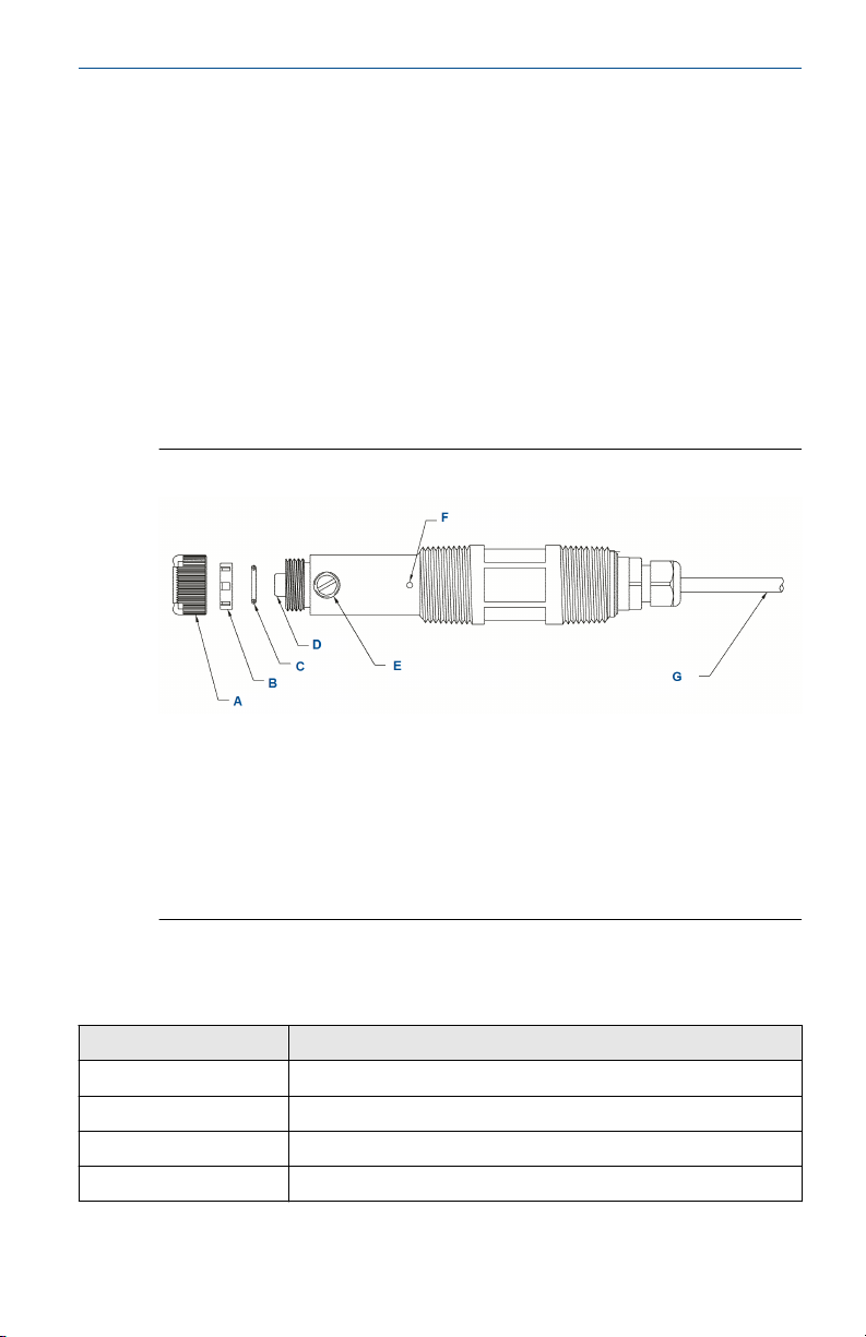
Figure 1-1: Rosemount 499AOZ Sensor Parts
A. Membrane retainer
B. Membrane assembly
C. O-ring
D. Cathode
E. Electrolyte fill plug (wrap with pipe tape)
F. Pressure equalizing port
G. Sensor cable (integral cable shown)
1.3
Table 1-1: Sensor Specifications
Physical characteristics Specifications
Range 0 to 3 ppm (mg/L) as O
Pressure 0 to 65 psig (101 to 549 kPa abs)
Temperature (operating) 32 to 122 °F (0 to 50 °C)
Process connection 1-in. male national pipe thread (MNPT)
Quick Start Guide 3
Specifications
3
Page 4

Quick Start Guide November 2019
Table 1-1: Sensor Specifications (continued)
Physical characteristics Specifications
Wetted parts Polysulfone, Viton®, Teflon®, and silicone
Cathode Gold (not normally wetted)
Accuracy Accuracy depends on the accuracy of the chemical test used to
Linearity ±5% of reading or ±3 ppb (whichever is greater) at 77 °F (25 °C)
Repeatability ±2% of reading at constant temperature
Response time 30< 20 sec to 90% of final reading at 77 °F (25 °C)
Membrane permeability
connection
Electrolyte volume 0.8 oz. (25 mL), approximately
Electrolyte life 3 months (approximately); for best results, replace electrolyte
Cable length See Ordering information table in the Product Data Sheet for cable
Cable length (maximum) 300 ft. (91 m), up to 100 ft. (30.5 m) is standard.
Sample flow Flow through: 1 to 5 gpm (3.8 to 19 L/min)
calibrate the sensor.
Defined between 32 and 122 °F (0 and 50 °C)
monthly.
length options.
Open channel: 1 ft./sec (0.3 m/sec)
Low flow cell: 2 to 5 gph (7.6 to 19 L/hr)
Weight/shipping
(1)
weight
1 lb./3 lb. (0.5 kg/1.5 kg)
(1) Weights and shipping weights are rounded up to the nearest whole pound or 0.5 kg.
Table 1-2: Other Specifications
Type PN Wetted
materials
2-in. tee 915240-03 PVC and Buna
N; body is
schedule 80
PVC
Polycarbonate/
Low flow
(1)
cell
915240-04 1-in. NFPT
915240-05 1½-in. NFPT
24091-00 and
24091-01
polyester,
316 stainless
steel, and
silicone
4 Emerson.com/Rosemount
Process
connection
Maximum
temperature
Maximum
pressure
¾-in. NFPT 120 °F (49 °C) 60 psig (515
kPa abs)
Compression
fitting for
158 °F (70 °C) 90 psig
(722 kPa abs)
¼-in. O.D.
tubing or
¼-in. female
national pipe
thread (FNPT)
Page 5

November 2019 Quick Start Guide
Table 1-2: Other Specifications (continued)
Type PN Wetted
Valved
rotameter
(1) Temperature and pressure specifications for the low flow cell exceed the temperature and
pressure specifications for the sensor.
9390004 for
use with low
flow cell
Flow: 0.5 to 5
gph (1.4 to 19
L/hr)
materials
Acrylic, 316
stainless
steel, and
Viton
Process
connection
¼-in. NFPT
(316 stainless
steel)
Maximum
temperature
150 °F (65 °C) 100 psig (858
Maximum
pressure
kPa abs)
Quick Start Guide 5
Page 6
Quick Start Guide November 2019
2 Install
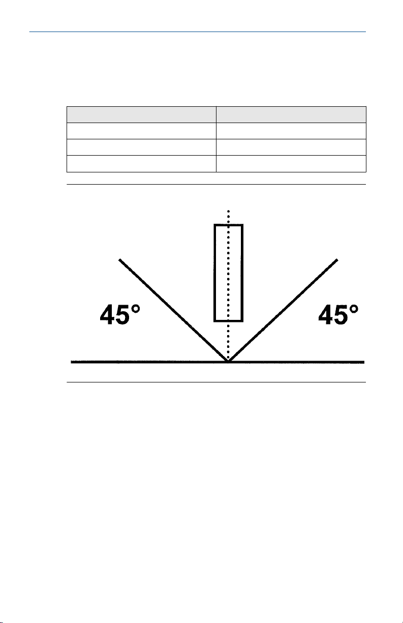
Install the sensor in a flowing sample. Keep the sample flow as constant as
possible at a value within the following limits:
Sample flow unit Flow limits
Flow through 1 to 5 gpm (3.8 to 19 L/min)
Open channel 1 ft/sec (0.3 m/sec)
Low flow cell 2 to 5 gph (7.6 to 19 L/hr)
Figure 2-1: Sensor Orientation
Install sensor within 45 degrees of vertical.
6 Emerson.com/Rosemount
Page 7
November 2019 Quick Start Guide
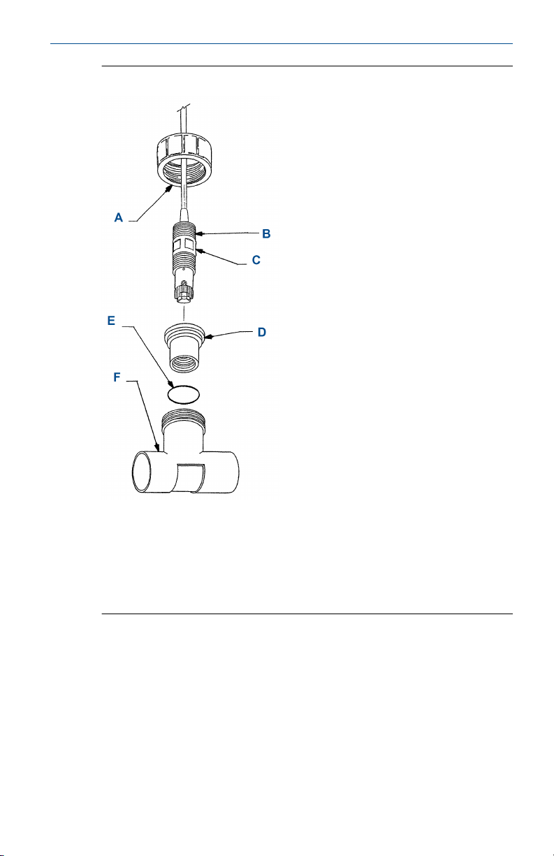
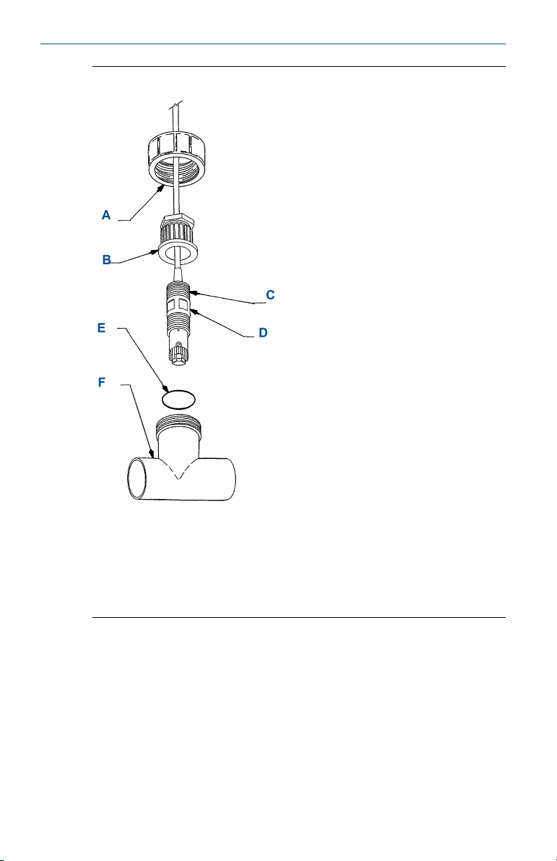
Figure 2-2: Flow Through 1½-in. Tee
A. Union coupler
B. 1-in. national pipe thread (NPT), two places
C. Sensor body: Rosemount 499A
D. 1-in. NPT flow cell adapter
E. O-ring 2-222
F. 1½-in. sched 80 CPVC tee body
Quick Start Guide 7
Page 8
Quick Start Guide November 2019
Figure 2-3: Flow Through 2-in. Tee
A. Union coupler
B. Adapter
C. 1-in. NPT (two places)
D. Sensor body: Rosemount 499A
E. O-ring 2-222
F. 2-in. sched 80 PVC tee body
8 Emerson.com/Rosemount
Page 9

November 2019 Quick Start Guide
Figure 2-4: Low Flow Cell (PN 24091-00)
A. Inches
B. Millimeters
C. Outlet
D. Inlet
Quick Start Guide 9
Page 10

Quick Start Guide November 2019
3 Wire
NOTICE
For additional wiring information on this product, including sensor
combinations not shown here, please refer to the Liquid Transmitter Wiring
Diagrams.
Figure 3-1: Rosemount 499AOZ Sensor Wiring to Rosemount 1056 and
56 Transmitters
Table 3-1: Rosemount 499AOZ Sensor Wiring to Rosemount 1056 and 56
Transmitters
Terminal
number
1 A White Resistance temperature
2 B White/red RTD sense
3 C Red RTD in
4 D Clear RTD shield
5 N/A N/A +5 V out
6 N/A N/A -4.5 V out
7 D Clear Anode shield
8 E Gray Anode
9 D Clear Cathode shield
10 Emerson.com/Rosemount
Letter Wire color Description
device (RTD) return
Page 11

November 2019 Quick Start Guide
Table 3-1: Rosemount 499AOZ Sensor Wiring to Rosemount 1056 and 56
Transmitters (continued)
Terminal
number
10 F Orange Cathode
Letter Wire color Description
Figure 3-2: Rosemount 499AOZ Sensor Wiring to Rosemount 5081
Transmitter
Table 3-2: Rosemount 499AOZ Sensor Wiring to Rosemount 5081 Transmitter
Terminal
number
1 N/A N/A N/A
2 N/A N/A +0.8 V
3 A White RTD return
Quick Start Guide 11
Letter Wire color Description
Page 12

Quick Start Guide November 2019
Table 3-2: Rosemount 499AOZ Sensor Wiring to Rosemount 5081 Transmitter
(continued)
Terminal
number
4 B White/red RTD sense
5 C Red RTD in
6 N/A N/A Reference guard
7 N/A N/A Reference in
8 D Clear Solution ground
9 N/A N/A pH guard
10 N/A N/A pH in
11 N/A N/A -5 V
12 N/A N/A +5 V
13 E Gray Anode
14 F Orange Cathode
15 N/A N/A HART®/FOUNDATION™ Fieldbus
16 N/A N/A HART/FOUNDATION Fieldbus (+)
Letter Wire color Description
(-)
12 Emerson.com/Rosemount
Page 13

November 2019 Quick Start Guide
Figure 3-3: Rosemount 499AOZ Sensor Wiring to Rosemount 1066
Transmitter
Note
Connect clear shield wires to solution ground terminal on TB 2. Use wire nut
and pigtail if necessary.
Table 3-3: Rosemount 499AOZ Wiring to Rosemount 1066 Transmitter
Letter Color Terminal description
A Orange Cathode
B Gray Anode
C White Return
D White/red Sense
E Red RTD in
Quick Start Guide 13
Page 14

Quick Start Guide November 2019
Figure 3-4: Rosemount 499AOZ Sensor Pin-out Diagram
Table 3-4: Pin-out Diagram
Terminal number Description
1 Cathode
2 N/A
3 RTD sense
4 Anode
5 RTD return
6 RTD in
When making a connection through a junction box (PN 23550-00), wire
point-to-point.
NOTICE
Use a wire nut and pigtail (included) when connecting several wires to the
same terminal.
14 Emerson.com/Rosemount
Page 15

November 2019 Quick Start Guide
4 Calibrate
4.1 Zero point calibration
Even in the absence of ozone, the sensor generates a small signal called the
zero current. Failing to correct for the zero current can introduce a bias,
particularly if the ozone concentration is small (<0.4 ppm). Zero the sensor
when it is first placed in service and every time the fill solution is changed.
To zero the sensor:
Procedure
1. Pour a cup of deionized or bottled water.
2. Place the sensor in the water.
3. Wait until the sensor current has reached a stable low value (at least
two hours).
4. Follow the transmitter prompts for zeroing the sensor.
Note
Refer to the manual for the transmitter you are using (Rosemount
56, 1056, 5081, or 1066).
The zero current should be between -10 and +10 nA.
4.2 Full scale calibration
Because stable dilute ozone standards are not available, the sensor must be
calibrated against the results of a laboratory test run on a grab sample of the
process liquid.
Procedure
1. Place the sensor in the flow cell.
2. Start the sample and reagent flow.
3. Adjust the sample flow to the correct range.
4. Adjust the concentration so that it is near the upper end of the
operating range.
5. Wait for the readings to stabilize.
6. Follow the transmitter prompts to complete the calibration.
Note
Refer to the manual for the transmitter you are using (Rosemount
56, 1056, 5081, or 1066).
7. After calibration, go to the Diagnostics menu and check the
sensitivity.
Quick Start Guide 15
Page 16

Quick Start Guide November 2019
The sensitivity should be between 250 and 450 nA/ppm. For more
information, refer to the transmitter manual.
16 Emerson.com/Rosemount
Page 17

November 2019 Quick Start Guide
5 Maintenance
Periodic maintenance and cleaning are required for best performance of the
sensor. Generally, the membrane and fill solution should be replaced every
four to six months. Sensors installed in harsh or dirty environments require
more frequent maintenance. The optimum maintenance frequency is best
determined by experience.
WARNING
Pressurized spray injury
Before removing the sensor, be absolutely certain that the process pressure
is reduced to 0 psig and the process temperature is lowered to a safe level!
5.1 Cleaning the membrane
Keep the membrane and sensor tip clean and free from dirt. Clean the
membrane with water sprayed from a wash bottle. Use a soft tissue to
gently wipe the membrane.
5.2 Replacing the electrolyte solution and membrane
WARNING
Harmful substance
Fill solution may cause irritation. May be harmful if swallowed.
Read and follow the instructions.
Procedure
1. Unscrew the membrane retainer.
2. Remove the membrane assembly and O-ring.
See Figure 1-1.
3. Hold the sensor over a container with the cathode pointing down.
4. Remove the fill plug.
5. Allow the electrolyte solution to drain out.
6. Inspect the cathode.
a) If it is tarnished, clean it by gently rubbing in the direction of
the existing scratches (do not use a circular motion) with
400-600 grit silicon carbide finishing paper.
b) Rinse thoroughly with water.
Quick Start Guide 17
Page 18

Quick Start Guide November 2019
7. Remove the old pipe tape from the plug.
8. Wrap the plug with one or two turns of pipe tape..
9. Prepare a new membrane.
a) Hold the membrane assembly with the cup formed by the
membrane and membrane holder pointing up.
b) Fill the cup with electrolyte solution.
c) Leave the membrane assembly filled with electrolyte solution
and set it aside.
10. Hold the sensor at about a 45 degree angle with the cathode end
pointing up.
11. Add electrolyte solution through the fill hole until the liquid
overflows.
12. Tap the sensor near the threads to release trapped air bubbles.
13. Add more electrolyte solution if necessary.
14. Place the fill plug in the electrolyte port and begin screwing it in.
15. After several threads have engaged, rotate the sensor so that the
cathode is pointing up and continue tightening the fill plug.
Do not overtighten.
16. Place a new O-ring in the groove around the cathode post.
17. Cover the holes at the base of the cathode stem with several drops of
electrolyte solution.
18. Insert a small blunt probe, like a toothpick with the end cut off,
through the pressure equalizing port.
See Figure 1-1.
CAUTION
Equipment damage
A sharp probe may puncture the bladder and destroy the sensor.
Do not use a sharp probe.
19. Gently press the probe against the bladder several times to force
liquid through the holes at the base of the cathode stem. Keep
pressing the bladder until no air bubbles can be seen leaving the
holes.
Be sure the holes remain covered with electrolyte solution.
20. Place a drop of electrolyte solution on the cathode; then place the
membrane assembly over the cathode.
21. Screw the membrane retainer in place.
18 Emerson.com/Rosemount
Page 19

November 2019 Quick Start Guide
The sensor may require several hours operating at the polarizing
voltage to equilibrate after the electrolyte solution has been
replenished.
Quick Start Guide 19
Page 20

Quick Start Guide November 2019
6 Accessories
Part number Description
23747-06 Interconnecting cable, Variopol (VP) 6, 2.5 ft. (0.8 m)
23747-04 Interconnecting cable, VP 6, 4 ft. (1.2 m)
23747-02 Interconnecting cable, VP 6, 10 ft. (3.0 m)
23747-07 Interconnecting cable, VP 6, 15 ft. (4.6 m)
23747-08 Interconnecting cable, VP 6, 20 ft. (6.1 m)
23747-09 Interconnecting cable, VP 6, 25 ft. (7.6 m)
23747-10 Interconnecting cable, VP 6, 30 ft. (9.1 m)
23747-03 Interconnecting cable, VP 6, 50 ft. (15.2 m)
23747-11 Interconnecting cable, VP 6, 100 ft. (30.5 m)
23567-00 1½-in. flow through tee with 1½-in. socket connections
915240-03 2-in. flow through tee with ¾-in. female national pipe
915240-04 2-in. flow through tee with 1-in. FNPT connections
915240-05 2-in. flow through tee with 1½-in. FNPT connections
24091-00 Low flow cell with ¼-in. OD tubing compression fittings
9390004 Rotameter: 0.5 - 5.0 gph
22550-00 Junction box, 12 terminals
9200266 Extension cable for option -54, unterminated (specify
9200275 Extension cable for optimum EMI/RFI cable,
23747-00 Extension cable for optimum EMI/RFI cable, terminated
2001492 Stainless steel tag
23501-11 Dissolved ozone membrane assembly; includes 1
23502-11 Dissolved ozone membrane assembly; includes 3
9210299 #3 Dissolved ozone sensor fill solution, 4 oz (125 ml)
33521-02 Membrane retainer
33523-03 Fill plug
thread (FNPT) connections
length)
unterminated (specify length)
(specify length)
membrane assembly and 1 O-ring
membrane assemblies and 3 O-rings
20 Emerson.com/Rosemount
Page 21

November 2019 Quick Start Guide
Quick Start Guide 21
Page 22

Quick Start Guide November 2019
22 Emerson.com/Rosemount
Page 23

November 2019 Quick Start Guide
Quick Start Guide 23
Page 24

*00825-0100-3492*
EMERSON AUTOMATION SOLUTIONS
6021 Innovation Blvd.
Shakopee, MN 55379
+1 866 347 3427
+1 952 949 7001
RMTNA.RCCPO@Emerson.com
00825-0100-3492, Rev. AB
Quick Start Guide
November 2019
NORTH AMERICA
Emerson Automation Solutions
8200 Market Blvd
Chanhassen, MN 55317
Toll Free +1 800 999 9307
F +1 952 949 7001
RMTNA.RCCPO@Emerson.com
MIDDLE EAST AND AFRICA
Emerson Automation Solutions
Emerson FZE
Jebel Ali Free Zone
Dubai, United Arab Emirates, P.O. Box
17033
+971 4 811 8100
+971 4 886 5465
RMTNA.RCCPO@Emerson.com
Linkedin.com/company/Emerson-
Automation-Solutions
twitter.com/rosemount_news
Facebook.com/Rosemount
youtube.com/RosemountMeasurement
EUROPE
Emerson Automation Solutions
Neuhofstrasse 19a PO Box 1046
CH-6340 Baar
Switzerland
+41 (0) 41 768 6111
+41 (0) 41 768 6300
RMTNA.RCCPO@Emerson.com
ASIA-PACIFIC
Emerson Automation Solutions
1 Pandan Crescent
Singapore 128461
Republic of Singapore
+65 6 777 8211
+65 6 777 0947
RMTNA.RCCPO@Emerson.com
©
2020 Emerson. All rights reserved.
The Emerson logo is a trademark and service
mark of Emerson Electric Co. Rosemount is a
mark of one of the Emerson family of companies.
All other marks are the property of their
respective owners.
 Loading...