

Emerson Rosemount 485 Quick Start Manual
Quick Start Guide
00825-0700-4809, Rev BA
June 2016
Rosemount™ 485 Annubar™ Threaded
Assembly

Quick Start Guide
June 2016
NOTICE
This guide provides basic guidelines for Rosemount 485. It does not provide instructions for configuration,
diagnostics, maintenance, service, troubleshooting, Explosion-proof, Flameproof, or Intrinsically Safe (I.S.)
installations. Refer to Rosemount 485 Annubar Reference Manual
available electronically on EmersonProcess.com/Rosemount
If the Rosemount 485 was ordered assembled to a Rosemount Pressure Transmitter, see the following Quick
Start Guides for information on configuration and hazardous locations certifications:
Rosemount 3051S Series Pressure Transmitter and Rosemount 3051SF Series Flowmeter Quick Start
Guide.
Rosemount 3051S MultiVariable Transmitter and Rosemount 3051SF Series Flowmeter MultiVariable
Tra ns mi tt er Quick Start Guide
Rosemount 3051 Pressure Transmitter and Rosemount 3051CF Series Flowmeter Transmitter Quick
Start Guide.
Rosemount 2051 Pressure Transmitter and Rosemount 2051CF Series Flowmeter Transmitter Quick
Start Guide.
Process leaks may cause harm or result in death. To avoid process leaks, only use packings designed to seal
with the recommended torque value to seal process connections. Flowing medium may cause the
Rosemount 485 Annubar Assembly to become hot and could result in burns.
.
for more instruction. This manual is also
.
Contents
Location and orientation . . . . . . . . . . . . . . . . . . 5
Drill sensor holes . . . . . . . . . . . . . . . . . . . . . . . . 11
Prepare for welding . . . . . . . . . . . . . . . . . . . . . . 11
2
Weld the mounting hardware . . . . . . . . . . . . . 12
Insert the Rosemount Annubar Sensor . . . . . 12
Product certifications . . . . . . . . . . . . . . . . . . . . 15
June 2016
Quick Start Guide
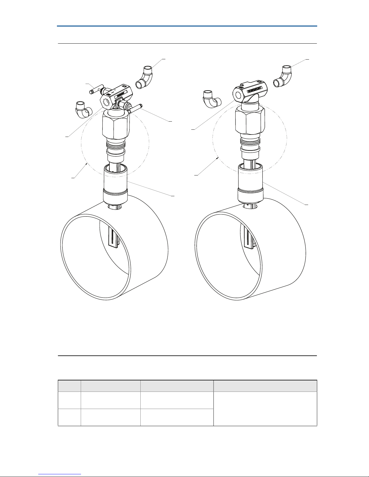
Figure 1. Rosemount 485 Annubar Threaded Assembly Exploded View
E
C
D
G
B
E
A
F
A. See Figure 2 for detail.
B. Remote mount connection with isolation valves
C. Integrated valve low (VL)
D. Integrated valve high (VH)
A
F
E. 2⫻ Elbows
F. Threaded weld coupling
G. Remote mount connection
Table 1. Isolation Valves
Name Description Position Purpose
VH
1. High pressure
2. Low pressure
Integrated Isolation
Val ve High
Integrated Isolation
VL
Val ve Low
(1)
(2)
Letter “H” side of the
Remote Mount Connection
Letter “L” side of the Remote
Mount Connection
Isolates high side or low side pressure
from the process
3

Quick Start Guide
Figure 2. Rosemount 485 Annubar Threaded Packing Assembly Detail
Exploded View
(1)
June 2016
B
A
A. 3⫻ Packaging rings
B. Follower
C. Nut
C
D
E
D. Retaining ring
E. Rosemount 485 Annubar Sensor
1. Image scale = 3/2.
4
June 2016
Quick Start Guide
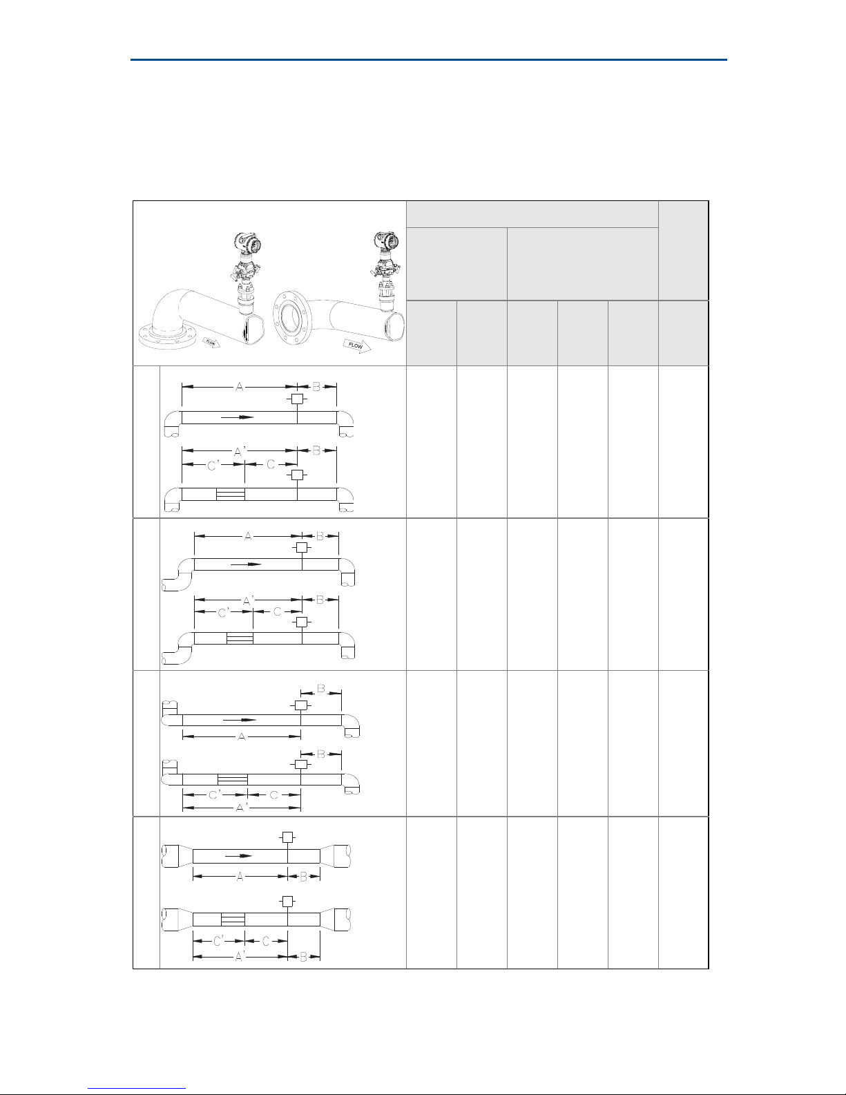
1.0 Location and orientation
Correct orientation and straight run requirements must be met for accurate and
repeatable flow measurements. Refer to Table 2 for minimum pipe diameter
distances from upstream and downstream disturbances.
Table 2. Straight Run Requirements
In plane____________Out of plane Upstream pipe diameters
Without
straightening
vanes
In
Out of
plane
1
N/A
11
2
N/A
plane
A
8
A
10
N/A
16
N/A
With straightening
vanes
A’ C C’ B
N/A
8
N/A
8
N/A
4
N/A
4
N/A
4
N/A
4
Downstream
4
4
4
4
pipe diameters
3
4
23
N/A
12
N/A
28
N/A
12
N/A
N/A
8
N/A
8
N/A
4
N/A
4
N/A
4
N/A
4
4
4
4
4
5
Quick Start Guide
3
3
3
June 2016
18
5
N/A
30
6
N/A
18
N/A
30
N/A
N/A
8
N/A
8
N/A
4
N/A
4
N/A
4
N/A
4
Note
Consult the factory for instructions regarding use in square or rectangular
ducts.
If proper lengths of straight run are not available, position the mounting such
that 80% of the run is upstream and 20% is downstream. This will result in
degraded accuracy.
Use straightening vanes to reduce the required straight run length.
Row 6 in Ta b le 2 applies to gate, globe, plug, and other throttling valves that
are partially opened, as well as control valves.
4
4
4
4
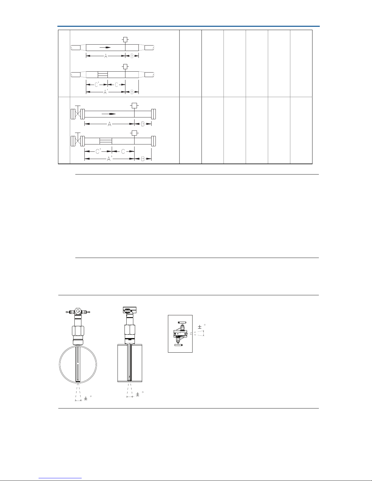
1.1 Misalignment
Rosemount 485 installation allows for a maximum misalignment of 3°.
Figure 3. Misalignment
6
 Loading...