

Page 1
00809-0100-4022, Rev GA
Aotewell Ltd
www.aotewell.com
Industry Automation
HongKong|UK|China
sales@aotewell.com
+86-755-8660-6182
Rosemount™ 4600 Oil & Gas Panel
Transmitter
Reference Manual
September 2016
Page 2

Aotewell Ltd
www.aotewell.com
Industry Automation
HongKong|UK|China
sales@aotewell.com
+86-755-8660-6182
Page 3

Reference Manual
Aotewell Ltd
www.aotewell.com
Industry Automation
HongKong|UK|China
sales@aotewell.com
+86-755-8660-6182
00809-0100-4022, Rev GA
Contents
1Section 1: Introduction
2Section 2: Configuration
Table of Contents
September 2016
1.1 Using this manual. . . . . . . . . . . . . . . . . . . . . . . . . . . . . . . . . . . . . . . . . . . . . . . . . . . . . . 1
1.2 Product recycling/disposal . . . . . . . . . . . . . . . . . . . . . . . . . . . . . . . . . . . . . . . . . . . . . . 1
2.1 Overview . . . . . . . . . . . . . . . . . . . . . . . . . . . . . . . . . . . . . . . . . . . . . . . . . . . . . . . . . . . . .3
2.2 Safety messages. . . . . . . . . . . . . . . . . . . . . . . . . . . . . . . . . . . . . . . . . . . . . . . . . . . . . . .3
2.3 Commissioning on the bench with HART . . . . . . . . . . . . . . . . . . . . . . . . . . . . . . . . .4
2.4 Field Communicator . . . . . . . . . . . . . . . . . . . . . . . . . . . . . . . . . . . . . . . . . . . . . . . . . . .5
2.5 Review configuration data . . . . . . . . . . . . . . . . . . . . . . . . . . . . . . . . . . . . . . . . . . . . . .6
2.6 Check output . . . . . . . . . . . . . . . . . . . . . . . . . . . . . . . . . . . . . . . . . . . . . . . . . . . . . . . . . 7
2.7 Basic setup. . . . . . . . . . . . . . . . . . . . . . . . . . . . . . . . . . . . . . . . . . . . . . . . . . . . . . . . . . . . 9
2.8 Detailed setup. . . . . . . . . . . . . . . . . . . . . . . . . . . . . . . . . . . . . . . . . . . . . . . . . . . . . . . .12
2.9 Diagnostics and service. . . . . . . . . . . . . . . . . . . . . . . . . . . . . . . . . . . . . . . . . . . . . . . .16
2.10 Advanced functions for HART protocol . . . . . . . . . . . . . . . . . . . . . . . . . . . . . . . . .18
2.11 Multidrop communication . . . . . . . . . . . . . . . . . . . . . . . . . . . . . . . . . . . . . . . . . . . .22
3Section 3: Installation
3.1 Overview . . . . . . . . . . . . . . . . . . . . . . . . . . . . . . . . . . . . . . . . . . . . . . . . . . . . . . . . . . . .25
3.2 Safety messages. . . . . . . . . . . . . . . . . . . . . . . . . . . . . . . . . . . . . . . . . . . . . . . . . . . . . .25
3.3 General considerations . . . . . . . . . . . . . . . . . . . . . . . . . . . . . . . . . . . . . . . . . . . . . . . .26
3.4 Mechanical considerations. . . . . . . . . . . . . . . . . . . . . . . . . . . . . . . . . . . . . . . . . . . . .26
3.5 Installation procedures . . . . . . . . . . . . . . . . . . . . . . . . . . . . . . . . . . . . . . . . . . . . . . . .28
3.6 Hazardous locations . . . . . . . . . . . . . . . . . . . . . . . . . . . . . . . . . . . . . . . . . . . . . . . . . .32
3.7 Grounding the transmitter case . . . . . . . . . . . . . . . . . . . . . . . . . . . . . . . . . . . . . . . .33
4Section 4: Operation and Maintenance
4.1 Overview . . . . . . . . . . . . . . . . . . . . . . . . . . . . . . . . . . . . . . . . . . . . . . . . . . . . . . . . . . . .35
®
4.2 Calibration for HART
4.3 Sensor trim . . . . . . . . . . . . . . . . . . . . . . . . . . . . . . . . . . . . . . . . . . . . . . . . . . . . . . . . . .40
4.4 Recall factory trim . . . . . . . . . . . . . . . . . . . . . . . . . . . . . . . . . . . . . . . . . . . . . . . . . . . .43
4.5 Analog output trim . . . . . . . . . . . . . . . . . . . . . . . . . . . . . . . . . . . . . . . . . . . . . . . . . . .44
protocol . . . . . . . . . . . . . . . . . . . . . . . . . . . . . . . . . . . . . . . . .35
Table of Contents
5Section 5: Troubleshooting
5.1 Overview . . . . . . . . . . . . . . . . . . . . . . . . . . . . . . . . . . . . . . . . . . . . . . . . . . . . . . . . . . . .47
5.2 Safety messages. . . . . . . . . . . . . . . . . . . . . . . . . . . . . . . . . . . . . . . . . . . . . . . . . . . . . .47
3
Page 4

Table of Contents
Aotewell Ltd
www.aotewell.com
Industry Automation
HongKong|UK|China
sales@aotewell.com
+86-755-8660-6182
September 2016
AAppendix A: Specification and Reference Data
BAppendix B: Product Certifications
Reference Manual
00809-0100-4022, Rev GA
A.1 Ordering Information . . . . . . . . . . . . . . . . . . . . . . . . . . . . . . . . . . . . . . . . . . . . . . . . .51
A.2 Specifications . . . . . . . . . . . . . . . . . . . . . . . . . . . . . . . . . . . . . . . . . . . . . . . . . . . . . . . .54
A.3 Dimensional drawings. . . . . . . . . . . . . . . . . . . . . . . . . . . . . . . . . . . . . . . . . . . . . . . . .57
B.1 European Directive Information . . . . . . . . . . . . . . . . . . . . . . . . . . . . . . . . . . . . . . . .59
B.2 Ordinary Location Certification . . . . . . . . . . . . . . . . . . . . . . . . . . . . . . . . . . . . . . . . .59
B.3 Approval drawings . . . . . . . . . . . . . . . . . . . . . . . . . . . . . . . . . . . . . . . . . . . . . . . . . . . .62
4
Table of Contents
Page 5

Reference Manual
NOTICE
Aotewell Ltd
www.aotewell.com
Industry Automation
HongKong|UK|China
sales@aotewell.com
+86-755-8660-6182
00809-0100-4022, Rev GA
Rosemount™ 4600
Oil & Gas Panel Transmitter
Read this manual before working with the product. For personal and system safety, and
for optimum product performance, make sure you thoroughly understand the
contents before installing, using, or maintaining this product.
Emerson
Customer Central
Technical support, quoting, and order-related questions.
United States - 1-800-999-9307 (7:00 am to 7:00 pm CST)
Asia Pacific- 65 777 8211
Europe/Middle East/Africa - 49 (8153) 9390
North American Response Center
Equipment service needs.
1-800-654-7768 (24 hours—includes Canada)
Outside of these areas, contact your local Emerson
representative.
™
Process Management has two toll-free assistance numbers:
Process Management
Title Page
September 2016
Title Page
The products described in this document are NOT designed for nuclear-qualified
applications. Using non-nuclear qualified products in applications that require
nuclear-qualified hardware or products may cause inaccurate readings.
For information on Rosemount nuclear-qualified products, contact your local Emerson
Process Management.
Apply torque only to the hex flat located at the process end of the transmitter. Do not
apply torque to the transmitter body or electrical connection - severe damage could
result. Do not exceed 100 ft-lbs.
Static electricity can damage sensitive components.
Observe safe handling precautions for static-sensitive components.
i
Page 6

Title Page
Aotewell Ltd
www.aotewell.com
Industry Automation
HongKong|UK|China
sales@aotewell.com
+86-755-8660-6182
September 2016
Reference Manual
00809-0100-4022, Rev GA
Explosions can result in death or serious injury.
Transmitters located in hazardous areas should be installed in accordance with
local codes and requirements for that area.
Use appropriately rated Ex adapters, blanking elements, and glands during
installation.
Keep process insulation at least 1-in. [25 mm] from transmitter connection.
Electrical shock can result in death or serious injury.
Avoid contact with the exposed leads and terminals. High voltage that may be
present on leads can cause electrical shock.
Process leaks could result in death or serious injury.
Properly tighten process connections before applying pressure.
ii
Title Page
Page 7

Reference Manual
Aotewell Ltd
www.aotewell.com
Industry Automation
HongKong|UK|China
sales@aotewell.com
+86-755-8660-6182
00809-01000-4022, Rev GA
Section 1 Introduction
1.1 Using this manual
The sections in this manual provides information on installing, operating, and maintaining
the Rosemount
Section 2: Configuration contains mechanical and electrical installation
Section 3: Installation provides instruction on commissioning and configuring the
Section 4: Operation and Maintenance contains operation and maintenance
Section 5: Troubleshooting provides troubleshooting techniques for the most
™
4600 Oil & Gas Pressure Transmitter. The sections are organized as follows:
instructions.
Rosemount 4600 Transmitter. Information on software functions, configuration
parameters, and online variables is also included.
instructions.
common operating problems.
Introduction
September 2016
Appendix A: Specification and Reference Data supplies reference and specification
data, as well as ordering information.
Appendix B: Product Certifications contains approval information
1.2 Product recycling/disposal
Recycling of equipment and packaging should be taken into consideration and disposed of
in accordance with local and national legislation/regulations.
Introduction
1
Page 8

Introduction
Aotewell Ltd
www.aotewell.com
Industry Automation
HongKong|UK|China
sales@aotewell.com
+86-755-8660-6182
September 2016
Reference Manual
00809-0100-4022, Rev GA
2
Introduction
Page 9

Reference Manual
Aotewell Ltd
www.aotewell.com
Industry Automation
HongKong|UK|China
sales@aotewell.com
+86-755-8660-6182
00809-0100-4022, Rev GA
Section 2 Configuration
Safety messages . . . . . . . . . . . . . . . . . . . . . . . . . . . . . . . . . . . . . . . . . . . . . . . . . . . . . . . . . . . . page 3
Commissioning on the bench with HART . . . . . . . . . . . . . . . . . . . . . . . . . . . . . . . . . . . . . . . page 4
Field Communicator . . . . . . . . . . . . . . . . . . . . . . . . . . . . . . . . . . . . . . . . . . . . . . . . . . . . . . . . page 5
Review configuration data . . . . . . . . . . . . . . . . . . . . . . . . . . . . . . . . . . . . . . . . . . . . . . . . . . . page 6
Check output . . . . . . . . . . . . . . . . . . . . . . . . . . . . . . . . . . . . . . . . . . . . . . . . . . . . . . . . . . . . . . . page 7
Basic setup . . . . . . . . . . . . . . . . . . . . . . . . . . . . . . . . . . . . . . . . . . . . . . . . . . . . . . . . . . . . . . . . . page 9
Detailed setup . . . . . . . . . . . . . . . . . . . . . . . . . . . . . . . . . . . . . . . . . . . . . . . . . . . . . . . . . . . . . . page 12
Diagnostics and service . . . . . . . . . . . . . . . . . . . . . . . . . . . . . . . . . . . . . . . . . . . . . . . . . . . . . . page 16
Advanced functions for HART protocol . . . . . . . . . . . . . . . . . . . . . . . . . . . . . . . . . . . . . . . . page 18
Multidrop communication . . . . . . . . . . . . . . . . . . . . . . . . . . . . . . . . . . . . . . . . . . . . . . . . . . . page 22
2.1 Overview
Configuration
September 2016
This section contains information on commissioning and tasks that should be performed on the
bench prior to installation. This section contains the Rosemount
Transm itter HART
Field Communicator and AMS
functions. For convenience, Field Communicator Fast Key sequences are labeled “Fast Keys” for
each software function below the appropriate headings.
®
configuration information.
™
2.2 Safety messages
Procedures and instructions in this section may require special precautions to ensure the safety
of the personnel performing the operations. Information that raises potential safety issues is
indicated by a warning symbol ( ). Refer to the following safety messages before performing
an operation preceded by this symbol.
Explosions can result in death or serious injury.
Transmitters located in hazardous areas should be installed in accordance with local
codes and requirements for that area.
Verify that the operating atmosphere of the transmitter is consistent with the
appropriate hazardous locations certifications.
Electrical shock can result in death or serious injury.
Avoid contact with the exposed leads and terminals. High voltage that may be present
on leads can cause electrical shock.
™
4600 Oil & Gas Pressure
Device Manager instructions are given to perform configuration
Configuration
3
Page 10

Configuration
Aotewell Ltd
www.aotewell.com
Industry Automation
HongKong|UK|China
sales@aotewell.com
+86-755-8660-6182
September 2016
Reference Manual
00809-0100-4022, Rev GA
2.3 Commissioning on the bench with HART
Commissioning consists of testing the Rosemount 4600 and verifying transmitter
configuration data. The transmitter can be commissioned either before or after installation.
Commissioning the transmitter on the bench before installation using a Field
Communicator or AMS Device Manager ensures that all transmitter components are in
working order.
To commission on the bench, connect the transmitter and the Field Communicator or AMS
Device Manager. Connect Field Communicator leads at any termination point in the signal
loop.
In order to commission the transmitter, the power supply must provide 11.25 to
42.4 V dc at the transmitter terminals. A current meter is also required to measure current
output. To enable communication, a resistance of at least 250 ohms must be present
between the Field Communicator loop connection and the power supply. Do not use
inductive-based transient protectors with more than 3 mH of inductance with the
Rosemount 4600.
When using a Field Communicator, any configuration changes made must be sent to the
transmitter by using the “Send” key (F2). AMS Device Manger configuration changes are
implemented when the “Apply” button is selected.
For more information on the Field Communicator, see 475 Field Communicator website for
the most up to date literature. AMS Device Manger help can be found in the AMS Device
Manager online guides within the AMS system.
2.3.1 Setting the loop to manual
Whenever sending or requesting data that would disrupt the loop or change the output of
the transmitter, set the process application loop to manual. The Field Communicator or
AMS Device Manager will prompt you to set the loop to manual when necessary.
Acknowledging this prompt does not set the loop to manual. The prompt is only a
reminder; set the loop to manual as a separate operation.
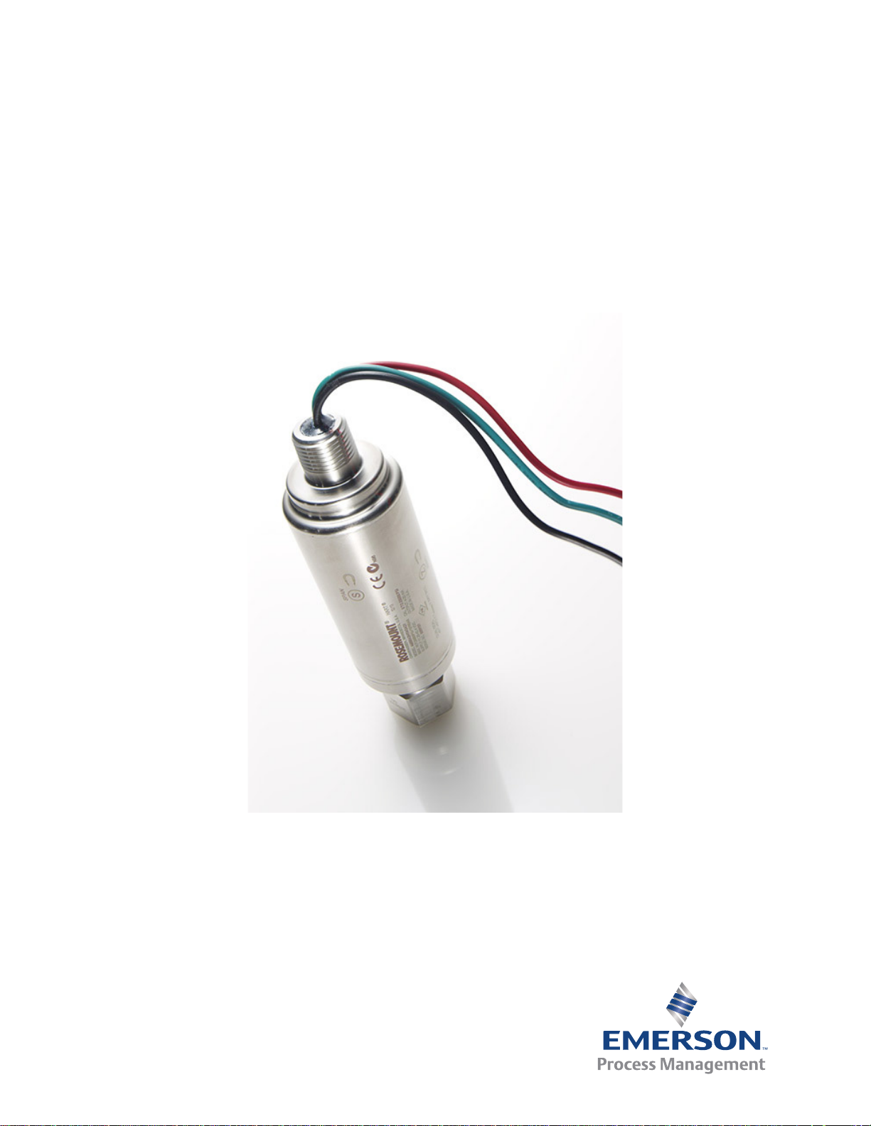
2.3.2 Wiring diagrams
Bench hook-up
Connect the bench equipment as shown in Figure 2-1 and turn on the Field Communicator
by pressing the ON/OFF key or log into AMS Device Manager. The Field Communicator or
AMS Device Manager will search for a HART-compatible device and indicate when the
connection is made. If the Field Communicator or AMS Device Manager fail to connect, it
indicates that no device was found. If this occurs, refer to Section 5: Troubleshooting.
4
Configuration
Page 11
Reference Manual
B
D
C
A
E
Aotewell Ltd
www.aotewell.com
Industry Automation
HongKong|UK|China
sales@aotewell.com
+86-755-8660-6182
00809-0100-4022, Rev GA
Figure 2-1. Bench Wiring (4–20 mA)
Configuration
September 2016
A. Rosemount 4600
B. R
> 250 ohm
L
C. Power supply
2.4 Field Communicator
The following menu indicates Fast Key sequences for common functions. For full Field
Communicator menu tree see EmersonProcess.com/Rosemount
Func tion HART Fast Key Sequence
Alarm Level Config. 1, 4, 2, 7, 7
Alarm and Saturation Levels 1, 4, 2, 7
Analog Output Alarm Direction 1, 4, 2, 7, 6
Analog Output Trim 1, 2, 3, 2
Burst Mode On/Off 1, 4, 3, 3, 3
Burst Options 1, 4, 3, 3, 4
Damping 1, 3, 6
Date 1, 3, 4, 1
D. Current meter
E. Field Communicator
.
Configuration
Descriptor 1, 3, 4, 2
Digital To Analog Trim (4-20 mA Output) 1, 2, 3, 2, 1
Field Device Information 1, 4, 4, 1
Loop Test 1, 2, 2
Lower Sensor Trim 1, 2, 3, 3, 1
Message 1, 3, 4, 3
Number of Requested Preambles 1, 4, 3, 3, 2
Pressure Alert Config. 1, 4, 3, 4, 3
5
Page 12

Configuration
Aotewell Ltd
www.aotewell.com
Industry Automation
HongKong|UK|China
sales@aotewell.com
+86-755-8660-6182
September 2016
Reference Manual
00809-0100-4022, Rev GA
Func tion HART Fast Key Sequence
Poll Address 1, 4, 3, 3, 1
Poll a Multidropped Transmitter Left Arrow, 3, 1, 1
Rerange- Keypad Input 1, 2, 3, 1, 1
Saturation Level Config. 1, 4, 2, 7, 8
Scaled D/A Trim (4–20 mA Output) 1, 2, 3, 2, 2
Sensor Information 1, 4, 4, 2
Sensor Temperature 1, 1, 4
Sensor Trim 1, 2, 3, 3
Sensor Trim Points 1, 2, 3, 3, 4
Status 1, 2, 1
Ta g 1, 3, 1
Temperature Alert Config. 1, 4, 3, 4, 4
Transmitter Security (Write Protect) 1, 3, 4, 4
Units (Process Variable) 1, 3, 2
Upper Sensor Trim 1, 2, 3, 3, 2
Zero Trim 1, 2, 3, 3, 1
2.5 Review configuration data
Fast Keys
Note
Information and procedures in this section that make use of Field Communicator Fast Key
sequences and AMS Device Manager assume the transmitter and communication
equipment are connected, powered, and operating correctly.
1, 5
6
Configuration
Page 13

Reference Manual
Aotewell Ltd
www.aotewell.com
Industry Automation
HongKong|UK|China
sales@aotewell.com
+86-755-8660-6182
00809-0100-4022, Rev GA
Field Communicator
Before placing the transmitter into operation, review the transmitter configuration data
below which was set by the factory.
PV Lower Sensor Limit (LSL) Ta g
PV Upper Sensor Limit (USL) Date
PV Lower Range Value (LRV) Descriptor
PV Upper Range Value (URV) Message
PV minimum span Write protect
Lower sensor trim point Local keys
Upper sensor trim point Universal revision
Sensor trim calibration type Field device revision
Damping Software revision
Alarm direction Hardware revision
High Alarm (Value) Physical signal code
Low Alarm (Value) Final assembly number
High saturation Device ID
Low saturation Burst mode
Alarm/Saturation type Burst option
Sensor S/N Poll address
Isolator material Number req preams
Fill fluid Distributor
Process connector
Process connector material
Configuration
September 2016
AMS Device Manger
Right click on the device and select Configuration Properties from the menu. Select the
tabs to review the transmitter configuration data.
2.6 Check output
Before performing other transmitter online operations, review the digital output
parameters to ensure the transmitter is operating properly and is configured to the
appropriate process variables.
2.6.1 Process variables
Fast Keys
The process variables for the Rosemount 4600 provide transmitter output, and are
continuously updated. The pressure reading in both engineering units and percent of range
will continue to track with pressures outside of the defined range from the lower to the
upper range limit.
1, 1
Configuration
7
Page 14

Configuration
Aotewell Ltd
www.aotewell.com
Industry Automation
HongKong|UK|China
sales@aotewell.com
+86-755-8660-6182
September 2016
Reference Manual
00809-0100-4022, Rev GA
Field Communicator
The process variable menu displays the following process variables:
Pressure
Percent of range
Analog output
Sensor temperature
Note
Regardless of the range points, the Rosemount 4600 will measure and report all readings
within the digital limits of the sensor. For example, if the 4 and 20 mA points are set to
0 and 1,000 psi, and the transmitter detects a pressure of 2,500 psi, it digitally outputs the
2,500 psi reading and a 250% of span reading. However, there may be up to ±5.0% error
associated with output outside of the range points.
AMS Device Manger
Right click on the device and select Process Variables... from the menu.The process
variable screen displays the following process variables:
Pressure
Percent of range
Analog output
Sensor temperature
2.6.2 Sensor temperature
Fast Keys
The Rosemount 4600 contains a temperature sensor near the pressure sensor in the
transmitter. When reading this temperature, keep in mind this is not an accurate indicator
of process temperature.
Field Communicator
Enter the Fast Key sequence below Sensor Temperature to view the sensor temperature
reading.
AMS Device Manger
Right click on the device and select Process Variables... from the menu. Snsr Temp is the
sensor temperature reading.
1, 1, 4
8
Configuration
Page 15

Reference Manual
Aotewell Ltd
www.aotewell.com
Industry Automation
HongKong|UK|China
sales@aotewell.com
+86-755-8660-6182
00809-0100-4022, Rev GA
2.7 Basic setup
2.7.1 Set process variable units
Configuration
September 2016
Fast Keys
The PV Unit command sets the process variable units to allow you to monitor your process
using the appropriate units of measure.
Field Communicator
Enter the Fast Key sequence shown. Select from the following engineering units:
inH
O bar torr
2
inHg mbar atm
ftH
O g/cm
2
mmH
mmHg Pa mmH
psi kPa
O kg/cm
2
AMS Device Manger
Right click on the device and select Configuration Properties from the menu. In the Basic
Setup tab, use Unit drop down menu to select units.
2.7.2 Rerange
The Range Values command sets the 4 and 20 mA points and digital lower (LRV) and upper
(URV) range values. In practice, you may reset the transmitter range values as often as
necessary to reflect changing process conditions. Changing the lower or upper range point
results in similar changes to the span.
1, 3, 2
2
2
MPa
inH2O at 4 °C
O at 4 °C
2
Configuration
Note
Transmitters are shipped from Emerson Process Management. fully calibrated per request
or by the factory default of full scale (span = upper range limit.)
Use one of the methods below to rerange the transmitter. Each method is unique; examine
all options closely before deciding which method works best for your process.
Rerange with a Field Communicator only.
Rerange with a pressure input source and a Field Communicator.
Rerange with a pressure input source and the local zero and span targets (option
D1).
Rerange with AMS Device Manger only.
Rerange with a pressure input source and AMS Device Manger.
9
Page 16

Configuration
Aotewell Ltd
www.aotewell.com
Industry Automation
HongKong|UK|China
sales@aotewell.com
+86-755-8660-6182
September 2016
Reference Manual
00809-0100-4022, Rev GA
Rerange with a Field Communicator only
Fast Keys
The easiest and most popular way to rerange is to use the Field Communicator only. This
method changes the values of the analog 4 and 20 mA points independently without a
pressure input.
From the HOME screen, enter the Fast Key sequence shown.
1. At Keypad Input select 1 and use the keypad to enter lower range value.
2. From Keypad Input select 2 and use the keypad to enter upper range value.
1, 2, 3, 1, 1
Rerange with a pressure input source and Field
Communicator
Fast Keys
Reranging using the Field Communicator and a pressure source or process pressure is a way
of reranging the transmitter when specific 4 and 20 mA points are unknown.
Note
The span is maintained when the 4 mA point is set. The span changes when the 20 mA point
is set. If the lower range point is set to a value that causes the upper range point to exceed
the sensor limit, the upper range point is automatically set to the sensor limit, and the span
is adjusted accordingly.
1, 2, 3, 1, 2
1. From the HOME screen, enter the Fast Key sequence shown to configure lower and
upper range values and follow the online instructions.
Rerange with a pressure input source and the
local zero and span targets (option D1)
1. For Zero based lower range values (gauge only):
Vent the transmitter.
For Non-Zero based lower range values:
Using a pressure source with an accuracy 3 to 10 times the desired calibrated
accuracy, apply a pressure equivalent to the lower range value to the transmitter.
2. Using the supplied magnetic adjustment tool, touch and hold the magnetic end to
the zero adjustment target for at least two seconds, but no longer than ten
seconds.
3. Using a pressure source with an accuracy 3 to 10 times the desired calibrated
accuracy, apply a pressure equivalent to the upper range value to the transmitter.
4. Using the supplied magnetic adjustment tool, touch and hold the magnetic end to
the span adjustment target for at least two seconds, but no longer than ten
seconds.
10
Configuration
Page 17

Reference Manual
B
A
Aotewell Ltd
www.aotewell.com
Industry Automation
HongKong|UK|China
sales@aotewell.com
+86-755-8660-6182
00809-0100-4022, Rev GA
Figure 2-2. Local Zero and Span Locations
A. Magnetic span target
B. Magnetic zero target
Rerange with AMS Device Manger only
Right click on the device and select Configuration Properties from the menu. In the Basic
Setup tab, locate the Analog Output box and perform the following procedure:
Configuration
September 2016
1. Enter the lower range value (LRV) and the upper range value (URV) in the fields
provided. Select Apply.
2. An Apply Parameter Modification screen appears, enter desired information and
select OK.
3. After carefully reading the warning provided, select OK.
Rerange with a pressure input source and AMS Device
Manger
Right click on the device, choose Calibrate, then Apply values from the menu.
1. Select Next after the control loop is set to manual.
2. From the Apply Values menu, follow the online instructions to configure lower and
upper range values.
3. Select Exit to leave the Apply Values screen.
4. Select Next to acknowledge the loop can be returned to automatic control.
5. Select Finish to acknowledge the method is complete.
2.7.3 Damping
Configuration
Fast Keys
The Damp command introduces a delay in processing which increases the response time of
the transmitter; smoothing variations in output readings caused by rapid input changes.
Determine the appropriate damp setting based on the necessary response time, signal
stability, and other requirements of the of loop dynamics of your system. The default
damping value is 0.4 seconds and is user-selectable from 0.3 to 60 seconds.
1, 3, 6
11
Page 18

Configuration
Aotewell Ltd
www.aotewell.com
Industry Automation
HongKong|UK|China
sales@aotewell.com
+86-755-8660-6182
September 2016
AMS Device Manger
Right click on the device and select Configuration Properties from the menu.
1. In the Basic Setup tab, enter the damping value in the Damp field, select Apply.
2. An Apply Parameter Modification screen appears, enter desired information and
select OK.
3. After carefully reading the warning provided, select OK.
2.8 Detailed setup
2.8.1 Failure mode alarm and saturation
The Rosemount 4600 Transmitter automatically and continuously perform self-diagnostic
routines. If the self-diagnostic routines detect a failure, the transmitter drives the output to
configured alarm values. The transmitter will also drive the output to configured saturation
values if the applied pressure goes outside the 4-20 mA range values.
Reference Manual
00809-0100-4022, Rev GA
Note
The failure mode alarm direction can also be configured using the Field Communicator or
AMS Device Manager.
Note
Under some failure conditions, the transmitter will ignore user configured alarm conditions
and drive the transmitter to low alarm.
The Rosemount 4600 Transmitter have three configurable options for failure mode alarm
and saturation levels:
Rosemount (Standard), see Table 2- 1
Custom, see Tab le 2 -2
Table 2-1. Rosemount (Standard) Alarm and Saturation Values
Level 4–20 mA saturation 4–20 mA alarm
Low 3.9 mA ≤ 3.75 mA
High 20.8 mA ≥ 21.75 mA
Table 2-2. Custom Alarm and Saturation Values
Level 4–20 mA saturation 4–20 mA alarm
12
Low 3.7 mA — 3.9 mA 3.6 mA — 3.8 mA
High 20.1 mA — 21.5 mA 20.2 mA — 23.0 mA
Configuration
Page 19

Reference Manual
Aotewell Ltd
www.aotewell.com
Industry Automation
HongKong|UK|China
sales@aotewell.com
+86-755-8660-6182
00809-0100-4022, Rev GA
Failure mode alarm and saturation levels can be configured using a Field Communicator or
AMS Device Manager, see “Alarm and saturation level configuration” on page 13. Per
Ta bl e 2 - 2, custom alarm and saturation levels can be configured between 3.6 mA and
3.9 mA for low values and between 20.1 mA and 23 mA for high values. The following
limitations exist for custom levels:
Low alarm level must be less than the low saturation level
High alarm level must be higher than the high saturation level
High saturation level must not exceed 21.5 mA
Alarm and saturation levels must be separated by at least 0.1 mA
The Field Communicator or AMS Device Manager will provide an error message if a
configuration rule is violated.
2.8.2 Alarm and saturation level configuration
Configuration
September 2016
Fast Keys
1, 4, 2, 7
To configure alarm and saturation levels with a Field Communicator or AMS Device Manager
perform the following procedure:
Field Communicator
1. From the HOME screen, follow the Fast Key sequence under Alarm and Saturation
Levels.
2. Select 7, Config. Alarm Level to configure alarm levels.
3. Select OK after setting the control loop to manual.
4. Select OK to acknowledge current settings.
5. Select desired setting, if OTHER is selected, enter HI and LO custom values.
6. Select OK to acknowledge the loop can be returned to automatic control.
7. Select 8, Config. Sat. Levels to configure saturation levels.
8. Repeat steps 3-6 to configure saturation levels.
Configuration
13
Page 20

Configuration
Aotewell Ltd
www.aotewell.com
Industry Automation
HongKong|UK|China
sales@aotewell.com
+86-755-8660-6182
September 2016
Reference Manual
00809-0100-4022, Rev GA
AMS Device Manger
1. Right click on the device, select Device Configuration,
2. Select Alarm/Saturation Levels,
3. Select Alarm Levels from the menu
.
4. Select Next after setting the control loop to manual.
5. Select Next after acknowledging the current alarm levels.
6. Select the desired alarm settings: NAMUR, Rosemount, Other
7. If Other is selected, enter desired HI Value and LO Value custom values.
8. Select Next to acknowledge new alarm levels.
9. Select Next to acknowledge the loop can be returned to automatic control.
10. Select Finish to acknowledge the method is complete.
11. Right click on the device, select Device Configuration, then select
Alarm/Saturation Levels, then Alarm Levels from the menu
12. Select Saturation Levels.
13. Repeat Step 5 - 11 to configure saturation levels.
2.8.3 Alarm and saturation levels for burst mode
Transmitters set to burst mode handle saturation and alarm conditions differently.
.
14
Alarm conditions
Analog output switches to alarm value
Primary variable is burst with a status bit set
Percent of range follows primary variable
Temperature is burst with a status bit set
Saturation
Analog output switches to saturation value
Primary variable is burst normally
Tem perature is burst normally
Configuration
Page 21

Reference Manual
Aotewell Ltd
www.aotewell.com
Industry Automation
HongKong|UK|China
sales@aotewell.com
+86-755-8660-6182
00809-0100-4022, Rev GA
Configuration
September 2016
2.8.4 Alarm and saturation values for multidrop mode
Transmitters set to multidrop mode handle saturation and alarm conditions differently.
Alarm conditions
Primary variable is sent with a status bit set
Percent of range follows primary variable
Temperature is sent with a status bit set
Saturation
Primary variable is sent normally
Temperature is sent normally
2.8.5 Alarm level verification
To verify the transmitter alarm values, perform a loop test and set the transmitter output to
the alarm value (see Tables 2-1 and 2-2 on page 12, and “Advanced functions for HART
protocol” on page 18). This feature is also useful in testing the reaction of the control
system to a transmitter in an alarm state.
2.8.6 Process alerts
Fast Keys
Process alerts allow the user to configure the transmitter to output a HART message when
the configured data point is exceeded. Process alerts can be set for pressure, temperature,
or both. A process alert will be transmitted continuously if the pressure or temperature set
points are exceeded and the alert mode is ON. An alert will be displayed on a Field
Communicator, or AMS Device Manger status screen. The alert will reset once the value
returns within range.
Note
HI alert value must be higher than the LO alert value. Both alert values must be within the
pressure or temperature sensor limits.
Field Communicator
To configure the process alerts with a Field Communicator, perform the following
procedure:
1. From the HOME screen, follow the Fast Key sequence listed.
2. Select 3, Config Press Alert to configure the pressure alert.
Select 4, Config Temp Alert to configure the temperature alerts.
1, 4, 3, 4
Configuration
3. Use the right arrow key to configure the HI and LO alert values.
4. Use the left arrow to move back to the process alert menu.
Select 1, Press Alert Mode to turn on the pressure alert mode.
Select 2, Temp Alert Mode to turn on the temperature alert mode.
15
Page 22

Configuration
Aotewell Ltd
www.aotewell.com
Industry Automation
HongKong|UK|China
sales@aotewell.com
+86-755-8660-6182
September 2016
AMS Device Manger
Right click on the device and select Configuration Properties from the menu.
1. In the Analog Output tab, locate the Configuration Pressure Alerts box, enter Press Hi Alert
Val and Press Lo Alert Val to configure the pressure alerts.
2. Configure Press Alert Mode to ON or OFF the drop down menu.
3. In the Configuration Temperature Alerts box, enter Temp Hi Alert Val and Temp Lo A lert Val
to configure the temperature alerts.
4. Configure Temp Alert Mode to ON or OFF using the drop down menu and select Apply.
5. An Apply Parameter Modification screen appears, enter desired information and select
OK.
6. After carefully reading the warning provided, select OK.
2.8.7 Sensor temperature unit
Reference Manual
00809-0100-4022, Rev GA
Fast Keys
The Sensor Temperature Unit command selects between Celsius and Fahrenheit units for the
sensor temperature. The sensor temperature output is accessible via HART only.
1, 4, 1, 2, 2
AMS Device Manger
Right click on the device and select Configuration Properties from the menu.
1. In the Process Input tab, use the drop down menu Snsr temp unit to select F (Farenheit)
or C (Celsius). Select Apply.
2. Select Next to acknowledge send warning.
3. Select Finish to acknowledge the method is complete.
4. An Apply Parameter Modification screen appears, enter desired information and select
OK.
5. After carefully reading the warning, select OK.
2.9 Diagnostics and service
Diagnostics and service functions listed below are primarily for use after field installation. The
Transmitter Test feature is designed to verify that the transmitter is operating properly, and can
be performed either on the bench or in the field. The Loop Test feature is designed to verify
proper loop wiring and transmitter output, and should only be performed after you install the
transmitter.
16
Configuration
Page 23

Reference Manual
Aotewell Ltd
www.aotewell.com
Industry Automation
HongKong|UK|China
sales@aotewell.com
+86-755-8660-6182
00809-0100-4022, Rev GA
2.9.1 Loop Test
Configuration
September 2016
Fast Keys
The Loop Test command verifies the output of the transmitter, the integrity of the loop, and the
operations of any recorders or similar devices installed in the loop.
1, 2, 2
Field Communicator
To initiate a loop test, perform the following procedure:
1. Connect a reference meter to the transmitter by shunting transmitter power through
the meter at some point in the loop.
2. From the Home screen, enter the Fast Key sequence below Loop Test to verify the
output of the transmitter.
3. Select OK after the control loop is set to manual (see “Setting the loop to manual” on
page 4).
4. Select a discrete milliamp level for the transmitter to output. At the Choose Analog
Output prompt select 1: 4mA, select 2: 20mA, or select 3: Other to manually input a
value.
a. If you are performing a loop test to verify the output of a transmitter, enter a value
between 4 and 20 mA.
b. If you are performing a loop test to verify alarm levels, enter the milliamp value
representing an alarm state (see Tables 2-1and 2-2 on page 12).
5. Check the reference meter installed in the test loop to verify that it displays the
commanded output value.
a. If the values match, the transmitter and the loop are configured and functioning
properly.
b. If the values do not match, the current meter may be attached to the wrong loop, there
may be a fault in the wiring, the transmitter may require an output trim, or the
reference meter may be malfunctioning.
After completing the test procedure, the display returns to the loop test screen to select
another output value or to end loop testing.
Configuration
17
Page 24

Configuration
Aotewell Ltd
www.aotewell.com
Industry Automation
HongKong|UK|China
sales@aotewell.com
+86-755-8660-6182
September 2016
Reference Manual
00809-0100-4022, Rev GA
AMS Device Manger
1. Right click on the device and select Diagnostics and Test then Loop test from the
menu.
2. Select Next after setting the control loop to manual.
3. Select desired analog output level. Select Next.
4. Select Next to acknowledge output being set to desired level.
5. Check the reference meter installed in the test loop to verify that it displays the
commanded output value.
a. If the values match, the transmitter and the loop are configured and functioning
properly.
b. If the values do not match, the current meter may be attached to the wrong loop, there
may be a fault in the wiring, the transmitter may require an output trim, or the
reference meter may be malfunctioning.
After completing the test procedure, the display returns to the loop test screen to select
another output value or to end loop testing.
6. Select End and select Next to end loop testing.
7. Select Next to acknowledge the loop can be returned to automatic control.
8. Select Finish to acknowledge the method is complete.
2.10 Advanced functions for HART protocol
2.10.1 Saving, recalling, and cloning configuration data
Fast Keys
Use the cloning feature of the Field Communicator or the AMS Device Manger “User
Configuration” feature to configure several Rosemount 4600 Transmitter similarly. Cloning
involves configuring a transmitter, saving the configuration data, then sending a copy of the
data to a separate transmitter. Several possible procedures exist when saving, recalling, and
cloning configuration data. For complete instructions refer to the Field Communicator
Reference Manual
Note
Do not clone an absolute pressure transmitter with sealed gauge pressure configuration data.
Do not clone a sealed gauge pressure transmitter with absolute pressure data.
left arrow, 1, 2
or AMS online guides. One common method is as follows:
18
Configuration
Page 25

Reference Manual
Aotewell Ltd
www.aotewell.com
Industry Automation
HongKong|UK|China
sales@aotewell.com
+86-755-8660-6182
00809-0100-4022, Rev GA
Field Communicator
1. Confirm and apply configuration changes to the first transmitter.
Note
If transmitter configuration has not been modified, “SAVE” option in Step 2 will be disabled.
2. Save the configuration data:
a. Select SAVE from the bottom of the Field Communicator screen.
b. Select to save your configuration in either the “Internal Flash” (default) or the
c. Enter the name for this configuration file. The default name is the transmitter tag
d. Select SAVE.
3. Power the receiving transmitter and connect with Field Communicator.
4. Access the HART Application menu by pressing the LEFT ARROW from the
Configuration
September 2016
“Configuration EM” (Configuration Expansion Module).
number.
HOME/ONLINE screen.
5. Locate the saved transmitter configuration file.
a. Select Offline
b. Select Saved Configuration
c. Select either Internal Flash Contents or Configuration EM Content depending on
where the configuration was stored per Step 2b.
6. Use the DOWN ARROW to scroll through the list of configurations in the memory
module, and use the RIGHT ARROW to select and retrieve the desired
configuration.
7. Select Send to transfer the configuration to the receiving transmitter.
8. Select OK after the control loop is set to manual.
9. After the configuration has been sent, select OK to acknowledge that the loop can
be returned to automatic control. When finished, the Field Communicator informs
you of the status. Repeat Step 3 through Step 9 to configure another transmitter.
Note
The transmitter receiving cloned data must have the same software version (or later) as the
original transmitter.
Configuration
19
Page 26

Configuration
Aotewell Ltd
www.aotewell.com
Industry Automation
HongKong|UK|China
sales@aotewell.com
+86-755-8660-6182
September 2016
Reference Manual
00809-0100-4022, Rev GA
AMS Device Manger creating a reusable copy
To create a reusable copy of a configuration perform the following procedure:
1. Select View then User Configuration View from the menu bar (or click the toolbar
button).
2. In the User Configuration window, right click and select New from the context
menu.
3. In the New window, select a device from the list of templates shown, and select OK.
4. The template is copied into the User Configurations window, with the tag name
highlighted; rename it as appropriate and select Enter.
Note
A device icon can also be copied by dragging and dropping a device template or any other
device icon from AMS Explorer or Device Connection View into the User Configurations
window.
The Compare Configurations window appears, showing the Current values of the copied
device on one side and mostly blank fields on the other (User Configuration) side.
5. Transfer values from the current configuration to the user configuration as
appropriate or enter values by typing them into the available fields.
6. Select Apply to apply the values, or select OK to apply the values and close the
window.
AMS Device Manger applying a user configuration
Any amount of user configurations can be created for the application. They can also be
saved, and applied to connected devices or to devices in the device list or plant database.
Note
When using AMS Revision 6.0 or later, the device to which the user configuration is applied,
bust be the same model type as the one created in the user configuration. When using AMS
Revision 5.0 or earlier, the same model type and revision number are required.
To apply a user configuration, perform the following procedure:
1. Select the desired user configuration in the User Configurations window.
2. Drag the icon onto a like device in AMS Explorer or Device Connection View. The
Compare Configurations window opens, showing the parameters of the target
device on one side and the parameters of the user configuration on the other.
20
3. Transfer parameters from the user configuration to the target device as desired.
Select OK to apply the configuration and close the window.
Configuration
Page 27

Reference Manual
Aotewell Ltd
www.aotewell.com
Industry Automation
HongKong|UK|China
sales@aotewell.com
+86-755-8660-6182
00809-0100-4022, Rev GA
2.10.2 Burst mode
Configuration
September 2016
Fast Keys
1, 4, 3, 3, 3
When configured for burst mode, the Rosemount 4600 provides faster digital communication
from the transmitter to the control system by eliminating the time required for the control
system to request information from the transmitter. Burst mode is compatible with the analog
signal. Because the HART protocol features simultaneous digital and analog data transmission,
the analog value can drive other equipment in the loop while the control system is receiving the
digital information. Burst mode applies only to the transmission of dynamic data (pressure and
temperature in engineering units, pressure in percent of range, and/or analog output), and does
not affect the way other transmitter data is accessed.
Access to information other than dynamic transmitter data is obtained through the normal
poll/response method of HART communication. A Field Communicator, AMS Device Manger or
the control system may request any of the information that is normally available while the
transmitter is in burst mode. Between each message sent by the transmitter, a short pause
allows the Field communicator, AMS Device Manger or a control system to initiate a request.
The transmitter will receive the request, process the response message, and then continue
“bursting” the data approximately three times per second.
Field Communicator
To configure the transmitter for burst mode, perform the following step:
1. From the HOME screen, enter the Fast Key sequence below Burst Mode.
AMS Device Manger
Right click on the device and select Configuration Properties from the menu.
1. In the HART tab, use the drop down menu to select Burst Mode ON or OFF. For Burst
option select the desired properties from the drop down menu. Burst options are as
follows:
PV
% range/current
Process vars/crnt
Process variables
2. After selecting options, select Apply.
3. An Apply Parameter Modification screen appears, enter desired information and select
OK.
4. After carefully reading the warning provided, select OK.
Configuration
21
Page 28

Configuration
Aotewell Ltd
www.aotewell.com
Industry Automation
HongKong|UK|China
sales@aotewell.com
+86-755-8660-6182
September 2016
2.11 Multidrop communication
Multidropping transmitters refers to the connection of several transmitters to a single
communications transmission line. Communication between the host and the transmitters
takes place digitally with the analog output of the transmitters deactivated. Up to 15
transmitters can be connected on a single twisted pair of wires.
Multidrop installation requires consideration of the update rate necessary from each
transmitter, the combination of transmitter models, and the length of the transmission line.
Communication with transmitters can be accomplished with Bell 202 modems and a host
implementing HART protocol. Each transmitter is identified by a unique address (1–15) and
responds to the commands defined in the HART protocol. Field Communicators and AMS
Device Manger can test, configure, and format a multidropped transmitter the same way as
a transmitter in a standard point-to-point installation.
Figure 2-3 shows a typical multidrop network. This figure is not intended as an installation
diagram.
Figure 2-3. Typical Multidrop Network
Reference Manual
00809-0100-4022, Rev GA
A
B
C
A. Bell 202 Modem
B. RS-232-C
C. Power supply
The Rosemount 4600 is set to address zero (0) at the factory, which allows operation in the
standard point-to-point manner with a 4–20 mA output signal. To activate multidrop
communication, the transmitter address must be changed to a number from 1 to 15. This
change deactivates the 4–20 mA analog output, sending it to 4 mA. It also disables the
failure mode alarm signal, which is controlled by the upscale/downscale alarm direction
configuration parameter. Failure signals in multidropped transmitters are communicated
through HART messages.
Note
A minimum loop resistance of 250 ohms is required to communicate with a Field
Communicator. If a single power supply is used to power more than one Rosemount 4600,
the power supply and circuitry common to the transmitter, should not have more than
20 ohms of impedance at 1200 Hz.
22
Configuration
Page 29

Reference Manual
Aotewell Ltd
www.aotewell.com
Industry Automation
HongKong|UK|China
sales@aotewell.com
+86-755-8660-6182
00809-0100-4022, Rev GA
2.11.1 Changing a transmitter address
Configuration
September 2016
Fast Keys
To activate multidrop communication, the transmitter poll address must be assigned a
number from one to 15, and each transmitter in a multidropped loop must have a unique
poll address.
1, 4, 3, 3, 1
Field Communicator
1. From the HOME screen, enter the Fast Key sequence shown.
AMS Device Manger
Right click on the device and select Configuration Properties from the menu.
1. In the HART tab, in the ID box, enter the poll address located in the Poll addr box.
Select Apply.
2. An Apply Parameter Modification screen appears. Enter the desired information and
select OK.
3. After carefully reading the warning provided, select OK.
2.11.2 Communicating with a multidropped transmitter
Fast Keys
Lef t a rrow, 3, 1, 1
Field Communicator
To communicate with a multidropped transmitter, configure the Field Communicator to
poll for a non-zero address.
1. From the HOME screen, enter the Fast Key sequence shown.
2. On the polling menu, scroll down and select Polling Addresses and select the
appropriate polling range. In this mode, the Field Communicator automatically
polls for devices at addresses within the specified range upon start up.
AMS Device Manger
1. Select on the HART modem icon and select Scan All Devices.
2.11.3 Polling a multidropped transmitter
Fast Keys
Polling a multidropped loop determines the model, address, and number of transmitters on
the given loop.
Field Communicator
1. From the HOME screen, enter the Fast Key sequence shown.
Left arrow, 3, 1
Configuration
AMS Device Manger
1. Select on the HART modem icon and select Scan All Devices.
23
Page 30

Configuration
Aotewell Ltd
www.aotewell.com
Industry Automation
HongKong|UK|China
sales@aotewell.com
+86-755-8660-6182
September 2016
Reference Manual
00809-0100-4022, Rev GA
24
Configuration
Page 31

Reference Manual
Aotewell Ltd
www.aotewell.com
Industry Automation
HongKong|UK|China
sales@aotewell.com
+86-755-8660-6182
00809-0100-4022, Rev GA
Section 3 Installation
Safety messages . . . . . . . . . . . . . . . . . . . . . . . . . . . . . . . . . . . . . . . . . . . . . . . . . . . . . . . . page 25
General considerations . . . . . . . . . . . . . . . . . . . . . . . . . . . . . . . . . . . . . . . . . . . . . . . . . . page 26
Mechanical considerations . . . . . . . . . . . . . . . . . . . . . . . . . . . . . . . . . . . . . . . . . . . . . . . page 26
Installation procedures . . . . . . . . . . . . . . . . . . . . . . . . . . . . . . . . . . . . . . . . . . . . . . . . . . page 28
Hazardous locations . . . . . . . . . . . . . . . . . . . . . . . . . . . . . . . . . . . . . . . . . . . . . . . . . . . . . page 32
Grounding the transmitter case . . . . . . . . . . . . . . . . . . . . . . . . . . . . . . . . . . . . . . . . . . . page 33
3.1 Overview
The information in this section covers installation considerations. A Quick Start Guide
(document number 00825-0100-4022) is shipped with every transmitter to describe basic
mounting and wiring procedures for initial installation.
Installation
September 2016
Field Communicator and AMS
perform configuration functions. For convenience, Field Communicator Fast Key sequences
are provided and labeled “Fast Keys” for each software function below the appropriate
headings.
™
3.2 Safety messages
Procedures and instructions in this section may require special precautions to ensure the
safety of the personnel performing the operation. Information that raises potential safety
issues is indicated with a warning symbol ( ). Refer to the following safety messages
before performing an operation preceded by this symbol.
Explosions can result in death or serious injury.
Transmitters located in hazardous areas should be installed in accordance with
local codes and requirements for that area.
Use appropriately rated Ex adapters, blanking elements, and glands during
installation.
Keep process insulation at least 1-in. (25 mm) from transmitter connection.
Electrical shock can result in death or serious injury.
Avoid contact with the exposed leads and terminals. High voltage that may be
present on leads can cause electrical shock.
Process leaks could result in death or serious injury.
Properly tighten process connections before applying pressure.
Device Manager instructions are provided to allow users to
Installation
25
Page 32

Installation
Aotewell Ltd
www.aotewell.com
Industry Automation
HongKong|UK|China
sales@aotewell.com
+86-755-8660-6182
September 2016
Apply torque only to the hex flat located at the process end of the transmitter. Do not
apply torque to the transmitter body or electrical connection - severe damage could
result. Do not exceed 100 ft-lbs.
3.3 General considerations
Measurement accuracy depends upon proper installation of the transmitter and impulse
piping. Mount the transmitter close to the process and use a minimum of piping to achieve
best accuracy. Also, consider the need for easy access, personnel safety, practical field
calibration, and a suitable transmitter environment. Install the transmitter to minimize
vibration, shock, and temperature fluctuation. Appendix A: Specification and Reference
Data lists temperature operating limits.
3.4 Mechanical considerations
Reference Manual
00809-0100-4022, Rev GA
Note
For applications with process temperatures greater than the limits of the transmitter, do not
blow down impulse piping through the transmitter. Flush lines with the blocking valves
closed and refill lines with water before resuming measurement.
26
Installation
Page 33

Reference Manual
START HERE
Bench
Calibration?
Field Install
(Section 2: )
No
Configure
(Section 3)
Set Units
Set Range Points
Set Output Type
Set Damping
Veri fy
Apply Pressure
Yes
Within
Specifications?
Yes
No
Refer to
Section 5:
Troubleshooting
Mount Transmitter
(page 28)
Wire Transmitter
(pages 29–33)
Power Transmitter
(page 30)
Zero Out Sealed
Gauge Effects
(page 31)
Done
Confirm Transmitter
Configuration
(page 6)
Confirm Transmitter
Configuration
(page 6)
Aotewell Ltd
www.aotewell.com
Industry Automation
HongKong|UK|China
sales@aotewell.com
+86-755-8660-6182
00809-0100-4022, Rev GA
Installation
September 2016
Figure 3-1. HART Installation Flowchart
Installation
27
Page 34

Installation
See “Safety messages” on page 25 for complete warning information.
Aotewell Ltd
www.aotewell.com
Industry Automation
HongKong|UK|China
sales@aotewell.com
+86-755-8660-6182
September 2016
3.5 Installation procedures
For dimensional drawing information refer to Appendix A: Specification and Reference Data
on page 51.
3.5.1 Zero and span target orientation
Mount the transmitter with sufficient clearance so the zero and span targets are accessible.
3.5.2 Mount the transmitter
Panel mount
Electrical connection
1. Pull the leads through the threaded mounting hole in the panel wall.
2. Hand tighten the electrical connection into the mounting hole.
3. Using a wrench on the hex flat at the process connection, apply sufficient torque to
prevent transmitter vibration. Do not exceed 100 ft-lbs.
Reference Manual
00809-0100-4022, Rev GA
Process connection
1. Hand tighten the appropriate sized impulse piping into the process connection.
2. Using a wrench on the hex flat at the impulse piping connection, apply enough
torque to prevent the process fluid from leaking. Do not exceed 100 ft-lbs.
Note
Apply torque only to the hex flat located at the process end of the transmitter. Do not apply
torque to the transmitter body or electrical connection - severe damage could result. Do
not exceed 100 ft-lbs.
Note
Integral conduit seal meets the requirements of NEC
No additional conduit seal is required.
Note
The Rosemount
design which meets the requirements of NEC 2002 section 501:5 (F)(3) and API 14F 6.8.2.2.
No additional process sealing is required.
™
4600 Oil & Gas Pressure Transmitter features a reliable dual process seal
®
2002 section 501:5 (A) and 501.5 (B).
Impulse piping
The piping between the process and the transmitter must accurately transfer the pressure
to obtain accurate measurements. There are five possible sources of error: pressure
transfer, leaks, friction loss (particularly if purging is used), trapped gas in a liquid line and
liquid in a gas line.
28
Installation
Page 35

Reference Manual
Aotewell Ltd
www.aotewell.com
Industry Automation
HongKong|UK|China
sales@aotewell.com
+86-755-8660-6182
00809-0100-4022, Rev GA
The best location for the transmitter in relation to the process pipe depends on the process
itself. Use the following guidelines to determine transmitter location and placement of
impulse piping:
Keep impulse piping as short as possible.
For liquid service, slope the impulse piping at least 1-in. per foot (8 cm per m)
For gas service, slope the impulse piping at least 1-in per foot (8 cm per m)
Avoid high points in liquid lines and low points in gas lines.
Use impulse piping large enough to avoid friction effects and blockage.
Vent all gas from liquid piping legs.
When purging, make the purge connection close to the process taps and purge
Keep corrosive or hot (above 200 °F [93.3 °C]) process material out of direct
Installation
September 2016
upward from the transmitter toward the process connection.
downward from the transmitter toward the process connection.
through equal lengths of the same size pipe. Avoid purging through the
transmitter.
contact with the transmitter.
Prevent sediment deposits in the impulse piping.
Avoid conditions that might allow process fluid to freeze within the process
connector.
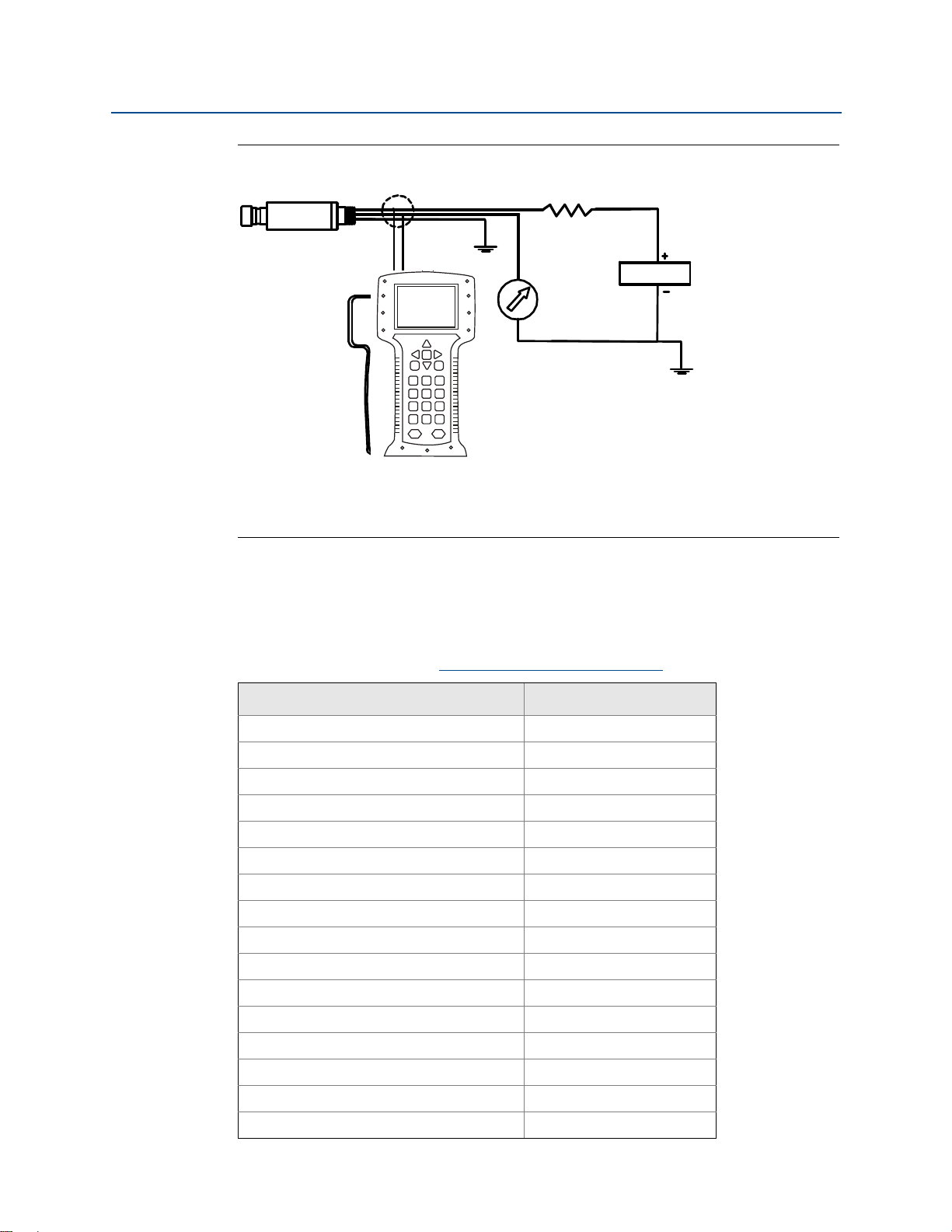
3.5.3 Connect wiring and power up
Wiring
To make connections, connect the red lead to the positive terminal of the power supply and
the black lead to the positive terminal of the I/O card on the PLC. Connect the green wire to
panel ground. Keep green ground wire as short as possible to minimize the effects of Radio
Frequency Interference (RFI).
Inductive-based transient protectors with more than 3 mH of inductance can adversely
affect the output of the Rosemount 4600. If your application requires transient protection,
it is recommended that you order a transmitter with the transient protection option
specified.
Installation
29
Page 36

Installation
Aotewell Ltd
www.aotewell.com
Industry Automation
HongKong|UK|China
sales@aotewell.com
+86-755-8660-6182
September 2016
Reference Manual
00809-0100-4022, Rev GA
Figure 3-2. Field Wiring
B
C
A
D
E
F
A. Rosemount 4600
B. R
L > 250 ohm
C. Power supply
D. I/O card
E. PLC
F. Field Communicator
Signal wiring grounding
Do not run signal wiring in conduit or open trays with power wiring, or near heavy electrical
equipment.
Power supply 4–20 mA transmitters
The dc power supply should provide power with less than two percent ripple. Total
resistance load is the sum of resistance from signal leads and the load resistance of the
controller, indicator, and related pieces. Note that the resistance of intrinsic safety barriers,
if used, must be included.
Note
A minimum loop resistance of 250 ohms is required to communicate with a Field
Communicator. If a single power supply is used to power more than one Rosemount 4600,
the power supply and circuitry common to the transmitter, should not have more than
20 ohms of impedance at 1200 Hz.
30
Installation
Page 37

Reference Manual
1355
11.25
1000
500
0
20
30
42.4
Operating
Regio n
Voltage (V dc)
Aotewell Ltd
www.aotewell.com
Industry Automation
HongKong|UK|China
sales@aotewell.com
+86-755-8660-6182
00809-0100-4022, Rev GA
Figure 3-3. Power Supply Load Limitations, 4–20 mA Transmitters
Maximum field loop Resistance = 43.5 * (Power Supply Voltage - 11.25)
Load (Ohms)
*Communication requires a minimum loop resistance of 250 ohms.
Surges/transients
The transmitter will withstand electrical transients of the energy level usually encountered
in static discharges or induced switching transients. However, high-energy transients, such
as those induced in wiring from nearby lightning strikes, can damage the transmitter.
Installation
September 2016
Optional transient protection
Transient protection can be ordered as a factory installed option (Option Code T1 in the
transmitter model number). Transient protection can not be added to units ordered
without the T1 option.
3.5.4 Zero the transmitter
Performing a zero adjustment is a recommended step for sealed gauge transmitters.
Note
Do not re-zero absolute transmitters.
Re-zeroing the transmitter allows for a single point adjustment to compensate for any
mounting position and sealed gauge effects. This can be done with a zero trim (See “Sensor
trim” on page 40), 4-20 mA rerange or with the zero and span adjustments.
Installation
31
Page 38

Installation
Aotewell Ltd
www.aotewell.com
Industry Automation
HongKong|UK|China
sales@aotewell.com
+86-755-8660-6182
September 2016
3.5.5 Re-zeroing
Reference Manual
00809-0100-4022, Rev GA
Fast Keys
1, 3, 3, 2
Field Communicator
4mA rerange
1. Vent the transmitter.
2. Follow the HART Fast Key sequence shown.
3. Select OK after the control is set to manual (see “Setting the loop to manual” on
page 4).
4. Select 1 to set the 4 mA point.
5. Select OK to set the new 4 mA point.
6. Select 1 to set the vented pressure as the new 4 mA point.
7. Select 3 to exit the screen.
8. Select OK to acknowledge that the loop can be returned to automatic control.
Using the transmitter zero adjustment target
1. Vent the transmitter.
2. Set the 4 mA point by touching the magnetic end of the provided adjustment tool
to the zero target (Z) on the transmitter. You must maintain contact for at least two
seconds, but no longer than ten seconds for the zero function to activate.
3. Verify that the output is 4 mA.
3.6 Hazardous locations
The Rosemount 4600 Transmitter has an explosion-proof housing. Individual transmitters
are clearly marked with a tag indicating the certifications they carry. See Appendix B:
Product Certifications for additional information.
Note
Once a device labeled with multiple approvals is installed, it should not be reinstalled using
any other approval type(s). Permanently mark the certification label to distinguish the
installed approval type from unused approval types.
32
Installation
Page 39

Reference Manual
Aotewell Ltd
www.aotewell.com
Industry Automation
HongKong|UK|China
sales@aotewell.com
+86-755-8660-6182
00809-0100-4022, Rev GA
3.7 Grounding the transmitter case
Always ground the transmitter case in accordance with national and local electrical codes.
The most effective transmitter case grounding method is a direct connection to earth
ground with minimal impedance. Methods for grounding the transmitter case include:
Internal Ground Connection: The green lead provides the internal ground
connection, and is standard on all Rosemount 4600 Transmitters.
External Ground Assembly: This assembly is included with the optional transient
protection (Option Code T1). The External Ground Assembly can also be ordered
with the transmitter (Option Code D4), or as a spare part (4600-0113-0001).
Note
Grounding the transmitter case using the threaded electrical or process connections may
not provide a sufficient ground. The transient protection (Option Code T1) will not provide
transient protection unless the transmitter case is properly grounded. Use the above
guidelines to ground the transmitter case. Do not run transient protection ground wire with
signal wiring; the ground wire may carry excessive current if a lightning strike occurs.
Installation
September 2016
Installation
33
Page 40

Installation
Aotewell Ltd
www.aotewell.com
Industry Automation
HongKong|UK|China
sales@aotewell.com
+86-755-8660-6182
September 2016
Reference Manual
00809-0100-4022, Rev GA
34
Installation
Page 41

Reference Manual
Aotewell Ltd
www.aotewell.com
Industry Automation
HongKong|UK|China
sales@aotewell.com
+86-755-8660-6182
00809-0100-4022, Rev GA
Operation and Maintenance
September 2016
Section 4 Operation and Maintenance
Overview . . . . . . . . . . . . . . . . . . . . . . . . . . . . . . . . . . . . . . . . . . . . . . . . . . . . . . . . . . . . . . .page 35
Calibration for HART
Sensor trim . . . . . . . . . . . . . . . . . . . . . . . . . . . . . . . . . . . . . . . . . . . . . . . . . . . . . . . . . . . . .page 40
Recall factory trim . . . . . . . . . . . . . . . . . . . . . . . . . . . . . . . . . . . . . . . . . . . . . . . . . . . . . . .page 43
Analog output trim . . . . . . . . . . . . . . . . . . . . . . . . . . . . . . . . . . . . . . . . . . . . . . . . . . . . . .page 44
®
protocol . . . . . . . . . . . . . . . . . . . . . . . . . . . . . . . . . . . . . . . . . . . .page 35
4.1 Overview
This section contains information on operation and maintenance of the Rosemount™ 4600
Oil & Gas Pressure Transmitter.
Field Communicator and AMS
maintenance functions. For convenience, Field Communicator Fast Key sequences are
labeled “Fast Keys” for each software function below the appropriate headings.
™
Device Manger instructions are given to perform
4.2 Calibration for HART® protocol
Calibrating a transmitter may include the following procedures:
Rerange: Sets the 4 and 20 mA points at required pressures.
Sensor Trim: Adjusts the position of the factory characterization curve to optimize
performance over a specified pressure range, or to adjust for mounting effects.
Analog Output Trim: Adjusts the analog output to match the plant standard or the
control loop.
Operation and Maintenance
The Rosemount 4600 uses a microprocessor that contains information about the sensor’s
specific characteristics in response to pressure and temperature inputs. A smart transmitter
compensates for these sensor variations. The process of generating the sensor performance
profile is called factory characterization. Factory characterization also provides the ability to
readjust the 4 and 20 mA points without applying pressure to the transmitter.
Trim and rerange functions differ significantly. Reranging sets analog output to the selected
upper and lower range points and can be done with or without an applied pressure.
Reranging does not change the factory characterization curve stored in the microprocessor.
Sensor trimming requires an accurate pressure input and adds additional compensation
that adjusts the position of the factory characterization curve to optimize performance over
a specific pressure range.
Note
Sensor trimming adjusts the position of the factory characterization curve. It is possible to
degrade performance of the transmitter if the trim is done improperly or with inaccurate
equipment.
35
Page 42

Operation and Maintenance
Aotewell Ltd
www.aotewell.com
Industry Automation
HongKong|UK|China
sales@aotewell.com
+86-755-8660-6182
September 2016
Reference Manual
00809-0100-4022, Rev GA
Table 4-1. Recommended Calibration Tasks
Tra ns mitte r Bench calibration tasks Field calibration tasks
Rosemount 4600G
Rosemount 4600A
1.Set output configuration parameters:
a. Set the range points.
b. Set the output units.
c. Set the output type.
d. Set the damping value.
2.Optional: Perform a full sensor trim if
equipment available (accurate absolute
pressure source required), otherwise perform
the low trim value section of the full sensor trim
procedure.
3.Optional: Perform an analog output trim
(Accurate multimeter required).
1.Reconfigure parameters if necessary.
2.Perform low trim value section of the full
sensor trim procedure to correct for
mounting position effects.
4.2.1 Calibration overview
Complete calibration of the Rosemount 4600 involves the following tasks:
Configure the output parameters
Set Process Variable Units (page 9)
Rerange (page 9)
Set Damping (page 11)
Calibrate the sensor
Full Trim (page 42)
Zero Trim (page 41)
Calibrate the 4–20 mA output
4–20 mA Output Trim (page 44); or
4–20 mA Output Trim Using Other Scale (page 45)
Figure 4-1 on page 37 illustrates Rosemount 4600 data flow. Data flow can be summarized
in four major steps:
1. A change in pressure is measured by a change in the sensor output (Sensor Signal).
2. The sensor signal is converted to a digital format that is understood by the
microprocessor (Analog-to-Digital Signal Conversion).
3. Corrections are performed in the microprocessor to obtain a digital representation
of the process input (Digital PV).
36
4. The Digital PV is converted to an analog value (Digital-to-Analog Signal
Conversion).
Figure 4-1 also identifies the approximate transmitter location for each calibration task.
Data flows from left to right, and a parameter change affects all values to the right of the
changed parameter.
Operation and Maintenance
Page 43

Reference Manual
F
E
A
C
I
H
4600: PT-4763
1 á Device Setup
Online
2 PV 1000 PSI
3 AO 20.00 mA
4 LRV 0.00 PSI
5 URV 1000 PSI
B
G
D
TRANSMITTER RANGED 0 TO 1000 PSI
Aotewell Ltd
www.aotewell.com
Industry Automation
HongKong|UK|China
sales@aotewell.com
+86-755-8660-6182
00809-0100-4022, Rev GA
Not all calibration procedures should be performed for each Rosemount 4600. Some
procedures are appropriate for bench calibration, but should not be performed during field
calibration. Ta b le 4 - 1 identifies the recommended calibration procedures for each type of
Rosemount 4600 transmitter for bench or field calibration.
Figure 4-1. Transmitter Data Flow with Calibration Options
Operation and Maintenance
September 2016
A. Sensor
B. Input pressure
C. Input device
D. Field Communicator
E. Microprocessor digital PV
F. Transmitter electronics module
G. Analog output
H.20 mA
I. Output device
Note
Value on PV line should equal the input pressure. Value on AO line should equal the output
device reading.
Operation and Maintenance
37
Page 44

1. Process Variable
2. Diagnostics and
Service
3. Basic Setup
4. Detailed Setup
5. Review Menus
1. Date
2. Descriptor
3. Message
4. Write protect
5. Conf Write Protect
6. Model
7. Model Number 1
8. Model Number II
9. Model Number III
1. Sensors
2. Signal
Condition
3. Output
Condition
4. Device
Information
1. # of diap. seals
2. Seal type
3. Seal fill fluid
4. RS isoltr matl
1.Field Device Info
2.Sensor Information
3.Self Test
4.Diaphragm Seal Info
1.Tag
2. Date
3. Descriptor
4. Message
5. Model
6. Model Number I
7. Model Number II
8. Model Number III
9. Write protect
1. Poll addr
2. Num req preams
3. Burst mode
4. Burst option
1.Press Alert
2.Temp Alert
3.Config Press Alert
4.Config Temp Alert
1. Meas typ
2. Module config type
3. Isoltr matl
4. Fill fluid
5. Process Connector
6. Process Conn Matl
7. O ring matl
8. Drain vent matl
1.Temp Hiu Alert Val
2.Temp Lo Alert Val
3.Snsr Temp USL
4.Snsr Temp LSL
1. Device Setup
2. PV
3. AO
4. PV URV
1.Temp Hi Alert Val
2.Temp Lo Alert Val
3. Snsr Temp USL
4. Snsr Temp LSL
1. Loop test
2. D/A trim
3. Scaled D/A trim
4. Alarm Direction
1. Press
2. % Range
3. AP
4. Snsr temp
1. Press
2. % Range
3. AO
4. Snsr temp
1. PVis
2. SVis
3. TVis
1. Process Variables
2. Analog Output
3. HART Output
4. Reserved
5. Process Alerts
6. Variable Remapping
1. Process Variables
2. Range Values
3. Unit
4. Xfer fnctn
5. Damp
6. Snsr temp Unit
1. Pressure Sensor
2. Device Temp Sensor
1.Keypad Input
2.Apply Values
1.Tag
2. Unit
3. Range Values
4. Device Information
5. Xfer fnctn
6. Damp
1. Keypad Input
2. Apply Values
1.Test Device
2. Loop Test
3. Calibration
1. Pressure
2. Percent of Range
3. Analog Output
4. Sensor Temp.
1.Status
1. Re-Range
2. Analog Input Trim
3. Sensor Trim
4. Recall fact trim
Aotewell Ltd
www.aotewell.com
Industry Automation
HongKong|UK|China
sales@aotewell.com
+86-755-8660-6182
Operation and Maintenance
September 2016
Figure 4-2. HART Menu Tree
38
Reference Manual
00809-0100-4022, Rev GA
Operation and Maintenance
Page 45

Reference Manual
ReferenceAccuracy()
2
TemperatureEffect()
2
+
0.03 U RL×
Span
------------------------------
1.0+
pe r100 °F
2
-------------------------- -
±
= ±0.515% of span
Stability = ±0.5% of span for 3 years = ±0.0139% of span per month
Cal. Freq.
Req. Performance TPE–()
Stability per Month
---------------------------------------------------------------------- -
1.1% 0.57%–()
0.0139%
------------------------------------------
36 months===
Aotewell Ltd
www.aotewell.com
Industry Automation
HongKong|UK|China
sales@aotewell.com
+86-755-8660-6182
00809-0100-4022, Rev GA
4.2.2 Determining calibration frequency
Calibration frequency can vary greatly depending on the application, performance
requirements, and process conditions. Use the following procedure to determine
calibration frequency that meets the needs of your application.
1. Determine the performance required for your application.
2. Determine the operating conditions.
3. Calculate the Total Probable Error (TPE).
4. Calculate the stability per month.
5. Calculate the calibration frequency.
Sample calculation
1. Determine the performance required for your application.
Required Performance: 1.1% of span
Operation and Maintenance
September 2016
2. Determine the operating conditions.
Transmitter: Rosemount 4600G, Range 4
Calibrated Span: 4000 psig
Ambient Temperature
50 °F
Change:
3. Calculate total probable error (TPE).
TPE = = 0.572% of span
Where:
Reference Accuracy = ± 0.25% of span
Ambient Temperature Effect =
Note
Temperature Effect is specified per 100 °F, divide by 2 for 50 °F temperature change.
4. Calculate the stability per month.
5. Calculate calibration frequency.
Operation and Maintenance
39
Page 46

Operation and Maintenance
Aotewell Ltd
www.aotewell.com
Industry Automation
HongKong|UK|China
sales@aotewell.com
+86-755-8660-6182
September 2016
4.2.3 Selecting a trim procedure
To decide which trim procedure to use, you must first determine whether the analog-to-digital section or the digital-to-analog section of the transmitter electronics need
calibration. Refer to Figure 4-1 and perform the following procedure:
1. Connect a pressure source, a Field Communicator or AMS Device Manger, and a
digital readout device to the transmitter.
2. Establish communication between the transmitter and the Field Communicator.
3. Apply pressure equal to the upper range point pressure.
4. Compare the applied pressure to the Process Variable (PV) line on the Field
Communicator Online Menu or the Primary Variables screen in AMS Device
Manger.
a. If the PV reading does not match the applied pressure (with high-accuracy test
equipment), perform a sensor trim.
5. Compare the Analog Output (AO) line, on the Field Communicator or AMS Device
Manger, to the digital readout device.
Reference Manual
00809-0100-4022, Rev GA
a. If the AO reading does not match the digital readout device (with high-accuracy
test equipment), perform an output trim.
4.3 Sensor trim
Trim the sensor using either full or zero trim functions. Trim functions vary in complexity
and are application-dependent. Both trim functions alter the transmitter’s interpretation of
the input signal.
Zero trim is a single-point adjustment. It is useful for compensating for mounting position
and sealed gauge effects. Since this correction maintains the slope of the characterization
curve, it should not be used in place of a full trim over the full sensor range.
When performing a zero trim, ensure that the transmitter is vented to atmosphere.
Note
Do not perform a zero trim on Rosemount 4600 Absolute Pressure Transmitters. Zero trim
is zero based, and absolute pressure transmitters reference absolute zero. To correct
mounting position effects on a Rosemount 4600 Oil & Gas Transmitter, perform a low trim
within the full sensor trim function. The low trim function provides a “zero” correction
similar to the zero trim function, but it does not require zero-based input.
Full trim is a two-point sensor calibration where two end-point pressures are applied, and all
output is linearized between them. Always adjust the low trim value first to establish the
correct offset. Adjustment of the high trim value provides a slope correction to the characterization curve based on the low trim value. The factory-established characterization curve
is not changed by this procedure. The trim values allow you to optimize performance over
your specified measuring range at the calibration temperature.
40
Operation and Maintenance
Page 47

Reference Manual
Aotewell Ltd
www.aotewell.com
Industry Automation
HongKong|UK|China
sales@aotewell.com
+86-755-8660-6182
00809-0100-4022, Rev GA
4.3.1 Zero Trim
Operation and Maintenance
September 2016
Fast Keys
Note
The transmitter must be within three percent of the span away from zero (for zero-based
spans) in order to calibrate with zero trim function. If the zero reading is not within three
percent of the true zero, the transmitter will require iterative trims to move the zero within
trimmable range.
1, 2, 3, 3, 1
Field Communicator
Calibrate the sensor with a Field Communicator using the zero trim function as follows:
1. Vent the transmitter and attach a Field Communicator to the measurement loop.
2. From the Home screen, follow the Fast Key sequence shown.
3. Follow the commands provided by the Field Communicator to complete the zero
trim adjustment.
AMS Device Manger
1. Right click on the device and select Calibrate, Select Zero trim from the menu.
2. Select Next after setting the control loop to manual.
3. Select Next to acknowledge warning.
4. Select Next after applying appropriate pressure to sensor.
5. Select Next to acknowledge the loop can be returned to automatic control.
6. Select Finish to acknowledge the method is complete.
Operation and Maintenance
41
Page 48

Operation and Maintenance
Aotewell Ltd
www.aotewell.com
Industry Automation
HongKong|UK|China
sales@aotewell.com
+86-755-8660-6182
September 2016
4.3.2 Full trim
Reference Manual
00809-0100-4022, Rev GA
Fast Keys
Note
Use a pressure input source that is at least three times more accurate than the transmitter,
and allow the input pressure to stabilize for ten seconds before entering any values.
1, 2, 3, 3
Field Communicator
To calibrate the sensor with a Field Communicator using the full trim function, perform the
following procedure:
1. Assemble and power the entire calibration system including a transmitter, Field
Communicator, power supply, pressure input source, and readout device.
2. From the Home screen, enter the Fast Key sequence shown.
3. Select 2: Lower sensor trim.
Note
Select pressure input values so that low and high values are equal to or outside the 4 and
20 mA points. Do not attempt to obtain reverse output by reversing the high and low
points. The transmitter allows approximately five percent URL deviation from the
characterized curve established at the factory.
4. Follow the commands provided by the Field Communicator to complete the
adjustment of the lower value.
5. Repeat the procedure for the upper value, replacing 2: Lower sensor trim with
3: Upper sensor trim in Step 3.
AMS Device Manger
1. Right click on the device and select Calibrate, then Sensor trim from the menu.
2. Select Lower sensor trim.
3. Select Next after setting the control loop to manual.
4. Select Next after applying appropriate pressure to sensor.
5. Select Next to acknowledge the loop can be returned to automatic control.
6. Select Finish to acknowledge the method is complete.
7. Right click on the device and select Calibrate. Select Sensor trim from the menu
8. Select Upper sensor trim and repeat Step 2-5.
.
42
Operation and Maintenance
Page 49

Reference Manual
Aotewell Ltd
www.aotewell.com
Industry Automation
HongKong|UK|China
sales@aotewell.com
+86-755-8660-6182
00809-0100-4022, Rev GA
4.4 Recall factory trim
The recall factory trim commands allow the restoration of the as-shipped factory settings of
the sensor trim and analog output trim.
4.4.1 Recall factory trim—sensor trim
Operation and Maintenance
September 2016
Fast Keys
This command resets the transmitter sensor trim to the “as shipped” factory settings. The
recall factory trim—sensor trim command can be useful for recovering from an inadvertent
zero trim of an absolute pressure unit or inaccurate pressure source.
1, 2, 3, 4, 1
AMS Device Manger
1. Right click on the device and select Calibrate, then Recall Factory Trim from the
menu
.
2. Select Next after setting the control loop to manual.
3. Select Sensor trim under Trim to r ecall and select Next.
4. Select Next to acknowledge restoration of trim values is complete.
5. Select Next to acknowledge the loop can be returned to automatic control.
6. Select Finish to acknowledge the method is complete.
4.4.2 Recall factory trim—analog output
Fast Keys
This command resets the transmitter analog output trim to the “as shipped” factory
settings. The recall factory trim—analog output command can be useful for recovering from
an inadvertent trim, incorrect Plant Standard or faulty meter.
1, 2, 3, 4, 2
Operation and Maintenance
AMS Device Manger
1. Right click on the device and select Calibrate, then Recall Factory Trim from the
menu
.
2. Select Next after setting the control loop to manual.
3. Select Analog output trim under Trim to recall and select Next.
4. Select Next to acknowledge restoration of trim values is complete.
5. Select Next to acknowledge the loop can be returned to automatic control.
6. Select Finish to acknowledge the method is complete.
43
Page 50

Operation and Maintenance
Aotewell Ltd
www.aotewell.com
Industry Automation
HongKong|UK|China
sales@aotewell.com
+86-755-8660-6182
September 2016
4.5 Analog output trim
The Analog Output Trim commands allow you to adjust the transmitter’s current output at
the 4 and 20 mA points to match the plant standards. This command adjusts the digital to
analog signal conversion (see Figure 4-1 on page 37).
4.5.1 Digital-to-analog trim
Reference Manual
00809-0100-4022, Rev GA
Fast Keys
1, 2, 3, 2, 1
Field Communicator
To perform a digital-to-analog trim with a Field Communicator, perform the following
procedure.
1. From the Home screen, enter the Fast Key sequence shown. Select OK after setting
the control loop to manual, see “Setting the loop to manual” on page 4.
2. Connect an accurate reference ammeter to the transmitter at the Connect Reference
Meter prompt. Connect in series with the signal loop, or shunt power through the
reference meter at some point.
3. Select OK after connecting the reference meter.
4. Select OK at the Setting Fld Dev Output To 4 MA prompt. The transmitter outputs
4.0 mA.
5. Record the actual value from the reference meter, and enter it at the Enter Meter
Value prompt. The Field Communicator prompts you to verify whether or not the
output value equals the value on the reference meter.
6. Select 1: Yes, if the reference meter value equals the transmitter output value, or
2: No if it does not.
44
a. If 1 is selected: Yes, proceed to Step 7.
b. If 2 is selected: No, repeat Step 5.
7. Select OK at the Setting Fld Dev Output To 20 MA prompt, and repeat Step 5 and 6
until the reference meter value equals the transmitter output value.
8. Select OK after the control loop is returned to automatic control.
Operation and Maintenance
Page 51

Reference Manual
Aotewell Ltd
www.aotewell.com
Industry Automation
HongKong|UK|China
sales@aotewell.com
+86-755-8660-6182
00809-0100-4022, Rev GA
AMS Device Manger
1. Right click on the device and select Calibrate, then D/A Trim from the menu.
2. Select Next after setting the control loop to manual.
3. Select Next after connecting the reference meter.
4. Select Next at the Setting fld dev output to 4mA screen.
5. Record the actual value from the reference meter, and enter it at the Enter meter
6. Select Yes , if the reference meter value equals the transmitter output value, or No if
a. If Yes is selected, proceed to Step 7.
b. If No is selected, repeat Step 5.
7. Select Next at the Setting fld dev output to 20 mA screen.
Operation and Maintenance
September 2016
value screen and select Next.
it does not. Select Next.
8. Repeat Step 5 - 6 until the reference meter equals the transmitter output value.
9. Select Next to acknowledge the loop can be returned to automatic control.
10. Select Finish to acknowledge the method is complete.
4.5.2 Digital-to-analog trim using alternate scale
Fast Keys
The Scaled D/A Trim command matches the 4 and 20 mA points to a user selectable
reference scale other than 4 and 20 mA (e.g. 1 to 5 volts if measuring across a 250 ohm
load, or 0 to 100 percent if measuring from a Distributed Control System [DCS]) . To perform
a scaled D/A trim, connect an accurate reference meter to the transmitter and trim the
output signal to scale, as outlined in the Output Trim procedure.
Note
Use a precision resistor for optimum accuracy. If you add a resistor to the loop, ensure the
power supply is sufficient to power the transmitter to a 20 mA output with additional loop
resistance.
1, 2, 3, 2, 2
Operation and Maintenance
45
Page 52

Operation and Maintenance
Aotewell Ltd
www.aotewell.com
Industry Automation
HongKong|UK|China
sales@aotewell.com
+86-755-8660-6182
September 2016
AMS Device Manger
Right click on the device and choose Calibrate then Scaled D/A trim from the menu.
1. Select Next after setting the control loop to manual.
2. Select Change to change scale, select Next.
3. Enter Set scale-Lo output value, select Next.
4. Enter Set scale-Hi output value, select Next.
5. Select Next to proceed with Trim.
6. Select Next after connecting the reference meter.
7. Select Next at the Setting fld dev output to 4 mA screen.
8. Record the actual value from the reference meter, and enter it at the Enter meter
value screen and select Next.
Reference Manual
00809-0100-4022, Rev GA
9. Select Yes , if the reference meter value equals the transmitter output value, or No if
it does not. Select Next.
a. If Yes is selected, proceed to Step 10.
b. If No is selected, repeat Step 8.
10. Select Next at the Setting fld dev output to 20 mA screen.
11. Repeat steps 8 - 9 until the reference meter equals the transmitter output value.
12. Select Next to acknowledge the loop can be returned to automatic control.
13. Select Finish to acknowledge the method is complete.
46
Operation and Maintenance
Page 53

Reference Manual
Aotewell Ltd
www.aotewell.com
Industry Automation
HongKong|UK|China
sales@aotewell.com
+86-755-8660-6182
00809-0100-4022, Rev GA
Section 5 Troubleshooting
Overview . . . . . . . . . . . . . . . . . . . . . . . . . . . . . . . . . . . . . . . . . . . . . . . . . . . . . . . . . . . . . . . . page 47
Safety messages . . . . . . . . . . . . . . . . . . . . . . . . . . . . . . . . . . . . . . . . . . . . . . . . . . . . . . . . . . page 47
5.1 Overview
Ta bl e 5 - 1 provides summarized maintenance and troubleshooting suggestions for the most
common operating problems.
If you suspect malfunction despite the absence of any diagnostic messages on the Field
Communicator display, follow the procedures described here to verify that transmitter
hardware and process connections are in good working order. Always deal with the most
likely checkpoints first.
Troubleshooting
September 2016
5.2 Safety messages
Procedures and instructions in this section may require special precautions to ensure the
safety of the personnel performing the operations. Information that raises potential safety
issues is indicated by a warning symbol ( ). Refer to the following safety messages before
performing an operation preceded by this symbol.
Transmitters located in hazardous areas should be installed in accordance with local
codes and requirements for that area.
Use appropriately rated Ex adapters, blanking elements, and glands during
installation.
Keep process insulation at least 1-in. [25 mm] from transmitter connection.
Static electricity can damage sensitive components.
Observe safe handling precautions for static-sensitive components.
Troubleshooting
47
Page 54

Troubleshooting
Aotewell Ltd
www.aotewell.com
Industry Automation
HongKong|UK|China
sales@aotewell.com
+86-755-8660-6182
September 2016
Reference Manual
00809-0100-4022, Rev GA
Table 5-1. Troubleshooting
Symptom Corrective actions
Transmitter milliamp reading is zero Verify power is applied to signal terminals.
Check power wires for reversed polarity.
Verify terminal voltage is 11.25 to 42.4 V dc.
Transmitter Not Communicating with
Field Communicator
Transmitter milliamp reading is low or
high
Transmitter will not respond to changes in
applied pressure
Digital Pressure Variable reading is low or
high
Digital Pressure Variable reading is erratic Check application for faulty equipment in pressure line.
Milliamp reading is erratic Verify power source to transmitter has adequate voltage and current.
HART message reading:
“Brown-out condition detected.”
HART message reading:
“Configuration not update due to
brown-out.”
Verify the output is between 4 and 20 mA or saturation levels.
Verify clean dc Power to transmitter (Max ac noise 0.2 volts peak to peak).
Check loop resistance, 250 Ω minimum (PS voltage -transmitter
voltage/loop current).
Check if unit is addressed properly.
Verify applied pressure.
Verify 4 and 20 mA range points.
Verify output is not in alarm condition.
Verify if 4 – 20 mA output trim is required.
Check test equipment.
Check impulse piping or manifold for blockage.
Verify applied pressure is between the 4 and 20 mA set points.
Verify output is not in alarm condition.
Verify transmitter is not in Loop Test mode.
Check test equipment (verify accuracy).
Check impulse piping for blockage or low fill in wet leg.
Verify transmitter is calibrated properly.
Verify pressure calculations for application.
Verify transmitter is not reacting directly to equipment turning on/off.
Verify damping is set properly for application.
Check for external electrical interference.
Verify transmitter is properly grounded.
Verify shield for twisted pair is only grounded at one end.
Verify power source to transmitter has adequate voltage and current.
Check loop resistance, 250 Ω minimum (PS voltage -transmitter
voltage/loop current).
Cycle power and repeat configuration change.
48
Troubleshooting
Page 55

Reference Manual
Aotewell Ltd
www.aotewell.com
Industry Automation
HongKong|UK|China
sales@aotewell.com
+86-755-8660-6182
00809-0100-4022, Rev GA
5.2.1 Service support
To expedite the return process outside of the United States, contact the nearest Emerson™
Process Management representative.
Within the United States, call the Rosemount National Response Center using the
1-800-654-RSMT (7768) toll-free number. This center, available 24 hours a day, will assist
you with any needed information or materials.
The center will ask for product model and serial numbers, and will provide a Return Material
Authorization (RMA) number. The center will also ask for the process material to which the
product was last exposed.
Individuals who handle products exposed to a hazardous substance can avoid injury if
they are informed of and understand the hazard. If the product being returned was
exposed to a hazardous substance as defined by OSHA, a copy of the required Material
Safety Data Sheet (MSDS) for each hazardous substance identified must be included
with the returned goods.
Troubleshooting
September 2016
Rosemount National Response Center representatives will explain the additional
information and procedures necessary to return goods exposed to hazardous substances.
Troubleshooting
49
Page 56

Troubleshooting
Aotewell Ltd
www.aotewell.com
Industry Automation
HongKong|UK|China
sales@aotewell.com
+86-755-8660-6182
September 2016
Reference Manual
00809-0100-4022, Rev GA
50
Troubleshooting
Page 57

Specification and Reference Data
Aotewell Ltd
www.aotewell.com
Industry Automation
HongKong|UK|China
sales@aotewell.com
+86-755-8660-6182
September 2016
Reference Manual
00809-0100-4022, Rev GA
Appendix A Specification and Reference
Data
Ordering Information . . . . . . . . . . . . . . . . . . . . . . . . . . . . . . . . . . . . . . . . . . . . . . . . . . . . . . page 51
Performance specifications . . . . . . . . . . . . . . . . . . . . . . . . . . . . . . . . . . . . . . . . . . . . . . . . . page 54
Functional specifications . . . . . . . . . . . . . . . . . . . . . . . . . . . . . . . . . . . . . . . . . . . . . . . . . . . page 54
Physical specifications . . . . . . . . . . . . . . . . . . . . . . . . . . . . . . . . . . . . . . . . . . . . . . . . . . . . . page 55
Dimensional drawings . . . . . . . . . . . . . . . . . . . . . . . . . . . . . . . . . . . . . . . . . . . . . . . . . . . . . page 57
A.1 Ordering Information
Table A-1. Rosemount 4600 Oil and Gas Pressure Transmitter Ordering Information
★ The Standard offering represents the most common options.
Model Transmitter type
4600 Oil and gas panel pressure transmitter
Measurement type
GSealed gauge
A Absolute
Pressure range
2 0-20 to 0-150 psi
4 0-125 to 0-5000 psi
5 0-330 to 0-10,000 psi
6 0-660 to 0-20,000 psi (available only with H11)
Isolating diaphragm/process connection materials
2 316L SST
3 Alloy C-276
Process connection style
E09
E11
H11
(2)
(3)
(4)
1
/4–18 NPT female
1
/2–14 NPT female
Coned and threaded, compatible with autoclave type F-250-C
(1)
★
★
★
★
★
★
★
★
★
★
★
Output
A 4-20 mA with digital signal based on HART® protocol
Electrical connection
5A
Specification and Reference Data
1
/2–14 NPT male with 72-in. flying lead
★
★
51
Page 58

Reference Manual
Aotewell Ltd
www.aotewell.com
Industry Automation
HongKong|UK|China
sales@aotewell.com
+86-755-8660-6182
Specification and Reference Data
00809-0100-4022, Rev GA
Table A-1. Rosemount 4600 Oil and Gas Pressure Transmitter Ordering Information
★ The Standard offering represents the most common options.
Options (Include with selected model number)
Software configuration
September 2016
C1 Custom software configuration (CDS required with order)
Alarm limits
C6 Custom alarm and saturation signal levels, high alarm
C7 Custom alarm and saturation signal levels, low alarm
Hardware adjustments
D1 Zero and span adjustments
External ground screw assembly
D4 External ground screw assembly
Product certifications
E1 ATE X Flameproof
E2 INMETRO Flameproof
I1 ATEX Intrinsic Safety
K1 ATEX Flameproof, Intrinsic Safety, Type n (combination of E1, I1, and N1)
N1 ATEX Type n
ND ATEX Dust Ignition-Proof
E5 FM Approval Explosionproof
I5 FM Approval Intrinsic Safety, Non-incendive
K5 FM Approval Explosionproof, Intrinsic Safety, Non-incendive (combination of E5 and I5)
E6 CSA Explosionproof, Division 2
I6 CSA Intrinsic Safety
K6 CSA Explosionproof, Intrinsic Safety, Division 2 (combination of E6 and I6)
EM Technical Regulations Customs Union (EAC) Flameproof
IM Technical Regulations Customs Union (EAC) Intrinsic Safety
KM Technical Regulation Customs Union (EAC) Flameproof and Intrinsic Safety
KA ATEX/ CSA Flameproof and Intrinsic Safety (combination of E1, I1, E6, and I6)
KB FM Approval and CSA Explosionproof and Intrinsic Safety (combination of E5, E6, I5, and I6)
KC FM Approval and ATEX Explosionproof and Intrinsic Safety (combination of E5, E1, I5, and I1)
★
★
★
★
★
★
★
★
★
★
★
★
★
★
★
★
★
★
★
★
★
★
★
Calibration certifications
Q4 Calibration Data Certificate consistent with ISO 104742.1 or EN 10204 2.1
Material traceability certification
Q8 Material Traceability Certification per EN 10204 3.1B
Transient protection
T1 Transient protection
52
★
★
★
Specification and Reference Data
Page 59

Specification and Reference Data
Aotewell Ltd
www.aotewell.com
Industry Automation
HongKong|UK|China
sales@aotewell.com
+86-755-8660-6182
September 2016
Table A-1. Rosemount 4600 Oil and Gas Pressure Transmitter Ordering Information
★ The Standard offering represents the most common options.
Quality certification for safety
00809-0100-4022, Rev GA
Reference Manual
QS Prior-use certificate of FMEDA data
★
Typical model number: 4600 G 4 2 E11 A 5A WR5 D1 K5
1. Materials of Construction comply with recommendations per NACE® MR0175/ISO 15156 for sour oilfield production environments. Environmental
limits apply to certain materials. Consult latest standard for details. Selected materials also conform to NACE MR0103 for sour refining environments.
2. Not available with Pressure Range 6.
3. Not available with Pressure Range 5 or 6.
4. Only available with Pressure Range 5 or 6.
Specification and Reference Data
53
Page 60

Reference Manual
Aotewell Ltd
www.aotewell.com
Industry Automation
HongKong|UK|China
sales@aotewell.com
+86-755-8660-6182
00809-0100-4022, Rev GA
A.2 Specifications
Specification and Reference Data
September 2016
A.2.1 Performance specifications
For zero-based spans, reference conditions, silicone oil fill,
SST materials, 1/2-in. 14 NPT process connections, digital
trim values set to equal range points. Does not include any
error due to the effects of sealed gauge.
Conformance to specification (±3 Sigma)
Technology leadership, advanced manufacturing
techniques and statistical process control ensure
specification conformance to at least ±3 sigma.
Reference accuracy
Includes the effects of terminal based linearity, hysteresis,
and repeatability.
Range 2: ±0.25% of calibrated span from 1:1 to 7.5:1
rangedown
Range 4: ±0.25% of calibrated span from 1:1 to 40:1
rangedown
Range 5: ±0.25% of calibrated span from 1:1 to 30:1
rangedown
Range 6: ±0.25% of calibrated span from 1:1 to 30:1
rangedown
Long term stability
Vibration effect
Less than ±0.1% of URL when tested per the requirements of
IEC 60770.84 pipeline (general and extreme vibration level)
(10-60 Hz 0.21mm peak to peak displacement/60-2000 Hz
3g).
Electromagnetic Compatibility (EMC)
Meet all relevant requirements of EN 61326.
Transient Protection (Option T1)
Meets IEEE C62.41, Category B
6 kV crest (0.5 μs – 100 kHz)
3 kA crest (8 ⫻ 20 microseconds)
6 kV crest (1.2 ⫻ 50 microseconds)
General Specifications:
Response Time: < 1 nanosecond
Peak Surge Current: 5000 amps to housing
Peak Transient Voltage: 100 V dc
Loop Impedance: < 25 ohms
Applicable Standards: IEC61000-4-4, IEC61000-4-5
Note
Calibrations at 68 °F (20 °C) per ASME Z210.1 (ANSI).
0.5% of span for three years under normal operating
conditions
A.2.2 Functional specifications
Table A-2. Range and sensor limits
Range 2 Range 4 Span Range 5 Range 6
Units
min. max. min. max. min. max. min. max.
psi 20 150 125 5,000 330 10,000 660 20,000
MPa 0.14 1.03 125 34.47 2.28 68.95 4.55 137.90
bar 1.38 10.34 125 344.74 22.75 689.48 45.51 1378,95
2
kg/cm
Dynamic performance
500 Milliseconds (response time + dead time)
Ambient temperature effect per 100
±0.03% URL + 1.0% span from 1:1 to maximum turndown
Service
Liquid, gas, and vapor applications
1.41 10.55 125 351.535 23.20 703.07 46.40 1406,14
°F (56 °C)
54
Specification and Reference Data
Page 61

Specification and Reference Data
1355
11.25
1000
500
0
20
30
42.4
Voltage (V dc)
Load (Ohms)
Communication requires a minimum
loop resistance of 250 ohms.
Operating
Regio n
Max. Loop Resistance = 43.5 (Power Supply Voltage – 11.25)
Aotewell Ltd
www.aotewell.com
Industry Automation
HongKong|UK|China
sales@aotewell.com
+86-755-8660-6182
September 2016
Reference Manual
00809-0100-4022, Rev GA
4–20 mA (output code A)
Zero and span adjustment
Zero and span values can be set anywhere within the
range.
Span must be greater than or equal to the minimum
span.
Output
Digital process variable superimposed on 4–20 mA
signal, available to any host that conforms to the HART
protocol.
Power supply
External power supply required. Standard transmitter
(4–20 mA) operates on 11.25 to 42.4 V dc with no load.
Load limitations
Maximum loop resistance is determined by the voltage
level of the external power supply, as described by:
Tur n-o n ti me
Performance within specifications less than 2.5 seconds
after power is applied to the transmitter
Damping
Analog output response to a step input change is
user-selectable from 0.3 to 60 seconds for one time
constant. This software damping is in addition to sensor
module response time.
Failure mode alarm
HART 4-20mA (output code A)
If self-diagnostics detect a gross transmitter failure, the
analog signal will be driven offscale to alert the user.
Rosemount standard and custom alarm levels are
available.
High or low alarm signal is software-selectable.
Alarm configuration
Rosemount
High Alarm: ≥ 21.75 mA
Low Alarm: ≤ 3.75 mA
Custom Level
(1)
High Alarm: 20.2 - 23.0 mA
Low Alarm: 3.6 - 3.8 mA
Overpressure limits
Transmitters withstand the following pressure without
damage:
Range 2: 1,500 psi (103,4 bar)
Range 4: 7,500 psi (517,1 bar)
Range 5: 15,000 psi (1034 bar)
Range 6: 24,000 psi (1655 bar)
Burst pressure limits
Range 2: 11,000 psi (758,4 bar)
Range 4: 11,000 psi (758,4 bar)
Range 5: 26,000 psi (1793 bar)
Range 6: 31,000 psi (2137 bar)
Temperature limits
Ambient
–40 to 185 °F (–40 to 85 °C)
Storage
–50 to 230 °F (–46 to 110 °C)
Process temperature limits
–40 to 200 °F (–40 to 93 °C)
A.2.3 Physical specifications
Electrical connections
1
/2–14 NPT Male, 72-in. flying leads (polyvinyl chloride
insulated #18 AWG copper wire)
Conduit seal
Integral conduit seal meets the requirements of NEC©
section 501.5 (A), 501.5 (B) and 505.16 (B)(1). No
additional conduit seal required.
Process connections
1
/2-14 NPT female (available on Ranges 2 and 4 only)
1
/4–18 NPT female (not available on Range 6)
Autoclave type F-250-C (Pressure relieved
1
thread:
/4 OD high pressure tube 60° cone:
available Range 5 and 6 transmitters only.
9
/16-18 gland
2002
Specification and Reference Data
1. Low alarm must be 0.1 mA less than low saturation and high alarm
must be 0.1 mA greater than high saturation.
55
Page 62

Reference Manual
Aotewell Ltd
www.aotewell.com
Industry Automation
HongKong|UK|China
sales@aotewell.com
+86-755-8660-6182
00809-0100-4022, Rev GA
Specification and Reference Data
September 2016
Process sealing
Reliable dual process seal design meets the requirements
©
2002 section 501.5 (F)(3), 505.16 (E)(3) and API
NEC
14F/14FZ 6.8.2.2. No additional process sealing is required.
Meets the requirements of ISA 12.27.01.
No additional process sealing required.
Process-wetted parts
Process isolating diaphragms
(1)
316L SST
Alloy C-276
Non-wetted parts
Electronics housing
316L SST
NEMA 4X
IP 68, IP 66
Sensor module fill fluid
Silicone
Ordinary locations certifications
As standard, the transmitter has been examined and tested
to determine that the design meets basic electrical,
mechanical, and fire protection requirements by FM, a
nationally recognized testing laboratory (NRTL) as
accredited by the Federal Occupational Safety and Health
Administration (OSHA).
Shipping weights
Range 2 and 4: 1.34 lb. (0.61 kg)
Range 5 and 6: 2.03 lb. (0.92 kg)
1. Materials of Construction meet NACE material recommendations
56
per MR 01-75. Caution is strongly advised when considering the use
of 316L SST isolating diaphragms in sour environments. Although
these diaphragms meet the intent of the standard, it can be jeopardized by chlorine contaminates that are frequently found in sour
process streams.
Specification and Reference Data
Page 63

Specification and Reference Data
A
B
C
D
6.6
(167.6)
1.125 Hex
(28.6)
1.5
(38.1)
Aotewell Ltd
www.aotewell.com
Industry Automation
HongKong|UK|China
sales@aotewell.com
+86-755-8660-6182
September 2016
A.3 Dimensional drawings
Figure A-1. Range 2 and 4
Without T1 ordering option With T1 ordering option
Reference Manual
00809-0100-4022, Rev GA
A
B
7.1
(180.3)
E
1.125 Hex
(28.6)
1.5
(38.1)
D
A.Ground
B. Electrical connection ½–14 NPT
C. Optional ground screw (Ordering option D4)
Specification and Reference Data
D. Process connection
E. Optional ground screw (standard with T1 option)
Dimensions are in inches (millimeters)
57
Page 64

Reference Manual
A
B
C
D
6.7
(169.5)
1.125 Hex
(28.6)
1.87
(47.6)
Aotewell Ltd
www.aotewell.com
Industry Automation
HongKong|UK|China
sales@aotewell.com
+86-755-8660-6182
00809-0100-4022, Rev GA
Figure A-2. Range 5 and 6
Without T1 ordering option With T1 ordering option
Specification and Reference Data
September 2016
A
B
7.17
(182.1)
A.Ground
B. Electrical connection ½–14 NPT
C Optional ground screw (Ordering Option D4)
E
D
1.125 Hex
(28.6)
1.87
(47.6)
D. Optional ground screw (Standard with T1 Option)
E. Process connection
Dimensions are in inches (millimeters)
58
Specification and Reference Data
Page 65

Product Certifications
Aotewell Ltd
www.aotewell.com
Industry Automation
HongKong|UK|China
sales@aotewell.com
+86-755-8660-6182
September 2016
Reference Manual
00809-0100-4022, Rev GA
Appendix B Product Certifications
Rev 1.3
European Directive Information . . . . . . . . . . . . . . . . . . . . . . . . . . . . . . . . . . . . . . . . . . . . . .page 59
Ordinary Location Certification . . . . . . . . . . . . . . . . . . . . . . . . . . . . . . . . . . . . . . . . . . . . . .page 59
Installation drawings . . . . . . . . . . . . . . . . . . . . . . . . . . . . . . . . . . . . . . . . . . . . . . . . . . . . . . page 62
B.1 European Directive Information
A copy of the EU Declaration of Conformity can be found at
the end of the Quick Start Guide. The most recent revision
of the EU Declaration of Conformity can be found at
EmersonProcess.com/Rosemount.
B.2 Ordinary Location Certification
As standard, the transmitter has been examined and tested
to determine that the design meets the basic electrical,
mechanical, and fire protection requirements by a
nationally recognized test laboratory (NRTL) as accredited
by the Federal Occupational Safety and Health
Administration (OSHA).
B.2.1 North America
E5 US Explosionproof (XP) and Dust-Ignitionproof (DIP)
Certificate: 3012302
Standards: FM Class 3600 - 2011; FM Class 3615 -
2006; FM Class 3810 - 2005; NEMA 250 1991; ANSI/ISA-S12.0.01 - 1998;
ANSI/ISA-S12.22.01 - 1998;
ANSI/ISA-60079-0 - 2009;
Markings: Explosionproof for Class I, Division 1,
Groups B, C, and D; Flameproof for Class
1, Zone 1 AEx d IIC T5 (–40 °C to 85 °C);
Dust-ignition proof for Class II and Class III,
Division 1, Groups E, F, and G;
Temperature Code T5 (T
85 °C); Enclosure Type 4X; Conduit seal
not required.
I5 US Intrinsic Safety (IS), Nonincendive (NI)
Certificate: 3012302
Standards: FM Class 3600 - 2011; Class 3610 - 2010;
Class 3611 - 2004; NEMA 250 - 1991;
ANSI/ISA-S12.0.01 - 1998;
ANSI/ISA-S12.22.01 - 1998;
ANSI/ISA-60079-0 - 2009;
ANSI/ISA-60079-11 - 2009
= –40 °C to
amb
Markings: Intrinsically Safe for use in Class I, Division
1, Groups A, B, C, and D; Temperature
Code T4 (–50 °C to 70 °C); Intrinsically
Safe for use in Class I, Zone 0 AEx ia IIC T4
(–50 °C to 70 °C) in accordance with
control drawing 04620-5007;
Nonincendive for Class I, Division 2,
Groups A, B, C, and D when connected in
accordance with Rosemount drawing
04620-5007; Enclosure Type 4X
E6 Canada Explosionproof and Division 2
Certificate: 1384913
Standards: CSA Std C22.2 No. 25-1966;
CSA Std C22.2 No. 30-M1986;
CAN/CSA-C22.2 No. 94-M91;
CSA Std C22.2 No. 142-M1987;
CAN/CSA-C22.2 No. 157-92;
CSA Std C22.2 No. 213-M1987;
CAN/CSA-E79- 0-95; CAN/CSA- E79-1-95;
CAN/CSA- E79-11-95;
ANSI/ISA No. 12.27.01-2011
Markings: Explosionproof for Class I, Division 1,
Groups B, C, and D; Dust-Ignitionproof for
Class II and Class III, Division 1, Groups E, F,
and G; Temperature Code T5 (–50 °C to
40 °C); Explosion-proof for Class 1, Zone 1
Ex d IIC T5 (–20 °C to 40 °C); Suitable for
Class I, Division 2, Groups A, B, C, and D
when installed per Rosemount drawing
04620-5005; Enclosure Type 4X; Conduit
seal not required
I6 Canada Intrinsic Safety
Certificate: 1384913
Standards: CSA Std C22.2 No. 25-1966; CSA Std
C22.2 No. 30-M1986;
CAN/CSA-C22.2 No. 94-M91;
CSA Std C22.2 No. 142-M1987;
CAN/CSA-C22.2 No. 157-92;
CSA Std C22.2 No. 213-M1987;
CAN/CSA-E79- 0-95; CAN/CSA- E79-1-95;
CAN/CSA- E79-11-95;
ANSI/ISA No. 12.27.01-2011
Product Certifications
59
Page 66

Reference Manual
Aotewell Ltd
www.aotewell.com
Industry Automation
HongKong|UK|China
sales@aotewell.com
+86-755-8660-6182
00809-0100-4022, Rev GA
Product Certifications
September 2016
Markings: Intrinsically Safe for use in Class I, Division
1, Groups A, B, C, and D; Temperature
Code T3C (–50 °C to 70 °C); Intrinsically
Safe for use in Class I, Zone 0 Ex ia IIC T4
(–50 °C to 70 °C) when connected in
accordance with Rosemount drawing
04620-5005; Enclosure Type 4X; For
entity parameters see control drawing
04620-5005
B.2.2 Europe
E1 ATEX Flameproof
Certificate: KEMA02ATEX2231X
Standards: EN60079-0:2006; EN60079-1:2007;
EN60079-26:2007
Markings: II 1/2 G Ex d IIC T6 (–40 °C ≤ Ta ≤
+70 °C)
Special Conditions for Safe Use (X):
1. This device contains a thin wall diaphragm.
Installation, maintenance, and use shall take into
account the environmental conditions to which the
diaphragm will be subjected. The manufacturer's
instructions for installation and maintenance shall be
followed in detail to assure safety during its expected
lifetime.
2. The Rosemount 4600 Pressure Transmitter is
provided with a permanently connected
unterminated cable. The free end of the cable shall be
connected using a suitable junction box, e.g. in type
of protection flameproof enclosure “d” or increased
safety “e”.
I1 ATEX Intrinsic Safety
Certificate: Baseefa03ATEX0114X
Standards: EN60079-0:2012+A11:2013,
EN60079-11:2012
Markings: II 1 G Ex ia IIC T4 Ga (–40 °C ≤ T
+70 °C)
Input parameters HART
Voltage Ui 30 V
Current Ii 200 mA
Power P
Capacitance C
Inductance L
i
i
i
Special Condition for Safe Use (X):
1. The equipment with the Transient Protection (T1)
option is not capable of withstanding the 500 V
insulation test required by Clause 6.3.13 of
EN60079-11:2012. This must be taken into account
when installing the equipment.
1.0 W
35 nF
390 μH
N1 ATEX Type n
Certificate: Baseefa03ATEX0115X
Standards: EN60079-0:2012+A11:2013,
EN60079-15:2010
Markings: II 3G Ex nA IIC T5 Gc (–40 °C ≤ T
≤
a
+70 °C)
Ui = 42.4V
Special Condition for Safe Use (X):
1. The equipment with the Transient Protection (T1)
option is not capable of withstanding the 500 V
insulation test required by Clause 6.5.1 of
EN60079-15:2010. This must be taken into account
when installing the equipment.
ND ATEX Dust
Certificate: KEMA02ATEX2231X
Standards: EN60079-0:2006, EN60079-26:2007,
EN61241-0:2006, EN61241-1:2004 +
C1:2006
Markings: II 1 D Ex tD A20 T85 °C (–40 °C ≤ T
≤
a
+70 °C)
Special Conditions for Safe Use (X):
1. This device contains a thin wall diaphragm.
Installation, maintenance, and use shall take into
account the environmental conditions to which the
diaphragm will be subjected. The manufacturer's
instructions for installation and maintenance shall be
followed in detail to assure safety during its expected
lifetime.
2. The Rosemount 4600 is provided with a permanently
connected unterminated cable. The free end of the
cable shall be connected using a suitable junction
box, e.g. in type of protection flameproof enclosure
“d” or increased safety “e”.
≤
a
B.2.3 Brazil
E2 INMETRO Flameproof
Certificate: UL-BR 15.0509X
Standards: ABNT NBR IEC 60079-0, ABNT NBR IEC
60079-1, ABNT NBR IEC 60079-26
Markings: Ex d IIC Ga/Gb, T6(–60 °C ≤ T
T5/T4(–60 °C ≤ T
≤ +80 °C)
a
≤ +70 °C),
a
Special Condition for Safe Use (X):
1. This device contains a thin wall diaphragm.
Installation, maintenance and use shall take into
account the environmental conditions to which the
diaphragm will be subjected. The manufacturer's
instructions for installation and maintenance shall be
followed in detail in order to assure safety during its
expected lifetime.
60
Product Certifications
Page 67

Product Certifications
Aotewell Ltd
www.aotewell.com
Industry Automation
HongKong|UK|China
sales@aotewell.com
+86-755-8660-6182
September 2016
Reference Manual
00809-0100-4022, Rev GA
B.2.4 Technical Regulations Customs Union
(EAC)
EM EAC Flameproof
Certificate: RU C-US.GB05.B.00401
Markings: Ga/Gb Ex d IIC T6…T4 X,
T6(–60 °C ≤ Ta ≤ +70 °C),
T4/T5(–60 °C ≤ T
Special Condition for Safe Use (X):
1. See certificate for special conditions.
IM EAC Intrinsically Safe
Certificate: RU C-US.GB05.B.00401
Markings: 0Ex ia IIC T4 Ga X (–40 °C ≤ T
Special Condition for Safe Use (X):
1. See certificate for special conditions.
≤ +80 °C)
a
≤ +70 °C)
a
B.2.5 Combinations
K1 Combination of E1, I1, and N1
K5 Combination of E5 and I5
K6 Combination of E6 and I6
KA Combination of E1, I1, E6, and I6
KB Combination of E5, I5, I6, and E6
KC Combination of E5, E1, I5, and I1
KM Combination of EM and IM
Product Certifications
61
Page 68

Reference Manual
Aotewell Ltd
www.aotewell.com
Industry Automation
HongKong|UK|China
sales@aotewell.com
+86-755-8660-6182
00809-0100-4022, Rev GA
B.3 Installation drawings
Figure B-1. CSA 04620-5005
Product Certifications
September 2016
62
Product Certifications
Page 69

Product Certifications
Aotewell Ltd
www.aotewell.com
Industry Automation
HongKong|UK|China
sales@aotewell.com
+86-755-8660-6182
September 2016
Reference Manual
00809-0100-4022, Rev GA
Product Certifications
63
Page 70

Reference Manual
Aotewell Ltd
www.aotewell.com
Industry Automation
HongKong|UK|China
sales@aotewell.com
+86-755-8660-6182
00809-0100-4022, Rev GA
Product Certifications
September 2016
64
Product Certifications
Page 71

Product Certifications
Aotewell Ltd
www.aotewell.com
Industry Automation
HongKong|UK|China
sales@aotewell.com
+86-755-8660-6182
September 2016
Reference Manual
00809-0100-4022, Rev GA
Product Certifications
65
Page 72

Reference Manual
Aotewell Ltd
www.aotewell.com
Industry Automation
HongKong|UK|China
sales@aotewell.com
+86-755-8660-6182
00809-0100-4022, Rev GA
Figure B-2. Factory Mutual 04620-5007
Product Certifications
September 2016
66
Product Certifications
Page 73

Product Certifications
Aotewell Ltd
www.aotewell.com
Industry Automation
HongKong|UK|China
sales@aotewell.com
+86-755-8660-6182
September 2016
Reference Manual
00809-0100-4022, Rev GA
Product Certifications
67
Page 74

Reference Manual
Aotewell Ltd
www.aotewell.com
Industry Automation
HongKong|UK|China
sales@aotewell.com
+86-755-8660-6182
00809-0100-4022, Rev GA
Product Certifications
September 2016
68
Product Certifications
Page 75

Product Certifications
Aotewell Ltd
www.aotewell.com
Industry Automation
HongKong|UK|China
sales@aotewell.com
+86-755-8660-6182
September 2016
Reference Manual
00809-0100-4022, Rev GA
Product Certifications
69
Page 76

Reference Manual
Aotewell Ltd
www.aotewell.com
Industry Automation
HongKong|UK|China
sales@aotewell.com
+86-755-8660-6182
00809-0100-4022, Rev GA
Product Certifications
September 2016
70
Product Certifications
Page 77

Reference Manual
Aotewell Ltd
www.aotewell.com
Industry Automation
HongKong|UK|China
sales@aotewell.com
+86-755-8660-6182
00809-0100-4022, Rev GA
Index
Index
September 2016
A
Address
Changing
Alarm . . . . . . . . . . . . . . . . . . . . . . . . . . . . . . . . . . . . . 14
Burst mode values. . . . . . . . . . . . . . . . . . . . . . . . 14
Failure mode values . . . . . . . . . . . . . . . . . . . . . . 12
Level configuration . . . . . . . . . . . . . . . . . . . . . . . 13
Level verification . . . . . . . . . . . . . . . . . . . . . . . . . 15
Multidrop mode values. . . . . . . . . . . . . . . . . . . . 15
Alerts. . . . . . . . . . . . . . . . . . . . . . . . . . . . . . . . . . . . . . 15
Analog output trim. . . . . . . . . . . . . . . . . . . . . . . . . . . 44
. . . . . . . . . . . . . . . . . . . . . . . . . . . . . . . 23
B
Basic setup . . . . . . . . . . . . . . . . . . . . . . . . . . . . . . . . . . .9
Burst mode
Advanced functions
Alarm and saturation values . . . . . . . . . . . . . . . . 14
. . . . . . . . . . . . . . . . . . . . . . 21
C
Calibration . . . . . . . . . . . . . . . . . . . . . . . . . . . . . . . . . 35
Choosing a procedure. . . . . . . . . . . . . . . . . . . . . 40
Frequency, determining . . . . . . . . . . . . . . . . . . . 39
Full trim . . . . . . . . . . . . . . . . . . . . . . . . . . . . . . . . 42
Overview . . . . . . . . . . . . . . . . . . . . . . . . . . . . . . . 36
Recal factory trim . . . . . . . . . . . . . . . . . . . . . . . . 43
Analog output43
Sensor trim43
Sensor trim . . . . . . . . . . . . . . . . . . . . . . . . . . . . . 40
Tasks . . . . . . . . . . . . . . . . . . . . . . . . . . . . . . . . . . 36
Zero trim . . . . . . . . . . . . . . . . . . . . . . . . . . . . . . . 41
Cloning . . . . . . . . . . . . . . . . . . . . . . . . . . . . . . . . . . . . 18
Commissioning
HART protocol
4
AMS
HART Communicator4
Communicator
Model 275
Configuration
Alarm and saturation
Applying a user configuration. . . . . . . . . . . . . . . 20
Cloning . . . . . . . . . . . . . . . . . . . . . . . . . . . . . . . . 18
Data review . . . . . . . . . . . . . . . . . . . . . . . . . . . . . . .6
Recalling . . . . . . . . . . . . . . . . . . . . . . . . . . . . . . . 18
Reusable copy . . . . . . . . . . . . . . . . . . . . . . . . . . . 20
Saving . . . . . . . . . . . . . . . . . . . . . . . . . . . . . . . . . 18
Scaled variable . . . . . . . . . . . . . . . . . . . . . . . . . . 16
Considerations
General
Mechanical . . . . . . . . . . . . . . . . . . . . . . . . . . . . . 26
. . . . . . . . . . . . . . . . . . . . . . . . . . . . . . . .5
. . . . . . . . . . . . . . . . . . . . . 13
. . . . . . . . . . . . . . . . . . . . . . . . . . . . . . . . 26
D
Damping. . . . . . . . . . . . . . . . . . . . . . . . . . . . . . . . . . . .11
Detailed . . . . . . . . . . . . . . . . . . . . . . . . . . . . . . . . . . . .12
Detailed setup . . . . . . . . . . . . . . . . . . . . . . . . . . . . . . .12
Diagnostics and service . . . . . . . . . . . . . . . . . . . . . . . .16
Diagrams
Bench hook-up . . . . . . . . . . . . . . . . . . . . . . . . . . . .4
Field hook-up . . . . . . . . . . . . . . . . . . . . . . . . . . . . .4
Multidrop network . . . . . . . . . . . . . . . . . . . . . . . .22
Typical multidrop network . . . . . . . . . . . . . . . . . .22
Digital to analog trim . . . . . . . . . . . . . . . . . . . . . . . . . .44
Other scale . . . . . . . . . . . . . . . . . . . . . . . . . . . . . .45
Disassembly
Before disassembling . . . . . . . . . . . . . . . . . . . . . .48
Disassembly procedures . . . . . . . . . . . . . . . . . . . . . . .48
F
Failure mode alarm and saturation
. . . . . . . . . . . . . . . . . . . . . . . . . . . . . . . . . .12
Values
Full trim . . . . . . . . . . . . . . . . . . . . . . . . . . . . . . . . . . . .42
G
Grounding . . . . . . . . . . . . . . . . . . . . . . . . . . . . . . . . . .33
External assembly. . . . . . . . . . . . . . . . . . . . . . . . .33
Internal connection . . . . . . . . . . . . . . . . . . . . . . .33
Signal wiring grounding . . . . . . . . . . . . . . . . . . . .30
H
Hazardous locations. . . . . . . . . . . . . . . . . . . . . . . . . . .32
I
Impulse piping . . . . . . . . . . . . . . . . . . . . . . . . . . . . . . .28
Installation . . . . . . . . . . . . . . . . . . . . . . . . . . . . . . . . . .28
HART flowchart. . . . . . . . . . . . . . . . . . . . . . . . . . .27
Mounting . . . . . . . . . . . . . . . . . . . . . . . . . . . . . . .28
Power supply
HART protocol
Power up. . . . . . . . . . . . . . . . . . . . . . . . . . . . . . . .29
Signal wiring grounding . . . . . . . . . . . . . . . . . . . .30
Wiring . . . . . . . . . . . . . . . . . . . . . . . . . . . . . . . . . .29
Introduction . . . . . . . . . . . . . . . . . . . . . . . . . . . . . . . . . .1
. . . . . . . . . . . . . . . . . . . . . . . .30
L
Lightning . . . . . . . . . . . . . . . . . . . . . . . . . . . . . . . . . . .31
Loop
Setting to manual
. . . . . . . . . . . . . . . . . . . . . . . . . .4
Index
v
Page 78

Index
Aotewell Ltd
www.aotewell.com
Industry Automation
HongKong|UK|China
sales@aotewell.com
+86-755-8660-6182
September 2016
Reference Manual
00809-0100-4022, Rev GA
M
Maintenance. . . . . . . . . . . . . . . . . . . . . . . . . . . . . . . . 35
Manual
. . . . . . . . . . . . . . . . . . . . . . . . . . . . . . . . . . .1
Use of
Mechanical considerations . . . . . . . . . . . . . . . . . . . . . 26
Menu tree . . . . . . . . . . . . . . . . . . . . . . . . . . . . . . . . . . . .5
Mounting
Installation . . . . . . . . . . . . . . . . . . . . . . . . . . . . . 28
Multidrop communication . . . . . . . . . . . . . . . . . . . . . 15
Advanced functions . . . . . . . . . . . . . . . . . . . . . . 22
Communicating . . . . . . . . . . . . . . . . . . . . . . . . . 23
Diagram . . . . . . . . . . . . . . . . . . . . . . . . . . . . . . . 22
O
Operation . . . . . . . . . . . . . . . . . . . . . . . . . . . . . . . . . . 35
Output
Process variables. . . . . . . . . . . . . . . . . . . . . . . . . . .7
Recal factory trim . . . . . . . . . . . . . . . . . . . . . . . . 43
Sensor temperature . . . . . . . . . . . . . . . . . . . . . . . .7
P
Piping, impulse . . . . . . . . . . . . . . . . . . . . . . . . . . . . . . 28
Power supply
HART protocol. . . . . . . . . . . . . . . . . . . . . . . . . . . 30
Power up. . . . . . . . . . . . . . . . . . . . . . . . . . . . . . . . . . . 29
Load limitations. . . . . . . . . . . . . . . . . . . . . . . . . . 31
Power supply HART protocol . . . . . . . . . . . . . . . 30
Process alerts . . . . . . . . . . . . . . . . . . . . . . . . . . . . . . . 15
Process variables. . . . . . . . . . . . . . . . . . . . . . . . . . . . . . .7
Units . . . . . . . . . . . . . . . . . . . . . . . . . . . . . . . . . . . .9
R
Recall factory trim. . . . . . . . . . . . . . . . . . . . . . . . . . . . 43
Analog output . . . . . . . . . . . . . . . . . . . . . . . . . . . 43
Sensor trim . . . . . . . . . . . . . . . . . . . . . . . . . . . . . 43
Recalling . . . . . . . . . . . . . . . . . . . . . . . . . . . . . . . . . . . 18
Re-mapping . . . . . . . . . . . . . . . . . . . . . . . . . . . . . . . . 16
Rerange. . . . . . . . . . . . . . . . . . . . . . . . . . . . . . . . . . . . . .9
AMS only . . . . . . . . . . . . . . . . . . . . . . . . . . . . . . . 11
HART Communicator only . . . . . . . . . . . . . . . . . 10
Pressure Input Source
With AMS
Pressure input source
With HART Communicator
With local zero and span . . . . . . . . . . . . . . . 10
Reusable copy. . . . . . . . . . . . . . . . . . . . . . . . . . . . . . . 20
. . . . . . . . . . . . . . . . . . . . . . . . . . . 11
. . . . . . . . . . . . . 10
S
Saturation
Burst mode values . . . . . . . . . . . . . . . . . . . . . . . .14
Failure mode values . . . . . . . . . . . . . . . . . . . . . . .12
Level configuration . . . . . . . . . . . . . . . . . . . . . . . .13
Multidrop mode values. . . . . . . . . . . . . . . . . . . . .15
Saving a configuration . . . . . . . . . . . . . . . . . . . . . . . . .18
Scaled variable configuration. . . . . . . . . . . . . . . . . . . .16
Sensor Temperature. . . . . . . . . . . . . . . . . . . . . . . . . . . .8
Sensor temperature . . . . . . . . . . . . . . . . . . . . . . . . . . . .7
Sensor trim . . . . . . . . . . . . . . . . . . . . . . . . . . . . . . . . . .40
Service and Diagnostics . . . . . . . . . . . . . . . . . . . . . . . .16
Service Support . . . . . . . . . . . . . . . . . . . . . . . . . . . . . . .1
Setup
. . . . . . . . . . . . . . . . . . . . . . . . . . . . . . . . . . . .9
Basic
Detailed . . . . . . . . . . . . . . . . . . . . . . . . . . . . . . . .12
Signal wiring grounding . . . . . . . . . . . . . . . . . . . . . . . .30
Surges. . . . . . . . . . . . . . . . . . . . . . . . . . . . . . . . . . . . . .31
T
Tagging . . . . . . . . . . . . . . . . . . . . . . . . . . . . . . . . . . . .26
Transient
Protection . . . . . . . . . . . . . . . . . . . . . . . . . . . . . . .31
Transients. . . . . . . . . . . . . . . . . . . . . . . . . . . . . . . . . . .31
Transmitter functions . . . . . . . . . . . . . . . . . . . . . . . . .35
Trim
Analog output. . . . . . . . . . . . . . . . . . . . . . . . . . . .44
Digital to Analog . . . . . . . . . . . . . . . . . . . . . . . . . .44
Other scale . . . . . . . . . . . . . . . . . . . . . . . . . .45
Full . . . . . . . . . . . . . . . . . . . . . . . . . . . . . . . . . . . .42
Recall factory . . . . . . . . . . . . . . . . . . . . . . . . . . . .43
Analog output . . . . . . . . . . . . . . . . . . . . . . . .43
Sensor trim . . . . . . . . . . . . . . . . . . . . . . . . . .43
Sensor . . . . . . . . . . . . . . . . . . . . . . . . . . . . . . . . . .40
Zero. . . . . . . . . . . . . . . . . . . . . . . . . . . . . . . . . . . .41
Troubleshooting. . . . . . . . . . . . . . . . . . . . . . . . . . . . . .47
U
Units, Process variable . . . . . . . . . . . . . . . . . . . . . . . . . . 9
W
Wiring
Signal wiring grounding
Surges . . . . . . . . . . . . . . . . . . . . . . . . . . . . . . . . . .31
Transients . . . . . . . . . . . . . . . . . . . . . . . . . . . . . . .31
Wiring diagrams
Bench hook-up
Field hook-up . . . . . . . . . . . . . . . . . . . . . . . . . . . . .4
. . . . . . . . . . . . . . . . . . . . . . . . . . . .4
. . . . . . . . . . . . . . . . . . . .30
vi
Z
Zero trim . . . . . . . . . . . . . . . . . . . . . . . . . . . . . . . . . . .41
Index
Page 79

Aotewell Ltd
www.aotewell.com
Industry Automation
HongKong|UK|China
sales@aotewell.com
+86-755-8660-6182
Page 80

Global Headquarters
Aotewell Ltd
www.aotewell.com
Industry Automation
HongKong|UK|China
sales@aotewell.com
+86-755-8660-6182
Emerson Process Management
6021 Innovation Blvd.
Shakopee, MN 55379, USA
+1 800 999 9307 or +1 952 906 8888
+1 952 949 7001
RFQ.RMD-RCC@EmersonProcess.com
North America Regional Office
Emerson Process Management
8200 Market Blvd.
Chanhassen, MN 55317, USA
+1 800 999 9307 or +1 952 906 8888
+1 952 949 7001
RMT-NA.RCCRFQ@Emerson.com
Latin America Regional Office
Emerson Process Management
1300 Concord Terrace, Suite 400
Sunrise, FL 33323, USA
+1 954 846 5030
+1 954 846 5121
RFQ.RMD-RCC@EmersonProcess.com
Reference Manual
00809-0100-4022, Rev GA
September 2016
Europe Regional Office
Emerson Process Management Europe GmbH
Neuhofstrasse 19a P.O. Box 1046
CH 6340 Baar
Switzerland
+41 (0) 41 768 6111
+41 (0) 41 768 6300
RFQ.RMD-RCC@EmersonProcess.com
Asia Pacific Regional Office
Emerson Process Management Asia Pacific Pte Ltd
1 Pandan Crescent
Singapore 128461
+65 6777 8211
+65 6777 0947
Enquiries@AP.EmersonProcess.com
Middle East and Africa Regional Office
Emerson Process Management
Emerson FZE P.O. Box 17033
Jebel Ali Free Zone - South 2
Dubai, United Arab Emirates
+971 4 8118100
+971 4 8865465
RFQ.RMTMEA@Emerson.com
Linkedin.com/company/Emerson-Process-Management
Twitter.com/Rosemount_News
Facebook.com/Rosemount
Youtube.com/user/RosemountMeasurement
Google.com/+RosemountMeasurement
Standard Terms and Conditions of Sale can be found at:
Emerson.com/en-us/pages/Terms-of-Use.aspx
The Emerson logo are trademarks and service marks of Emerson Electric Co.
AMS, Rosemount and the Rosemount logotype are trademarks of Emerson
Process Management
HART is a registered trademark of the FieldComm Group.
NEMA is a registered trademark and service mark of the National Electrical
Manufacturers Association.
NEMA is a registered trademark and service mark of the National Electrical
Manufacturers Association.
All other marks are the property of their respective owners.
© 2016 Emerson Process Management. All rights reserve
 Loading...