

00825-0100-3400, Rev AA
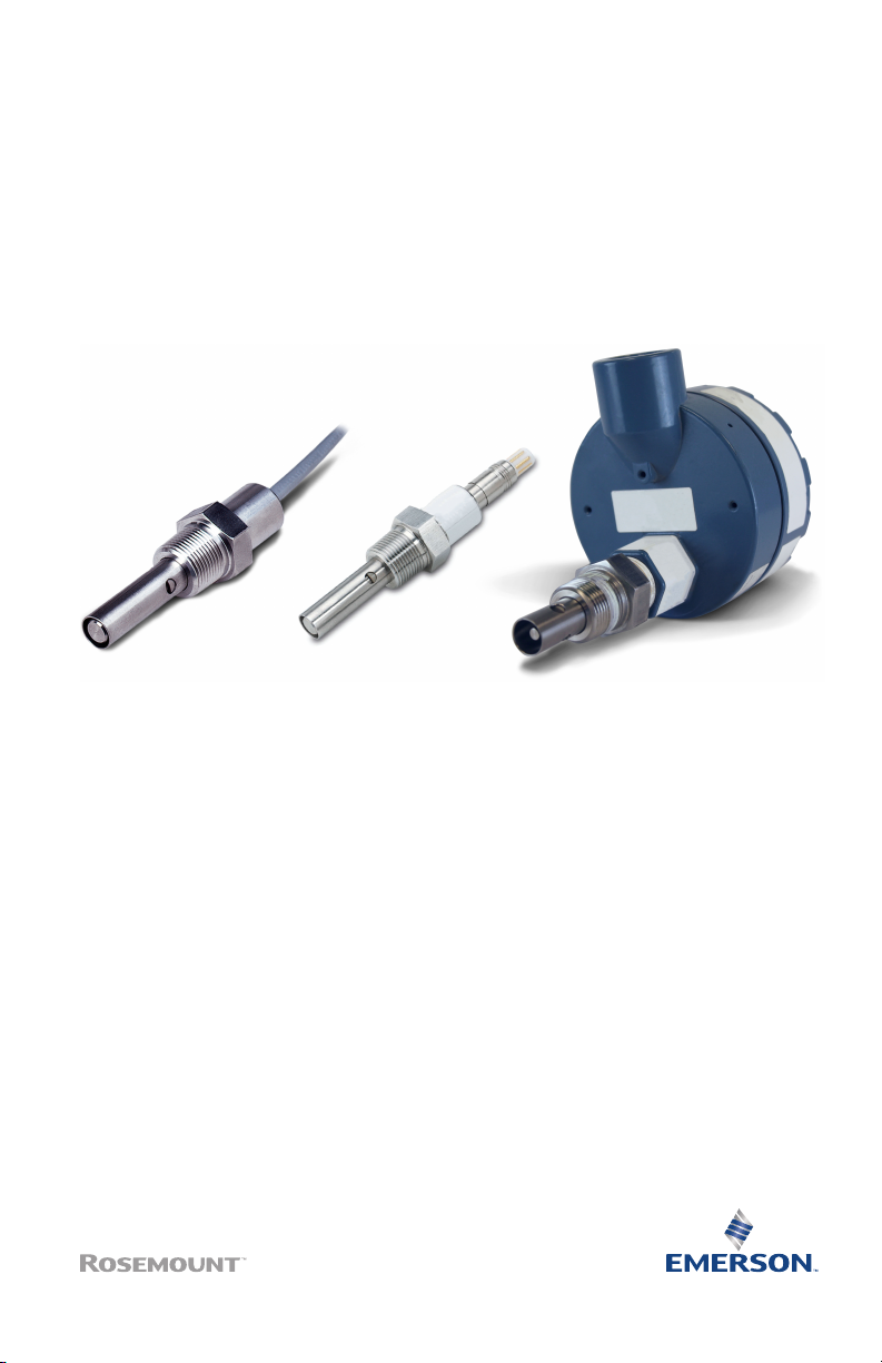
Rosemount™ 400 and 400 VP
Contacting Conductivity Sensors
Quick Start Guide
May 2020

Quick Start Guide May 2020
Essential Instructions
Read this page before proceeding!
Emerson designs, manufactures, and tests its products to meet many national and international
standards. Because these instruments are sophisticated technical products, you must properly install,
use, and maintain them to ensure they continue to operate within their normal specifications. You
must adhere to the following instructions and integrate them into your safety program when
installing, using, and maintaining Emerson's Rosemount products. Failure to follow the proper
instructions may cause any one of the following situations to occur: loss of life, personal injury,
property damage, damage to this instrument, and warranty invalidation.
• Read all instructions prior to installing, operating, and servicing the product.
• If you do not understand any of the instructions, contact your Emerson representative for
clarification.
• Follow all warnings, cautions, and instructions marked on and supplied with the product.
• Inform and educate your personnel in the proper installation, operation, and maintenance of the
product.
• To ensure proper performance, use qualified personnel to install, operate, update, program, and
maintain the product.
• When replacement parts are required, ensure that qualified people use replacement parts
specified by Emerson. Unauthorized parts and procedures can affect the product's performance,
place the safe operation of your process at risk, and VOID YOUR WARRANTY. Look-alike
substitutions may result in fire, electrical hazards, or improper operation.
• Ensure that all equipment doors are closed and protective covers are in place, except when
maintenance is being performed by qualified people, to prevent electrical shock and personal
injury.
Note
The information contained in this document is subject to change without notice.
WARNING
Hazardous area installation
Installations near flammable liquids or in hazardous area locations must be carefully evaluated by
qualified on site safety personnel.
To secure and maintain intrinsically safe installation, use an appropriate transmitter/safety barrier/
sensor combination. The installation system must be in accordance with the governing approval
agency (FM, CSA, or BASEEFA/CENELEC) hazardous area classification requirements. Consult your
transmitter Reference Manual for details.
Proper installation, operation, and servicing of this sensor in a hazardous area installation are
entirely the operator's responsibility.
WARNING
Physical access
Unauthorized personnel may potentially cause significant damage to and/or misconfiguration of end
users’ equipment. This could be intentional or unintentional and needs to be protected against.
Physical security is an important part of any security program and fundamental to protecting your
system. Restrict physical access by unauthorized personnel to protect end users’ assets. This is true for
all systems used within the facility.
2 Emerson.com/Rosemount

May 2020 Quick Start Guide
Contents
Specifications...............................................................................................................................5
Install the sensor.......................................................................................................................... 7
Calibrate and maintain............................................................................................................... 22
Troubleshoot............................................................................................................................. 27
Accessories................................................................................................................................ 31
Quick Start Guide 3

Quick Start Guide May 2020
4 Emerson.com/Rosemount
May 2020 Quick Start Guide
1 Specifications
Wetted materials
Electrodes Titanium
Insulator Glass filled PEEK
Hex block 316 stainless steel
O-ring EPDM
Temperature range
Standard 32 to 221 °F (0 to 105 °C)
With optional integral junction box 32 to 392 °F (0 to 200 °C)
Maximum pressure
250 psig (1825 kPa [abs])
Vacuum
At 1.6-in. Hg (5.2 kPa), air leakage is less than 0.005 SCFM (0.00014 m3/min.)
Cell constants
0.01, 0.1, and 1.0/cm
Process connection
¾-in. (19.1 mm) male national pipe thread (MNPT)
Cable length
10 ft. (3 m) standard; for longer cable lengths, choose option -60 (integral junction
box) and order interconnecting cable separately; interconnecting VP6 cables sold
separately (see Accessories).
Table 1-1: Weights and Shipping Weights
Rounded up to the nearest 1 lb. or 0.5 kg.
Sensor Weight Shipping weight
Rosemount 400 with
10-ft. (3.1 m) integral
cable
Rosemount 400 with
50-ft. (15.2 m) integral
cable
Rosemount 400VP with
Variopol cable connection
Quick Start Guide 5
1 lb. (0.5 kg) 2 lb. (1.0 kg)
4 lb. (2.0 kg) 5 lb. (2.5 kg)
1 lb. (0.5 kg) 2 lb. (1.0 kg)
Quick Start Guide May 2020
Table 1-1: Weights and Shipping Weights (continued)
Sensor Weight Shipping weight
Rosemount 400 with
integral junction box
3 lb. (1.5 kg) 4 lb. (2.0 kg)
Table 1-2: Flow Cell (24092-02) Specifications
Wetted materials
Body and nut Polycarbonate and polyester
¼-in. (6.4 mm) fittings 316 stainless steel
O-ring Silicone
Process connection
Compression fittings for ¼-in. (6.4 mm) OD tubing
Temperature range
32 to 158 °F (0 to 70 °C)
Maximum pressure
90 psig (722 kPa [abs])
6 Emerson.com/Rosemount
May 2020 Quick Start Guide
2 Install the sensor
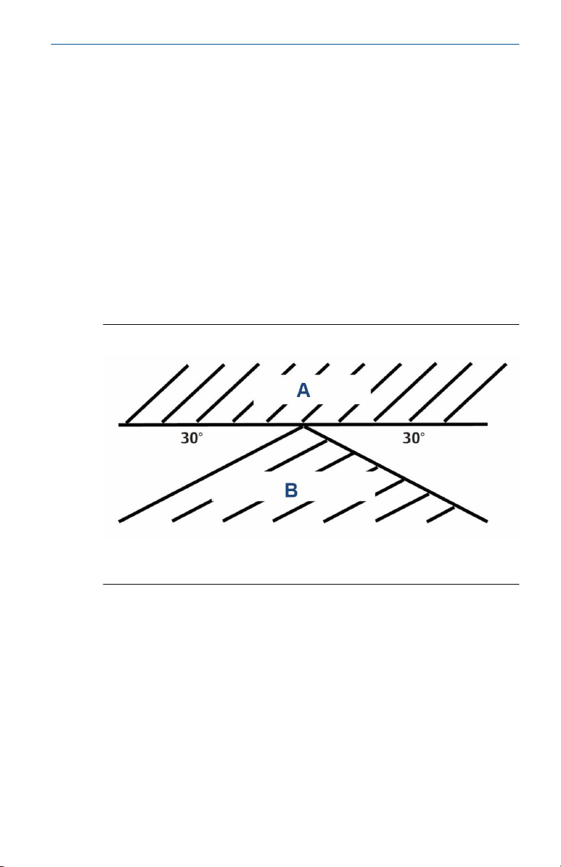
Keep ¼ in. (6.4 mm) clearance between electrodes and piping. The
electrodes must be completely submerged in the process liquid (i.e., to the
level of the threaded connection). See Figure 2-1 to Figure 2-6 for
recommended orientation and installation. You can install Rosemount
400/400VP sensors with 0.1 and 1.0/cm cell constants in ¾-in. (19.1 mm)
pipe tees. You can also install the sensors in 1-in. (25.4 mm) tees with a ¾-in.
(19.1 mm) bushing.
If the sensor is installed in a pipe tee or flow cell with the sample draining to
open atmosphere, bubbles may accumulate on the electrodes. Trapped
bubbles will cause errors. As bubbles accumulate, the conductivity reading
normally drifts down. In the plastic flow cell, bubbles are readily visible. To
control bubble formation, apply a small amount of back pressure to the flow
cell or pipe tee.
Figure 2-1: Sensor Orientation
A. Trapped air
B. Trapped sludge
Quick Start Guide 7
Quick Start Guide May 2020
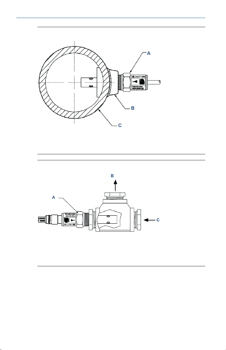
Figure 2-2: Direct Insertion in a Pipe
A. Sensor
B. Weldalet
C. Process piping
Figure 2-3: Insertion in a Pipe Tee
1-in. (25.4 mm) pipe tee with ¾-in. (19.1 mm) bushing shown
A. Sensor
B. Outlet
C. Inlet
8 Emerson.com/Rosemount
May 2020 Quick Start Guide
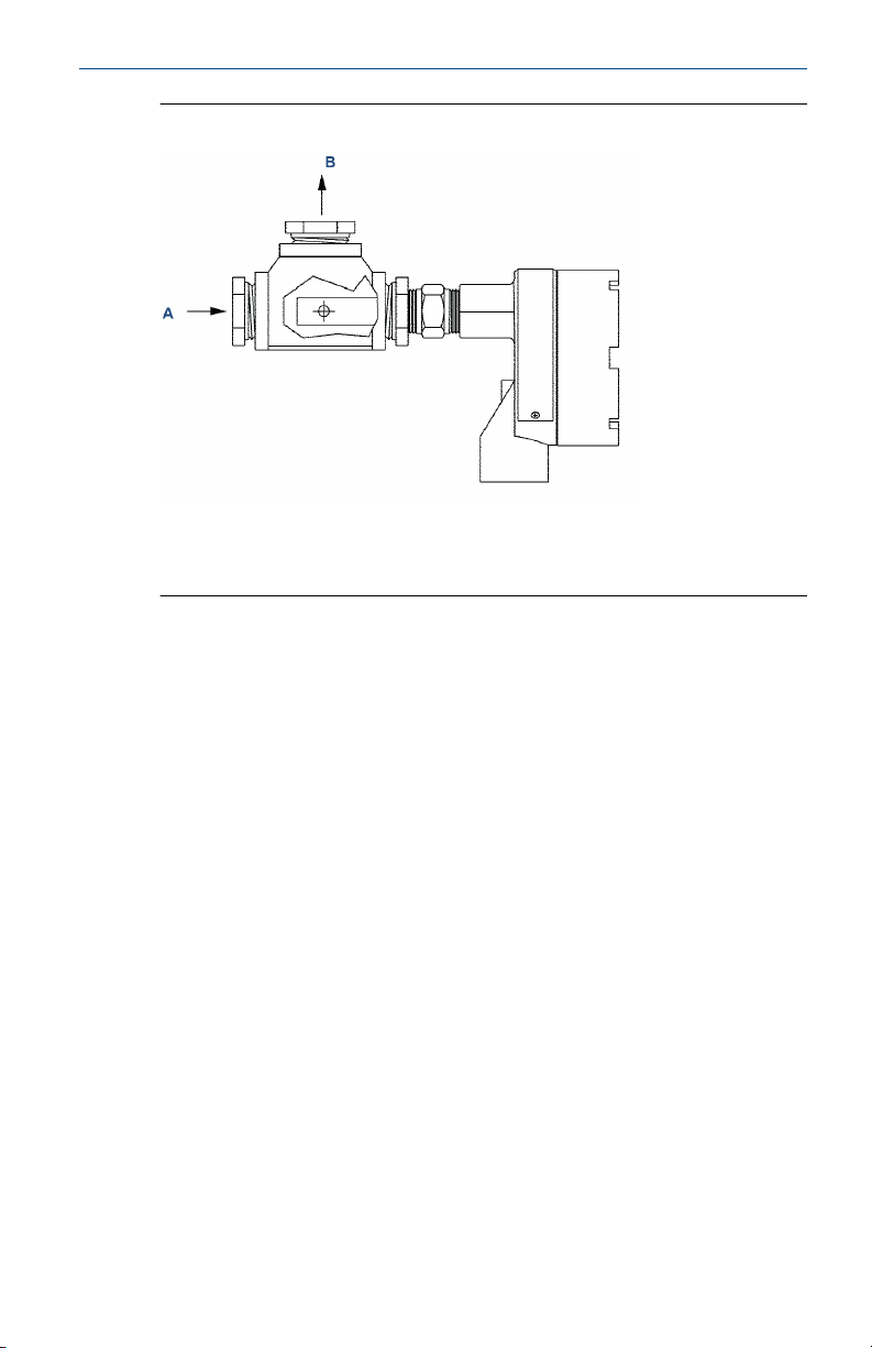
Figure 2-4: Insertion in a Pipe Tee
1-in. pipe tee with ¾-in. bushing shown.
A. Inlet
B. Outlet
Quick Start Guide 9
Quick Start Guide May 2020
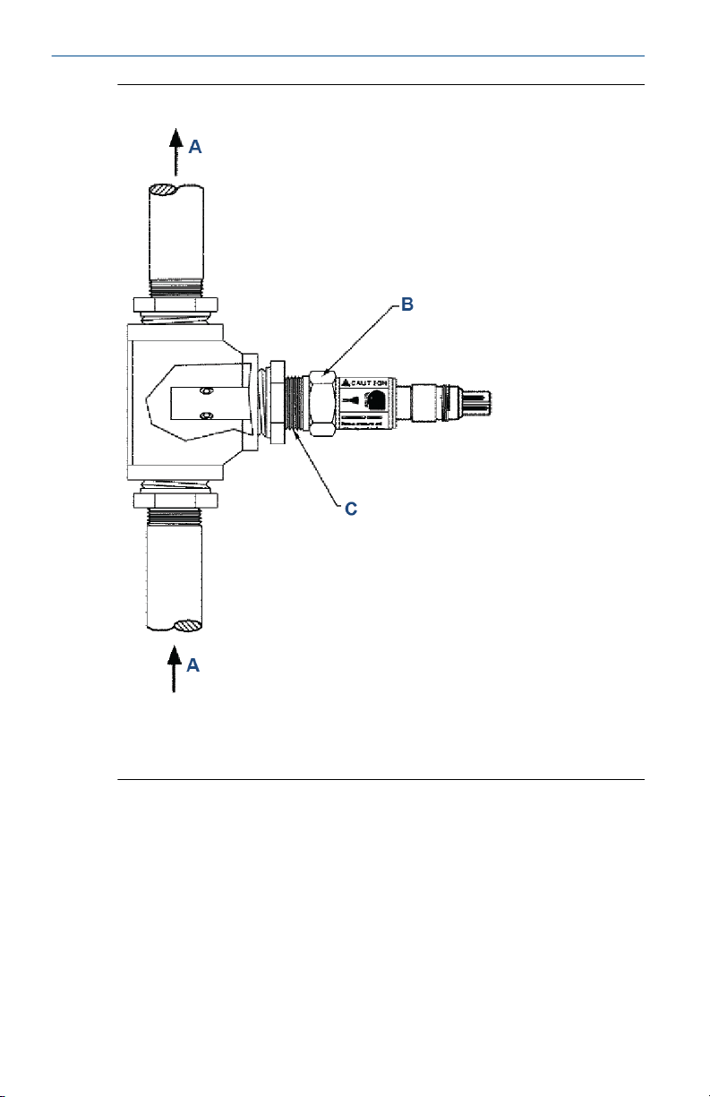
Figure 2-5: Insertion in a Pipe Tee
A. Flow
B. Sensor
C. ¾-in. (19.1 mm) male national pipe thread (MNPT), typical
10 Emerson.com/Rosemount

May 2020 Quick Start Guide
Figure 2-6: Insertion in a Flow Cell (24091-02)
A. Outlet
B. Inlet
Figure 2-7: Rosemount 400 with Integral Cable Connection Dimensional
Drawing
A. Dimension (see Table 2-1)
B. Dimension (see Table 2-1)
C. Dimension (see Table 2-1)
D. ¾-in. (19.1 mm) - 14 national pipe thread (NPT)
E. Equally spaced
Quick Start Guide 11

Quick Start Guide May 2020
Table 2-1: Rosemount 400 with Integral Cable Connection Dimensions
Sensor
configuration
0.01/cm 1.59 40.39 1.98 50.34 4.52 114.8
0.1/cm 0.687 17.45 1.11 28.15 3.65 92.71
1.0/cm 0.667 16.94 1.13 28.70 3.67 93.22
0.01/cm
(with
extended
insertion
length)
0.1/cm
(with
extended
insertion
length)
1.0/cm
(with
extended
insertion
length)
A B C
in. mm in. mm in. mm
1.59 40.39 5.49 139.4 8.00 203.2
0.687 17.45 5.49 139.4 8.00 203.2
0.667 16.94 5.49 139.4 8.00 203.2
12 Emerson.com/Rosemount

May 2020 Quick Start Guide
Figure 2-8: Rosemount 400 with Integral Junction Box Dimensional
Drawing
A. Dimension (see Table 2-2)
B. Dimension (see Table 2-2)
C. Dimension (see Table 2-2)
D. Equally spaced
Table 2-2: Rosemount 400 with Integral Junction Box Dimensions
Sensor
configuration
0.01/cm 1.59 40.39 1.98 50.34 7.41 188.2
0.1/cm 0.687 17.45 1.11 28.15 6.49 164.9
1.0/cm 0.667 16.94 1.13 28.70 6.51 165.4
0.01/cm
(with
extended
insertion
length)
Quick Start Guide 13
A B C
in. mm in. mm in. mm
1.59 40.39 5.49 139.4 10.90 276.9

Quick Start Guide May 2020
Table 2-2: Rosemount 400 with Integral Junction Box Dimensions (continued)
Sensor
configuration
0.1/cm
(with
extended
insertion
length)
1.0/cm
(with
extended
insertion
length)
A B C
in. mm in. mm in. mm
0.687 17,45 5.49 139,4 10.90 276,9
0.667 16.94 5.49 139.4 10.90 276.9
Figure 2-9: Rosemount 400VP with Variopol Cable Connection
A. Dimension (see Table 2-3)
B. Dimension (see Table 2-3)
C. Dimension (see Table 2-3)
D. Dimenson (see Table 2-3)
E. Equally spaced
14 Emerson.com/Rosemount

May 2020 Quick Start Guide
Table 2-3: Rosemount 400VP with Variopol Cable Dimensions
Sensor
configuration
0.01/cm 1.59 40.39 1.98 50.34 4.43 112.5 6.3 160.0
0.1/cm 0.67 17.0 1.10 27.9 3.47 90.4 5.43 137.9
1.0/cm 0.67 17.0 1.10 27.9 3.58 90.9 5.45 138.4
0.01/cm
(with
extended
insertion
length)
0.1/cm (with
extended
insertion
length)
1.0/cm (with
extended
insertion
length)
A B C D
in. mm in. mm in. mm in. mm
1.59 40.39 5.48 139.2 7.91 200.9 9.78 284.4
0.67 17.0 5.48 139.2 7.91 200.9 9.78 284.4
0.67 17.0 5.48 139.2 7.91 200.9 9.78 284.4
Quick Start Guide 15

Quick Start Guide May 2020
2.1 Wire the sensor
For additional wiring information, refer to Emerson.com/
RosemountLiquidAnalysisWiring.
Table 2-4: Wire Color and Connections in Sensor
Color Function
Gray Connects to outer electrode
Clear Coaxial shield for gray wire
Orange Connects to inner electrode
Clear Coaxial shield for orange wire
Red
White with red stripe
White
A. Resistance temperature device (RTD)
B. RTD in
C. RTD sense
D. RTD return
Clear Shield for all RTD lead wires
16 Emerson.com/Rosemount

May 2020 Quick Start Guide
2.2 Wire the sensor to the transmitter
Figure 2-10: Wiring for Rosemount 56, 1056 and 1057 transmitters
Table 2-5: Wiring for Rosemount 56, 1056, and 1057 Transmitters
Terminal number Wire color Connects to
1 White Resistance temperature
2 White/red RTD sense
3 Red RTD in
4 Clear RTD shield
5 N/A 4CT-B
6 N/A 4CT-A
7 Clear Shield 2CT
8 Orange Sensor 2CT-B
9 Clear Shield 2CT
10 Gray Sensor 2CT-A
Quick Start Guide 17
device (RTD) return

Quick Start Guide May 2020
Figure 2-11: Wiring for Rosemount 1066 transmitter
Table 2-6: Wiring for Rosemount 1066 Transmitter
Terminal block Wire color Connects to
TB2 White RTD return
TB2 White/red RTD sense
TB2 Red RTD in
TB2 Clear Shield
TB1 N/A Receive B
TB1 N/A Receive A
TB1 Clear Receive shield
TB1 Gray Drive B
TB1 Orange Drive A
TB1 Clear Drive shield
18 Emerson.com/Rosemount

May 2020 Quick Start Guide
Figure 2-12: Wiring for Rosemount 5081 transmitter
Table 2-7: Wiring for Rosemount 5081 Transmitter
Terminal
number
Wire color Connects to Terminal
number
Wire color Connects to
1 N/A Reserved 9 N/A Drive shield
2 Clear RTD shield 10 Clear Drive
common
3 White RTD return 11 Gray Drive
4 White/red RTD sense 12 N/A N/A
5 Red RTD in 13 N/A N/A
6 N/A Receive shield 14 N/A N/A
7 Clear Receive
common
15 N/A HART®/
FOUNDATION
™
Fieldbus (-)
8 Orange Receive 16 N/A HART/
FOUNDATION
Fieldbus (+)
Quick Start Guide 19

Quick Start Guide May 2020
2.2.1 Wire through junction box
Rosemount 400 Contacting Conductivity Sensors can have an optional
integral junction box mounted on the end of the sensor.
See Figure 2-13 for wiring instructions. If wiring through a remote junction
box (PN 23550-00), wire point-to-point. Use cable 23747-00 (factoryterminated) or 9200275 (raw cable).
Figure 2-13: Sensor-Mounted Junction Box Wiring
Table 2-8: Wiring Sensor to Junction Box
Terminal number Sensor wire color Junction box cable color
1 N/A Clear
2 N/A N/A
3 N/A Clear
4 Gray Gray
5 White White
6 White Red and white/red
7 Orange Orange
8 N/A Clear
9 N/A N/A
20 Emerson.com/Rosemount

May 2020 Quick Start Guide
Note
• The gray sensor wire is connected to the junction box, which makes
electrical contact with the OUTER electrode.
• Terminals in junction box are not numbered. Refer to transmitter wiring
diagram for connections at transmitter.
Figure 2-14: Pin out diagram for Rosemount 400VP with Variopol cable
connection
A. Resistance temperature device (RTD) in
B. RTD return
C. Outer electrode
D. RTD sense
E. Inner electrode
Quick Start Guide 21

Quick Start Guide May 2020
3 Calibrate and maintain
3.1 Calibrating the sensor
Emerson calibrates the sensors at the factory, so they do not need
calibration when they are first placed in service. Simply enter the cell
constant printed on the label into the transmitter.
After a period of service, you may need to calibrate the sensor. For more
information on calibration, refer to the Application Data Sheet.
3.1.1 Calibrate using a standard solution
If using a standard solution, choose one having conductivity in the
recommended operating range for the sensor cell constant.
Procedure
1. Immerse the rinsed sensor in the standard solution and adjust the
transmitter reading to match the conductivity of the standard.
2. Calibrate the sensor.
For an accurate calibration:
a. Choose a calibration standard near the midpoint of the
recommended conductivity range for the sensor.
b. Do not use calibration standards having conductivity less than
100 µS/cm.
c. Turn off automatic temperature compensation in the
transmitter.
d. Use a standard for which the conductivity as a function of
temperature is known.
e. Use a good quality calibrated thermometer with an error rate
less than ±0.1 °C to measure the temperature of the standard.
f. Follow good laboratory practice. Rinse the beaker and sensor
at least twice with standard. Be sure the rinse solution
reaches between the inner and outer electrodes by tapping
and swirling the sensor while it is immersed in the standard.
g. Be sure air bubbles are not trapped between the electrodes.
Place the sensor in the standard and tap and swirl to release
bubbles. Note the reading and repeat. If readings agree, no
trapped bubbles are present. Repeat until two subsequent
readings agree.
22 Emerson.com/Rosemount

May 2020 Quick Start Guide
3.1.2 Calibrate using a reference meter and sensor
Take the following precautions for a successful calibration:
1. If the normal conductivity of the process liquid is less than about
1.0 µS/cm, adjust the conductivity so that it is near the upper end of
the operating range.
The difference between the conductivity measured by the process
and reference meter usually has both a fixed (constant error) and
relative (proportional error) component. Because the cell constant
calibration assumes the error is proportional only, calibration at low
conductivity allows the fixed component to have an outsized
influence on the result.
For example, assume the only difference between reference meter
and process sensor is fixed, and the process sensor always reads
0.002 µS/cm high. If the process sensor is calibrated at 0.100 µS/cm,
the new cell constant will be changed by 0.100/0.102 or two percent.
If the sensor is calibrated at 0.500 µS/cm, the change will be only
0.500/0.502 or 0.4 percent.
Calibration at higher conductivity produces a better result, because it
minimizes the effect of the offset.
2. Orient the sensors so that air bubbles always have an easy escape
path and cannot get trapped between the electrodes.
3. Turn off automatic temperature compensation in the transmitter.
Almost all process conductivity transmitters feature automatic
temperature compensation in which the transmitter applies one of
several temperature correction algorithms to convert the measured
conductivity to the value at a reference temperature, typically 77 °F
(25 °C).
Although temperature correction algorithms are useful for routine
measurements, do not use them during calibration for the following
two reasons:
a. No temperature correction is perfect. If the assumptions
behind the algorithm do not perfectly fit the solution being
measured, the temperature-corrected conductivity will be in
error.
b. If the temperature measurement itself is in error, the
corrected conductivity will be in error.
The purpose of calibrating the sensor is to determine the cell
constant. To minimize the error in the cell constant, eliminate all
sources of avoidable error, e.g., temperature compensation.
4. Keep tubing runs between the sensors short and adjust the sample
flow as high as possible. Short tubing runs and high flow ensure that
Quick Start Guide 23

Quick Start Guide May 2020
the temperature of the liquid does not change as it flows from one
sensor to another.
If the process temperature is appreciably different from ambient,
high flow may not be enough to keep the temperature constant. In
this case, you may need to pump sample at room temperature from
a reservoir through the sensors. Because such a system is likely to be
open to atmosphere, saturate the liquid with air to prevent drift
caused by absorption of atmospheric carbon dioxide.
5. To prevent contamination of low conductivity (< 1 µS/cm) process
liquids, use clean tubing to connect the sensors. To prevent drift
caused desorption of ionic contaminants from tube walls, keep the
sample flow greater than 6 ft./sec (1.8 m/sec).
Procedure
1. Connect the process sensors and reference sensor in series and allow
the process liquid to flow through all sensors.
2. Calibrate the process sensor by adjusting the process transmitter
reading to match the conductivity measured by the reference meter.
See Figure 3-1 for the calibration setup.
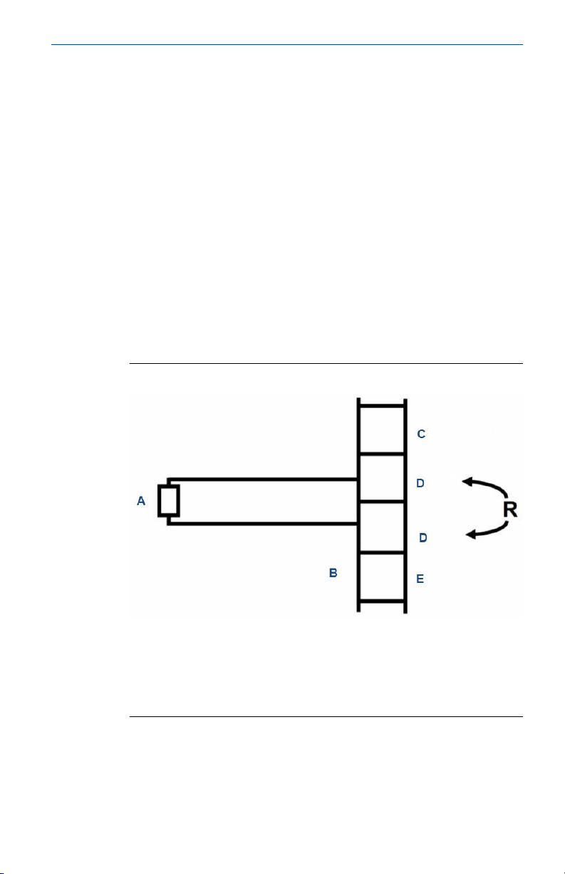
Figure 3-1: In Process Calibration Setup
A. Sample inlet
B. In process sensors
C. Reference sensor
D. Sample output
Note
Figure 3-1 shows two process sensors connected in series with a
reference sensor. The horizontal sensor orientation ensures good
24 Emerson.com/Rosemount

May 2020 Quick Start Guide
circulation of the process liquid past the electrodes. The staircase
orientation provides an escape path for bubbles.
This method is ideal for calibrating the sensors used in low
conductivity water (0.01/cm cell constants), because the calibration
system is closed and cannot be contaminated by atmospheric carbon
dioxide.
3.1.3 Calibrate using a grab sample
Use the grab sample method when it is impractical to remove the sensor for
calibration or to connect a reference sensor to the process line.
Procedure
Take a sample of the process liquid, measuring its conductivity using a
reference instrument and adjusting the reading from the process
transmitter to match the measured conductivity.
Take the sample from a point as close to the process sensor as possible.
Keep temperature compensation turned on. There is likely to be a lag time
between sampling and analysis, so temperature is likely to change.
Be sure the reference and process instruments are using the same
temperature correction algorithm.
Only use grab sample calibration when the conductivity is fairly high.
a. The temperature compensation algorithm will most likely be linear
slope.
b. Confirm that both instruments are using the same temperature
coefficient in the linear slope calculation.
c. If the reference meter does not have automatic temperature
correction, calculate the conductivity at 77 °F (25 °C) using the
equation:
where: C25 = the conductivity at 25 °C
Ct = the conductivity at t °C
α = the temperature coefficient expressed as a decimal fraction
d. Confirm the temperature measurements in both the process and
reference instruments are accurate, ideally to within ±0.5 °C.
e. Follow good laboratory practice when measuring the conductivity of
the grab sample.
• Rinse the beaker and sensor at least twice with sample. Be sure
the rinse solution reaches between the inner and outer
Quick Start Guide 25

Quick Start Guide May 2020
electrodes by tapping and swirling the sensor while it is
immersed in the sample.
• Be sure air bubbles are not trapped in the sensor. Place the sensor
in the sample and tap and swirl to release bubbles. Note the
reading. Then, remove the sensor and return it to the sample.
Tap and swirl again and note the reading. If the two readings
agree, there are no trapped bubbles. If they do not agree,
bubbles are present. Continue the process until two subsequent
readings agree.
• While measuring, do not allow the sensor to touch the sides and,
particularly, the bottom of the beaker. Keep at least ¼ in. (6 mm)
clearance.
f. Be sure to compensate for process conductivity changes that might
have occurred while the grab sample was being tested. Rosemount
conductivity transmitters (Rosemount 1056, 1066, and 56) do this
automatically. They save the value of the process conductivity at the
time the sample was taken and use that value to calculate the new
cell constant when you enter the result of the grab sample test. Older
transmitters do not remember the process conductivity value.
Therefore, you must enter a value adjusted by an amount
proportional to the change in the process conductivity. For example,
suppose the process conductivity is 810 µS/cm when the sample is
taken and 815 µS/cm when the test result is entered. If the grab
sample conductivity is 819 µS/cm, enter (815/810) x 819 or
824 µS/cm.
3.2
26 Emerson.com/Rosemount
Clean the sensor
Procedure
Use a warm detergent solution and a soft brush or pipe cleaner to remove oil
and scale.
You can also use isopropyl alcohol to remove oily films. Avoid using strong
mineral acids to clean conductivity sensors.
May 2020 Quick Start Guide
4 Troubleshoot
4.1 Off-scale reading
Potential cause
Wiring is incorrect.
Recommended action
Verify and correct wiring.
Potential cause
Temperature element is open or shorted.
Recommended action
Check temperature element for open or short circuits.
See Figure 4-1.
Figure 4-1: Checking the Temperature Element
A. Resistance temperature device
B. Terminal strip in sensor junction box
C. Orange
D. Red
E. Gray
Potential cause
Sensor is not in process stream.
Quick Start Guide 27

Quick Start Guide May 2020
Recommended action
Submerge sensor completely in process stream.
Potential cause
Variopol cable is not properly seated.
Recommended action
Loosen connector and reseat.
Potential cause
Sensor has failed.
Recommended action
Perform isolation checks.
See Figure 4-2.
Figure 4-2: Checking the Continuity and Leakage
A. Orange
B. Inner
C. Outer
D. Gray
28 Emerson.com/Rosemount

May 2020 Quick Start Guide
4.2 Noisy reading
Potential cause
Sensor is improperly installed in process stream.
Recommended action
Submerge sensor completely in process stream.
Potential cause
Variopol cable is not properly seated.
Recommended action
Loosen connector and reseat.
4.3 Reading seems wrong (lower or higher than expected)
Potential cause
Bubbles trapped in sensor.
Recommended actions
1. Ensure the sensor is properly oriented in pipe or flow cell.
See Figure 2-1.
2. Apply back pressure to flow cell.
Potential cause
Wrong temperature correction algorithm is being used.
Recommended action
Check that the temperature correction is appropriate for the sample.
See transmitter Reference Manual for more information.
Potential cause
Wrong cell constant.
Recommended action
Verify that the correct cell constant has been entered in the transmitter
and that the cell constant is appropriate for the conductivity of the
sample.
See transmitter Reference Manual.
Quick Start Guide 29

Quick Start Guide May 2020
4.4 Sluggish response
Potential cause
Electrodes are fouled.
Recommended action
Clean electrodes.
Potential cause
Sensor is installed in dead area in piping.
Recommended action
Move sensor to a location more representative of the process liquid.
4.5 Check the temperature element
Procedure
Disconnect leads and measure resistance shown.
The measured resistance should be close to the value in the following table.
Temperature (°C) Resistance in ohms
Pt 100 Pt 1000
0 100.0 1000
10 103.9 1039
20 107.8 1078
30 111.7 1117
40 115.5 1155
50 119.4 1194
See Figure 4-1.
4.6
30 Emerson.com/Rosemount
Check the continuity and leakage
Procedure
Disconnect electrode leads and measure resistance and continuity as shown
in Figure 4-2.
The sensor must be dry when checking resistance between electrode leads.

May 2020 Quick Start Guide
5 Accessories
Part number Description
23747-06 Junction box for a remote cable connection
9200275 Connecting cable, unterminated, specify length
23747-00 Connecting cable, terminated, specify length
24091-02 Low flow cell for Rosemount 400/400VP sensors
05010781899 Conductivity standard SS-6, 200 µS/cm, 32 oz. (0.95 L)
05010797875 Conductivity standard, SS-6A, 200 µS/cm, 1 gal. (3.78 L)
05010782468 Conductivity standard, SS-5, 1000 µS/cm, 32 oz. (0.95 L)
05010783002 Conductivity standard SS-5A, 1000 µS/cm, 1 gal. (3.78 L)
05000705464 Conductivity standard, SS-1, 1409 µS/cm, 32 oz. (0.95 L)
05000709672 Conductivity standard, SS-1A 1409 µS/cm, 1 gal. (3.78 L)
05010782147 Conductivity standard SS-7, 5000 µS/cm, 32 oz. (0.95 L)
05010782026 Conductivity standard SS-7A, 5000 µS/cm, 1 gal. (3.78 L)
23747-06 2.5-ft. (0.8 m) interconnecting VP6 cable
23747-04 6.4-ft. (1.2 m) interconnecting VP6 cable
23747-02 10-ft. (3.0 m) interconnecting VP6 cable
23747-07 15-ft. (4.6 m) interconnecting VP6 cable
23747-08 20-ft. (6.1 m) interconnecting VP6 cable
23747-09 25-ft. (7.6 m) interconnecting VP6 cable
23747-10 30-ft. (9.1 m) interconnecting VP6 cable
23747-03 50-ft. (15.2 m) interconnecting VP6 cable
23747-11 100-ft. (30.5 m) interconnecting VP6 cable
Quick Start Guide 31

GLOBAL HEADQUARTERS
6021 Innovation Blvd.
Shakopee, MN 55379
+1 866 347 3427
+1 952 949 7001
RMTNA.RCCPO@Emerson.com
*00825-0100-3400*
Quick Start Guide
00825-0100-3400, Rev. AA
May 2020
NORTH AMERICA
Emerson Automation Solutions
8200 Market Blvd
Chanhassen, MN 55317
Toll Free +1 800 999 9307
F +1 952 949 7001
RMTNA.RCCPO@Emerson.com
MIDDLE EAST AND AFRICA
Emerson Automation Solutions
Emerson FZE
Jebel Ali Free Zone
Dubai, United Arab Emirates, P.O. Box
17033
+971 4 811 8100
+971 4 886 5465
RMTNA.RCCPO@Emerson.com
LinkedIn.com/company/Emerson-
Automation-Solutions
Twitter.com/rosemount_news
Facebook.com/Rosemount
Youtube.com/RosemountMeasurement
EUROPE
Emerson Automation Solutions
Neuhofstrasse 19a PO Box 1046
CH-6340 Baar
Switzerland
+41 (0) 41 768 6111
+41 (0) 41 768 6300
RMTNA.RCCPO@Emerson.com
ASIA-PACIFIC
Emerson Automation Solutions
1 Pandan Crescent
Singapore 128461
Republic of Singapore
+65 6 777 8211
+65 6 777 0947
RMTNA.RCCPO@Emerson.com
©
2020 Emerson. All rights reserved.
The Emerson logo is a trademark and service
mark of Emerson Electric Co. Rosemount is a
mark of one of the Emerson family of companies.
All other marks are the property of their
respective owners.
 Loading...