

Page 1
Rosemount™ 398R/398RVP
pH/ORP Sensors
Reference Manual
0809-0100-3098
0
Rev. AB
February 2019
Page 2

hasgkas
Page 3
Essential Instructions
Read this page before proceeding!
merson designs, manufactures and tests its products to meet many national and international stan-
E
dards. Because these sensors are sophisticated technical products, you MUST properly install, use,
and maintain them to ensure they continue to operate within their normal specifications. The
following instructions MUST be adhered to and integrated into your safety program when installing,
using, and maintaining Rosemount products. Failure to follow the proper instructions may cause any
one of the following situations to occur: loss of life; personal injury; property damage; damage to this
sensor; and warranty invalidation.
• Read all instructions prior to installing, operating, and servicing the product.
• If you do not understand any of the instructions, contact your Emerson representative for
clarification.
• Follow all warnings, cautions, and instructions marked on and supplied with the product.
• Inform and educate your personnel in the proper installation, operation, and maintenance
of the product.
• Install your equipment as specified in the Installation Instructions of the appropriate
Reference Manual and per applicable local and national codes. Connect all products to
the proper electrical and pressure sources.
• To ensure proper performance, use qualified personnel to install, operate, update,
program, and maintain the product.
• When replacement parts are required, ensure that qualified people use replacement parts
specified by Emerson. Unauthorized parts and procedures can affect the product's
performance, place the safe operation of your process at risk, and VOID YOUR WARRANTY.
Third-party substitutions may result in fire, electrical hazards, or improper operation.
• Ensure that all equipment doors are closed and protective covers are in place, except when
maintenance is being performed by qualified persons, to prevent electrical shock and
personal injury.
The information contained in this document is subject to change without notice.
DANGER
Hazardous Area InstallationN
This sensor is not Intrinsically Safe. or Explosion Proof. Installations near flammable liquids or in hazardous
area locations must be carefully evaluated by qualified on site safety personnel.
To secure and maintain an intrinsically safe installation, an appropriate transmitter/safety barrier/sensor
combi nation must be used. The installation system must be in accordance with the governing approval
agency (FM, CSA or BASEEFA/CENELEC) hazardous area classification requirements. Consult your transmitter instruc tion manual for details.
Proper installation, operation and servicing of this sensor in a Hazardous Area Instal lation is entirely the
responsibility of the user.
CAUTION
Sensor/Process Application Compatibility
The wetted sensor materials may not be compatible with process composition and operating
conditions. Application compatibility is entirely the responsibility of the user.
WARNING
Retractable sensors must not be inserted nor retracted when process pressures are in excess of 64 psig
(542kPa) for option 21 or 35 psig (343 kPa) for option 25.
Page 4

CAUTION
Special Conditions for Safe Use
1. All pH/ORP sensors have a plastic enclosure which must only be cleaned with a damp cloth to avoid the
danger due to a build up of an electrostatic charge.
2. All pH/ORP sensor models are intended to be in contact with the process fluid and may not meet the
500V r.m.s. a.c. test to earth.
his must be taken into consideration at installation.
T
Page 5

Reference Manual Table of Contents
00809-0100-3098 February 2019
Contents
Section 1: Description and Specifications
1.1 Features and Applications....................................................................................1
1.2 Specifications ......................................................................................................2
1.3 Product Certifications..........................................................................................3
1.4 Ordering Information...........................................................................................4
Section 2: Installation
2.1 First Time Installation ..........................................................................................7
2.2 Unpacking and Inspection ...................................................................................8
2.3 Mechanical Installation ........................................................................................8
Section 3: Wiring the Rosemount 398R/398RVP Sensor
3.1 Wiring for Rosemount 398R/398RVP Sensor......................................................15
Section 5: Calibration
5.1 General Information ..........................................................................................27
5.2 Use of Calibration Buffers (Standards) ................................................................27
5.3 Two Point Buffer Calibration...............................................................................28
5.4 pH Standardization............................................................................................28
5.5 ORP Standardization..........................................................................................29
Section 6: Maintenance
6.1 Maintenance......................................................................................................31
6.2 Sensor Removal .................................................................................................31
6.3 Cleaning Procedures - pH Sensors ......................................................................32
6.4 Cleaning Procedures - ORP Sensors ....................................................................34
6.5 Checking the Reference Electrode......................................................................34
6.6 Rejuvenating Reference Electrodes ....................................................................35
6.7 Temperature Element ........................................................................................35
6.8 Sensor Tube Replacement When Used With A Sensor Head Junction Box............36
Section 7: Troubleshooting
7.1 Troubleshooting ................................................................................................39
Section 8: Accessories
8.1 Accessories........................................................................................................43
EC Declaration of Conformity ...............................................................................45
Intrisicallly Safe Sensor Installation Drawing - FM ......................................49
Table of Contents i
Page 6

Table of Contents Reference Manual
February 2019 00809-0100-3098
ii Table of Contents
Page 7
Reference Manual Description and Specifications
00809-0100-3098 February 2019
Section 1: Description and Specifications
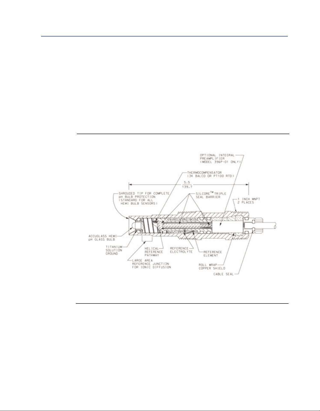
1.1 Features and Applications
Rosemount 398R and 398RVP sensors feature a chemical resistant construction of Tefzel, titanium,
and a TUpH reference junction which is ideal for measuring pH in harsh process liquids. These
sensors can be used to measure pH in sour water strippers, in pulp bleaching towards that use
chlorine dioxide, and in process streams containing a variety of organic solvents. These sensors are
designed for use with a 1-1/4 inch or 1-1/2 inch ball valve.
Figure 1-1: Cross Section Diagram of the TUpH Reference Technology
All TUpH sensors are designed with a large area reference junction, helical reference pathway, and an
AccuGlass pH glass bulb. This sensor technology ensures superior performance while only requiring
minimal maintenance.
Description and Specifications 1
Page 8
Description and Specifications Reference Manual
February 2019 00809-0100-3098
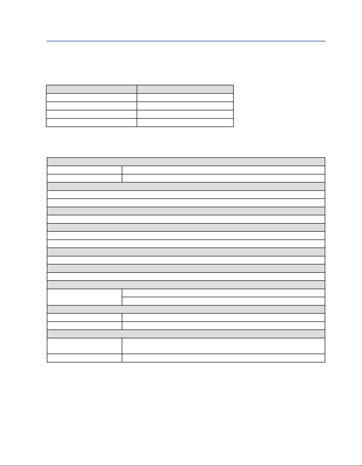
1.2 Specifications
Table 1-1: Percent linearity over pH
pH Range Hemi Bulb
0-2 pH 94%
-12 pH
2
12-13 pH 97%
13-14 pH 92%
Table 1-2: Rosemount 398R-398RVP sensor specifications
Measured Range
pH range 0 to 14 pH, GPHT ACCUGLASS
ORP range -1500 mV to 1500 mV
Maximum Pressure at Retraction or Insertion
64 psig (524 kPa abs) Code 21
35 psig (343 kPa abs) Code 25
Minimum Conductivity
75 μS/cm, nominal 100 μS/cm
Maximum Process Pressure and Temperature
Hemi bulb: 250 psig (1825 kPa abs) at 212°F (100°C)
Flat bulb: 100 psig (790 kPa abs) at 212°F (100°C)
Wetted Materials
Titanium, Tefzel®, glass, platinum (ORP only), and choice of Viton® or Kalrez®
Reference
Permeable Tefzel with secondary helical pathway
Weight/Shipping Weight
Sensor Code 21; 2.0 lb/3.0 lb (.9kg/1.40kg)
Code 25; 3.0 lb/4.0 lb (1.40 kg/1.80kg)
Process Connections
With ball valve 1-1/2 in.
Without ball valve 1 in.
Cable Length
Rosemount 398R Standard 15 ft. Integral Cable; Optional 9.5 inch Cable for wiring to Sensor Head Junction
Boxes
Rosemount 398RVP Must use VP interconnect cable (sold separately)
9%
9
2 Description and Specifications
Page 9

Reference Manual Description and Specifications
00809-0100-3098 February 2019
1.3 Product Certifications
lease see online certificates for further details.
P
IECEx
Sensors with no preamp (pH and ORP) – Ex ia IIC T4 Ga (-20°C ≤ Ta ≤ +60 °C)
Sensors with SMART preamp (398RVP pH only) – Ex ia IIC T4 Ga (-20 °C ≤ Ta ≤ +60 °C)
Per standards IEC60079-0 : 2011, IEC 60079-11 : 2011
ATEX
Sensors without preamp (pH and ORP) – II 1 G Ex ia IIC T4 Ga (-20 °C ≤ Ta ≤ +60 °C)
Sensors with SMART preamp (398RVP pH only ) – II 1 G Ex ia IIC T4 Ga (-20˚C ≤ Ta ≤ +60 °C)
Per standards EN 60079-0: 2012+A11:2013, EN 60079-11:2012
FM
See online FM Certificate of Compliance for applicable sensor options:
Intrinsically Safe for use in Class I, II, and III, Division 1, Groups A, B, C, D, E, F, and G; Temperature
Class T6 Ta = -20 °C to +60 °C
Intrinsically Safe for use in Class I, Zone 0, AEx ia IIC T6 Ta = -20 °C to +60 °C
Nonincendive for use in Class I, Division 2, Groups A, B, C, and D; Temperature Class T6 Ta = -20 °C
to +60 °C
Suitable for use in Class II and III, Division 2, Groups E, F, and G; Temperature Class T6 Ta = -20 °C
to +60 °C Hazardous (Classified) Locations
IS/I,II,III/1/ABCDEFG/T6 Ta = 60°C - 1400332; Entity; I/0/AEx ia IIC/T6 Ta = 60 °C - 1400332; Entity;
NI/I/2/ABCD/T6 Ta = 60 °C; S/II,III/2/EFG/T6 Ta = 60 °C
Per standards 3600:1998, 3610:2010, 3611:2004, 3810:2005
CSA
See online CSA Certificate of Compliance for applicable sensor options:
Sensors with preamp – Intrinsically Safe:
Class I, Division 1, Groups ABCD; Class II, Division 1, Groups EFG; Class III; Class I, Division 2, Groups
ABCD; Ambient temperature rating -20 °C to +60 °C; Ex ia IIC; T6
Sensors without preamp – Intrinsically Safe and Non-Incendive:
Class I, Division 1, Groups ABCD; Class II, Division 1, Groups EFG; Class III; Class I, Division 2,
Groups ABCD; Ex ia IIC; T6; Ambient temperature rating -20 °C to +60 °C: (Simple Apparatus)
Per standards C22.2 No. 0-10, C22.2 No. 0.4-M2004, C22.2 No. 94-M1991, C22.2 No. 142 –
M1987, C22.2 No 157 – M1992, CAN/CSA E60079-0:07, CAN/CSA E60079- 11:02, UL50 11th
Ed, UL508 17th Ed, UL913 7th Ed, UL 60079-0: 2005, UL 60079-11: 2002
Description and Specifications 3
Page 10

Description and Specifications Reference Manual
February 2019 00809-0100-3098
1.4 Ordering Information
Table 1-4: Rosemount 398R ordering information
Model Sensor type
398R pH/ORP Sensor
Measuring Electrode Type
10 pH - GPHT Glass
12 ORP
13 pH - GPHT Flat Glass
Sensor Length
21 21 Inch Titanium Tube
25 36 Inch Titanium Tube
O-ring Material
30 EPDM
31 Viton
32 Kalrez
Transmitter/TC Compatibility
54 Pt-100
Cable Options
_ No Selection
60 9.5 Inch Cable with BNC
61 9.5 Inch Cable without BNC
62 15 ft (4.6 m) Cable without BNC
Typical Model Number: 398R-10-21-30-54-62
(1)
(1)
(2)
1. For use with sensor-head junction boxes.
2. For use with Rosemount 1056, 1057, 1066, 56, and 56 Transmitters.
4 Description and Specifications
Page 11

Reference Manual Description and Specifications
00809-0100-3098 February 2019
Table 1-5: Rosemount 398RVP ordering information
Model Sensor type
398RVP pH/ORP Sensor
easuring Electrode Type
M
0
1
12 ORP
13 pH - GPHR Flat Glass
Sensor Length
21 21 Inch Titanium Tube
25 36 Inch Titanium Tube
O-ring Material
30 EPDM
31 Viton
32 Kalrez
Transmitter/TC Compatibility
50 3K TC
54 Pt-100
55 Pt-100 for SMART Preamplifier
Preamplifier Options
_ No Selection
70 SMART Preamplifier
Typical Model Number: 398RVP-10-25-31-55-70
H - GPHT Glass
p
(1)
(2)
(3)
1. For use with legacy transmitter model 1181. If selected with ORP, the sensor comes without a 3K TC.
2. For use with Rosemount 1056, 1057, 1066, 56, and 5081 transmitters. Must be selected with option 70.
3. Only available with option 55.
Description and Specifications 5
Page 12

Description and Specifications Reference Manual
February 2019 00809-0100-3098
6 Description and Specifications
Page 13

Reference Manual Installation
00809-0100-3098 February 2019
Section 2: Installation
2.1 First Time Installation
For first time installations, using the following guide is recommended:
Variopol Mating Connector Cables (Required for Rosemount 398RVP only)
Choose one:
PN 24281-00, 15 ft cable with mating VP connector
PN 24281-06, 10 ft cable with mating VP connector
Retractable Mounting
A. Choose one (required for all first time installations without ball valves or with 1-1/2 in. ball valve):
PN 23166-00, 1 in. MNPT process connector, Stainless Steel w/EPDM O-ring
PN 23166-01, 1 in. NPT process connector, Titanium w/EPDM O-ring
B. Choose one (Optional; Process Connector O-rings):
PN 9550220, O-ring, Kalrez®, 2-214
PN 9550099, O-ring, Viton®, 2-214
C. Choose one:
PN 23240-00, 1-1/2 in. ball valve assembly, 316 SST (process connector required)
PN 23765-00, 1-1/4 in. ball valve assembly, 316 SST, with graphite packed adapter
Junction Boxes (Optional; Choose either Sensor Head or Remote)
A. Sensor Head Junction Boxes (used with 9.5 in. cable length sensor) - Choose one:
PN 23709-00; includes preamplifier
B. Remote Junction Boxes (used with 15 ft cable length sensor or Rosemount 398RVP) Choose one:
PN 23555-00; includes preamplifier
Extension Cables - Choose one:
PN 23646-01, 11 conductor, shielded, prepped
PN 9200273, 11 conductor, shielded, unprepped
Installation 7
Page 14
Installation Reference Manual
February 2019 00809-0100-3098
2.2 Unpacking and Inspection
Inspect the outside of the carton for any damage. If damage is detected, contact the carrier
immediately. Inspect the instrument and hardware. Make sure all items in the packing list are
resent and in good condition. Notify the factory if any part is missing.
p
Note: If the sensor is to be stored, the protective boot should be filled with either KCl electrolyte
solution or pH 4.0 buffer solution and replaced on sensor tip until ready to use.
Note:Save the original packing cartons and materials as most carriers require proof of damage due
to mishandling, etc. Also, if it is necessary to return the instrument to the factory, you must pack
the instrument in the same manner as it was received. Refer to Section 6.0 for instructions.
WARNING
Glass electrode must be wetted at all times (in storage and in line) to maximize sensor life.
2.3 Mechanical Installation
Both models may be installed through a weldalet or in a pipe tee or “Y”, as shown in Figure 2-2,
when used with a ball valve. Insert the end of the sensor to a depth sufficient to ensure that the
glass bulb is continuously wetted by the process fluid. Each model can also be inserted directly into
the process without the use of a ball valve for appli cations not requiring continuous operation
during sensor maintenance.
CAUTION
Allow sufficient room for safe retraction and insertion of the sensor. Personnel should have room for stable
footing while performing removal or insertion of the sensor.
The sensor must be mounted within 10-90 degrees of the horizontal with the tip pointed
downward. This ensures that the inside surface of the pH-sensitive glass bulb is completely wetted
and that there is a good electrical connection between the bulb and the internal silver/silver
chloride reference electrode. If the retraction version is to be installed without a ball valve follow
the installation procedure for insertion service (Section 2.3.2). Perform the following steps for
sensor installation through a ball valve:
2.3.1 Installation Through Ball Valve
1. Carefully remove the liquid filled rubber boot which protects the glass electrode and keeps
the liquid junction wet during shipping and storage. Discard the liquid and boot. Make
sure the lubricated O-ring is in place in the groove inside the male connector on the sensor
body.
CAUTION
Buffer solution, in the protective boot, may cause skin or eye irritation.
2. With the male connector on the sensor’s body, insert the sensor into the ball valve until it
gently touches the closed valve. The molded electrode guard will protect the glass bulb
from breakage. (extra caution should be taken when inserting the flat glass sensor into
the valve because it does not have an electrode guard).
8 Installation
Page 15
Reference Manual Installation
00809-0100-3098 February 2019
3. Thread the male connector body tightly into the ball valve assembly. DO NOT tighten the
hex nut on the male connector body; doing so would not allow the sensor to be inserted
through the ball valve.
4. Pull back hard on the sensor assembly, as if trying to remove the sensor, to be certain that
the sensor cannot come free of the ball valve assembly. The built-in retraction stop will
butt against the shoulder of the male connector if properly installed.
CAUTION
The sensor must be captured by the valve assembly and the male connector so that it cannot be blown free
by process pressure if mishandled during insertion or retraction.
5. After confirming that the sensor assembly is properly secured by the valve assembly, the
valve may be opened and the sensor positioned into the process at the desired depth and
orientation.
6. While holding the sensor in position, tighten the hex nut of the male connector to firmly
secure the sensor in place. When the hex nut is tightened, the Teflon ferrule inside the
compression fitting clamps the sensor tube.
CAUTION
Over tightening the hex nut may damage the ferrule.
NOTICE
A stainless steel ferrule is available if the Teflon ferrule does not inadequately grip. When using the metallic
ferrule, care must be taken to avoid over tightening and damaging the sensor tube. If the male connector
leaks during insertion or retraction, replace the O-ring in the male connector.
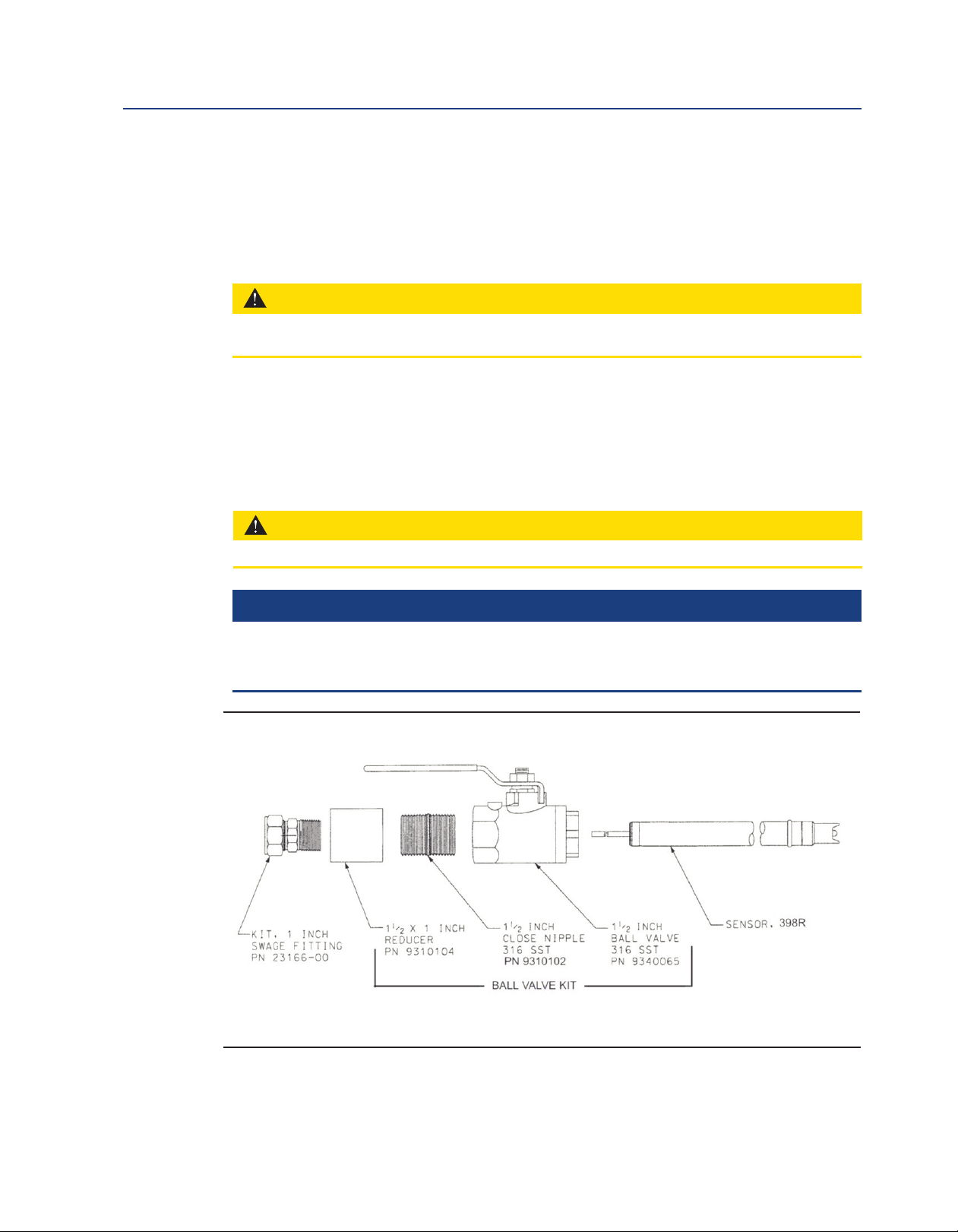
Figure 2-1: Exploded View of Ball Valve Kit PN 23240-00 used with process connector PN
23166-00 (or PN 23166-01)
Ball Valve Kit includes 1-1/2 in. x 1 in. reducer, 1-1/2 in. close nipple, and 1-1/2 in. ball valve]
Installation 9
Page 16
Installation Reference Manual
February 2019 00809-0100-3098
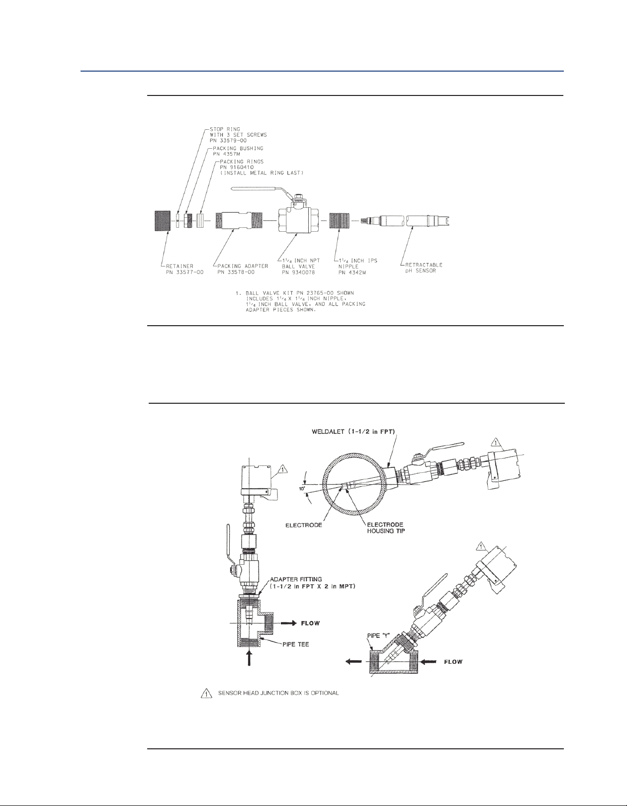
Figure 2-2: Exploded View of Ball Valve Kit PN 23765-00
2.3.2 Installation Without Ball Valve
Rosemount 398R and 398RVP Sensors may be installed through a weldalet or pipe tee or “Y” when
used with a process connector (PN 23166-00 or 23166-01). The sensor should be installed within
80° of vertical, with the electrode facing down.
Figure 2-3: Typical Mounting Details-Retraction Version
Note: Sensor must be mounted at an angle between 10° and 90° above the horizontal.
Pipe tees and weldalets provided by customer.
Only Rosemount 398R should be used with a sensor head junction box.
10 Calibration and Maintenance
Page 17
Reference Manual Installation
00809-0100-3098 February 2019
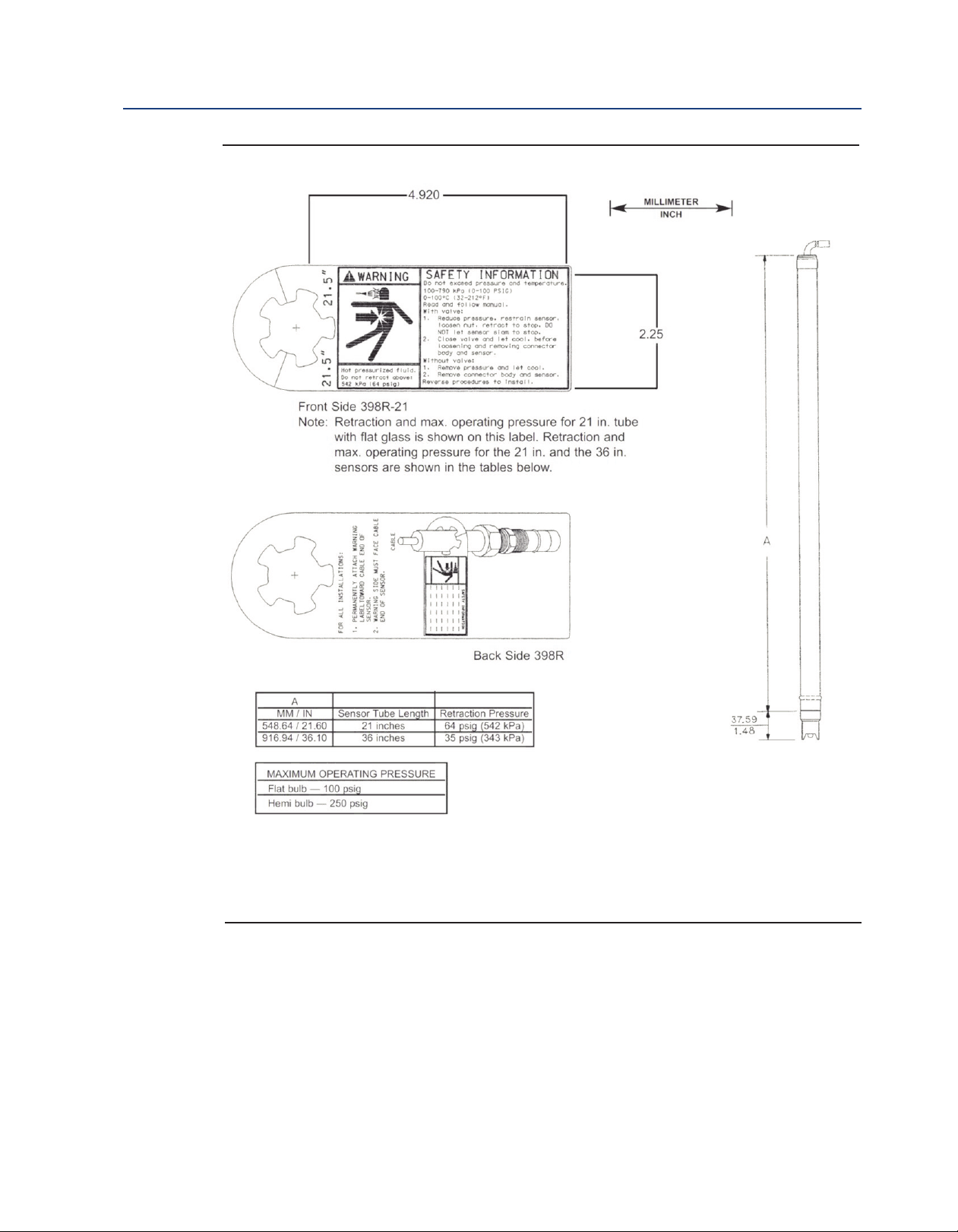
Figure 2-4: Dimensional Warning Label and Sensor Diagram
Note: For Rosemount 398RVP, the overall dimensional length increases by 1.9 inches (48 mm).
Calibration and Maintenance 11
Page 18

Installation Reference Manual
February 2019 00809-0100-3098
Figure 2-5: Dimensional Drawing for Ball Valve Kit PN 23765-00
(shown with Rosemount 398RVP sensor)
12 Installation
Page 19

Reference Manual Installation
00809-0100-3098 February 2019
igure 2-6: Dimensional Drawing for Ball Valve Kit PN 23240-00
F
(shown with Rosemount 398R).
Note: For Rosemount 398RVP, the overall dimensional length increases by 1.9 inches (48 mm).
Installation 13
Page 20

Installation Reference Manual
February 2019 00809-0100-3098
Figure 2-7: Dimensional Drawing of Rosemount 398R shown with Sensor Head Junction Box,
ith and without 1-1/2 in. Ball Valve PN 23240-00
w
Note: For the installations shown, the 1 in. x 1 in. process connector (PN 23166-00 or 23166-01), sensor
head junction boxes (various part numbers; see page 3), and ball valve kit (PN 23240-00) must be
purchased separately.
Note: Sensor head junction boxes should be used with Rosemount 398R sensor
14 Installation
Page 21

Reference Manual Wiring the Rosemount 398R/398RVP Sensor
00809-0100-3098 February 2019
Section 3: Wiring the Rosemount
398R/398RVP Sensor
3.1 Wiring for Rosemount 398R/398RVP
For wiring diagrams not shown below, please refer to the Liquid Wiring Diagrams.
Figure 3-1: Wire Configurations
Figure 3-2: Wiring for Rosemount 398R-54-62 to 3081, 4081, and 5081 Transmitters.
Wiring the Rosemount 398R/398RVP Sensor
15
Page 22

Wiring the Rosemount 398R/398RVP Sensor Reference Manual
February 2019 00809-0100-3098
Figure 3-3: Wiring for 398R-54-62 Through Remote Junction Box PN 23555-00
Note: Sensor Model 398R-54 or 398R-54-60 can also be wired as shown above, but customer must
prepare the BNC as shown in Figure 3-4. For preparing wires on end of extension cable, use Figure 3-5.
16 Wiring the Rosemount 398R/398RVP Sensor
Page 23

Reference Manual Wiring the Rosemount 398R/398RVP Sensor
00809-0100-3098 February 2019
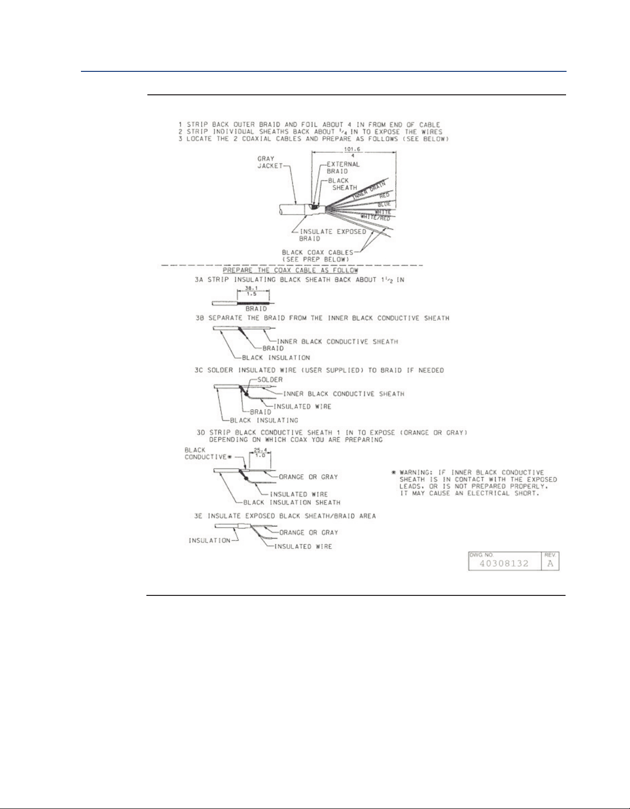
Figure 3-4: BNC Preparation Instructions
Wiring the Rosemount 398R/398RVP Sensor 17
Page 24
Wiring the Rosemount 398R/398RVP Sensor Reference Manual
February 2019 00809-0100-3098
Figure 3-5: Extension Cable Preparation
18 Wiring the Rosemount 398R/398RVP Sensor
Page 25
Reference Manual Wiring the Rosemount 398R/398RVP Sensor
00809-0100-3098 February 2019
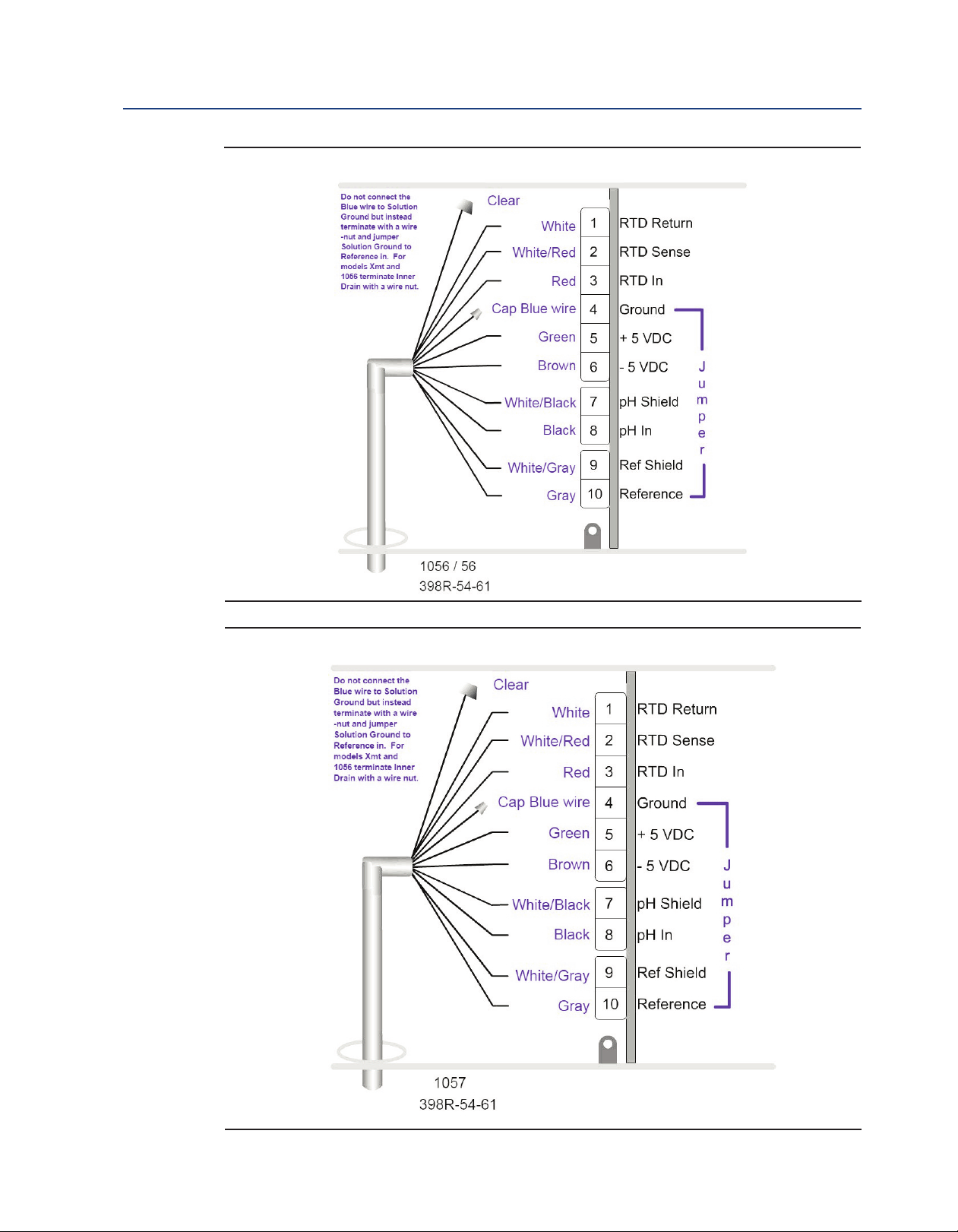
Figure 3-6: Rosemount 398R-54-61 Wiring to Rosemount 1056/56 Transmitters
Figure 3-7: Rosemount 398R-54-61 Wiring to Rosemount 1057 Transmitter
Wiring the Rosemount 398R/398RVP Sensor 19
Page 26

Wiring the Rosemount 398R/398RVP Sensor Reference Manual
February 2019 00809-0100-3098
Figure 3-8: Rosemount 398R-54-61 Wiring to Rosemount 1066 Transmitter
Figure 3-9: Rosemount 398R-54-61 Wiring to Rosemount 5081
20 Wiring the Rosemount 398R/398RVP Sensor
Page 27

Reference Manual Wiring the Rosemount 398R/398RVP Sensor
00809-0100-3098 February 2019
Figure 3-10: Rosemount 398R-xx-xx-54-62 Wiring to Rosemount 1056/56/1057 Transmitters
Figure 3-11: Rosemount 398R-xx-xx-54-62 Wiring to Rosemount 1066 Transmitter
Wiring the Rosemount 398R/398RVP Sensor 21
Page 28
Wiring the Rosemount 398R/398RVP Sensor Reference Manual
February 2019 00809-0100-3098
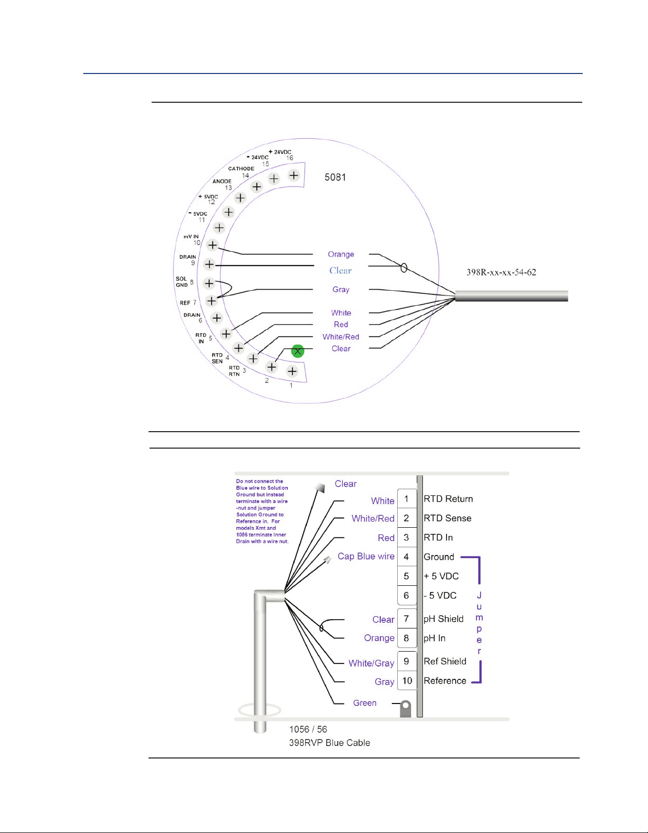
igure 3-12: Rosemount 398R-xx-xx-54-62 Wiring to Rosemount 5081 Transmitter
F
Figure 3-13: Rosemount 398RVP Wiring to Rosemount 1056/56 Transmitters
22 Wiring the Rosemount 398R/398RVP Sensor
Page 29

Reference Manual Wiring the Rosemount 398R/398RVP Sensor
00809-0100-3098 February 2019
igure 3-14: Rosemount 398RVP Wiring to Rosemount 1057 Transmitter
F
Figure 3-15: Rosemount 398RVP Wiring to Rosemount 1066 Transmitter
Wiring the Rosemount 398R/398RVP Sensor 23
Page 30

Wiring the Rosemount 398R/398RVP Sensor Reference Manual
February 2019 00809-0100-3098
Figure 3-16: Rosemount 398RVP Wiring to Rosemount 5081 Transmitter
Figure 3-17: Rosemount 398RVP-70 Wiring to Rosemount 1056/56/1057 Transmitters
24 Wiring the Rosemount 398R/398RVP Sensor
Page 31

Reference Manual Wiring the Rosemount 398R/398RVP Sensor
00809-0100-3098 February 2019
Figure 3-18: Rosemount 398RVP-70 Wiring to Rosemount 1066 Transmitter
Figure 3-19: Rosemount 398RVP-70 Wiring to Rosemount 5081 Transmitter
Wiring the Rosemount 398R/398RVP Sensor 25
Page 32

Wiring the Rosemount 398R/398RVP Sensor Reference Manual
February 2019 00809-0100-3098
26 Wiring the Rosemount 398R/398RVP Sensor
Page 33

Reference Manual Calibration
00809-0100-3098 February 2019
Section 5: Calibration
5.1 General Information
1. New sensors must be calibrated before use.
2. Regular recalibration is also necessary and is determined by the user.
3. The use of a two-point buffer calibration is always recommended.
4. Refer to the transmitter Reference Manual for more specific calibration procedures.
5.2 Use of Calibration Buffers (Standards)
1. Good buffers lead to good calibrations: A pH measurement is only as good as the
calibration, and the calibration is only as good as the buffers used. A careful buffer
calibration is the first step in making an accurate pH measurement.
2. Use appropriate buffers: Calibrate with buffers having pH values that bracket the pH of
the process. For example, if the pH is between 8 and 9, calibrate with pH 7 and 10 buffers.
Commercial buffers for intermediate range pH are readily available.
3. Sensor and buffers must be at the same temperature: Allow time for the sensor and buffers
to reach the same temperature. If the sensor was just removed from a process having a
temperature more than 10°C different from the buffer, allow at least 20 minutes.
4. Buffers must be at process temperature: For best results, calibrate with buffers having the
same temperature as the process. If the buffer and process temperature differ by more
than about 15°C an error as great as 0.1pH may result.
5. Be careful using buffers at very high temperatures: Protect the solution from evaporation.
Evaporation changes the concentration of the buffer and its pH. Be sure the pH of the
buffer is defined at high temperatures. The pH of many buffers is undefined above 60°C.
Finally, no matter what the temperature is, allow the entire measurement cell, sensor and
solution, to reach constant temperature before calibrating.
6. The pH of a buffer changes with temperature: The pH of a buffer is a function of
temperature. The pH of alkaline buffers depends more strongly on temperature than
the pH of acidic or neutral buffers. Most process pH instruments, including those
manufactured by Rosemount, have an auto calibration feature. The instrument
recognizes the buffer being used and automatically corrects for the change in buffer pH
with temperature. If the instrument does not perform the correction, the user must
enter the appropriate value. Buffer manufacturers usually list the temperature
dependence of the buffer on the label.
7. Buffers have limited shelf lives: Do not use a buffer if the expiration date has passed. Store
buffers at controlled room temperature.
8. Do not reuse buffers: Do not return used buffer to the stock bottle. Discard it.
9. Protect buffers from excessive exposure to air: Atmospheric carbon dioxide lowers the pH
of alkaline buffers. Other trace gases commonly found in industrial environments, for
example, ammonia and hydrogen chloride, also affect the pH of buffers. Molds, from
airborne spores, grow readily in neutral and slightly acidic buffers. Mold growth can
substantially alter the pH of a buffer.
Calibration 27
Page 34

Calibration Reference Manual
February 2019 00809-0100-3098
5.3 Two Point Buffer Calibration
1. Remove the protective vinyl cap from the sensor tip.
. Rinse the sensor and immerse it in the first buffer. Ensure that the glass bulb and the
2
temperature element are completely submerged by keeping the sensor tip about 3 inches
below the liquid level. Swirl the sensor to dislodge trapped air bubbles. Do not allow the
weight of the sensor to rest on the glass bulb.
3. Once the reading is stable, enter the buffer value in the analyzer. If the analyzer does not
correct for changes in buffer pH with temperature, be sure to enter the temperaturecorrected value.
4. Remove the sensor from the first buffer. Rinse the sensor and place it in the second buffer.
Follow the same precautions given in step 2.
5. Once the reading is stable, enter the buffer value in the analyzer. If the analyzer does not
correct for changes in buffer pH with temperature, be sure to enter the temperaturecorrected value.
6. After calibration, note the sensor slope. Slope has units of mV per unit change in pH. An
ideal sensor has a slope of 59 mV/pH at 25°C. Slope decreases as the sensor ages. Once
the slope drops to between 47 and 49 mV/pH, the sensor should be replaced.
7. Remove the sensor from buffer 2 and return it to the process liquid.
5.4 pH Standardization
Standardization means making the process instrument match the reading from a second pH meter.
The second pH reading is usually made on a grab sample.
1. Take the sample from a point as close as possible to the process sensor. To avoid starving
the process sensor, use a downstream sample point.
2. Wait until the process pH is constant or, at worst, slowly drifting before taking the grab
sample.
3. To ensure that measured pH is truly the pH of the process liquid, determine the pH of the
grab sample immediately. pH is a function of temperature. If the temperature of the
process differs from ambient, measure the pH of the grab sample before its temperature
changes. Some process liquids are poorly buffered. The pH of the sample may change
significantly upon exposure to air or to the sample container. To avoid deterioration of the
sample, measure the pH immediately.
4. Following the instructions in the instrument manual, adjust the process reading to the
value measured on the grab sample.
28 Calibration
Page 35

Reference Manual Calibration
00809-0100-3098 February 2019
5.5 ORP Standardization
There are relatively few ORP calibration standards available. The most popular one is a solution
containing 0.1 M iron (II) and 0.1 M iron (III) in 1 M sulfuric acid. The standard is available from
Rosemount as PN R508- 16OZ. The poten-tial of the solution measured against a silver-silver
hloride reference electrode is 475 ±20 mV at 25 °C.
c
1. Rinse the sensor with deionized water and place it in the ORP standard along with a reliable
thermometer. Submerge the sensor tip at least three inches below the surface of the liquid.
Swirl the sensor to dislodge trapped bubbles. Adjust the temperature of the standard
to 25 ±5 °C.
2. Wait until temperature and ORP readings are stable.
3. Following the instructions in the instrument analyzer, store ORP value (475 mV) in
memory.
4. Remove the sensor from the ORP standard, rinse it, and return it to the process fluid.
Calibration 29
Page 36

Calibration Reference Manual
February 2019 00809-0100-3098
30 Calibration
Page 37

Reference Manual Maintenance
00809-0100-3098 February 2019
Section 6: Maintenance
6.1 Maintenance
The frequency at which a sensor should be inspected, cleaned, and calibrated can be determined
only by experience. Generally, the greater the tendency of the process liquid to coat or foul the
sensor, the more frequently maintenance should be done. Rosemount 398R and 398RVP sensors
are fouling resistant and, they usually require maintenance less often than other pH (or ORP)
sensors. Sensors exposed to extreme pH values or to high temperature require more frequent
inspection than sensors installed in less severe environments. The best way to evaluate a sensor is
to check its performance in buffers. If the sensor cannot be calibrated or has low slope, it is dirty or
has failed. Refer to the troubleshooting guide in this manual for assistance.
6.2 Sensor Removal
Please refer to the appropriate paragraph for instructions regarding removal of the sensor for
periodic maintenance.
6.2.1 Retractable Version
WARNING
System pressure may cause the sensor to blow out with great force unless care is taken during removal.
Make sure the following steps are adhered to.
A. Rosemount 398R-21 and 398RVP-21 (21” tube)
1. Be certain system pressure at the sensor is below 64 psig before proceeding
with the retraction. It is also recommended that the personnel wear a face
shield and have a stable footing. Refer to Figure 6-1. Push in on the cable end or
the top of the junction box and slowly loosen the hex nut (B) of the process end
male connector (A).
Figure 6-1: Example of Sensor Tube Replacement
Maintenance 31
Page 38

Maintenance Reference Manual
February 2019 00809-0100-3098
B. Rosemount 398R-25 and 398RVP-25 (36” tube)
. Be certain that pressure at the sensor is below 35 psig before proceeding with the
2
retraction. It is also recommended that the personnel wear a face shield and have
a stable footing. Refer to Figure 6-1. Push in on the cable end or the top of the
junction box and slowly loosen the hex nut (B) of the process end male
connector (A).
CAUTION
Do not remove nut at this time.
3. When the hex nut is loose enough, slowly ease the sensor back completely until
the retraction stop collar (mechanical safety stop) is reached.
CAUTION
Failure to withdraw the sensor completely may result in damage to the sensor when the valve is closed.
4. Close the ball valve slowly. If there is resistance, the valve may be hitting the
sensor. Double check that the sensor has been retracted to the retraction stop collar.
WARNING
Before removing the sensor from the ball valve, be absolutely certain that the ball valve is fully closed.
Leakage from the male connector threads may indicate that the male connector is still under pressure.
Leakage through a partially open valve could be hazardous, however with the ball valve closed, some
residual process fluid may leak from the connector's pipe threads.
5. The Male Connector Body (A) may now be completely unthreaded from the
reducing coupling and the sensor removed for servicing.
CAUTION
If the male connector leaks during insertion or retraction, replace the O-ring (PN 9550167) in the male
connector A.
6.3 Cleaning Procedures - pH Sensors
To remove the sensor from the process piping, follow the instructions in Section 6.2.
CAUTION
Only persons thoroughly familiar with the procedure for diluting concentrated hydrochloric acid should
prepare the solution. Dilute the acid in a fume hood or in a well-ventilated area. Point the acid bottle away
from people when opening it. Wear appropriate safety equipment, including chemical goggles and gloves.
Do not let acid touch the skin or clothing. If acid solutions contact the skin or eyes, rinse thoroughly with
water. Seek medical assistance.
32 Maintenance
Page 39
Reference Manual Maintenance
00809-0100-3098 February 2019
Problem Cleaning Suggestions
Loose scale or debris Use a stream of water from a wash bottle to rinse away solids from the tip of the
ensor. If water does not work, gently wipe the glass bulb and liquid junction with
s
a soft cloth, tissue, cotton-tipped swab, or a soft bristle brush.
Oil and grease Wash the glass bulb with mild detergent solution and rinse thoroughly with water.
Hard scale (carbonate and sulfate scales and
orrosion products)
c
When using acid or alkaline solvents, be careful to keep the solvent away from the liquid junction.
See Figure 6-2. If the cleaning solvent contacts the junction, hydrogen ions (acid solvent) or
hydroxide ions (alkaline solvent) will diffuse into the junction. Because hydrogen and hydroxide
ions have much greater mobility than other ions, they produce a large junction potential.
When the electrode goes back in service, the hydrogen or hydroxide ions slowly diffuse out of the
junction, causing the liquid junction potential and the pH reading to drift. It may take hours or days
for the reading to stabilize.
Always recalibrate the sensor after cleaning. If the sensor was cleaned with detergent or acid, soak
the sensor in pH 4 or pH 7 buffer for at least an hour before calibrating.
Figure 6-2: Tip of Rosemount 398R pH Sensor
If wiping the sensor tip with a tissue or cotton swab does not remove the scale,
oak the the glass bulb ONLY in a solution of 5% hydrochloric acid. To prepare the
s
acid solution, add 15 mL of concentrated hydrochloric acid to 85 mL of water with
continuous stirring. See CAUTION below. Keep the acid away from the liquid junction. Rinse the sensor thoroughly with deionized water. Some scales (for example,
calcium sulfate) cannot be removed easily with acid. Soaking the glass bulb in a 2%
solution of disodium EDTA for 20 minutes may be helpful.
The figure shows the tip of the Rosemount 398R pH sensor. The bottom of the liquid junction is
about even with the top of the wings that form the slotted tip. Keep acidic and alkaline solvents
away from the liquid junction. If acids or bases get into the junction, subsequent pH readings may
drift for several hours.
Maintenance 33
Page 40

Maintenance Reference Manual
February 2019 00809-0100-3098
6.4 Cleaning Procedures - ORP Sensors
Clean platinum ORP electrodes by using a tissue to rub the metal surface with a paste of baking
oda (sodium bicarbonate). A clean platinum electrode is bright and shiny.
s
6.5 Checking the Reference Electrode
Some processes contain substances, for example, sulfides, that poison the reference electrode.
Poisoning alters the electrode potential. For example, sulfide poisoning converts the reference
electrode from a silver/silver chloride electrode into a silver/silver sulfide electrode, causing a
shift in potential of several hundred millivolts.
A good way to check for poisoning is to compare the voltage of the reference electrode with a
silver/silver chloride electrode that is known to be good. The reference electrode from a new
sensor is the best choice. To check the suspect electrode, place both sensors in a beaker
containing buffer or a solution of potassium chloride. Connect the reference leads to a volt
meter and measure the potential difference. If the suspect electrode is good, the difference
should be no more than about 20 mV.
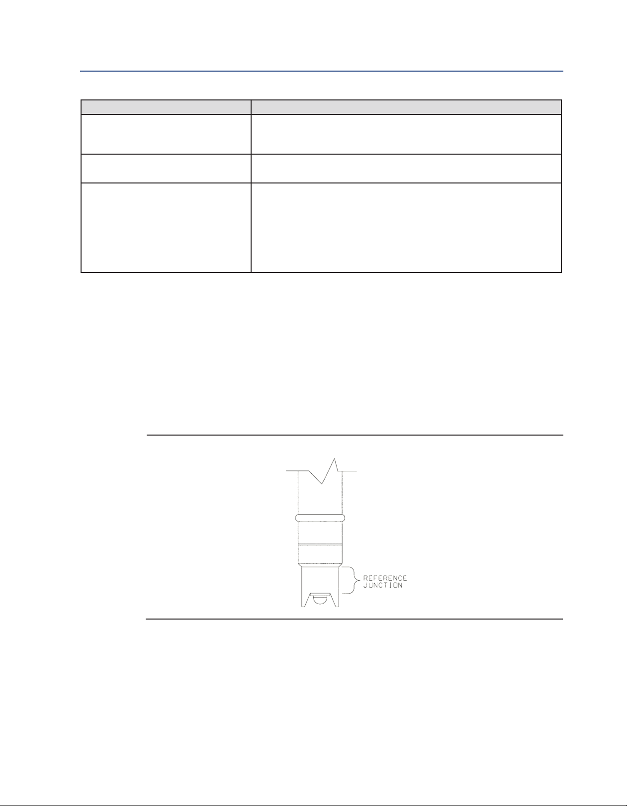
Refer to Figure 6-3. A poisoned reference electrode usually requires replacement. A laboratory
silver/silver chloride reference electrode can be used in place of the second sensor. All Rosemount
pH sensors have a silver/silver chloride reference, and most sensors use gelled saturated
potassium chloride for the fill. The potentials of a good sensor reference electrode and a saturated
silver/ silver chloride laboratory electrode will agree within about 20 mV.
Figure 6-3: Checking the Potential of the Reference Electrode
34 Maintenance
Page 41
Reference Manual Maintenance
00809-0100-3098 February 2019
6.6 Rejuvenating Reference Electrodes
ccasionally, a poisoned or plugged reference electrode can be reconditioned. Although the
O
electrode seldom recovers completely, the procedure might extend the life of the sensor by a few
weeks.
a. Clean the sensor as thoroughly as possible.
b. Soak the sensor for several hours in a hot (NOT BOILING) 3% potassium chloride solution.
Prepare the solution by dissolving 3 g of potassium chloride in 100 mL of water.
c. Soak the sensor in pH 4 buffer at room temperature overnight.
d. Calibrate the sensor in buffers and retest it in the process liquid.
Table 6-1: Resistance as a Function of Temperature for Selected RTDs.
Temperature °C Resistance (Ohms) ±1
3K PT-100
0 2670 100.0
10 2802 103.8
20 2934 107.7
25 3000 109.6
30 3066 111.5
40 3198 115.4
50 3330 119.2
60 3462 123.1
70 3594 126.9
80 3726 130.8
90 3858 134.6
100 3990 138.5
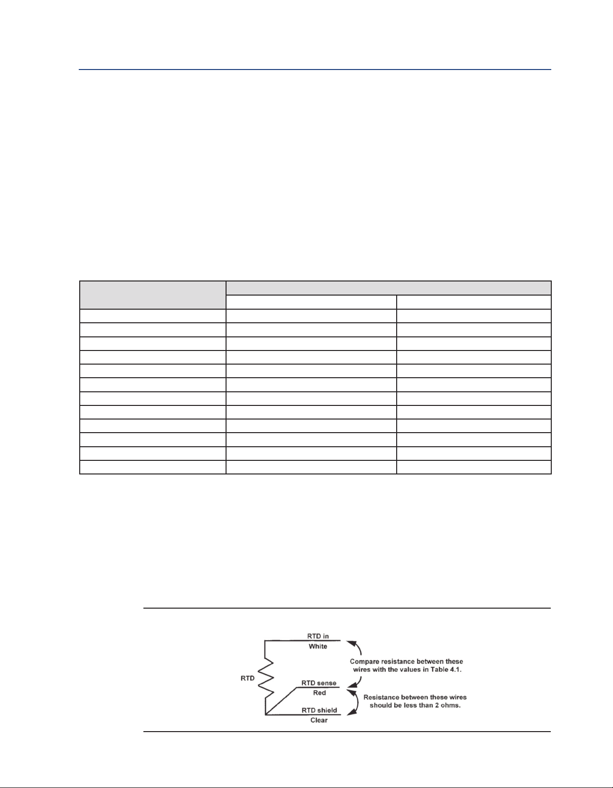
6.7 Temperature Element
Rosemount 398R/398RVP pH sensors produce a voltage which the instrument converts to pH using
a temperature-dependent factor. A Pt 100 or a Balco 3K RTD built into the sensor measures
temperature. To permit cor-rection for changes in lead resistance with temperature, a three-wire
configuration (Figure 6-4) is used. To check the RTD, disconnect the leads and measure the
resistances shown. The measured resistance should agree with the value in the table to within
about ±1%. If the measured resistance is appreciably dif-ferent (between 1 and 5%), the discrepancy can
be calibrated out. See the instrument Reference Manual.
Figure 6-4: Three-wire RTD circuit
Maintenance 35
Page 42

Maintenance Reference Manual
February 2019 00809-0100-3098
Consult Table 6.1 (above) for temperature-resistance data. Lead resistance is about 0.05 ohm/ft at
25°C. Therefore, 15 ft of cable increases the resistance by about 1.5 ohm. The resistance between
he RTD return and RTD sense leads should be less than 2 ohms. If a connection is open or shorted
t
and should not be, replace the sensor. If the measured resistance is greatly in error, replace the
sensor.
6.8 Sensor Tube Replacement When Used With A
Sensor Head Junction Box
Replace ment of the retraction versions sensor tube assembly involves the removal and installation
of two sets of male connectors: One at the process end of the sensor, and the other at the junction
box end (See Figure 6-1 and Figure 6-5). Refer to Section 6.2 for proper removal of the sensor from
process.
1. Remove sensor from process before proceeding. The junction box with attached male
connector must be recovered from the old sensor for reuse. Unscrew the junction box
cover and set aside. Disconnect electrical connections from printed circuit board inside
junction box. Disconnect BNC connector to preamp. Unscrew hex nut (F) from male
connector body (E). Separate junction box from used sensor. Set aside.
2. Pry off split ferrule from sensor and set aside for reuse. Remove hex nut (F) and set aside
for reuse. Check that the internal O-ring is in place in the male connector body (E)
attached to .the junction box.
3. Remove hex nut (B) from male connector body (A) at process end of sensor and set aside.
Slide the Teflon ferrule and the male connector off sensor in the direction of junction box
and set.
Note: If stainless steel ferrule was used, male connector body (A) will have to be dis carded with
the sensor tube.
4. Discard used O-ring from male connector body (A). Coat new O-ring with a thin film of the
O-ring lubricant provided. Position it in the machined O-ring groove in place of the
discarded O-ring.
CAUTION
Make sure lubricant does not contact any part of the sensor tip particularly the glass bulb.
5. Cover the 1" MNPT pipe threads of the male connector body (A) with Teflon tape (not
provided) to protect them from galling during reinstallation.
6. Pass the wires from the new sensor through the process end male connector (A). Make
sure that the beveled edge of the ferrule faces the process end of the sensor. Snug the hex
nut (B) to keep it in place. Do not tighten down fully on the hex nut at this time.
7. Pass the wires from the new sensor through the hex nut (F), the split ferrule (from the old
sensor), male connector body (E), O-ring, and through the junction box from the “neck”
opening and out to the printed circuit board in the junction box. Butt the ferrule’s beveled
edge and the sensor tube against the junction male connector (E).
8. Screw the hex nut (F) by hand until the tube is “locked” into the male connector body.
36 Maintenance
Page 43

Reference Manual Maintenance
00809-0100-3098 February 2019
9. Make sure that the male connector body (E) is sufficiently tightened.
10. The sensor will “click” into place by pulling the sensor tube away from the junction box,
but will not move from side to side or pull clear of the male connector.
11. If the sensor tube is correctly attached to the junction box, wrench tighten hex nut (F) on
male connector body (E). See Figure 6-1.
12. Do not put the sensor tube in a vise or use a pipe wrench to tighten the hardware as these
will damage the sensor. If sensor tube is not correctly attached to the junction box, loosen
hex nut (F) and repeat.
13. Connect the sensor wires to the terminals on the printed circuit board in the junction box
in the manner recommended on the junction box cover,and reattach the BNC connector
to the preamp.
14. Screw on the cover of the junction box aside. Discard sensor tube.
15. Insert the sensor in the process fitting. Stop it against the closed ball valve. Slide the
process-end male connector down the sensor tube to mate with the process fitting.
Tighten the male connector into the process fitting.
16. Pull back hard on the sensor assembly, as if trying to remove the sensor, to be certain that
the sensor cannot come free from the valve assembly and male connector. The built-in
retraction stop collar at the end of the sensor will butt against the shoulder of the male
connector.
17. Open ball valve and position the sensor at the desired insertion depth and orientation.
Using a crescent or open end wrench, tighten the hex nut (B) to secure the sensor in place.
See Figure 6-5.
Note: A stainless steel ferrule is available if the Teflon ferrule does not adequately grip. Be careful
and avoid over tightening. This can damage the sensor tube.
Figure 6-5: Male Connector Tightening Diagram
CAUTION
If the male connector leaks during insertion or retraction, replace the O-ring (PN 9550167) in the male
connector A.
If the sensor is to be stored, the rubber boot should be filled with 7pH buffer solution and replaced
on sensor tip until ready to use.
Maintenance 37
Page 44

Maintenance Reference Manual
February 2019 00809-0100-3098
38 Maintenance
Page 45
Reference Manual Troubleshooting
00809-0100-3098 February 2019
Section 7: Troubleshooting
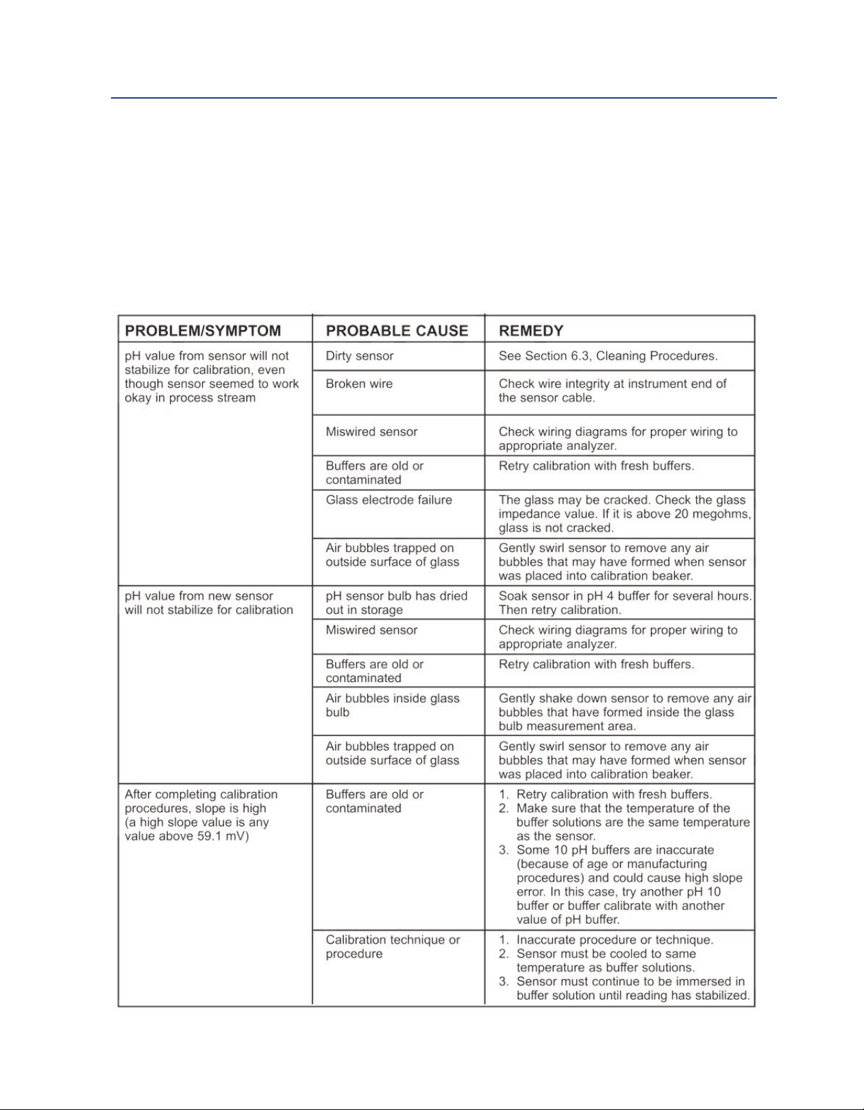
7.1 Troubleshooting
Table 7-1, below, lists common problems, causes and remedies typically encountered in process
measurement. For more specific troubleshooting information, please refer to the appropriate
transmitter manual.
able 7-1: Troubleshooting
T
Note: For any repair or warranty inquiries please contact our Customer Care group.
Troubleshooting 39
Page 46

Troubleshooting Reference Manual
February 2019 00809-0100-3098
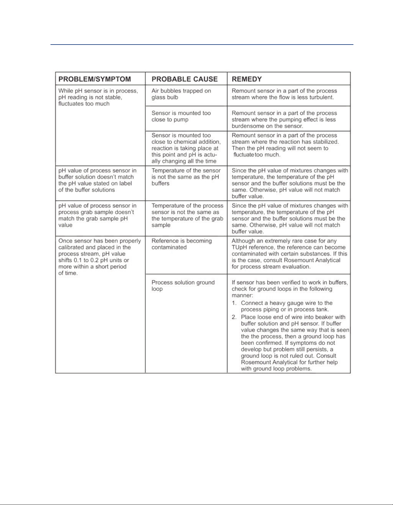
Table 7-1: Troubleshooting (continued)
40 Troubleshooting
Page 47
Reference Manual Troubleshooting
00809-0100-3098 February 2019
Table 7-1: Troubleshooting (continued)
Troubleshooting 41
Page 48

42 Heading title
Page 49

Reference Manual Accessories
00809-0100-3098 February 2019
Section 8: Accessories
8.1 Accessories
Table 8-1: Accessories for Rosemount 398R/398RVP
Part Number Description
23557-00 Preamplifier for remote junction box (PN 23555-00),
23550-00 Remote Junction box with extension board
9550099 O-ring, Viton, for process connector
9550220 O-ring, Kalrez, for process connector
9210012 Buffer solution, 4.01 pH, 16 oz
9210013 Buffer solution, 6.86 pH, 16 oz
9210014 Buffer solution, 9.18 pH, 16 oz
Accessories 43
Page 50

Accessories Reference Manual
February 2019 00809-0100-3098
44 Accessories
Page 51

(signature)
Vice President of Global Quality
(function)
Chris LaPoint
(name)
1-Feb-19; Shakopee, MN USA
(date of issue & place)
EU Declaration of Conformity
No: RAD 1119 Rev. B
pH/ORP Sensors
We,
Rosemount Inc.
8200 Market Boulevard
Chanhassen, MN 55317-9685
USA
declare under our sole responsibility that the product,
Rosemount™ Sensor Models:
328A, 385, 385+ -04, 385+ -02/03, 385+-03-12, 389-01, 389-01-10/11-50, 389-01-10/11-54,
389-01-12-50, 389-01-12-54, 389-01-12-55, 389-02, 389VP, 389VP-70, 396, 396P-01-10/13-50,
396P-01-10/13-54, 396P-01-12-50, 396P-01-12-54, 396P-01-12-55, 396P-01-55, 396VP,
396VP-70, 396R, 396RVP, 396RVP-70, 396P-02, 396PVP, 396PVP-70, 397, 398, 398VP,
398R, 398RVP, 398RVP-70, 3200HP, 3300HT, 3300HT VP, 3300HTVP-70, 3400HT, 3400HT
VP, 3400HTVP-70, 3500P-01, 3500P-01-12, 3500P-02, 3500VP-01, 3500VP-01-12, 3500VP-02,
3800, 3800VP, 3900-01, 3900-02, 3900VP-01, 3900VP-02
manufactured by,
Rosemount Inc.
8200 Market Boulevard
Chanhassen, MN 55317-9685
USA
to which this declaration relates, is in conformity with the provisions of the European Union Directives,
including the latest amendments, as shown in the attached schedule.
Assumption of conformity is based on the application of the harmonized standards and, when applicable
or required, a European Union notified body certification, as shown in the attached schedule.
Page 1 of 3
Page 52

EU Declaration of Conformity
No: RAD 1119 Rev. B
ATEX Directive (2014/34/EU)
Baseefa10ATEX0156X– Intrinsically Safe
Equipment Group II, Category 1 G Ex ia IIC T4 Ga (-20°C ≤ Ta ≤ +60°C)
(exceptions noted below)
Model 328A Steam sterilizable pH sensor with integral cable
Model 385 Retractable pH/ORP sensor with integral cable
Model 385+ -04 pH/ORP sensor with integral cable
Model 385+ -02/03 pH/ORP sensor with integral cable & Smart preamplifier
Model 385+ -03-12 ORP sensor with integral cable & preamplifier: T4 (-20°C ≤ Ta ≤ +80°C), T5
(-20°C ≤ Ta ≤ +40°C)
Model 389-01 pH sensor with integral cable & Smart preamplifier
Model 389-01-10/11-50 pH sensor with integral cable & preamplifier: T4 (-20°C ≤ Ta ≤ +80°C)
or T5 (-20°C ≤ Ta ≤ +40°C)
Model 389-01-10/11-54 pH sensor with integral cable & preamplifier: T4 (-20°C ≤ Ta ≤ +80°C)
or T5 (-20°C ≤ Ta ≤ +40°C)
Model 389-01-12-50 ORP sensor with integral cable & preamplifier: T4 (-20°C ≤ Ta ≤ +80°C)
Model 389-01-12-54 ORP sensor with integral cable & preamplifier: T4 (-20°C ≤ Ta ≤ +80°C)
Model 389-01-12-55 ORP sensor with integral cable & preamplifier: T4 (-20°C ≤ Ta ≤ +80°C)
Model 389-02 pH/ORP sensor with integral cable
Model 389VP-70 pH sensor with Variopole connector & Smart preamplifier
Model 389VP pH/ORP sensor with Variopole connector
Model 396 TUpH sensor with integral cable
Model 396P-01-10/13-50 polypropylene pH sensor with integral cable & preamp: T4 (-20°C ≤ Ta
≤ 80°C) or T5 (-20°C ≤ Ta ≤ 40°C)
Model 396P-01-10/13-54 polypropylene pH sensor with integral cable & preamp: T4 (-20°C ≤ Ta
≤ 80°C) or T5 (-20°C ≤ Ta ≤ 40°C)
Model 396P-01-12-50 ORP sensor with integral cable & preamp: T4 (-20°C ≤ Ta ≤ +80°C)
Model 396P-01-12-54 ORP sensor with integral cable & preamp: T4 (-20°C ≤ Ta ≤ +80°C)
Model 396P-01-12-55 ORP sensor with integral cable & preamp: T4 (-20°C ≤ Ta ≤ +80°C)
Model 396P-01-55 pH sensor with integral cable & Smart preamp
Model 396VP TUpH sensor with Variopole connector
Model 396VP-70 TUpH sensor with Variopole connector & Smart preamplifier
Model 396R TUpH Retractable pH/ORP sensor with integral cable
Model 396RVP TUpH Retractable pH/ORP sensor with Variopole connector
Model 396RVP-70 TUpH Retractable pH sensor with Variopole connector & Smart preamplifier
Model 396P-02 TUpH Polypropylene pH/ORP sensor with integral cable
Model 396PVP TUpH Polypropylene pH/ORP sensor with Variopole connector
Model 396PVP-70 TUpH Polypropylene pH sensor with Variopole connector & Smart
preamplifier
Model 397 TUpH sensor with integral cable
Model 398 TUpH pH/ORP sensor with integral cable
Model 398VP TUpH pH/ORP sensor with Variopole connector
Model 398R TUpH Retractable pH/ORP sensor with integral cable
Model 398RVP TUpH Retractable pH/ORP sensor with Variopole connector
Model 398RVP-70 TUpH Retractable pH sensor with Variopole connector & Smart preamplifier
Model 3200HP Flowing junction pH sensor with Variopole connector
Model 3300HT Insertion/submersion pH sensor with integral cable
Model 3300HTVP Insertion/submersion pH sensor with Variopole connector
Page 2 of 3
Page 53

EU Declaration of Conformity
No: RAD 1119 Rev. B
Model 3300HTVP-70 Insertion/submersion pH sensor with Variopole connector & Smart
preamplifier
Model 3400HT Retractable pH sensor with integral cable
Model 3400HTVP Retractable pH sensor with Variopole connector
Model 3400HTVP-70 Retractable pH sensor with Variopole connector & Smart preamplifier
Model 3500P-01 High performance pH sensor with integral cable & Smart preamplifier
Model 3500P-01-12 PerpH-X ORP sensor with integral cable & preamplifier: T4 (-20°C ≤ Ta ≤
+80°C)
Model 3500P-02 High performance pH sensor with integral cable
Model 3500VP-01 High performance pH sensor with Variopole connector & Smart preamplifier
Model 3500VP-01-12 PerpH-X ORP sensor with Variopole connector & preamplifier: T4 (-20°C
≤ Ta ≤ +80°C)
Model 3500VP-02 High performance pH sensor with Variopole connector
Model 3800 Steam sterilizable pH sensor with single pole Eurocap connector
CE marking was first affixed to this product in 2011
Model 3800VP Steam sterilizable pH sensor with Variopole connector
Model 3900-01 pH/ORP sensor with integral cable & Smart preamplifier
Model 3900-02 pH/ORP sensor with integral cable
Model 3900VP-01 pH sensor with Variopole connector & Smart preamplifier
Model 3900VP-02 pH/ORP sensor with Variopole connector
Special conditions for safe use:
1) All pH/ORP sensor models with a plastic enclosure or exposed plastic parts may
provide an electrostatic ignition
hazard and must only be cleaned with a damp cloth to avoid the danger of ignition due to
a buildup of electrostatic
charge.
2) All pH/ORP sensor models with a metallic enclosure may provide a risk of ignition by
impact or friction. Care should be
taken during installation to protect the sensor from this risk.
3) External connections to the sensor must be suitably terminated and provide a degree of
protection of at least IP20.
All pH/ORP sensor models are intended to be in contact with the process fluid and may
not meet the 500V r.m.s test to earth. This must
be taken into consideration at installation.
Harmonized Standards:
EN 60079-0:2012+A11:2013
EN 60079-11:2012
ATEX Notified Body for EC Type Examination Certificate & Quality Assurance
SGS FIMKO OY [Notified Body Number: 0598]
P.O. Box 30 (Särkiniementie 3)
00211 HELSINKI
Finland
Page 3 of 3
Page 54

China RoHS Table Reference Manual
February 2019 00809-0100-3098
48 China RoHS Table
Page 55
ANY FM APPROVED
ASSOCIATED APPARATUS
HAVING ENTITY PARAMETERS
NO
N-
H
AZARDOUS
(UNCLASSIFIED)
AREA
CLASS I, II, III, DIVISION 1, GROUPS A-G
T6 Ta = 60C
SENSOR
ENTITY PARAMETERS
Ui = 13.1U, Ii = 358m A
Pi = 698 m W
Ci = 0.967 F, Li = 0.1m H
1. NO REVISION TO THIS DRAW ING IS PERMITTED W ITHO UT
FM APPROVAL.
2. U
m ax
> U
t
; I
m ax
> I
t
; (C
i
OF ALL LOO PS + C CABLE) < C
a
;
(L
i
OF ALL LOOPS + L CABLE) < L
a
, P
m ax
OR P
i
> P
0.
3. SINGLE M ULTI-CHANNEL
IS BARRIER OR APPARATUS M UST BEFM APPROVED,
4. SINGLE M ULTI-CHANNEL
IS BARRIER OR APPARATUS M ANUFACTURE’S
CONTROL DRAW INGS M UST BE FOLLOW ED W HEN INSTALLING THE SYSTEM .
IS BARRIER OR EQUIPM ENT M AY BE INSTALLED W ITHIN THE HAZARDOUS
(CLASSIFIED) LOCATION FOR W HICH IT IS APPROVED
.
5. INSTALLATIO N M UST BE IN ACCORDANCE W ITH ARTICL
E 500 OF THE NEC
(ANSI/NFPA 70) AND ANSI/ISA RP 12.6.
W ARNING: SUBSTITUTION OF COM PONENTS MAY IM PA
IR INTRINSIC SAFETY.
6. pH & AM PEROM ETRIC SENSORS W ITHOUT PREAM PS ARE SIM PLE APPARATUS.
ZON E
ZONE 0
7. CONTROL EQUIPM ENT CONNECTED TO THE ASSOCIATED APPARATUS M UST
NO T USE OR GENERATE M ORE THAN 250V.
RESISTANCE BETW EEN INTRINSICALLY SAFE GROUND AND EARTH GROUND
M UST BE LESS THAN OR EQUAL TO 1 OHM.
ANY
FM APPROVED TRANSMITTER FOR
DIVISION 1 W ITH INTRINSICALLY SAFE
OUTPUT PARAMETERS. THIS
FM
APPROVED DEVICE M UST BE INSTALLED
PER ITS INSTALLATION DRAW ING.
FM
APPROVED EQUIPMENT (M AY BE
M ULTIPLE DEVICES, NUMBER IS LIMITED
BY REQ UIREM ENTS TO M EET ALL OTHER
IS REQUIREMENTS FO R THE NETW ORK)
W ITH EQUIVALENT HAZARDOUS AREA
APPROVALS.
H
AZARDOUS
(CLASSI
F
IED)
AREA
INTRISICALLY SA FE
9. pH/O RP SENSOR M ODELS THAT M AY CONTAIN THE PREAM PLIFIER:
3900/VP
3500/VP
3300HT/VP
3400HT/VP
396/VP
396R/VP
396P/VP
398R/VP
399/VP
389/VP
385/385+
10. W ARNING: TO PREVENT IGNITION OF FLAM M ABLE OR COM BUSTIBLE
ATMOSPHERES, DISCONNECT POW ER BEFORE SERVIC
ING.
11. THE ENTITY CONCEPT ALLOW S INTECONNECTION OF INTRINSICALLY SAFE
APPARATUS W ITH ASSOCIATED APPARATUS W HEN THE FOLLO W ING IS TRUE:
U
i
> U
o;
I
i
> I
o;
P
i
> P
o;
C
o
> C
i
+ C CABLE; L
o
> L
i
+ L CABLE.
12. COPY REVISIONS TO 1400332 TO pH/O RP SHIPPING M ANUALS.
13 Ci INCLUDES THE CAPACITANCE OF 500 FEET OF SENSOR CABLE.
13
DW G NO.
1400332
8.
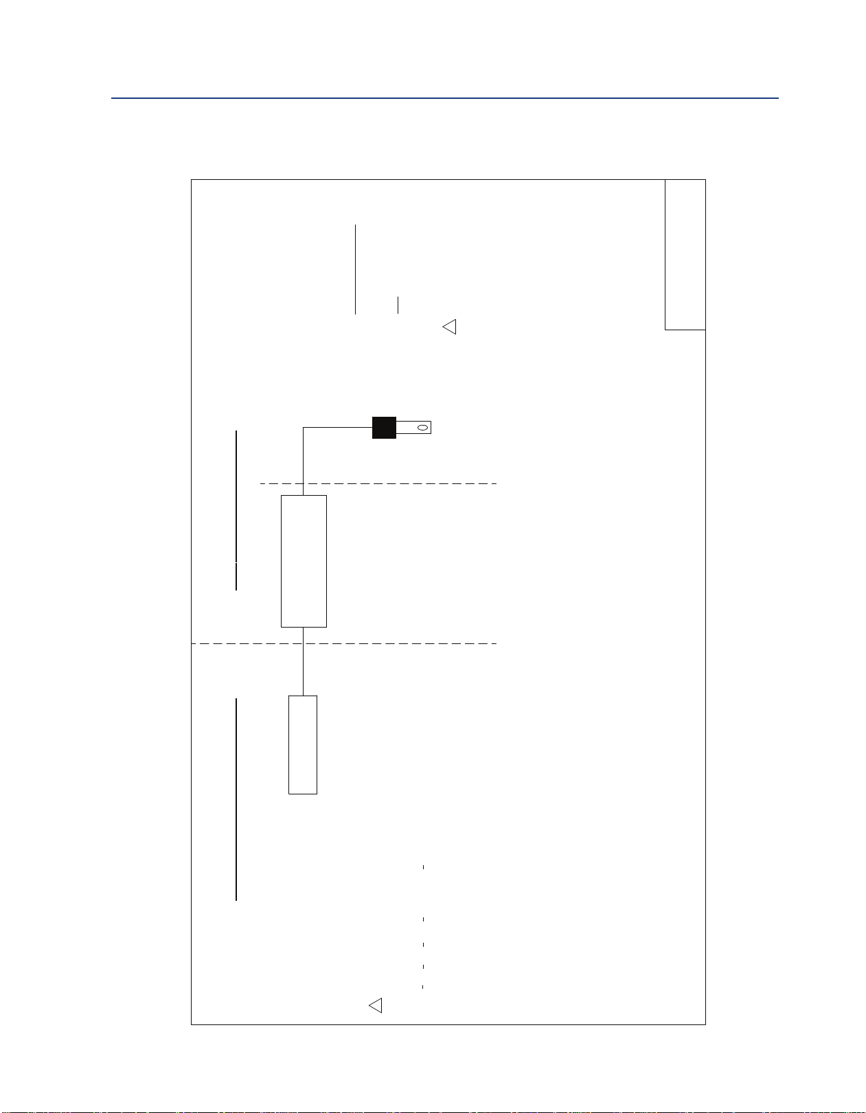
Reference Manual FM Installation
00809-0100-3098 February 2019
Intrisically Safe Sensor Installation Drawing - FM
FM Installation 49
Page 56

00809-0100-3098
Rev. AB
February 2019
www.Emerson.com/RosemountLiquidAnalysis
Youtube.com/user/Rosemount
Twitter.com/Rosemount_News
Emerson
8200 Market Blvd.
Chanhassen, MN 55317,
USA
Tel +1 800 999 9307
Fax +1 952 949 7001
Liquid.CSC@Emerson.com
©2019 Emerson. All rights reserved.
The Emerson logo is a trademark and service mark of Emerson Electric Co. Rosemount is a mark of
one of the Emerson family of companies. All other marks are the property of their respective
owners.
The contents of this publication are presented for information purposes only, and while effort has
been made to ensure their accuracy, they are not to be construed as warranties or guarantees,
express or implied, regarding the products or services described herein or their use or applicability.
All sales are governed by our terms and conditions, which are available on request. We reserve the
right to modify or improve the designs or specifications of our products at any time without notice.
fa
cebo
o
k
.co
m/
Ro
s
emo
unt
 Loading...