

Page 1
Rosemount™ 396P/396PVP
pH/ORP Sensors
Quick Start Guide
00825-0100-3096, Rev AA
November 2020
Page 2

Quick Start Guide November 2020
Essential instructions
Read this page before proceeding!
Emerson designs, manufactures, and tests its products to meet many national and international
standards. Because these instruments are sophisticated technical products, you must properly install,
use, and maintain them to ensure they continue to operate within their normal specifications. You
must adhere to the following instructions and integrate them into your safety program when
installing, using, and maintaining Emerson's Rosemount™ products. Failure to follow the proper
instructions may cause any one of the following situations to occur: loss of life, personal injury,
property damage, damage to this instrument, and warranty invalidation.
• Read all instructions prior to installing, operating, and servicing the product.
• If you do not understand any of the instructions, contact your Emerson representative for
clarification.
• Follow all warnings, cautions, and instructions marked on and supplied with the product.
• Inform and educate your personnel in the proper installation, operation, and maintenance of the
product.
• Install equipment as specified in the Installation section of this Quick Start Guide. Follow
appropriate local and national codes. Only connect the product to electrical and pressure sources
specified in this Quick Start Guide.
• To ensure proper performance, use qualified personnel to install, operate, update, program, and
maintain the product.
• When replacement parts are required, ensure that qualified people use replacement parts
specified by Emerson. Unauthorized parts and procedures can affect the product's performance,
place the safe operation of your process at risk, and may result in fire, electrical hazards, or
improper operation.
• Ensure that all equipment doors are closed and protective covers are in place, except when
maintenance is being performed by qualified people, to prevent electrical shock and personal
injury.
Note
The information contained in this document is subject to change without notice.
WARNING
Hazardous area installation
Installations near flammable liquids or in hazardous area locations must be carefully evaluated by
qualified on site safety personnel.
To secure and maintain intrinsically safe installation, use an appropriate transmitter/safety barrier/
sensor combination. The installation system must be in accordance with the governing approval
agency (FM, CSA, or BASEEFA/CENELEC) hazardous area classification requirements. Consult your
transmitter Reference Manual for details.
Proper installation, operation, and servicing of this sensor in a hazardous area installation are
entirely the operator's responsibility.
2 Emerson.com/Rosemount
Page 3
November 2020 Quick Start Guide
WARNING
Physical access
Unauthorized personnel may potentially cause significant damage to and/or misconfiguration of end
users’ equipment. This could be intentional or unintentional and needs to be protected against.
Physical security is an important part of any security program and fundamental to protecting your
system. Restrict physical access by unauthorized personnel to protect end users’ assets. This is true for
all systems used within the facility.
CAUTION
Sensor/process application compatibility
The wetted sensor materials may not be compatible with process composition and operating
conditions.
Application compatibility is entirely the operator's responsibility.
CAUTION
Sensor/process application compatibility
All pH/ORP sensors have a plastic enclosure which must only be cleaned with a damp cloth to
avoid the danger due to a build up of electrostatic charge.
All pH/ORP sensor models are intended to be in contact with the process fluid and may not meet
the 500 r.m.s.a.c. test to earth.
Take this into consideration at the time of installation.
Contents
Install........................................................................................................................................... 5
Wire........................................................................................................................................... 17
Start up and calibrate................................................................................................................. 37
Maintenance.............................................................................................................................. 40
Diagnostics and troubleshooting................................................................................................44
Return of material...................................................................................................................... 50
Rosemount pH/ORP sensor(s) product certifications..................................................................51
Declaration of Conformity..........................................................................................................58
China RoHS table........................................................................................................................60
Intrinsically safe sensor installation drawing - FM........................................................................61
Quick Start Guide 3
Page 4

Quick Start Guide November 2020
4 Emerson.com/Rosemount
Page 5
November 2020 Quick Start Guide
1 Install
1.1 Unpack and inspect
Procedure
1. Inspect the outside of the carton for any damage. If you detect
damage, contact the carrier immediately.
2. Inspect the hardware. Make sure all the items in the packing list are
present and in good condition. Notify the factory if any part is
missing.
Note
Save the original packing cartons and materials as most carriers
require proof of damage due to mishandling, etc. Also, if it is
necessary to return the sensor to the factory, you must pack the
sensor in the same manner as it was received. Refer to Return of
material for return instructions.
WARNING
Buffer solution in the vinyl boot may cause skin or eye irritation.
Wear personal protective equipment.
Avoid contact with skin and eyes.
CAUTION
Glass electrode must be wetted at all times (in storage and in line) to
maximize sensor life.
Postrequisites
If the sensor appears to be in satisfactory condition, proceed to Mount
sensor.
1.2
Quick Start Guide 5
Mount sensor
Emerson has designed the sensor to be located in industrial process
environments.
Do not exceed temperature and pressure limitations at any time. A caution
label regarding this matter is attached to the sensor. Please do not remove
the label.
See Figure 1-1 for dimensional information to ensure proper installation into
your process.
Page 6
Quick Start Guide November 2020
WARNING
Pressurized spray injury
US and foreign patents pending.
Do not exceed pressure and temperature specifications: 0 to 150 psig (0
to 1135 kPa), 32 to 212 °F (0 to 100 °C).
Remove pressure and allow to cool before removal.
Read and follow Quick Start Guide.
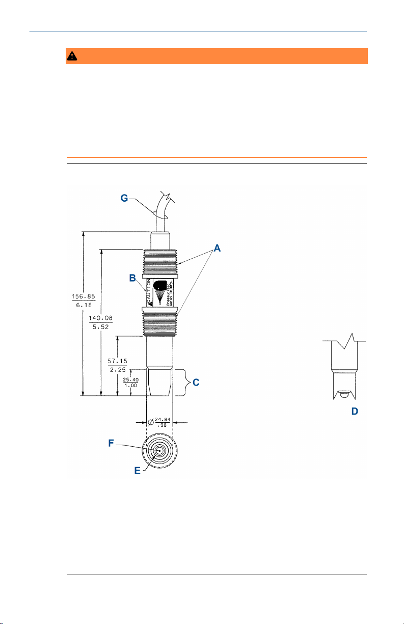
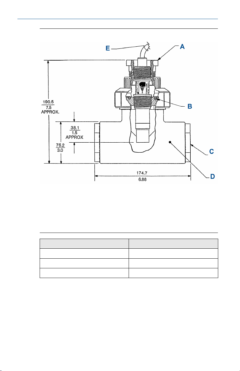
Figure 1-1: Dimensional Drawing
A. 1-in. (25.4 mm) male national pipe thread (MNPT), two places
B. 1-in. (25.4 mm) wrench opening
C. Reference junction
D. End tip option -41
E. Solution ground
F. Electrode
G. Sensor cable (or Variopol connector - not shown)
6 Emerson.com/Rosemount
Page 7

November 2020 Quick Start Guide
WARNING
Internal electrolyte fill solution may cause skin or eye irritation.
Wear personal protection equipment (PPE).
Avoid contact with skin and eyes.
1. Shake the sensor in a downward motion to remove any air bubbles
that may be present inside the tip of the pH glass.
2. Do not install the sensor on the horizontal. The sensor must be 10
degrees off the horizontal to ensure accuracy.
3. Do not install the sensor upside down.
4. Air bubbles may become trapped in the sensor end between the
glass bulb and the sensor body. This problem is most commonly
encountered in areas of low flow or during calibration. Shake the
probe while immersed in solution to remove bubbles. To avoid this
problem, order the sensor with the slotted tip (option -41).
In most cases, you can simply install the pH sensor as shipped and obtain
readings with an accuracy of ±0.6 pH. To obtain greater accuracy or to verify
proper operation, calibrate the sensor as a loop with its compatible
transmitter.
1.2.1 Flow through and insertion mounting
Rosemount 396P and 396PVP Sensors have a 1-in. (25.4 mm) male national
pipe thread (MNPT) process connection at the front of the sensor for
mounting into a 1½-in. (38.1 mm) tee or the process pipes.
See Figure 1-2 through Figure 1-8 for installation configurations.
Note
Do not use large pipe wrenches to tighten the sensor into a flange or other
type of mounting.
Quick Start Guide 7
Page 8
Quick Start Guide November 2020
Figure 1-2: Flow-Through Tee with Adapter (PN 915240-xx)
Pressure/temperature: 60 psig at 120 °F (514 kPa at 49 °C)
A. Adapter retrofit PN 33211-00
B. O-ring must be in place prior to use
C. Process connection threads - two places
D. 2-in. (50.8 mm) sched. 80 T
E. Sensor cable
Ordering option (xx)
03 ¾ in. (19.1 mm)
04 1 in. (25.4 mm)
05 1½ in. (38.1 mm)
8 Emerson.com/Rosemount
Process connection threads
Page 9
November 2020 Quick Start Guide
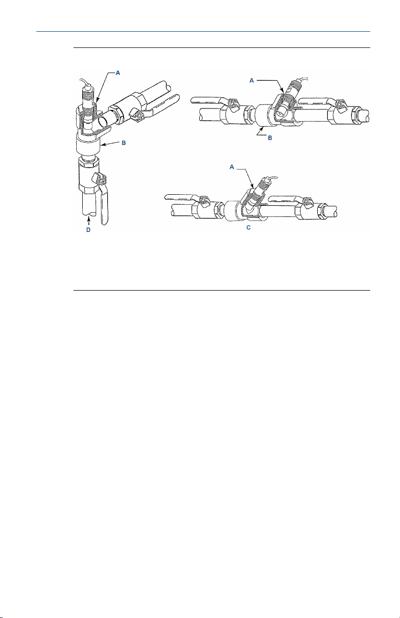
Figure 1-3: Flow-Through and Insertion Installations
A. 1½-in. x 1-in. (38.1 mm x 25.4 mm) reducing bushing
B. 1½-in. (38.1 mm) pipe tee PN 2002011
C. 1½-in. (38.1 mm) pipe Y
D. Flow
Quick Start Guide 9
Page 10
Quick Start Guide November 2020
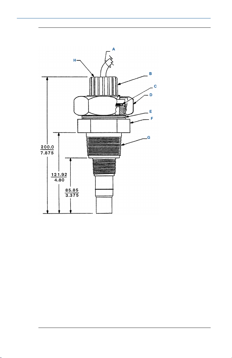
Figure 1-4: Rosemount 396P with Insertion Mounting Adapter (PN
23242-02)
Not for use with Rosemount 396PVP. Mounting adapter allows for sensor
removal without twisting or disconnecting interconnecting cable for ease of
maintenance.
A. Cable or Variopol connector (not shown)
B. Peek adapter 1-in. (25.4 mm) female national pipe thread (FNPT) x ¾-in.
(19.1 mm) FNPT
C. 2-135 Viton™ O-ring. O-ring must be in place prior to use (PN 9550175).
D. Nut, hex union 2-in. (50.8 mm); 3-in. (76.2 mm) wrench opening (304
stainless steel)
E. 3.531.8 acme thread (typ)
F. Neck, union fitting (316 stainless steel) 2⅝-in. (66.7 mm) wrench
opening
G. 1½-in. (38.1 mm) male national pipe thread (MNPT). Insertion mounting
adapter PN 23242-02 (includes polyetheretherketone [PEEK] adapter,
304 stainless steel union fitting)
H. ¾-in. (19.1 mm) FNPT
10 Emerson.com/Rosemount
Page 11
November 2020 Quick Start Guide
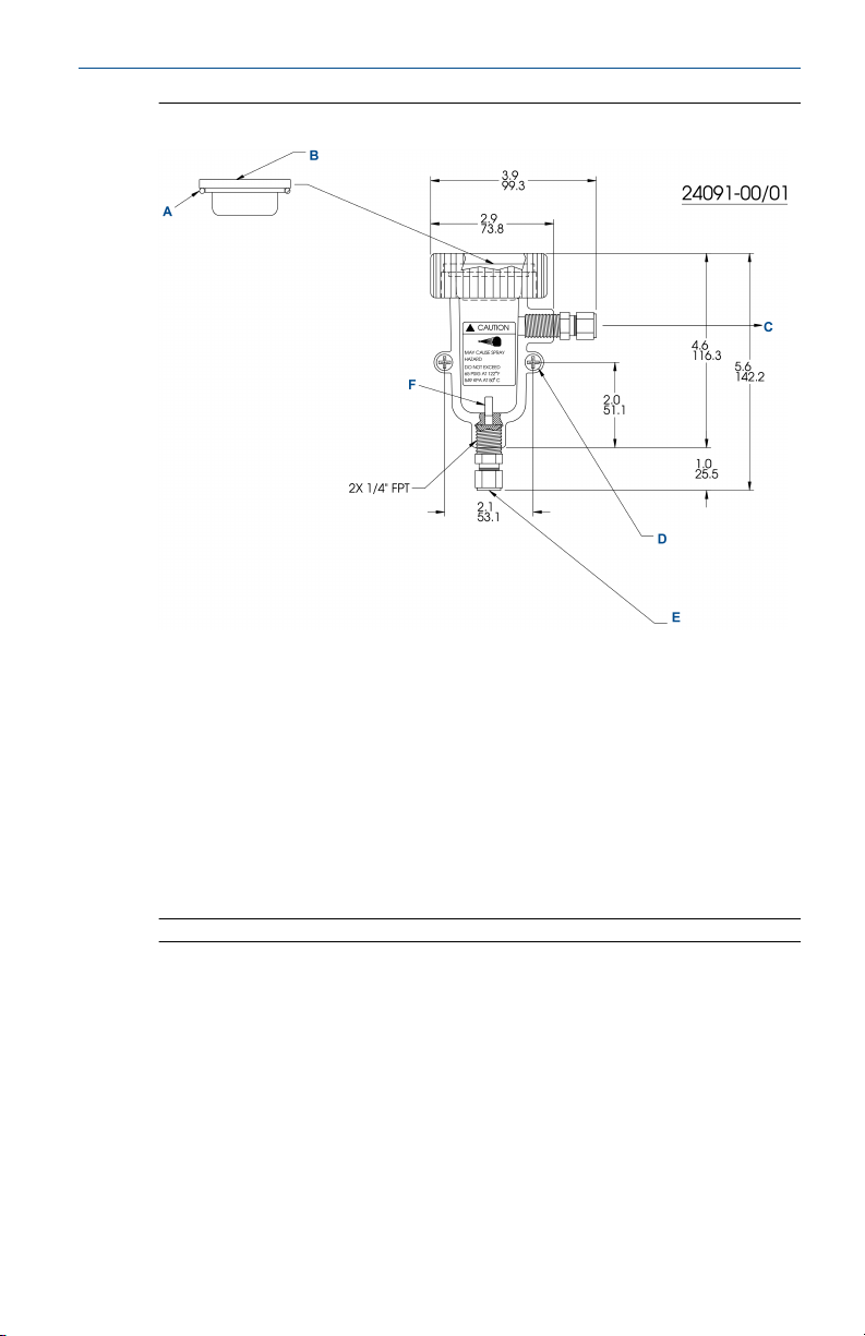
Figure 1-5: Low Flow Cell (PN 24091-00)
A. O-ring PN 9550298
B. Adapter with one national pipe thread (NPT) thread
C. ¼-in. (6.4 mm) O.D. tubing outlet
D. Supplied hardware:
10-32 x 2.5-in. (63.5 mm) stainless steel (two)
10-32 hex nut, stainless steel (two)
#10 flat washer, stainless steel (two)
10-32 cap nut, nylon (two)
E. ¼-in. (6.4 mm) O.D. tubing inlet
F. Nozzle PN 33822-00, -01 only
Note
1. Materials of construction:
Flow cell, adapter, and nut: polycarbonate/polyester
Nozzle: Noryl
™
O-ring: Silicone
¼-in. (6.4 mm) male connectors: stainless steel
Mounting hardware: stainless steel
2. Pressure/temperature rating: Maximum: 65 psig at 122 °F (549 kPa at
50 °C)
Quick Start Guide 11
Page 12

Quick Start Guide November 2020
3. This flow cell assembly is used for pressurized applications. See 2 for
limitations.
Unless otherwise specified.
12 Emerson.com/Rosemount
Page 13
November 2020 Quick Start Guide
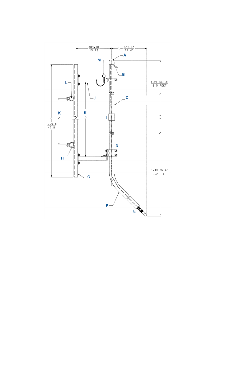
Figure 1-6: Handrail Mounting Assembly (PN 11275-01)
A. End cap PVC
B. Sensor cable
C. 1½-in. (38.1 mm) PVC pipe schedule 80
D. 1½-in. (38.1 mm) pipe clamp, three places
E. Sensor model Rosemount 396P. Regularly check to make sure
connections are water tight.
F. Sweep pipe with 1-in. (25.4 mm) FNPT adapter
G. Unistrut 1⅝ x 1⅝-in. (41.3 x 41.3 mm) aluminum
H. 1½-in. (38. mm) pipe clamp, two places
I. Coupling
J. Mounting channel aluminum, two places
K. Can be any convenient dimension
L. Customer handrail, two places
M. Locking pin with bead chain
Quick Start Guide 13
Page 14
Quick Start Guide November 2020
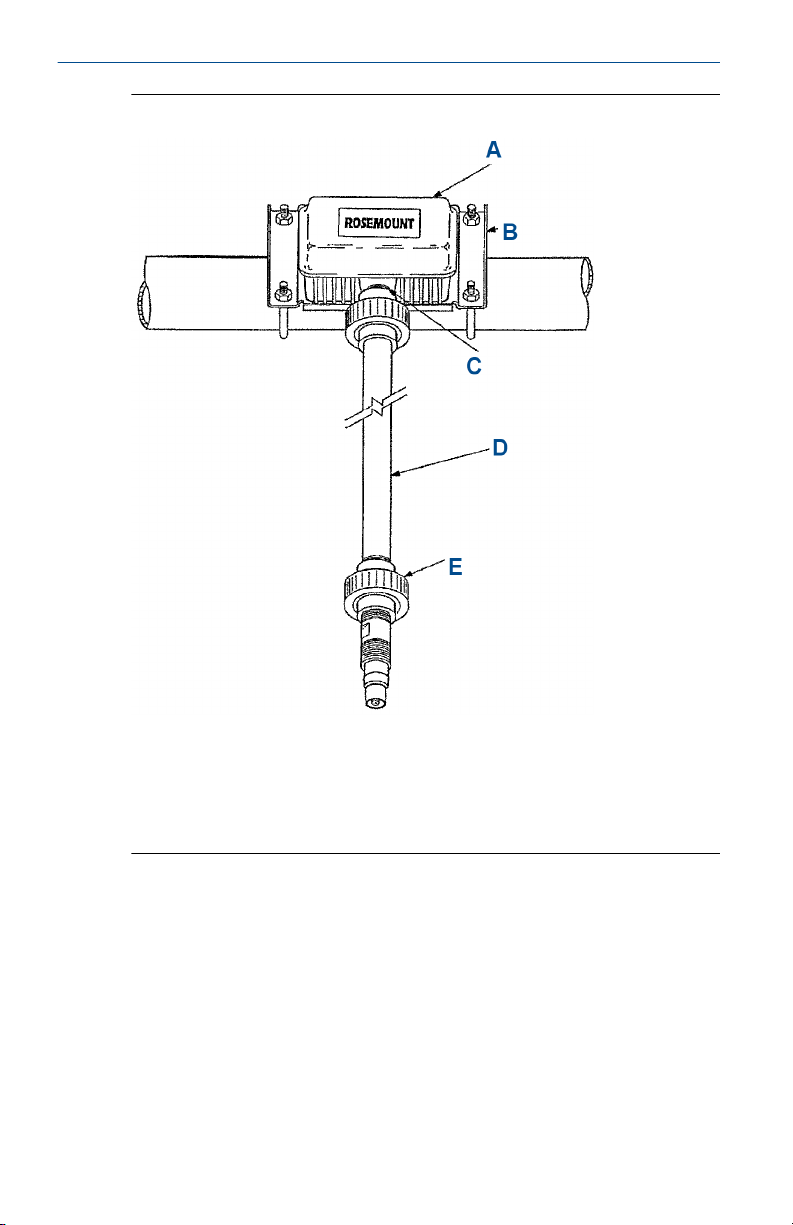
Figure 1-7: Junction Box
A. Junction box
B. 2-in. (50.8 mm) pipe mounting bracket (PN 2002565)
C. Flexible conduit if required
D. 1-in. (25.4 mm) pipe by others
E. 1-in. (25.4 mm) FNPT CPVC union (PN 9320057)
14 Emerson.com/Rosemount
Page 15
November 2020 Quick Start Guide
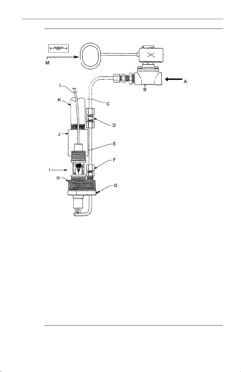
Figure 1-8: Jet Spray Cleaner (PN 12707-00)
A. Cleaning solution by others
B. Solenoid valve or manual valve (supplied by others)
C. Corrosion resistant tubing (supplied by others)
D. Polypropylene ¼-in. (6.4 mm) compression fitting
E. ¼-in. (6.4 mm) 316 stainless steel
F. ¼-in. (6.4 mm) polypropylene
G. Stainless set screw for adjustable spray nozzle height
H. 2-in. (50.8 mm) NPT threads
I. Sensor
J. 1-in. (25.4 mm) PVC couping for submersible applications (supplied by
others)
K. 1-in. (25.4 mm) PVC or stainless conduit (supplied by others)
L. Cable
M. Timer supplied by others or use timer feature in Rosemount instrument
Quick Start Guide 15
Page 16

Quick Start Guide November 2020
1.2.2 Submersion mounting
Rosemount 396P and 396PVP sensors also have a 1-in. (25.4 mm) male
national pipe thread (MNPT) process connection at the back of the sensor.
Using a standard 1-in. (25.4 mm) union, you can mount the sensor to a 1-in.
(25.4 mm) schedule 80 CPVC or PVDF standpipe.
Tapered pipe threads in plastic tend to loosen after installation. Therefore,
Emerson recommends using PTFE tape on the threads and checking the
tightness of the connection frequently to assure that no loosening has
occurred. To prevent rain water or condensation from running into the
sensor, Emerson recommends using a weatherproof junction box. Run the
sensor cable through a protective conduit for isolation from electrical
interference or physical abuse from the process. Install the sensor within 80
degrees of vertical, with the electrode facing down. Do not run the sensor's
cable with power or control wiring.
16 Emerson.com/Rosemount
Page 17

November 2020 Quick Start Guide
2 Wire
2.1 General wiring guidelines
Figures in Wiring diagrams provide guidelines for wiring the Rosemount
396P sensor to various transmitters.
To determine which wiring diagram to use, locate the model number of the
sensor to be installed.
If you need to extend the cable, use a high quality eleven conductor doubleshielded instrument cable (part number 9200273) available from Emerson.
Note
If the cable is too long, loop up the excess cable. If you need to shorten the
cable, cut and terminate each conductor neatly and make sure that the
overall (outermost) drain wire is not shorted out with either of the two inner
drain wires (shields).
Run signal cable in a dedicated conduit (preferably an earth grounded
metallic conduit) and keep it away from AC power lines. For your
convenience, Emerson has furnished a wire nut kit (in a plastic bag wrapped
around the cable).
CAUTION
For maximum electromagnetic interference/radio frequency interference
(EMI/RFI) protection when wiring from the sensor to the junction box,
connect the outer braid of the sensor to the outer braided shield of the
extension cable. Terminate the outer braid of the extension cable to the
instrument at earth ground or use an appropriate metal cable gland fitting
to provide a secure connection to the instrument cable.
2.2 Wiring diagrams
The Rosemount 396P has an optional built-in preamplifier and comes with a
shielded cable.
WARNING
Serious injury may result.
Do not connect sensor cable to power lines.
Quick Start Guide 17
Page 18

Quick Start Guide November 2020
CAUTION
Handle the cable carefully and keep it dry and free of corrosive chemicals
at all times.
Take extreme care to prevent it from being twisted, damaged, or
scraped by rough, sharp edges or surfaces.
Note
Remove electrical tape or shrink sleeve away from gray reference wire
before connecting wire to terminal.
Note
For additional information on this product, including sensor combinations
not shown here, please refer to our website Wiring Diagrams.
18 Emerson.com/Rosemount
Page 19
November 2020 Quick Start Guide
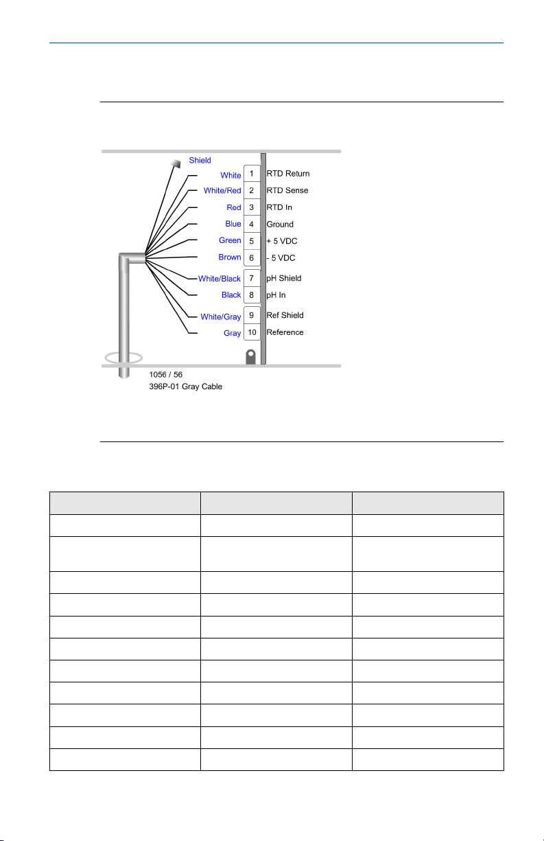
Figure 2-1 and Table 2-1 are applicable to option codes -01, -03, -04, and
-05.
Figure 2-1: Wiring for Rosemount 396P (Gray Cable) and Rosemount
1056, 56, or 1057
If there is a shrink sleeve on the gray reference wire, remove it before
connecting the wire to the terminal. For Rosemount 1056, terminate inner
drain with a wire nut.
Table 2-1: Wiring for Rosemount 396P (Gray Cable) and Rosemount 1056, 56, or
1057
Terminal number Wire color Connects to
N/A Shield N/A
1 White Resistance temperature
2 White/red RTD sense
3 Red RTD in
4 Blue Solution ground
5 Green +5 Vdc
6 Brown -5 Vdc
7 White/black pH shield
8 Black pH in
9 White/gray Reference shield
10 Gray Reference
Quick Start Guide 19
device (RTD) return
Page 20
Quick Start Guide November 2020
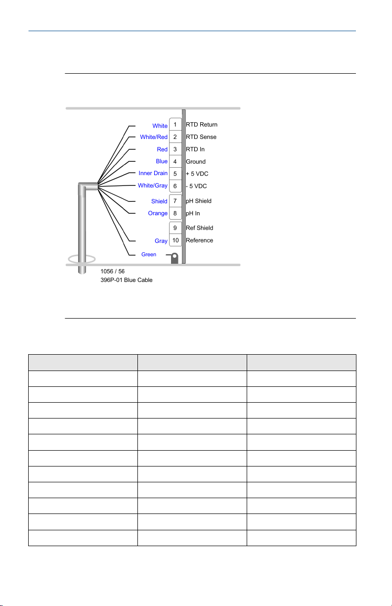
Figure 2-2 and Table 2-2 are applicable to option codes -01, -03, -04, and
-05.
Figure 2-2: Wiring for Rosemount 396P (Blue Cable) and Rosemount
1056, 56, or 1057
If there is a shrink sleeve on the gray reference wire, remove it before
connecting the wire to the terminal. For Rosemount 1056, terminate inner
drain with a wire nut.
Table 2-2: Wiring for Rosemount 396P (Blue Cable) and Rosemount 1056, 56, or
1057
Terminal number Wire color Connects to
1 White RTD return
2 White/red RTD sense
3 Red RTD in
4 Blue Solution ground
5 Inner drain +5 Vdc
6 White/gray -5 Vdc
7 Shield pH shield
8 Orange pH in
9 N/A Reference shield
10 Gray Reference
N/A Green N/A
20 Emerson.com/Rosemount
Page 21

November 2020 Quick Start Guide
Figure 2-3 and Table 2-3 are applicable to option codes -02, -07, and -0.8
Figure 2-3: Wiring for Rosemount 396P and Rosemount 1056, 56, or
1057
If there is a shrink sleeve on the gray reference wire, remove it before
connecting the wire to the terminal. For Rosemount 1056, terminate inner
drain with a wire nut.
Table 2-3: Wiring for Rosemount 396P and Rosemount 1056, 56, or 1057
Terminal number Wire color Connects to
N/A Shield N/A
1 White RTD return
2 White/red RTD sense
3 Red RTD in
4 Blue Solution ground
5 N/A +5 Vdc
6 N/A -5 Vdc
7 Braid pH shield
8 Orange pH in
9 Braid Reference shield
10 Gray Reference
Quick Start Guide 21
Page 22

Quick Start Guide November 2020
Figure 2-4 and Table 2-4 are applicable to option codes -02, -07, and -08.
Figure 2-4: Wiring for Rosemount 396P (Blue Cable) and Rosemount
1056, 56, or 1057
If there is a shrink sleeve on the gray reference wire, remove it before
connecting the wire to the terminal. For Rosemount 1056, terminate inner
drain with a wire nut.
Table 2-4: Wiring for Rosemount 396P (Blue Cable) and Rosemount 1056, 56, or
1057
Terminal number Wire color Connects to
N/A Shield N/A
1 White RTD return
2 White/red RTD sense
3 Red RTD in
4 Blue Solution ground
5 N/A +5 Vdc
6 N/A -5 Vdc
7 Braid pH shield
8 Orange pH in
9 White/gray Reference shield
10 Gray Reference
N/A Green Ground
22 Emerson.com/Rosemount
Page 23

November 2020 Quick Start Guide
Figure 2-5: Wiring for Rosemount 396PVP without Integral Preamplifier
and Rosemount 1056, 56, or 1057
If there is a shrink sleeve on the gray reference wire, remove it before
connecting the wire to the terminal. For Rosemount 1056, terminate inner
drain with a wire nut.
Table 2-5: Wiring for Rosemount 396PVP without Integral Preamplifier and
Rosemount 1056, 56, or 1057
Terminal number Wire color Connects to
N/A Clear N/A
1 White RTD return
2 White/red RTD sense
3 Red RTD in
4 Blue Solution ground
5 N/A +5 Vdc
6 N/A -5 Vdc
7 Clear pH shield
8 Orange pH in
9 Clear Reference shield
10 Gray Reference
Quick Start Guide 23
Page 24

Quick Start Guide November 2020
Figure 2-6: Wiring for Rosemount 396PVP-70 and Rosemount 1056, 56,
or 1057
Table 2-6: Wiring for Rosemount 396PVP-70 and Rosemount 1056, 56, or 1057
Terminal number Wire color Connects to
1 White RTD return
2 White/red Sense
3 Red RTD in
4 Blue Solution ground
5 Inner drain +5 Vdc
6 White/gray -5 Vdc
7 Clear pH shield
8 Orange pH in
9 N/A Reference shield
10 Gray Reference
N/A Green No connection or earth
ground
24 Emerson.com/Rosemount
Page 25

November 2020 Quick Start Guide
Figure 2-7 and Table 2-7 are applicable to option codes -01, -03, -04, -05,
and -06.
Figure 2-7: Wiring for Rosemount 396P (Gray Cable) and Rosemount
1066
Note
• If ground lead is present, terminate it to green ground screw on inner
enclosure.
• TB5, TB7, and TB8 not used for pH/ORP sensor wiring.
Table 2-7: Wiring for Rosemount 396P (Gray Cable) and Rosemount 1066
Terminal number Wire color Connects to
TB3 White RTD return
TB3 White/red RTD sense
TB3 Red RTD in
TB4 Green Preamplifier: +volts
TB4 Brown Preamplifier: -volts
TB1 Black/white pH shield
TB1 Black pH in
TB2 Blue Solution ground
TB2 White/gray Reference shield
TB2 Gray Reference in
Quick Start Guide 25
Page 26

Quick Start Guide November 2020
Figure 2-8 and Table 2-8 are applicable to option codes -01, -03, -04, -05,
and -06.
Figure 2-8: Wiring for Rosemount 396P (Blue Cable) and Rosemount
1066
Note
• If ground lead is present, terminate it to green ground screw on inner
enclosure.
• TB5, TB7, and TB8 not used for pH/ORP sensor wiring.
Table 2-8: Wiring for Rosemount 396P (Blue Cable) and Rosemount 1066
Terminal number Wire color Connects to
TB3 White RTD return
TB3 White/red RTD sense
TB3 Red RTD return in
TB4 Inner drain Preamplifier: +volts
TB4 White/gray Preamplifier: -volts
TB1 Shield pH shield
TB1 Orange pH in
TB2 Blue Solution ground
TB2 Gray Reference in
26 Emerson.com/Rosemount
Page 27

November 2020 Quick Start Guide
Figure 2-9 and Table 2-9 are applicable to option codes -02, -07, and -08.
Figure 2-9: Wiring for Rosemount 396P (Gray Cable) and Rosemount
1066
Note
• If ground lead is present, terminate it to green ground screw on inner
enclosure.
• TB5, TB7, and TB8 not used for pH/ORP sensor wiring.
Table 2-9: Wiring for Rosemount 396P (Gray Cable) and Rosemount 1066
Terminal number Wire color Connects to
TB3 White RTD return
TB3 White/red RTD sense
TB3 Red RTD return in
TB1 Braid or clear pH shield
TB1 Orange pH in
TB2 Blue Solution ground
TB2 Braid or clear Reference shield
TB2 Gray Reference in
Quick Start Guide 27
Page 28

Quick Start Guide November 2020
Figure 2-10 and Table 2-10 are applicable to option codes -02, -07, and -08.
Figure 2-10: Wiring for Rosemount 396P (Blue Cable) and Rosemount
1066
Note
• If ground lead is present, terminate it to green ground screw on inner
enclosure.
• TB5, TB7, and TB8 not used for pH/ORP sensor wiring.
Table 2-10: Wiring for Rosemount 396P (Blue Cable) and Rosemount 1066
Terminal number Wire color Connects to
TB3 White RTD return
TB3 White/red RTD sense
TB3 Red RTD return in
TB4 Inner drain Preamplifier: +volts
TB4 White/gray Preamplifier: -volts
TB1 Shield pH shield
TB1 Orange pH in
TB2 Blue Solution ground
TB2 Gray Reference in
28 Emerson.com/Rosemount
Page 29

November 2020 Quick Start Guide
Figure 2-11: Wiring for Rosemount 396PVP and Rosemount 1066
Note
• If ground lead is present, terminate it to green ground screw on inner
enclosure.
• TB5, TB7, and TB8 not used for pH/ORP sensor wiring.
Table 2-11: Wiring for Rosemount 396PVP and Rosemount 1066
Terminal block Wire color Connects to
TB3 White RTD return
TB3 White/red RTD sense
TB3 Red RTD return in
TB1 Braid or clear pH input - pH shield
TB1 Orange pH input - pH in
TB2 Blue Solution ground
TB2 White/gray Reference shield
TB2 Gray Reference in
Quick Start Guide 29
Page 30

Quick Start Guide November 2020
Figure 2-12: Wiring for Rosemount 396PVP-70 and Rosemount 1066
Note
• If ground lead is present, terminate it to green ground screw on inner
enclosure.
• TB5, TB7, and TB8 not used for pH/ORP sensor wiring.
Table 2-12: Wiring for Rosemount 396PVP-70 and Rosemount 1066
Terminal block Wire color Connects to
TB3 White RTD return
TB3 White/red RTD sense
TB3 Red RTD return in
TB4 Inner drain Preamplifier: +volts
TB4 White/gray Preamplifier: -volts
TB1 Shield pH shield
TB1 Orange pH in
TB2 Blue Solution ground
TB2 Gray Reference in
30 Emerson.com/Rosemount
Page 31

November 2020 Quick Start Guide
Figure 2-13 and Table 2-13 are applicable to option codes -01, -03, -04, -05,
and -06.
Figure 2-13: Wiring for Rosemount 396P (Gray Cable) and Rosemount
5081-P-HT
If there is a shrink sleeve on the gray reference wire, remove it before
connecting the wire to the terminal.
Table 2-13: Wiring for Rosemount 396P (Gray Cable) and Rosemount 5081-P-HT
Terminal
number
1 N/A N/A 9 White/black Drain
2 Shield N/A 10 Black mV in
3 White RTD return 11 Brown -5 Vdc
4 White/red RTD sense 12 Green +5 Vdc
5 Red RTD in 13 N/A Anode
6 White/gray Drain 14 N/A Cathode
7 Gray Reference 15 N/A -24 Vdc
8 Blue Solution
Quick Start Guide 31
Wire color Connects to Terminal
number
16 N/A +24 Vdc
ground
Wire color Connects to
Page 32

Quick Start Guide November 2020
Figure 2-14 and Table 2-14 are applicable to option codes -01, -03, -04, -05,
and -06.
Figure 2-14: Wiring for Rosemount 396P (Blue Cable) and Rosemount
5081-P-HT
If there is a shrink sleeve on the gray reference wire, remove it before
connecting the wire to the terminal.
Table 2-14: Wiring for Rosemount 396P (Blue Cable) and Rosemount 5081-P-HT
Terminal
number
N/A Green N/A 9 Shield Drain
1 N/A N/A 10 Orange mV in
2 N/A N/A 11 White/gray -5 Vdc
3 White RTD return 12 Inner drain +5 Vdc
4 White/red RTD sense 13 N/A Anode
5 Red RTD in 14 N/A Cathode
6 N/A Drain 15 N/A -24 Vdc
7 Gray Reference 16 N/A +24 Vdc
8 Blue Solution
32 Emerson.com/Rosemount
Wire color Connects to Terminal
number
ground
Wire color Connects to
Page 33

November 2020 Quick Start Guide
Figure 2-15 and Table 2-15 are applicable to models -02, -07, and -08.
Figure 2-15: Wiring for Rosemount 396P (Gray Cable) and Rosemount
5081-P-HT
If there is a shrink sleeve on the gray reference wire, remove it before
connecting the wire to the terminal.
Table 2-15: Wiring for Rosemount 396P (Gray Cable) and Rosemount 5081-P-HT
Terminal
number
1 N/A N/A 9 Braid Drain
2 Shield N/A 10 Orange mV in
3 White RTD return 11 N/A -5 Vdc
4 White/red RTD sense 12 N/A +5 Vdc
5 Red RTD in 13 N/A Anode
6 Braid Drain 14 N/A Cathode
7 Gray Reference 15 N/A -24 Vdc
8 Blue Solution
Quick Start Guide 33
Wire color Connects to Terminal
number
16 N/A +24 Vdc
ground
Wire color Connects to
Page 34

Quick Start Guide November 2020
Figure 2-16 and Table 2-16 are applicable to models -02, -07, and -08.
Figure 2-16: Wiring for Rosemount 396P (Blue Cable) and Rosemount
5081-P-HT
If there is a shrink sleeve on the gray reference wire, remove it before
connecting the wire to the terminal.
Table 2-16: Wiring for Rosemount 396P (Blue Cable) and Rosemount 5081-P-HT
Terminal
number
N/A Green N/A 9 Braid Drain
1 N/A N/A 10 Orange mV in
2 Shield N/A 11 N/A -5 Vdc
3 White RTD return 12 N/A +5 Vdc
4 White/red RTD sense 13 N/A Anode
5 Red RTD in 14 N/A Cathode
6 White/gray Drain 15 N/A -24 Vdc
7 Gray Reference 16 N/A +24 Vdc
8 Blue Solution
34 Emerson.com/Rosemount
Wire color Connects to Terminal
number
ground
Wire color Connects to
Page 35

November 2020 Quick Start Guide
Figure 2-17: Wiring for Rosemount 396PVP and Rosemount 5081-P-HT
If there is a shrink sleeve on the gray reference wire, remove it before
connecting the wire to the terminal.
Table 2-17: Wiring for Rosemount 396PVP and Rosemount 5081-P-HT
Terminal
number
N/A Green N/A 9 Clear Drain
1 N/A N/A 10 Orange mV in
2 Clear N/A 11 N/A -5 Vdc
3 White RTD return 12 N/A +5 Vdc
4 White/red RTD sense 13 N/A Anode
5 Red RTD in 14 N/A Cathode
6 White/gray Drain 15 N/A -24 Vdc
7 Gray Reference 16 N/A +24 Vdc
8 Blue Solution
Quick Start Guide 35
Wire color ConnectstoTerminal
number
ground
Wire color Connects
to
Page 36

Quick Start Guide November 2020
Figure 2-18: Wiring for Rosemount 396PVP-70 and Rosemount 5081
Table 2-18: Wiring for Rosemount 396PVP-70 and Rosemount 5081
Terminal
number
N/A Green N/A 9 Clear Drain
1 N/A N/A 10 Orange mV in
2 N/A N/A 11 White/gray -5 Vdc
3 White RTD return 12 Inner drain +5 Vdc
4 White/red RTD sense 13 N/A Anode
5 Red RTD in 14 N/A Cathode
6 N/A Drain 15 N/A -24 Vdc
7 Gray Reference 16 N/A +24 Vdc
8 Blue Solution
Wire color Connects to Terminal
number
ground
Wire color Connects to
36 Emerson.com/Rosemount
Page 37

November 2020 Quick Start Guide
3 Start up and calibrate
3.1 Calibrate Rosemount 396P and 396PVP pH sensors
3.1.1 Prepare sensor
Procedure
1. Shake down the sensor to remove any air bubbles that may be
present at the tip of the pH glass bulb.
2. To obtain greater accuracy or to verify proper operation, calibrate
the sensor as a loop with its compatible transmitter.
3.1.2 Calibrate pH
1. Establish a temporary connection between the sensor and the
transmitter.
2. Perform a buffer calibration.
3. Consult the appropriate pH/ORP transmitter Reference Manual for
specific calibration and standardization procedures, or see Calibrate
with two buffer solutions for the recommended two-point buffer
calibration procedure.
Calibrate with two buffer solutions
Prerequisites
Select two stable buffer solutions, preferably pH 4.0 and 7.0. (You can use
pH buffers other than pH 4.0 and pH 7.0 as long as the pH values are at least
two pH units apart).
Note
A pH 7 buffer solution reads an mV value of approximately zero, and pH
buffers read approximately ±59.1 mV for each pH unit above or below pH 7.
Check the pH buffer manufacturer specifications for millivolt values at
various temperatures, as it may affect the actual value of the buffer solution
mV/pH value.
Procedure
1. Immerse the sensor in the first buffer solution. Allow the sensor to
adjust to the buffer temperature (to avoid errors due to temperature
differences between the buffer solution and sensor temperature) and
wait for readings to stabilize.
The transmitter can now acknowledge the value of the buffer.
2. Once the first buffer has been acknowledged by the transmitter,
rinse the buffer solution off the sensor with distilled or deionized
water.
Quick Start Guide 37
Page 38

Quick Start Guide November 2020
3. Repeat Step 1 and Step 2 using the second buffer solution.
Once the transmitter has acknowledged both buffer solutions, a sensor
slope (mV/pH) is established (the slope value can be found within the
transmitter). The slope value should read about 59.1 mV/pH for a new
sensor and will decrease over time to approximately 47-49 mV/pH.
Postrequisites
Once the slope reads below the 47-49 mV/pH range, install a new sensor to
maintain accurate readings.
Standardize pH sensor
For maximum accuracy, you can standardize the sensor in-line or with a
process grab sample after performing a buffer calibration and conditioning
the sensor to the process. Standardization accounts for the sensor junction
potential and other interferences. Standardization does not change the
sensor's slope, but simply adjusts the transmitter's reading to match that of
a known process pH.
Procedure
1. While obtaining a process solution sample, record the pH value that
is shown on the transmitter display.
Emerson recommends taking the sample close to the sensor.
2. Measure and record the pH of the process solution sample with
another temperature compensated, calibrated pH instrument.
For best results, perform standardization at the process temperature.
3. Adjust the transmitter to the standardized value.
3.2
Calibrate Rosemount 396P and 396PVP oxidation reduction potential (ORP) sensors
Most industrial applications have a number of ORP reactions occuring in
sequence or simultaneously. Reagents can oxidize or reduce several
components. Theoretically, the ORP potential is absolute, because it is the
result of the oxidation/reduction equilibrium. However, the actual measured
potential is dependent on many factors, including the condition of the
surface of the ORP platinum electrode. Therefore, allow the sensor one to
two hours to become conditioned to the stream when it is first set up or
after cleaning it.
Procedure
1. Make a temporary electrical connection between the sensor and the
instrument.
2. Obtain an ORP standard solution (PN R508-8OZ) or make one by
adding a few crystals of quinhydrone to either pH 4 or pH 7 buffer.
38 Emerson.com/Rosemount
Page 39

November 2020 Quick Start Guide
Quinhydrone is only slightly soluble; therefore, use only a few
crystals.
3. Immerse the sensor in the standard solution. Allow one to two
minutes for the ORP sensor to stabilize.
4. Adjust the standardized control of the transmitter to the solution
value shown in Table 3-1.
The resulting potentials, measured with a clean platinum electrode
and saturated KCl/AgCL reference electrode, should be within ±20
millivolts of the value shown in Table 3-1. Note solution temperature
to ensure accurate interpretation of results. The ORP value of
saturated quinhydrone solution is not stable over long periods of
time. Therefore, make these standards fresh each time they are used.
Table 3-1: ORP of Saturated Quinhydrone Solution
pH 4 pH 7
Temp ºF
(°C)
mV
potential
68 (20) 77 (25) 86 (30) 68 (20) 77 (25) 86 (30)
268 264 260 94 87 80
5. Remove the sensor from the buffer, rinse, and install in the process.
Quick Start Guide 39
Page 40

Quick Start Guide November 2020
4 Maintenance
4.1 General maintainence information
The sensors require mimimal maintenance.
Keep the sensor clean and free of debris or sediment at all times. The nature
of the solution measured determines the frequency of cleaning. To clean,
wipe with a soft cloth or brush with a brush. Remove the sensor from the
process periodically and check it in buffer solutions.
WARNING
Before removing the sensor, be absolutely certain that the process pressure
is reduced to 0 psig and the process temperature is lowered to a safe level.
4.2 Automatic temperature compensator
The temperature compensator element is a temperature sensitive resistor
and can be checked with an ohmeter. Resistance increases with
temperature.
PT-100 reads 110 ohms. Resistance varies with temperature and can be
determined according to Table 4-2 or the following formula:
RT = RO [1 + R1(T-20)]
Where RT = Resistance and T = Temperature in °C
Refer to Table 4-1 for RO and R1 values.
Table 4-1: R
Temperature element R
PT-100 107.7 0.00385
and R1 Values for Temperature Compensation Elements
O
O
R
1
Table 4-2: Temperature vs. Resistance of Automatic Temperature
Compensation Elements
Temperature °F (°C) Resistance (Ohms) ±1% PT-100
32 (0) 100.0
50 (10) 103.8
68 (20) 107.7
77 (25) 109.6
86 (30) 111.5
40 Emerson.com/Rosemount
Page 41

November 2020 Quick Start Guide
Table 4-2: Temperature vs. Resistance of Automatic Temperature
Compensation Elements (continued)
Temperature °F (°C) Resistance (Ohms) ±1% PT-100
104 (40) 115.4
122 (50) 119.2
140 (60) 123.1
158 (70) 126.9
176 (80) 130.8
194 (90) 134.6
212 (100) 138.5
4.3 Clean electrode
If the electrode is coated or dirty, clean as follows:
Procedure
1. Remove the sensor from process.
2. Wipe the glass bulb with a soft, clean, lint free cloth or tissue. If this
does not remove the dirt or coating, go to Step 3.
Detergents clean oil and grease; acids remove scale.
3. Wash the glass bulb in a mild detergent solution. If this does not
clean the glass bulb, go to Step 4.
4.
WARNING
Corrosive substance
The solution used during the following step is an acid.
Handle with care.
Follow the directions of the acid manufacturer.
Wear the proper protective equipment.
Do not let the solution come in contact with skin or clothing.
If contact with skin is made, immediately rinse with clean water.
Wash the bulb in a dilute five percent hydrochloric acid solution and
rinse with clean water.
Soaking the sensor overnight in the acid solution can improve
cleaning action.
Quick Start Guide 41
Page 42

Quick Start Guide November 2020
Note
You may get erroneous pH results immediately after acid soak due to
reference junction potential buildup. Replace the sensor if cleaning
does not restore sensor operation.
4.4 Check platinum electrode
Check the platinum electrode as follows. There are two types of standard
solutions which may be used to check the oxidation reduction potential
(ORP) electrode/transmitter system.
Type 1: One type of commonly used ORP standard solution is the saturated
quinhydrone solution (PN R508-8OZ). Refer to Calibrate Rosemount 396P
and 396PVP oxidation reduction potential (ORP) sensors.
WARNING
The solution used during the following check is an acid.
Handle the solution with care.
Follow the manufacturer's directions.
Wear the proper protective equipment.
If contact with skin or clothing is made, immediately rinse with plenty of
clean water.
Type 2: A second ORP standard solution can be prepared from the following
recipe:
Procedure
1. Dissolve 39.2 grams of reagent grade ferrous ammonium sulfate,
Fe(NH4)2(SO4)2 ● 6H2O and 48.2 grams of reagent grade ferric
ammonium sulfate, FeNH4(SO4)2 ● 12 H2O in approximately 23.7 oz.
(700 ml) of water.
Distilled water is preferred, but tap water is acceptable.
2. Slowly and carefully add 1.9 oz. (56.2 ml) of concentrated sulfuric
acid.
3. Add sufficient water to bring the total solution volume up to 33.8 oz.
(1000 ml).
This standard ORP solution, although not as simple to prepare as the
quinhydrone recipe, is much more stable and will maintain its millivolt value
for approximately one year when stored in glass containers. This solution
(ferric/ferrous ammonium sulfate) produces a nominal ORP of 476 +20 mV
at 77 °F (25 ºC) when used with a saturated KCL/AgCl reference electrode
and platinum measuring electrode. Expect some tolerance in mV values due
to the rather large liquid reference junction potentials that can arise when
42 Emerson.com/Rosemount
Page 43

November 2020 Quick Start Guide
measuring this strongly acidic and concentrated solution. However, if you
keep measuring electrodes clean and in good operating condition, you can
carry out consistently repeatable calibrations using this standard solution.
4.5 Clean platinum electrode
To restore the electrode to normal operation, clean the platinum electrode
with baking soda. Polish it by rubbing it with a damp paper towel and baking
soda until it appears bright and shiny.
Quick Start Guide 43
Page 44

Quick Start Guide November 2020
5 Diagnostics and troubleshooting
5.1 Transmitter troubleshooting
Many Rosemount instruments and transmitters automatically search for
fault conditions that would cause an error in the measured pH value. Refer to
the applicable Reference Manual for a complete description of the
transmitter's fault conditions.
The sections below list some of the diagnostic messages that indicate a
possible sensor problem as well as a description of the problem and a
suggested remedy.
5.1.1 Calibration warning
CALibrAte
Potential cause
Aged glass.
Recommended action
Perform buffer calibration.
Potential cause
Sensor not immersed.
Recommended action
Make sure electrode measuring tip is fully submerged in the process
liquid.
5.1.2 Cracked glass failure
GLASS fAIL
Potential cause
Broken or cracked glass.
Recommended action
Replace sensor.
5.1.3 High reference impede
rEF fAIL or rEF WArn
Potential cause
Liquid junction coated.
44 Emerson.com/Rosemount
Page 45

November 2020 Quick Start Guide
Recommended action
Clean sensor; replace if necessary.
Potential cause
Reference cell gel depleted.
Recommended action
Replace sensor.
Potential cause
Sensor not fully immersed.
Recommended action
Make sure electrode tip is fully immersed in the process solution.
5.1.4 Input voltage high or input voltage low
Potential cause
pH input shorted or sensor miswired.
Recommended action
Check wiring. Replace sensor if necessary.
5.1.5 Old glass warning
GLaSSWArn
Potential cause
Glass electrode worn out.
Recommended action
Replace sensor.
Potential cause
Sensor not fully immersed.
Recommended action
Make sure electrode tip is fully immersed in the process solution.
5.1.6 Reference offset err
Std Err
Offline only.
Quick Start Guide 45
Page 46

Quick Start Guide November 2020
Potential cause
Reference electrode poisoned.
Recommended action
Replace the sensor.
5.1.7 Ref voltage high or ref voltage low
Potential cause
Reference shorted or miswired.
Recommended actions
1. Check wiring and installation.
2. Replace sensor if necessary.
Potential cause
Sensor not fully immersed.
Recommended action
Make sure electrode tip is fully immersed in the process solution.
5.1.8 Sensor miswired
Potential cause
Open wire between sensor and transmitter.
Recommended action
Check wiring.
Potential cause
Bad preamplifier.
Recommended action
Replace preamplifier (code -01 only).
5.1.9 Temp error high or temp error low
tEMP HI or tEMP LO
Potential cause
Open or shorted resistance temperature device (RTD).
Recommended action
Replace the sensor.
46 Emerson.com/Rosemount
Page 47

November 2020 Quick Start Guide
Potential cause
Temperature out of range.
Recommended action
Check process temperature.
5.2 Troubleshooting without advanced diagnostics
The sections below list common problems, causes, and remedies typically
encountered in process measurement.
5.2.1 Reading is off scale
Display reads overrange.
Potential cause
Defective preamplifier.
Recommended action
For code -02 sensors, replace preamplifier. For code -01 sensors, replace
sensor.
Potential cause
Temperature element shorted.
Recommended action
Check temperature element and replace sensor if defective.
Potential cause
Sensor not in process. Sample stream is low or air bubbles are present.
Recommended action
Make sure sensor is in process with sufficient sample stream.
Refer to Install for installation details.
Potential cause
Open glass electrode.
Recommended action
Replace the sensor.
Potential cause
Reference element open: no contact.
Quick Start Guide 47
Page 48

Quick Start Guide November 2020
Recommended action
Replace the sensor.
5.2.2 Display reads between 3 and 6 pH regardless of actual pH of solution or sample
Potential cause
Electrode cracked.
Recommended action
Replace the sensor.
5.2.3 Meter or display swings or jumps widely in AUTO T.C. mode
Potential cause
Temperature element open.
Recommended action
Ohm out temperature element and replace sensor if defective.
5.2.4 Span between buffers extremely short in AUTO T.C. mode
Potential cause
Temperature element open.
Recommended action
Ohm out temperature element and replace sensor if defective.
5.2.5 Sluggish or slow meter indication for real changes in pH level
Potential cause
Electrode coated.
Recommended actions
1. Clean sensor as recommended in Clean electrode or Clean
platinum electrode.
2. Replace sensor if cracked.
Potential cause
Electrode defective.
Recommended action
Replace the sensor.
48 Emerson.com/Rosemount
Page 49

November 2020 Quick Start Guide
5.2.6 Transmitter cannot be standardized
Potential cause
Electrode coated.
Recommended actions
1. Clean sensor as recommended in Clean electrode or Clean
platinum electrode.
2. Replace sensor if cracked.
Potential cause
Defective preamplifier.
Recommended action
Replace preamplifier.
5.2.7 Transmitter short spans between two different buffer values
Potential cause
Aged glass electrode or high temperature exposure.
Recommended action
Replace the sensor.
Potential cause
Electrode coated.
Recommended actions
1. Clean sensor as recommended in Clean electrode or Clean
platinum electrode.
2. Replace sensor if cracked.
Potential cause
Air bubbles trapped in sensor end between glass bulb and sensor body.
Recommended action
Shake the sensor in solution.
See Install for mounting guidelines.
Quick Start Guide 49
Page 50

Quick Start Guide November 2020
6 Return of material
For all repair or warranty inquiries, please contact our Customer Care
department at 800-999-9307.
50 Emerson.com/Rosemount
Page 51

November 2020 Quick Start Guide
7 Rosemount pH/ORP sensor(s) product
certifications
Rev 0.5
7.1 European directive information
A copy of the EU Declaration of Conformity can be found at the end of the
Quick Start Guide. The most recent revision of the EU Declaration of
Conformity can be found at Emerson.com/Rosemount.
7.2 Ordinary location certification
As standard, the transmitter has been examined and tested to determine
that the design meets the basic electrical, mechanical, and fire protection
requirements by a nationally recognized test laboratory (NRTL) as accredited
by the Federal Occupational Safety and Health Administration (OSHA).
7.3 Installing equipment in North America
The US National Electrical Code® (NEC) and the Canadian Electrical Code
(CEC) permit the use of Division marked equipment in Zones and Zone
marked equipment in Divisions. The markings must be suitable for the area
classification, gas, and temperature class. This information is clearly defined
in the respective codes.
7.4
USA
7.4.1 FM Intrinsic Safety
Certificate
Standards
Markings
Specific Conditions for Safe Use (X):
1. Sensors with Model 1700702 preamplifier:
Quick Start Guide 51
FM17US0198X
FM Class 3600:1998, FM Class 3610:2010, FM Class 3611:
2004, FM Class 3810: 2005
IS/I,II,III/1/ABCDEFG/T6 Ta = –20 °C to 60 °C
I/0/AEx ia IIC/T6 Ta = –20 °C to 60 °C
NI/I/2/ABCD/T6 Ta = –20 °C to 60 °C
S/II,III/2/EFG/T6 Ta = –20 °C to 60 °C
a. Model 385+-a-b-c. Triple junction pH/ORP sensor
b. Model 389-a-b-c-d-e. pH/ORP sensor
c. Model 389VP-a-b-c-d. pH/ORP sensor
d. Model 396VP-a-b-c-d. Submersion/insertion pH/ORP sensor
Page 52

Quick Start Guide November 2020
e. Model 396P-a-b-c-d-e. Submersion/insertion pH/ORP sensor
f. Model 396PVP-a-b-c-d-e. Submersion/insertion pH/ORP
sensor
g. Model 396RVP-a-b-c-d-e. Retraction/submersion/insertion
pH/ORP sensor
h. Model 398RVP-a-b-c-d-e-f. pH/ORP sensor
i. Model 3200HP-00. High purity water pH sensor
j. Model 3300HTVP-a-b-c-d. High performance pH and ORP
sensor
k. Model 3400HTVP-a-b-c-d-e. High performance pH and ORP
sensor
l. 3500P-a-b-c-d-e-f. High performance pH and ORP sensor
m. 3500VP-a-b-c-d-e-f. High performance pH and ORP sensor
n. Model 3900-a-b-c. General purpose pH/ORP sensor
o. Model 3900VP-a-b. General purpose pH/ORP sensor
The polymeric surface of all the apparatus listed above may store
electrostatic charge and become a source of ignition. Clean surface
should only be done with a damp cloth.
2. Sensors without Model 1700702 preamplifier (simple apparatus):
a. Model 385-a-b-c-d-e. Retractable pH/ORP sensor
b. Model 385+-a-b-c Triple junction pH/ORP sensor
c. Model 389-a-b-c-d-e. pH/ORP sensor
d. Model 389VP-a-b-c. pH/ORP sensor
e. Model 396-a-b-c. Submersion/insertion pH sensor
f. Model 396VP-a-b. Submersion/insertion pH sensor
g. Model 396P-a-b-c-d-e. Submersion/insertion pH/ORP sensor
h. Model 396PVP-a-b-c-d. Submersion/insertion pH/ORP sensor
i. Model 396R-a-b-c-d-e. Retraction/submersion/insertion
pH/ORP sensor
j. Model 396RVP-a-b-c-d. Retraction/submersion/insertion
pH/ORP sensor
k. Model 397-a-b-c-d-e. pH sensor
l. Model 398-a-b-c-d-e. pH/ORP sensor
52 Emerson.com/Rosemount
Page 53

November 2020 Quick Start Guide
m. Model 398VP-a-b-c. pH/ORP sensor
n. Model 398R-a-b-c-d-e-f. pH/ORP sensor
o. Model 398RVP-a-b-c-d-e-f. pH/ORP sensor
p. Model 3200HP-00. High purity water pH sensor
q. Model 3300HT-a-b-c-d. High performance pH and ORP sensor
r. Model 3300HTVP-a-b-c-d. High performance pH and ORP
sensor
s. Model 3400HT-a-b-c-d-e-f. High performance pH and ORP
sensor
t. Model 3400HTVP-a-b-c-d-e-f. High performance pH and ORP
sensor
u. Model 3500P-a-b-c-d-e-f. High performance pH and ORP
sensor
v. Model 3500VP-a-b-c-d-e-f. High performance pH and ORP
sensor
w. Model 3800-a. Autoclaveable and steam sterilizable pH
sensors
x. Model 3800VP-a. Autoclaveable and steam sterilizable pH
sensors
y. Model 3900-a-b-c. General purpose pH/ORP sensor
z. Model 3900VP-a-b. General purpose pH/ORP sensor
The polymeric surface of all the apparatus listed above may store
electrostatic charge and become a source of ignition. Clean surface
should only be done with a damp cloth.
7.4.2 CSA Intrinsic Safety
Certificate
Standards
Markings
Quick Start Guide 53
70164066
C22.2 No 0-10, C22.2 No 0.4-M2004, C22.2 No 94-M1991,
C22.2 No 142 – M1987, C22.2 No 157-M1992, CAN/CSA
E60079-0:07, CAN/CSA E60079-11:02, UL 50-11th Ed, UL
508-17th Ed, UL 913-7th Ed, UL 60079-0: 2005, UL 60079-11:
2002
Preamplifier assembly:
Class I, Division 1, Groups ABCD; Class II, Division 1, Groups
EFG; Class III; Class I, Division 2, Groups ABCD; ambient
temperature rating –20 °C to +60 °C; Ex ia IIC; T6: Class I, Zone
0, AEx ia IIC ; T6
Page 54

Quick Start Guide November 2020
Sensor apparatus with preamplifier:
Class I, Division 1, Groups ABCD; Class II, Division 1, Groups
EFG; Class III; Class I, Division 2, Groups ABCD; ambient
temperature rating –20 °C to +60 °C; Ex ia IIC; T6: Class I, Zone
0, AEx ia IIC ; T6
Sensor apparatus:
Class I, Division 1, Groups ABCD; Class II, Division 1, Groups
EFG; Class III; Class I, Division 2, Groups ABCD; Ex ia IIC; T6;
ambient temperature rating –20 °C to +60 °C: (simple
apparatus)
7.5 Canada
7.5.1 CSA Intrinsic Safety
Certificate
Standards
Markings
70164066
C22.2 No 0-10, C22.2 No 0.4-M2004, C22.2 No 94-M1991,
C22.2 No 142 – M1987, C22.2 No 157-M1992, CAN/CSA
E60079-0:07, CAN/CSA E60079-11:02, UL 50-11th Ed, UL
508-17th Ed, UL 913-7th Ed, UL 60079-0: 2005, UL 60079-11:
2002
Preamplifier assembly:
Class I, Division 1, Groups ABCD; Class II, Division 1, Groups
EFG; Class III; Class I, Division 2, Groups ABCD; ambient
temperature rating –20 °C to +60 °C; Ex ia IIC; T6: Class I, Zone
0, AEx ia IIC ; T6
Sensor apparatus with preamplifier:
Class I, Division 1, Groups ABCD; Class II, Division 1, Groups
EFG; Class III; Class I, Division 2, Groups ABCD; ambient
temperature rating –20 °C to +60 °C; Ex ia IIC; T6: Class I, Zone
0, AEx ia IIC ; T6
Sensor apparatus:
Class I, Division 1, Groups ABCD; Class II, Division 1, Groups
EFG; Class III; Class I, Division 2, Groups ABCD; Ex ia IIC; T6;
ambient temperature rating –20 °C to +60 °C: (simple
apparatus)
7.6 Europe
7.6.1 ATEX Intrinsic Safety
Certificate
Standards
Markings
54 Emerson.com/Rosemount
Baseefa10ATEX0156
EN 60079-0: 2012+A11: 2013, EN 60079-11: 2012
pH/ORP sensors with no preamplifier fitted
II 1 G Ex ia IIC T4 Ga (–20 °C to +60 °C)
Page 55

November 2020 Quick Start Guide
pH sensors with integral smart preamplifier fitted
II 1 G Ex ia IIC T4 Ga (–20 °C to +60 °C)
ORP sensors with integral standard preamplifier fitted
II 1 G Ex ia IIC T4 Ga (–20 °C to +80 °C)
Ex ia IIC T5 Ga (–20 °C to +40 °C)
pH sensors with integral standard preamplifier fitted
II 1 G Ex ia IIC T4 Ga (–20 °C to +80 °C)
Ex ia IIC T5 Ga (–20 °C to +40 °C)
Specific Conditions for Safe Use (X):
1. All pH/ORP sensor models with a plastic enclosure or exposed plastic
parts may provide an electrostatic ignition hazard and must only be
cleaned with a damp cloth to avoid the danger of ignition due to
build-up of electrostatic charge.
2. All pH/ORP sensor models with a metallic enclosure may provide a
risk of ignition by impact or friction. Care should be taken during
installation to protect the sensor from the risk.
3. External connections to the sensor must be suitably terminated and
provide a degree of protection of at least IP20.
4. All pH/ORP sensor models are intended to be in contact with the
process fluid and may not meet the 500V r.m.s. test to earth. This
must be taken into consideration at installation.
7.7
International
7.7.1 IECEx Intrinsic Safety
Certificate
Standards
Markings
Quick Start Guide 55
IECEx BAS 10.0083X
IEC 60079-0: 2011, IEC 60079-11: 2011
pH/ORP sensors with no preamplifier fitted
Ex ia IIC T4 Ga (–20 °C to +60 °C)
pH sensors with integral smart preamplifier fitted
Ex ia IIC T4 Ga (–20 °C to +60 °C)
ORP sensors with integral standard preamplifier fitted
Ex ia IIC T4 Ga (–20 °C to +80 °C)
Ex ia IIC T5 Ga (–20 °C to +40 °C)
pH sensors with integral standard preamplifier fitted
Ex ia IIC T4 Ga (–20 °C to +80 °C)
Ex ia IIC T5 Ga (–20 °C to +40 °C)
Page 56

Quick Start Guide November 2020
Specific Conditions for Safe Use (X):
1. All pH/ORP sensor models with a plastic enclosure or exposed plastic
parts may provide an electrostatic ignition hazard and must only be
cleaned with a damp cloth to avoid the danger of ignition due to
build-up of electrostatic charge.
2. All pH/ORP sensor models with a metallic enclosure may provide a
risk of ignition by impact or friction. Care should be taken during
installation to protect the sensor from the risk.
3. External connections to the sensor must be suitably terminated and
provide a degree of protection of at least IP20.
4. All pH/ORP sensor models are intended to be in contact with the
process fluid and may not meet the 500V r.m.s. test to earth. This
must be taken into consideration at installation.
7.8 China
7.8.1 Nepsi Intrinsic Safety
7.9
Certificate
Standards
Markings
Specific Conditions for Safe Use (X):
1. It is strictly forbidden to rub the plastic shell parts of the product to
2. When the product shell contains light metals, it should be prevented
Technical Regulations Customs Union (EAC)
GYB19.1035X
GB 3836.1-2010, GB 3836.4-2010, GB 3836.20-2010
Ex ia II C T4 Ga (–20 °C to +60 °C)
prevent the risk of static ignition.
in a zone 0 environment.
7.9.1 EAC Intrinsic Safety
Certificate
Markings
TC RU C-US .MIO62. B.06011
pH/ORP sensors with no preamplifier fitted
Ex ia IIC T4 Ga (–20 °C to +60 °C)
pH sensors with integral smart preamplifier fitted
Ex ia IIC T4 Ga (–20 °C to +60 °C)
ORP sensors with integral standard preamplifier fitted
Ex ia IIC T4 Ga (–20 °C to +80 °C)
Ex ia IIC T5 Ga (–20 °C to +40 °C)
pH sensors with integral standard preamplifier fitted
Ex ia IIC T4 Ga (–20 °C to +80 °C)
56 Emerson.com/Rosemount
Page 57

November 2020 Quick Start Guide
Ex ia IIC T5 Ga (–20 °C to +40 °C)
Specific Condition for Safe Use (X):
See certificate for special conditions.
Quick Start Guide 57
Page 58

Quick Start Guide November 2020
8 Declaration of Conformity
58 Emerson.com/Rosemount
Page 59

November 2020 Quick Start Guide
Quick Start Guide 59
Page 60

Quick Start Guide November 2020
9 China RoHS table
60 Emerson.com/Rosemount
Page 61

November 2020 Quick Start Guide
10 Intrinsically safe sensor installation drawing -
FM
Quick Start Guide 61
Page 62

Quick Start Guide November 2020
62 Emerson.com/Rosemount
Page 63

November 2020 Quick Start Guide
Quick Start Guide 63
Page 64

*00825-0100-3096*
EMERSON AUTOMATION SOLUTIONS
6021 Innovation Blvd.
Shakopee, MN 55379
+1 866 347 3427
+1 952 949 7001
RMTNA.RCCPO@Emerson.com
00825-0100-3096, Rev. AA
Quick Start Guide
November 2020
NORTH AMERICA
Emerson Automation Solutions
8200 Market Blvd
Chanhassen, MN 55317
Toll Free +1 800 999 9307
F +1 952 949 7001
RMTNA.RCCPO@Emerson.com
MIDDLE EAST AND AFRICA
Emerson Automation Solutions
Emerson FZE
Jebel Ali Free Zone
Dubai, United Arab Emirates, P.O. Box
17033
+971 4 811 8100
+971 4 886 5465
RMTNA.RCCPO@Emerson.com
LinkedIn.com/company/Emerson-
Automation-Solutions
Twitter.com/rosemount_news
Facebook.com/Rosemount
Youtube.com/RosemountMeasurement
EUROPE
Emerson Automation Solutions
Neuhofstrasse 19a PO Box 1046
CH-6340 Baar
Switzerland
+41 (0) 41 768 6111
+41 (0) 41 768 6300
RMTNA.RCCPO@Emerson.com
ASIA-PACIFIC
Emerson Automation Solutions
1 Pandan Crescent
Singapore 128461
Republic of Singapore
+65 6 777 8211
+65 6 777 0947
RMTNA.RCCPO@Emerson.com
©
2020 Emerson. All rights reserved.
The Emerson logo is a trademark and service
mark of Emerson Electric Co. Rosemount is a
mark of one of the Emerson family of companies.
All other marks are the property of their
respective owners.
 Loading...