

Emerson Rosemount 3900VP, Rosemount 3900-02-12, Rosemount 3900, Rosemount 3900-01-12, Rosemount 3900VP-01-10 Instruction Manual
...Page 1
Rosemount
™
3900/3900VP
General Purpose pH/ORP Sensor
Instruction Manual
L
IQ-MAN-3900
Rev. G
April 2017
Page 2

h
asgkas
Page 3

E
merson designs, manufactures, and tests its products to meet many national and international
standards. Because these sensors are sophisticated technical products, you MUST properly install,
use, and maintain them to ensure they continue to operate within their normal specifications. The
following instructions MUST be adhered to and integrated into your safety program when installing,
using, and maintaining Rosemount Analytical products. Failure to follow the proper instructions may
cause any one of the following situations to occur: loss of life; personal injury; property damage;
damage to this sensor; and warranty invalidation.
• Read all instructions prior to installing, operating, and servicing the product.
• If you do not understand any of the instructions, contact your Emerson representative for
clarification.
• Follow all warnings, cautions, and instructions marked on and supplied with the product.
• Inform and educate your personnel in the proper installation, operation, and maintenance of the
product.
• Install your equipment as specified in the Installation Instructions of the appropriate Instruc-
tion Manual and per applicable local and national codes. Connect all products to the proper electrical and pressure sources.
• To ensure proper performance, use qualified personnel to install, operate, update, program,
and maintain the product.
• When replacement parts are required, ensure that qualified people use replacement parts spec-
ified by Emerson. Unauthorized parts and procedures can affect the product's performance,
place the safe operation of your process at risk, and VOID YOUR WARRANTY. Third-party substitutions may result in fire, electrical hazards, or improper operation.
• Ensure that all equipment doors are closed and protective covers are in place, except when main-
tenance is being performed by qualified persons, to prevent electrical shock and personal injury.
The information contained in this document is subject to change without notice.
Essential Instructions
Read this page before proceeding!
1. All pH/ORP sensors have a plastic enclosure which must only be cleaned with a damp cloth to avoid
the danger due to a build up of an electrostatic charge.
2. All pH/ORP sensor models are intended to be in contact with the process fluid and may not meet the
500V r.m.s. a.c. test to earth.
This must be taken into consideration at installation.
CAUTION
The wetted sensor materials may not be compatible with process composition and operating conditions. Application compatibility is entirely the responsibility of the user.
WARNING
Before removing the sensor, be absolutely certain that the process pressure is reduced to 0 psig and
the process temperature is lowered to a safe level!
CAUTION
The solution used during calibration is an acid and should be handled with care. Follow the directions
of the acid manufacturer. Wear the proper protective equipment. Do not let the solution come in
contact with skin or clothing. If contact with skin is made, immediately rinse with clean water.
SENSOR/PROCESS APPLICATION COMPATIBILITY
SPECIAL CONDITIONS FOR SAFE USE
CAUTION
Page 4

This manual contains instructions for installation and operation of the Rosemount 3900/3900VP
pH/ORP sensors. The following list provides the revision history for all changes of this document.
Rev. Level Date Notes
F 08/2016 Updated information with new Emerson Style Guidelines, Added
Ordering Information, Added Accessories Information. Added
Hazardous Location Certifications. Added EC Declaration of
Conformity.
G 04/2017 Updated Wiring Diagrams and Ordering Information.
About This Document
Page 5

Contents
Section 1: Specifications
1.1 Specifications ......................................................................................................1
1.2 Product Certifications ..........................................................................................2
1.3 Ordering Information...........................................................................................3
Section 2: Installation
2.1 Storage................................................................................................................5
2.2 Electrode Preparation ..........................................................................................5
2.3 Sensor Installation ...............................................................................................5
Section 3: Calibration and Maintenance
3.1 pH Two Point Buffer Calibration .........................................................................13
3.2 Recommended pH Sensor Standardization ........................................................13
3.3 pH Electrode Maintenance.................................................................................13
3.4 ORP Calibration .................................................................................................14
3.5 ORP Electrode Maintenance...............................................................................14
Section 4: Accessories .............................................................................................15
EC Declaration of Conformity .............................................................................17
FM Installation.............................................................................................................19
Instruction Manual Table of Contents
LIQ-MAN-3900 April 2017
Table of Contents i
Page 6

Table of Contents Instruction Manual
April 2017 LIQ-MAN-3900
ii Table of Contents
Page 7

Section 1: Specifications
1.1 Specifications
Measurements and Ranges: pH : 0-14 / ORP: -1500 to +1500 mV
Percent Linearity Over pH Range:
Materials of construction:
Sensor Body: Ryton -- polyphenylene sulfide (PPS)
O-ring: EPDM
pH Electrode: Glass
ORP Electrode: Glass, platinum
Solution Ground: Stainless Steel
Reference Junction: PTFE (Teflon)
Maximum Pressure: 790 kPa [abs] (100 psig) at 212 °F (100 °C)
CRN rating: 60 psig up to 212 °F (100 °C).
Operating Temperature: 14 °F to 212 °F (-10 °C to 100 °C)
Automatic temperature compensation 14 °F to 212 °F (-10 °C to 100 °C)
Conductivity: Responds to changes in pH at a minimum conductivity of 0.1µS/cm when used
with the low flow cell panel. The sample flow rate must be controlled to 2 gph (7.6L/hr).
Process Connections:
Front facing: 3/4 inch and 1 inch MNPT
Rear facing: 1 inch MNPT
Weight/Shipping Weight: 1 lb./2 lb. (0.45 kg/0.9 kg)
Integral Cable: 32 ft (10m) cable with integral preamp; 15 ft (4.7m) cable without preamp
VP8 Cable: Use 24281-XX, 2.5 ft (0.8m) to 100 ft (31m) (see accessories)
Specifications 1
Instruction Manual Section 1: Specifications
LIQ-MAN-3900 April 2017
Range Linearity
0-7 97%
1
-7
9
8%
4-7 98%
7-10 99%
7-12 97%
7-13 96%
7-14 95%
The Rosemount 3900/3900VP Sensor responds to changes in pH at a minimum conductivity of
0.1
µ
S/cm in deionized water. Sample flow rate must be controlled to 2 gph (7.6L/hr). The offset is
approximately -0.2 pH after 3 months at ambient temperature.
NOTICE
Page 8

2 Specifications
Section 1: Specifications Instruction Manual
April 2017 LIQ-MAN-3900
1.2 Product Certifications
IECEx
3900/3900VP without preamp (pH and ORP) – Ex ia IIC T4 Ga (-20 °C ≤ Ta ≤ +60 °C)
3900/3900VP with SMART preamp (pH only) – Ex ia IIC T4 Ga (-20 °C ≤ Ta ≤ +60 °C)
Per standards IEC60079-0 : 2011, IEC 60079-11 : 2011
ATEX
3900/3900VP without preamp (pH and ORP) – II 1 G Ex ia IIC T4 Ga (-20 °C ≤ Ta ≤ +60 °C)
3900/3900VP with SMART preamp (pH only) – II 1 G Ex ia IIC T4 Ga (-20 °C ≤ Ta ≤ +60 °C)
Per standards EN 60079-0: 2012+A11:2013, EN 60079-11:2012
FM
3900/3900VP with SMART preamp (pH only), with standard preamp (ORP only), and without
preamp (pH and ORP):
Intrinsically Safe for use in Class I, II, and III, Division 1, Groups A, B, C, D, E, F, and G; Temperature
Class T6 Ta = -20 °C to +60 °C
Intrinsically Safe for use in Class I, Zone 0, AEx ia IIC T6 Ta = -20 °C to +600 °C
Nonincendive for use in Class I, Division 2, Groups A, B, C, and D; Temperature Class T6 Ta = -20 °C
to +60 °C
Suitable for use in Class II and III, Division 2, Groups E, F, and G; Temperature Class T6 Ta = -20 °C
to +60 °C Hazardous (Classified) Locations
IS/I,II,III/1/ABCDEFG/T6 Ta = 60 °C - 1400332; Entity; I/0/AEx ia IIC/T6 Ta = 60 °C - 1400332;
Entity;
NI/I/2/ABCD/T6 Ta = 60 °C; S/II,III/2/EFG/T6 Ta = 60 °C
Per standards 3600:1998, 3610:2010, 3611:2004, 3810:2005
CSA
3900/3900VP with SMART preamp (pH only) – Intrinsically Safe:
Class I, Division 1, Groups ABCD; Class II, Division 1, Groups EFG; Class III; Class I, Division 2,
Groups ABCD; Ambient temperature rating -20 °C to +60 °C; Ex ia IIC; T6
3900/3900VP without preamp (pH and ORP) – Intrinsically Safe and Non-Incendive:
Class I, Division 1, Groups ABCD; Class II, Division 1, Groups EFG; Class III; Class I, Division 2,
Groups ABCD; Ex ia IIC; T6; Ambient temperature rating -20 °C to +60 °C: (Simple Apparatus)
Per standards C22.2 No. 0-10, C22.2 No. 0.4-M2004, C22.2 No. 94-M1991, C22.2 No. 142 –
M1987, C22.2 No 157 – M1992, CAN/CSA E60079-0:07, CAN/CSA E60079- 11:02, UL50 11th Ed,
UL508 17th Ed, UL913 7th Ed, UL 60079-0: 2005, UL 60079-11: 2002
Page 9

Specifications 3
Instruction Manual Section 1: Specifications
LIQ-MAN-3900 April 2017
1.3 Ordering Information
Table 1-1: Rosemount 3900 pH/ORP Sensor ordering information
Model Sensor Type
3900 pH/ORP Sensor
Preamplifier Option
01 Preamplifier
(
1)
02 No preamplifier
(
2)
Measuring Electrode
10 General Purpose Low Resistivity (GPLR) pH glass
12 Platinum ORP
Typical Model Number: 3900-01-10
1. Preamplifier is SMART with -10 option and a standard preamplifier if with -12 option. Comes with 32 ft. (10 m) of integral cable.
2. Comes standard with 15 ft. (4.7 m) of integral cable.
The Rosemount 3900/3900VP General Purpose pH/ORP sensors feature a chemically resistant
Ryton plastic body, along with a built-in solution ground for advanced diagnostics and a Pt-100
RTD for temperature compensation. These sensors are available with either an integral cable
c
onnection or Variopol (VP8) connector. Variopol cables sold separately (see Accessories).
Table 1-2: Rosemount 3900VP pH/ORP Sensor with Variopol cable connection ordering information
Model Sensor Type
3900VP pH/ORP Sensor
Preamplifier Option
01 Preamplifier
(1)
02 No preamplifier
Measuring Electrode
10 General Purpose Low Resistivity (GPLR) pH glass
12 Platinum ORP
Typical Model Number: 3900VP-01-10
1. Preamplifier is SMART with -10 option and a standard preamplifier if with -12 option.
Page 10

4 Specifications
Section 1: Specifications Instruction Manual
April 2017 LIQ-MAN-3900
Page 11

Installation 5
Instruction Manual Section 2: Installation
LIQ-MAN-3900 April 2017
Section 2: Installation
2.1 Storage
1. It is recommended that electrodes be stored in their original shipping containers
until needed.
2. Do not store at temperatures below 14 °F (-10 °C).
3. Electrodes should be stored with a protective cap containing KCl solution (PN 9210342).
4. For overnight storage, immerse the sensor in tap water or 4 pH buffer solution.
5. pH glass electrodes slowly deteriorate in storage. There is no specific expiration date.
However, the calibration procedure described below should be followed to determine that
the sensor calibrates properly.
2.2 Electrode Preparation
1. Remove electrode from shipping container.
2. Remove the protective boot covering the electrode bulb.
3. Rinse away salt film with clean water; then shake the electrode so that the internal solution
fills the bulb, thus removing any air trapped there.
2.3 Sensor Installation
1. Wrap the sensor threads with six or seven turns of Teflon tape to prevent leakage.
2. Do not over tighten the sensor into its receptacle.
3. Hand tighten the sensor, and then tighten one or two turns with a wrench.
Figure 2-1 Sensor Orientation
Page 12

6 Installation
Section 2: Installation Instruction Manual
April 2017 LIQ-MAN-3900
3/4 IN MNPT
1 IN MNPT
WRENCH FLATS
1.30 IN ACROSS
1 IN MNPT
T
EMP COMP
SOLN GND
REFERENCE
JUNCTION
pH ELECTRODE
.
92
2.33
8
.63
6.91
Figure 2-2 Rosemount 3900/3900VP Sensor Dimensions
Figure 2-3 Typical flow through insertion installation using PN 2002011 Pipe Tee
Horizontal Pipe Tee (PN 2002011)
Pressure/Temperature Ratings
psig (kPa [abs]) °F (°C)
150 (1136) 150 (65)
128 (984) 160 (71)
102 (805) 170 (77)
80 (653) 180 (82)
57 (494) 200 (93)
48 (432) 210 (99)
Figure 2-4 Low Flow Cell PN 24091-00/24091-02
Inlet and outlet connections are stainless steel and
take 1/4-inch OD tubing. Flow cell is polycarbonate
with 1/4-inch FNPT fittings.
Wetted Materials:
Body and Nut: Polyester/Polycarbonate
Fittings: 316 SST
Seals: Silicone
Flow Cell Ratings:
Temperature: 32˚to 158˚F (0 to 70˚C)
Max. Pressure: 90 PSIG (721 kPa [abs])
Flow rate: 2 to 5 GPH (7.6 to 18.9 LPH)
Sensor Threaded Connection:
24091-00: 1 inch NPT Adapter
24091-02: 3/4 inch NPT Adapter"
Note: Sensor must be installed at least 10°
above the horizon)
Page 13

Installation 7
Instruction Manual Section 2: Installation
LIQ-MAN-3900 April 2017
Figure 2-5 Jet Spray Cleaner PN 12707-00
Figure 2-6 Low Flow Panel PN SQP10077-LQD
Low Flow Panel Specification
Inlet flow 3-80 gph (11.4 – 304 L/hr)
Inlet pressure 3-65 psig (122 – 549 kPa abs)*
Temperature 32 to 122 °F (0 to 50 °C)
*The minimum inlet pressure is required to open a check valve, which
prevents the flow cell from draining if sample flow is lost. Removing
the check valve lowers the inlet pressure requirement to a few feet of
water head.
The jet spray cleaner eliminates routine, manual sensor
maintenance by cleaning the sensor with water or
compressed air. Flow through the cleaner can be
controlled by a solenoid valve.
Note: The jet spray cleaner can be used with
handrail mounting assembly (PN 11275-01, not
shown) or can be mounted through conduit as shown
below.
Jet Spray Cleaner with pH sensor
Note: Sensor must be installed at least
10° above the horizon)
Page 14

8 Installation
Section 2: Installation Instruction Manual
April 2017 LIQ-MAN-3900
2.3.1 Wiring
F
or additional wiring information on this product, including sensor combinations not shown here,
please refer to the
Liquid Transmitter Wiring Diagrams.
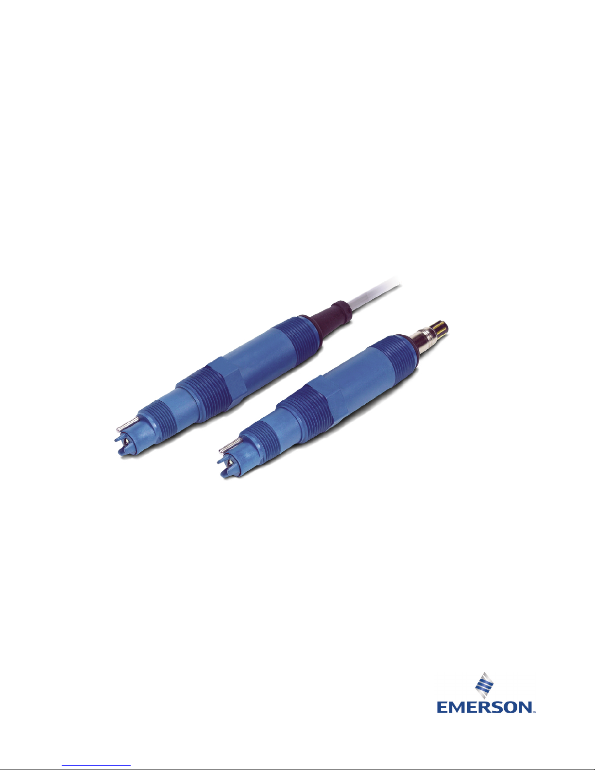
Figure 2-7: Rosemount 3900/3900VP with Preamplifier to Rosemount 56/1056/1057/1066
Transmitter Wiring
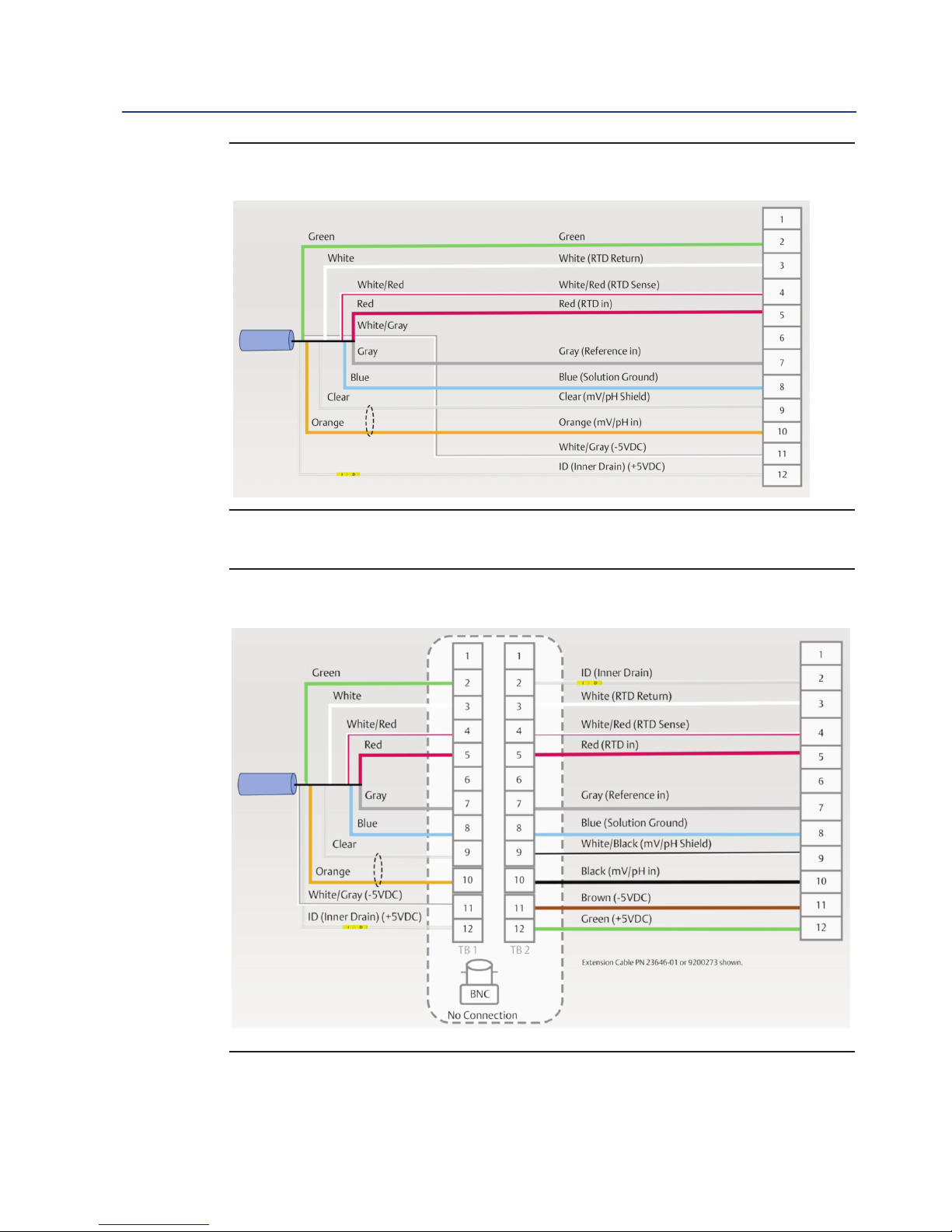
Figure 2-8: Rosemount 3900/3900VP with Preamplifier to Rosemount 56/1056/1057/1066
Transmitter, Junction Box without Preamplifier (PN 23550-00) Wiring
Page 15

Installation 9
Instruction Manual Section 2: Installation
LIQ-MAN-3900 April 2017
Figure 2-9: Rosemount 3900/3900VP without Preamplifier to Rosemount 56/1056/1057/1066
Transmitter Wiring
Figure 2-10: Rosemount 3900/3900VP without Preamplifier to Rosemount 56/1056/1057/1066
Transmitter, Junction Box with Preamplifier (PN 23555-00) Wiring
Page 16
10 Installation
Section 2: Installation Instruction Manual
April 2017 LIQ-MAN-3900
Figure 2-11: Rosemount 3900/3900VP with Preamplifier to Rosemount 5081
Transmitter Wiring
Figure 2-12: Rosemount 3900/3900VP with Preamplifier to Rosemount 5081 Transmitter,
Junction Box without Preamplifier (PN 23550-00) Wiring
Page 17

Installation 11
Instruction Manual Section 2: Installation
LIQ-MAN-3900 April 2017
Figure 2-13: Rosemount 3900/3900VP without Preamplifier to Rosemount 5081
Transmitter Wiring
Figure 2-14: Rosemount 3900/3900VP without Preamplifier to Rosemount 5081
Transmitter, Junction Box with Preamplifier (PN 23555-00) Wiring
Page 18

12 Installation
Section 2: Installation Instruction Manual
April 2017 LIQ-MAN-3900
Page 19

Calibration and Maintenance 13
Instruction Manual Section 3: Calibration and Maintenance
LIQ-MAN-3900 April 2017
Section 3: Calibration and Maintenance
3.1 pH Two Point Buffer Calibration
Select two stable buffer solutions, preferably pH 4.0 and 7.0 (pH buffers other than pH 4.0 and
pH 7.0 can be used as long as the pH values are at least two pH units apart).
1. Immerse sensor in the first buffer solution. Allow sensor to equilibrate to the buffer
temperature (to avoid errors due to temperature differences between the buffer solution
and sensor temperature) and wait for reading to stabilize. Value of buffer can now be
acknowledged by transmitter.
2. Once the first buffer has been acknowledged by the transmitter, rinse the buffer solution
off the sensor with distilled or deionized water.
3. Repeat the steps 1 and 2 using the second buffer solution.
4. The theoretical slope value, according to the Nernst equation for calculating pH, is
approximately 59.1 mV/pH. Over time the sensor will age, both in the process and in
storage, which will result in reduced slope values. To ensure accurate readings, it is
recommended that the electrode be replaced when the slope value falls below
47 to 49 mV/pH.
3.2 Recommended pH Sensor Standardization
For maximum accuracy, the sensor can be standardized on-line or with a process grab sample after
a buffer calibration has been performed and the sensor has been conditioned to the process.
Standardization accounts for the sensor junction potential and other interferences.
Standardization will not change the sensors slope, but will simply adjust the transmitter’s reading
to match that of the known process pH.
3.3 pH Electrode Maintenance
Electrodes should respond rapidly. Sluggishness, offsets, and erratic readings are indicators that
the electrodes may need cleaning or replacement.
1. To remove oil deposit, clean the electrode with a mild non-abrasive detergent.
2. To remove scale deposits, soak electrodes for 1 to 5 minutes in a 5% hydrochloric acid
solution.
3. Temperature effect on life expectancy: If glass electrode life expectancy is 100% at
77 °F (25 °C), then it will be approximately 25% at 176 °F (80 °C), and approximately 10%
at 212 °F (100°C).
A pH 7 buffer solution reads a mV value of approx. zero, and pH buffers read approximately ± 59.1 mV
f
or each pH unit above or below pH 7. Check the pH buffer manufacturer specifications for millivolt
values at various temperatures since it may affect the actual value of the buffer solution mV/pH value.
NOTICE
Page 20

14 Calibration and Maintenance
Section 3: Calibration and Maintenance Instruction Manual
April 2017 LIQ-MAN-3900
Hydrochloric acid is toxic and highly corrosive. Avoid skin contact; wear protective gloves. Use only in a
w
ell ventilated area. Do not inhale fumes. In case of an accident, consult a doctor immediately.
CAUTION
3.4 ORP Calibration
1. After making an electrical connection between the sensor and the instrument, obtain a
standard solution of saturated quinhydrone PN R508-8OZ (475mV). This can also be made
quite simply by adding a few crystals of quinhydrone to either pH 4 or pH 7 buffer.
Quinhydrone is only slightly soluble; therefore only a few crystals will be required.
2. Immerse the sensor in the standard solution. Allow 1-2 minutes for the ORP sensor to
stabilize.
3. Standardize the instrument to the solution value shown in the
Table 3-1 below. The
resulting potentials, measured with a clean platinum electrode and saturated KCl/AgCl
reference electrode, should be within +/- 20 millivolts of the value shown in the table below.
Solution temperature must be noted to ensure accurate interpretation of results. The ORP
value of saturated quinhydrone solution is not stable over long periods of time. Therefore,
these standards should be made up fresh each time they are used.
4. Remove the sensor from the buffer, rinse, and install in the process.
3.5 ORP Electrode Maintenance
Electrodes should respond rapidly. Sluggishness, offsets, and erratic readings are indicators that
the electrodes may need cleaning or replacement.
1. To remove oil deposit, clean the electrode with a mild non-abrasive detergent.
2. To remove scale deposits, soak electrodes for 1 to 5 minutes in a 5% hydrochloric acid
solution.
3 ORP (metallic) electrodes should be polished with moistened baking soda.
pH 4 Solution pH 7 Solution
Temperature °C 20 25 30 20 25 30
mV Potential 268 264 260 94 87 80
Table 3-1 ORP of Saturated Quinhydrone Solution (millivolts)
Page 21

Accessories 15
Instruction Manual Section 4: Accessories
LIQ-MAN-3900 April 2017
Section 4: Accessories
Part Number Description
24281-00 15 ft. cable with mating VP8 connector
24281-01 25 ft. cable with mating VP8 connector
2
4281-02
2
.5 ft. cable with mating VP8 connector
24281-03 50 ft. cable with mating VP8 connector
24281-04 100 ft. cable with mating VP8 connector
24281-05 4 ft. cable with mating VP8 connector
24281-06 10 ft. cable with mating VP8 connector
24281-07 20 ft. cable with mating VP8 connector
24281-08 30 ft. cable with mating VP8 connector
12707-00 Jet Spray Cleaner
23242-02 Insertion Mounting Adapter, 1.5" MNPT Process Connection, 1" x 3/4" FPT Sensor Adapter/Union Thread Size
24091-00 Low flow cell, 1" NPT Adapter
24091-02 Low flow cell, 3/4" NPT Adapter
23555-00 Weatherproof Junction Box, with Preamplifier
2002011 CPVC In-Line Tee, 1.5" Size, 1.0" Threaded Process Connection
11275-01 Handrail Mounting Assembly
9210012 pH 4.01 Buffer Solution, 16 oz
9210013 pH 6.86 Buffer Solution, 16 oz
9210014 pH 9.18 Buffer Solution, 16 oz
9200273 Conductor Extension Cable, Shielded and Unprepped (for use with Remote Junction Box)
SQP10077-LQD Low Flow Control Panel
Table 4-1 Accessories Information
Page 22

Section 4: Accessories Instruction Manual
April 2017 LIQ-MAN-3900
16 Accessories
Page 23

EC Declaration of Conformity 17
Instruction Manual EC Declaration of Conformity
LIQ-MAN-3900 April 2017
Note: Please see website for most recent Declaration.
Page 24

18 EC Declaration of Conformity
EC Declaration of Conformity Instruction Manual
April 2017 LIQ-MAN-3900
Page 25

FM Installation 19
Instruction Manual FM Installation
LIQ-MAN-3900 April 2017
Intrisicallly Safe Sensor Installation Drawing - FM
ANY FM APPROVED
ASSOCIATED APPARATUS
HAVING ENTITY PARAMETERS
NO
N-
H
AZARDOUS
(UNCLASSIFIED)
AREA
CLASS I, II, III, DIVISION 1, GROUPS A-G
T6 Ta = 60°C
SENSOR
ENTITY PARAMETERS
Ui = 13.1U, Ii = 358mA
Pi = 698 mW
Ci = 0.967 µF, Li = 0.1mH
1. NO REVISION TO THIS DRAWING IS PERMITTED WI THOUT
FM APPROVAL.
2. U
max
> U
t
; I
max
> I
t
; (C
i
OF ALL LOOPS + C CABLE) < C
a
;
(L
i
OF ALL LOOPS + L CABLE) < L
a
, P
max
OR P
i
> P
0.
3. SINGLE MULTI-CHANNEL
IS BARRIER OR APPARATUS MUST BE FM APPROVED,
4. SINGLE MULTI-CHANNEL
IS BARRIER OR APPARATUS MANUFACTURE'S
CONTROL DRAWI NGS MUST BE FOLLOWED WHEN INSTALLING THE SYSTEM.
IS BARRIER OR EQUIPMENT MAY BE INSTALLED WITHIN THE HAZARDOUS
(CLASSIFIED) LOCATION FOR WHICH IT IS APPROVED
.
5. INSTALLATION MUST BE IN ACCORDANCE WITH ARTICL
E 500 OF THE NEC
(ANSI/NFPA 70) AND ANSI/ISA RP 12.6.
WARNING: SUBSTITUTION OF COMPONENTS MAY IMPA
IR INTRINSIC SAFETY.
6. pH & AM PEROMETRIC SENSORS WITHOUT PREAM PS ARE SIMPLE APPARATUS.
ZONE
ZONE 0
7. CONTROL EQUIPMENT CONNECTED TO THE ASSOCIATED APPARATUS MUST
NOT USE OR GENERATE MORE THAN 250V.
RESISTANCE BETWEEN INTRINSICALLY SAFE GROUND AND EARTH GROUND
MUST BE LESS THAN OR EQUAL TO 1 OHM.
ANY
FM APPROVED TRANSMI TTER FOR
DIVISION 1 WITH INTRINSICALLY SAFE
OUTPUT PARAMETERS. THIS
FM
APPROVED DEVICE MUST BE INSTALLED
PER ITS INSTALLATION DRAWING.
FM
APPROVED EQUIPMENT (MAY BE
MULTIPLE DEVICES, NUMBER IS LIMITED
BY REQUIREMENTS TO MEET ALL OTHER
IS REQUIREMENTS FOR THE NETWORK)
WITH EQUIVALENT HAZARDOUS AREA
APPROVALS.
H
AZA RDOUS
(CL ASSI
F
IED)
AREA
INTRISICA LLY SA FE
9. pH/ORP SENSOR MODELS THAT MAY CONTAI N THE PREAMPLIFIER:
3900/VP
3500/VP
3300HT/VP
3400HT/VP
396/VP
396R/VP
396P/VP
398R/VP
399/VP
389/VP
385/385+
10. WARNING: TO PREVENT IGNITION OF FLAMMABLE OR COMBUSTIBLE
ATMOSPHERES, DISCONNECT POWER BEFORE SERVIC
ING.
11. THE ENTITY CONCEPT ALLOWS INTECONNECTI ON OF INTRINSICALLY SAFE
APPARATUS WITH ASSOCIATED APPARATUS WHEN THE FOLLOWING IS TRUE:
U
i
> U
o;
I
i
> I
o;
P
i
> P
o;
C
o
> C
i
+ C CABLE; L
o
> L
i
+ L CABLE.
12. COPY REVISIONS TO 1400332 TO pH/ORP SHIPPING MANUALS.
13 Ci INCLUDES THE CAPACITANCE OF 500 FEET OF SENSOR CABLE.
13
DWG NO.
1400332
8.
Page 26

LIQ-MAN-3900
Rev. G
April 2017
Emerson
8200 Market Blvd.
Chanhassen, MN 55317,
USA
Tel +1 800 999 9307
Fax +1 952 949 7001
Liquid.CSC@Emerson.com
Youtube.com/user/Rosemount
Twitter.com/Rosemount_News
Analyticexpert.com
facebook.com/Rosemount
©2017 Emerson. All rights reserved.
The Emerson logo is a trademark and service mark of Emerson Electric Co. Rosemount is a mark of
one of the Emerson family of companies. All other marks are the property of their respective
owners.
The contents of this publication are presented for information purposes only, and while effort has
been made to ensure their accuracy, they are not to be construed as warranties or guarantees,
express or implied, regarding the products or services described herein or their use or applicability.
All sales are governed by our terms and conditions, which are available on request. We reserve the
right to modify or improve the designs or specifications of our products at any time without notice.
www.Emerson.com/RosemountLiquidAnalysis
 Loading...