

Page 1
00825-0100-3900, Rev AA
Rosemount™ 3900/3900VP
General Purpose pH/ORP Sensors
Quick Start Guide
November 2020
Page 2

Quick Start Guide November 2020
Essential instructions
Read this page before proceeding!
Emerson designs, manufactures, and tests its products to meet many national and international
standards. Because these instruments are sophisticated technical products, you must properly install,
use, and maintain them to ensure they continue to operate within their normal specifications. You
must adhere to the following instructions and integrate them into your safety program when
installing, using, and maintaining Emerson's Rosemount™ products. Failure to follow the proper
instructions may cause any one of the following situations to occur: loss of life, personal injury,
property damage, damage to this instrument, and warranty invalidation.
• Read all instructions prior to installing, operating, and servicing the product.
• If this Quick Start Guide is not the correct one, call 1-800-854-8257 or 949-757-8500 to request
the correct Quick Start Guide. Save this Quick Start Guide for future reference.
• Follow all warnings, cautions, and instructions marked on and supplied with the product.
• Inform and educate your personnel in the proper installation, operation, and maintenance of the
product.
• Install equipment as specified in the installation instructions of the appropriate Quick Start Guide
and per applicable local and national codes. Connect all products to the proper electrical and
pressure sources.
• To ensure proper performance, use qualified personnel to install, operate, update, program, and
maintain the product.
• When replacement parts are required, ensure that qualified people use replacement parts
specified by Emerson. Unauthorized parts and procedures can affect the product's performance,
place the safe operation of your process at risk, and may result in fire, electrical hazards, or
improper operation.
• Ensure that all equipment doors are closed and protective covers are in place, except when
maintenance is being performed by qualified people, to prevent electrical shock and personal
injury.
Note
The information contained in this document is subject to change without notice.
WARNING
Hazardous area installation
Installations near flammable liquids or in hazardous areas must be carefully evaluated by on site
safety personnel.
To secure and maintain intrinsically safe installation, an appropriate transmitter/safety barrier/
sensor combination must be used. The installation system must be in accordance with the
governing approval agency (FM, CSA, or BASEEFA/CENELEC) hazardous area classification
requirements. Consult your transmitter Reference Manual for details.
Proper installation, operation, and servicing of this sensor in a hazardous area are entirely the
operator's responsibility.
2 Emerson.com/Rosemount
Page 3
November 2020 Quick Start Guide
WARNING
Pressure and temperature
Before removing the sensor, be absolutely certain that the process pressure is reduced to 0 psig
and the process temperature is lowered to a safe level.
Do not insert or retract retractable sensors when process pressures are in excess of 64 psig (542
kPa) for option 21 or 35 psig (343 kPa) for option 25.
WARNING
Corrosive substance
The solution used during calibration is an acid; handle it with care.
Follow the directions of the acid manufacturer.
Wear the proper protective equipment.
Do not let the solution come into contact with skin or clothing.
If contact with skin is made, immediately rinse with clean water.
WARNING
Physical access
Unauthorized personnel may potentially cause significant damage to and/or misconfiguration of end
users’ equipment. This could be intentional or unintentional and needs to be protected against.
Physical security is an important part of any security program and fundamental to protecting your
system. Restrict physical access by unauthorized personnel to protect end users’ assets. This is true for
all systems used within the facility.
CAUTION
Special conditions for safe use
All pH/ORP sensors have a plastic enclosure which must be cleaned with a damp cloth to avoid the
danger due to a buildup of electrostatic discharge.
CAUTION
Sensor/process application compatibility
The wetted sensor materials may not be compatible with process composition and operating
conditions.
Application compatibility is entirely the operator's responsibility.
Contents
Install........................................................................................................................................... 5
Calibrate and maintain............................................................................................................... 22
Accessories................................................................................................................................ 25
Quick Start Guide 3
Page 4

Quick Start Guide November 2020
Specifications.............................................................................................................................26
Rosemount pH/ORP sensor(s) product certifications..................................................................28
Declaration of Conformity..........................................................................................................35
China RoHS table........................................................................................................................37
Intrinsically safe sensor installation drawing - FM........................................................................38
4 Emerson.com/Rosemount
Page 5

November 2020 Quick Start Guide
1 Install
1.1 Storage
1. Emerson recommends storing electrodes in their original shipping
containers until needed.
2. Do not store at temperatures below 14 °F (-10 °C).
3. Store electrodes with a protective cap containing KCl solution
(PN 9210342).
4. For overnight storage, immerse the sensor in tap water or 4 pH
buffer solution.
5. pH glass electrodes slowly deteriorate in storage. There is no specific
expiration date. Follow the calibration procedures in Calibrate and
maintain to determine that the sensor calibrates properly.
1.2 Prepare electrode
Procedure
1. Remove electrode from shipping container.
2. Remove the protective boot covering the electrode bulb.
3. Rinse away salt film with clean water; then shake the electrode so
that the internal solution fills the bulb, thus removing any air trapped
there.
1.3
Quick Start Guide 5
Install sensor
Procedure
1. Wrap the sensor threads with six or seven turns of PTFE tape to
prevent leakage.
Do not over tighten the sensor into its receptacle.
2. Hand tighten the sensor and then tighten one or two turns with a
wrench.
Page 6
Quick Start Guide November 2020
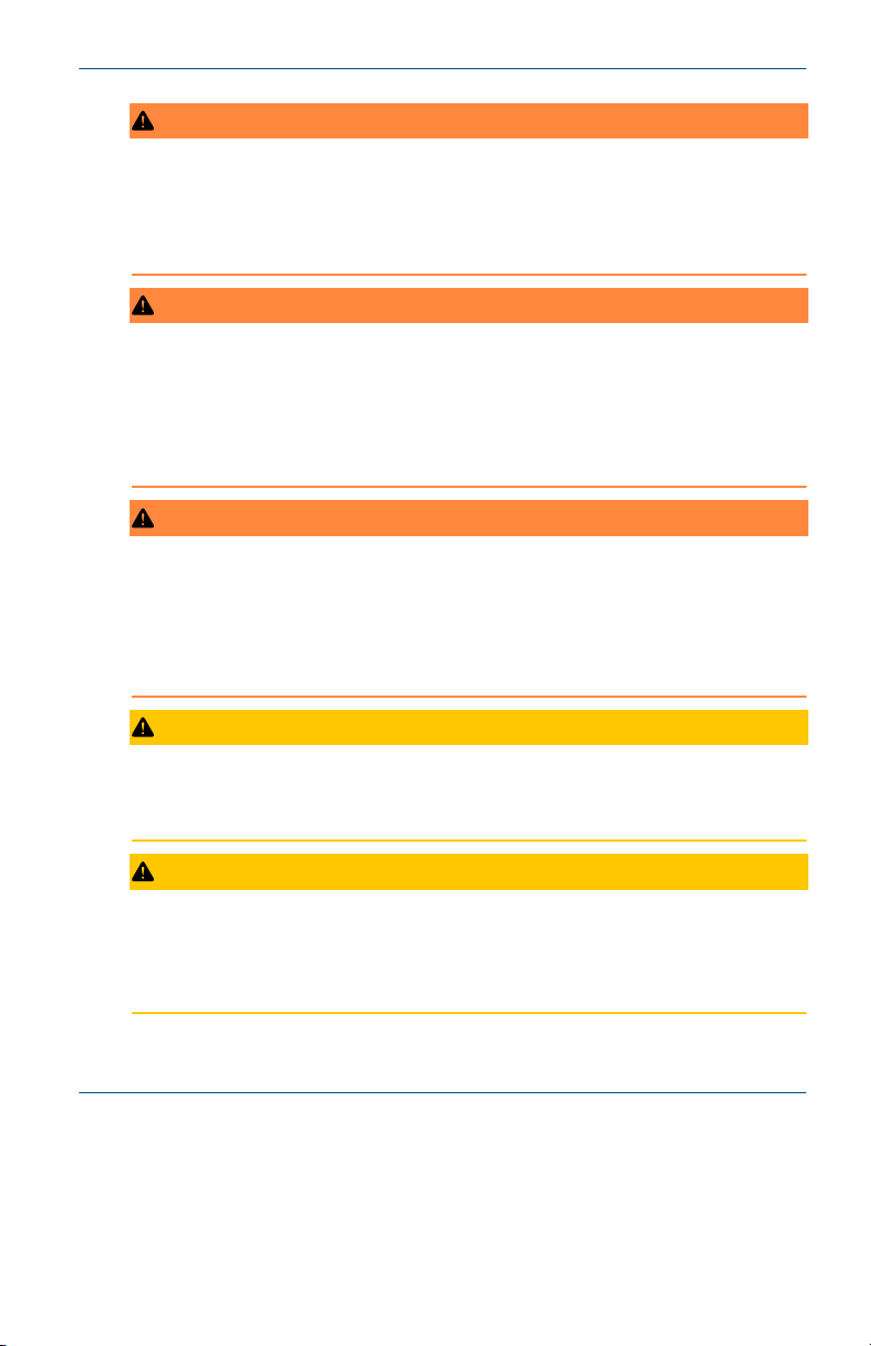
Figure 1-1: Sensor Orientation
Install sensor within 80 ° of vertical.
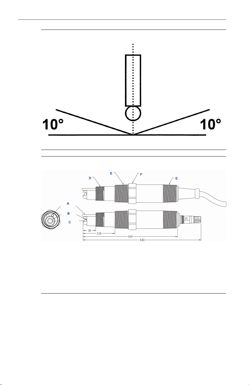
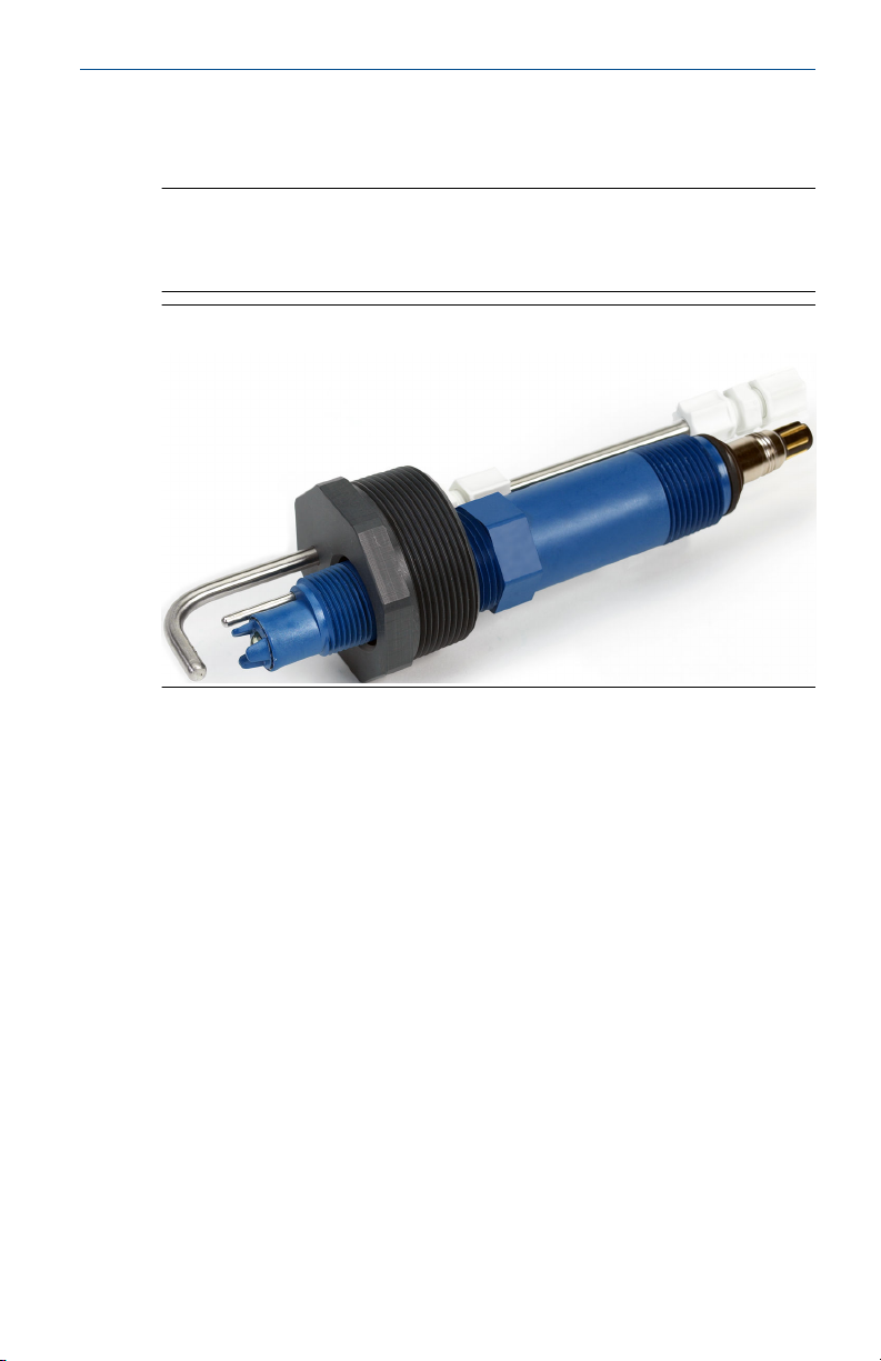
Figure 1-2: Rosemount 3900/3900VP Sensor Dimensions
A. Temperature comp solution ground
B. Reference junction
C. pH electrode
D. ¾-in. male national pipe thread (MNPT)
E. 1-in. MNPT
F. Wrench flats 1.30 in. across
6 Emerson.com/Rosemount
Page 7
November 2020 Quick Start Guide
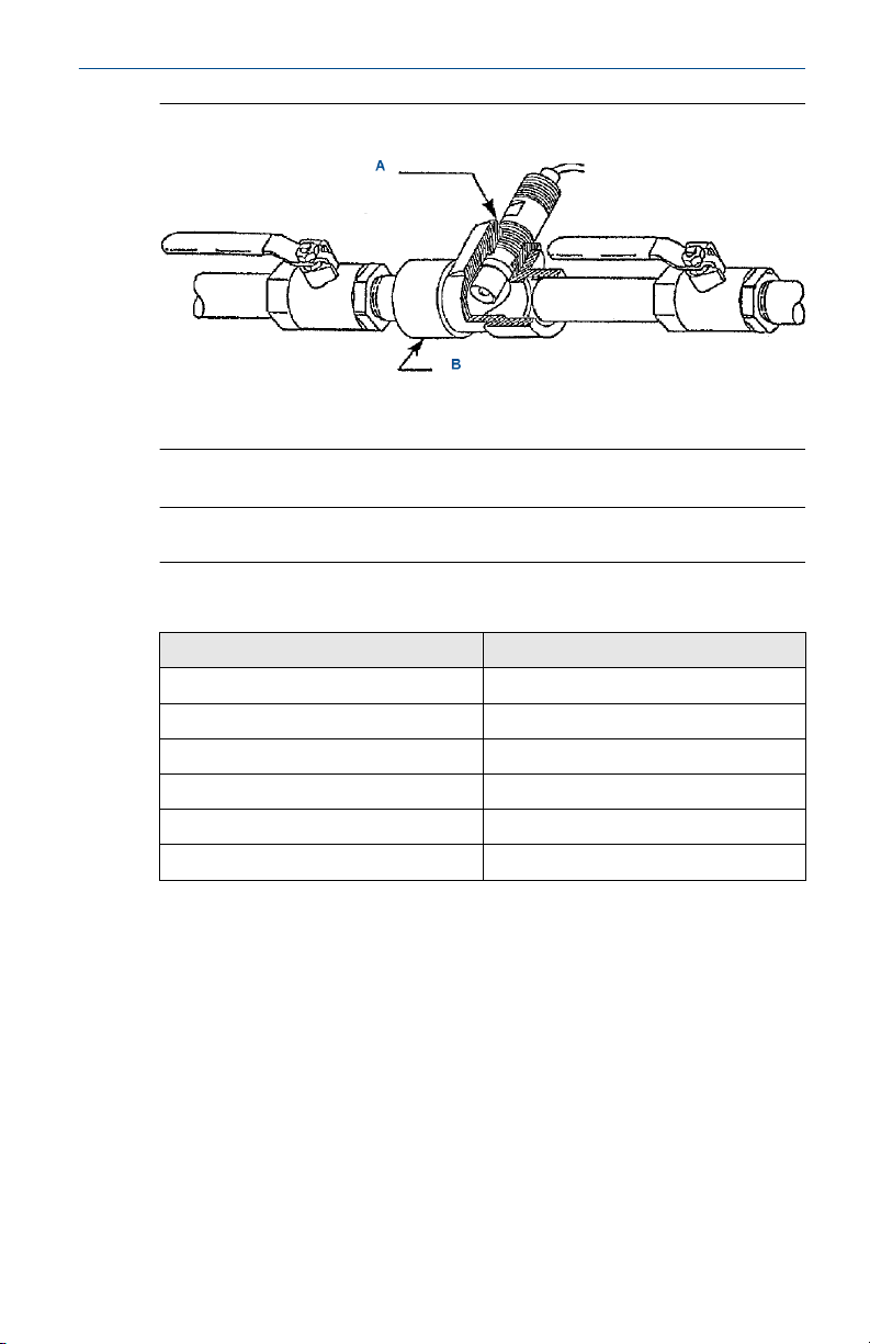
Figure 1-3: Mount
A. 1½-in. x 1 in. reducing bushing
B. 1½-in. pipe tee PN 2002011
Straight flow shown
Note
Install sensor at least ten degrees above the horizon.
Table 1-1: Horizontal Pipe Tee (PN 2002011) Pressure/Temperature
Ratings
psig (kPa) °F (°C)
150 (1136) 150 (65)
128 (984) 160 (71)
102 (805) 170 (77)
80 (653) 180 (82)
57 (494) 200 (93)
48 (432) 210 (99)
Quick Start Guide 7
Page 8
Quick Start Guide November 2020
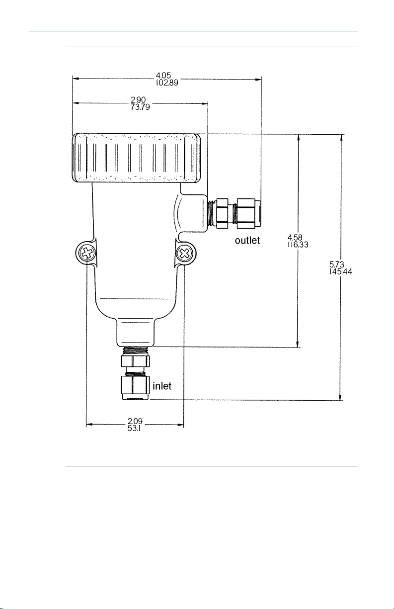
Figure 1-4: Low Flow Cell PN 24091-00/24091-02
Inlet and outlet connections are stainless steel and take ¼-in. OD tubing.
Flow cell is polycarbonate with ¼-in. female national pipe thread (FNPT)
fittings.
Wetted materials
Body and nut: polyester/polycarbonate
Fittings: 316 stainless steel
Seals: silicone
Flow cell ratings
Temperature: 32 to 158 °F (0 to 70 °C)
Max. pressure: 90 pisg (721 kPa)
8 Emerson.com/Rosemount
Page 9

November 2020 Quick Start Guide
Flow rate: 2 to 5 gph (7.6 to 18.9 LPH)
Sensor threaded
connection
24091-00: 1-in. national pipe thread (NPT) adapter
24091-02: ¾-in. NPT adapter
Quick Start Guide 9
Page 10
Quick Start Guide November 2020
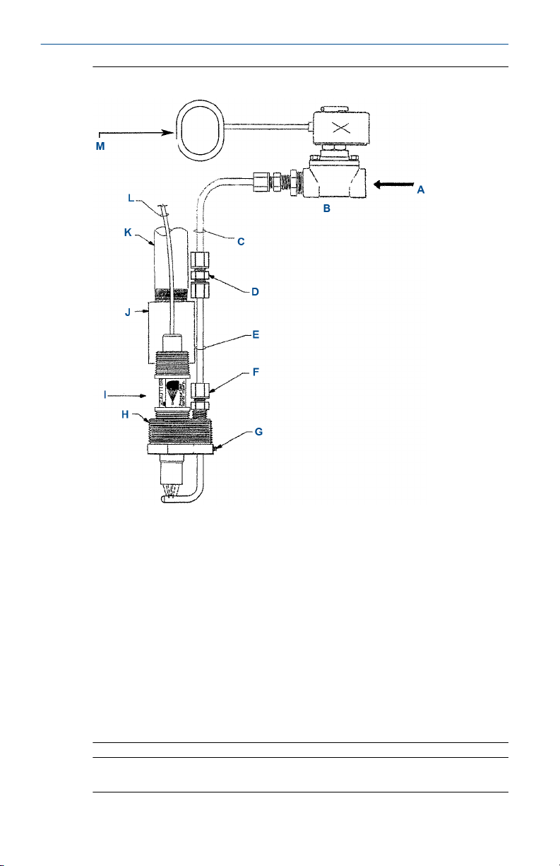
Figure 1-5: Jet Spray Cleaner
A. Cleaning solution by others
B. Solenoid valve or manual valve (supplied by others)
C. Corrosion resistant tubing (supplied by others)
D. Polypropylene ¼-in. compression fitting
E. ¼-in. 316 stainless steel
F. ¼-in. polypropylene
G. Stainless set screw for adjustable spray nozzle height
H. 2-in. NPT threads
I. Sensor
J. 1-in. PVC coupling for submersible applications (supplied by others)
K. 1-in. PVC or stainless conduit (supplied by others)
L. Cable
M. Timer supplied by others or use timer feature in Rosemount instrument
Note
Sensor must be installed at least 10 degrees above the horizon.
10 Emerson.com/Rosemount
Page 11
November 2020 Quick Start Guide
The jet spray cleaner eliminates routine, manual sensor maintenance by
cleaning the sensor with water or compressed air. Use a solenoid valve to
control flow through the cleaner.
Note
You can alos use the jet spray cleaner with the handrail mounting assembly
(PN 11275-01, not shown) or mount it through the conduit as shown in
Figure 1-6.
Figure 1-6: Jet Spray Cleaner with pH Sensor
Quick Start Guide 11
Page 12
Quick Start Guide November 2020
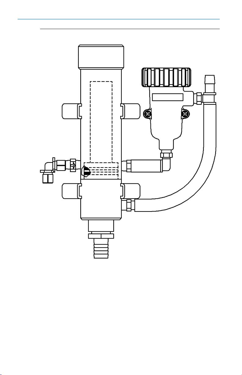
Figure 1-7: Low Flow Panel: PN SQP10077-LQD
12 Emerson.com/Rosemount
Page 13

November 2020 Quick Start Guide
Table 1-2: Low Flow Panel Specifications
Inlet flow 3-80 gph (11.4 - 304 L/hr)
Inlet pressure 3 - 65 psig (122-549 kPa)
Temperature 32 to 122 °F (0 to 50 °C)
(1) The minimum inlet pressure is required to open a check valve, which prevents
the flow cell from draining if sample flow is lost. Removing the check valve
lowers the inlet pressure requirement to a few feet of water head.
Quick Start Guide 13
(1)
Page 14

Quick Start Guide November 2020
1.4 Wiring
For additional wiring information on this product, including sensor
combinations not shown here, please refer to Liquid Transmitter Wiring
Diagrams.
Figure 1-8: Rosemount 3900/3900VP with Preamplifier to Rosemount
56/1056/1057/1066 Transmitter Wiring
Table 1-3: Rosemount 3900/3900VP with Preamplifier to Rosemount
56/1056/1057/1066 Transmitter Wiring
Wire function Wire color Connects to
Earth ground Green Ground
Resistance temperature
device (RTD) return
RTD sense White/red RTD sense/sense
RTD in Red RTD in
Solution ground Blue Ground/solution ground
+5 Vdc Inner drain +5 Vdc/+V sensor
-5 Vdc White/gray -5 Vdc/-V sensor
mV/pH shield Clear pH shield/shield/guard
mV/pH in Orange pH/pH in
Reference in Gray Reference/reference in
White RTD return/return
14 Emerson.com/Rosemount
Page 15

November 2020 Quick Start Guide
Figure 1-9: Rosemount 3900/3900VP with Preamplifier to Rosemount
56/1056/1057/1066 Transmitter, Junction Box without Preamplifier (PN
23550-00) Wiring
Table 1-4: Rosemount 3900/3900VP with Preamplifier to Rosemount
56/1056/1057/1066 Transmitter, Junction Box without Preamplifier
(PN 23550-00) Wiring
Wire color (sensor to
junction box)
N/A 1 N/A N/A
Green 2 Inner drain Earth ground
White 3 White RTD return
White/red 4 White/red RTD sense
Red 5 Red RTD in
N/A 6 N/A N/A
Gray 7 Gray Reference in
Blue 8 Blue Solution ground
Clear 9 White/black mV/pH shield
Orange 10 Black mV/pH in
White/gray 11 Brown -5 Vdc
Inner drain 12 Green +5 Vdc
Quick Start Guide 15
Junction box
terminal number
Wire color (junction
box to transmitter)
Transmitter terminal
Page 16

Quick Start Guide November 2020
Figure 1-10: Rosemount 3900/3900VP without Preamplifier to
Rosemount 56/1056/1057/1066 Transmitter Wiring
Table 1-5: Rosemount 3900/3900VP without Preamplifier to Rosemount
56/1056/1057/1066 Transmitter Wiring
Wire function Wire color Connects to
Inner drain No connection N/A
Earth ground Green Ground
RTD return White RTD return/return
RTD sense White/red RTD sense/sense
RTD in Red RTD in
N/A N/A -5 Vdc/-V sensor
N/A N/A +5 Vdc/+V sensor
Solution ground Blue Ground/solution ground
mV/pH shield Clear pH shield/shield/guard
mV/pH in Orange pH/pH in
Reference shield White/gray Reference shield/shield/guard
Reference Gray Reference/reference in
16 Emerson.com/Rosemount
Page 17

November 2020 Quick Start Guide
Figure 1-11: Rosemount 3900/3900VP without Preamplifier to
Rosemount 56/1056/1057/1066 Transmitter, Junction Box with
Preamplifier (PN 23555-00) Wiring
Table 1-6: Rosemount 3900/3900VP without Preamplifier to Rosemount
56/1056/1057/1066 Transmitter, Junction Box without Preamplifier
(PN 23555-00) Wiring
Wire color (sensor to
junction box
Inner drain N/A N/A No connection
N/A 1 N/A N/A
Green 2 Clear Earth ground
White 3 White RTD return
White/red 4 White/red RTD sense
Red 5 Red RTD in
White/gray 6 White/gray Reference shield
Gray 7 Gray Reference in
Blue 8 Blue Solution ground
Clear 9 White/black mV/pH shield
Orange 10 Black mV/pH in
N/A 11 Brown -5 Vdc
N/A 12 Green +5 Vdc
Quick Start Guide 17
Junction box
terminal number
Wire color (junction
box to transmitter)
Wire function
Page 18

Quick Start Guide November 2020
Figure 1-12: Rosemount 3900/3900VP with Preamplifier to Rosemount
5081 Transmitter Wiring
Table 1-7: Rosemount 3900/3900VP with Preamplifier to Rosemount 5081
Transmitter Wiring
Wire color Wire function Terminal block number
N/A N/A 1
Green N/A Ground
White RTD return 3
White/red RTD sense 4
Red RTD in 5
N/A N/A 6
Gray Reference in 7
Blue Solution ground 8
Clear mV/pH shield 9
Orange mV/pH in 10
White/gray -5 Vdc 11
Inner drain +5 Vdc 12
18 Emerson.com/Rosemount
Page 19

November 2020 Quick Start Guide
Figure 1-13: Rosemount 3900/3900VP with Preamplifier to Rosemount
5081 Transmitter, Junction Box without Preamplifier (PN 23550-00)
Wiring
Table 1-8: Rosemount 3900/3900VP with Preamplifier to Rosemount 5081
Transmitter, Junction Box without Preamplifier (PN 23550-00) Wiring
Wire color (sensor to
junction box)
N/A 1 N/A N/A
N/A 2 N/A Ground
White 3 White RTD return
White/red 4 White/red RTD sense
Red 5 Red RTD in
N/A 6 N/A N/A
Gray 7 Gray Reference in
Blue 8 Blue Solution ground
Clear 9 White/black mV/pH shield
Orange 10 Black mV/pH in
White/gray 11 Brown -5 Vdc
Inner drain 12 Green +5 Vdc
Quick Start Guide 19
Junction box
terminal number
Wire color (junction
box to terminal
block)
Wire function
Page 20

Quick Start Guide November 2020
Figure 1-14: Rosemount 3900/3900VP without Preamplifier to
Rosemount 5081 Transmitter Wiring
Table 1-9: Rosemount 3900/3900VP without Preamplifier to Rosemount 5081
Transmitter Wiring
Wire color Wire function Terminal block number
Inner drain No connection N/A
Green N/A Ground
White RTD return 3
White/red RTD sense 4
Red RTD in 5
White/gray Reference shield 6
Gray Reference in 7
Blue Solution ground 8
Clear mV/pH shield 9
Orange mV/pH in 10
N/A N/A 11
N/A N/A 12
20 Emerson.com/Rosemount
Page 21

November 2020 Quick Start Guide
Figure 1-15: Rosemount 3900/3900VP without Preamplifier to
Rosemount 5081 Transmitter, Junction Box with Preamplifier (PN
23555-00) Wiring
Table 1-10: Rosemount 3900/3900VP without Preamplifier to Rosemount 5081
Transmitter, Junction Box with Preamplifier (PN 23555-00) Wiring
Wire color (sensor to
junction box)
Inner drain (no
connection)
Green 2 Clear Ground
White 3 White RTD return
White/red 4 White/red RTD sense
Red 5 Red RTD in
White/gray 6 White/gray Reference shield
Gray 7 Gray Reference in
Blue 8 Blue Solution ground
Clear 9 White/black mV/pH shield
Orange 10 Black mV/pH in
N/A 11 Brown -5 Vdc
N/A 12 Green +5 Vdc
Quick Start Guide 21
Junction box
terminal number
1 N/A N/A
Wire color (junction
box to terminal
block)
Wire function
Page 22

Quick Start Guide November 2020
2 Calibrate and maintain
2.1 Calibrate pH two point buffer
Prerequisites
Select two stable buffer solutions, preferably pH 4.0 and 7.0 (pH buffers
other than pH 4.0 and pH 7.0 can be used as long as the pH values are at
least two pH units apart).
NOTICE
A pH 7 buffer solution reads an mV value of approximately zero, and pH
buffers read approximately ±59.1 mV for each unit above or below pH 7.
Check the pH buffer manufacturer specifications for millivolt values at
various temperatures since it may affect the actual value of the buffer
solution mV/pH value.
Procedure
1. Immerse sensor in the first buffer solution. Allow sensor to
equilibrate to the buffer temperature (to avoid errors due to
temperature differences between the buffer solution and sensor
temperature) and wait for reading to stabilize.
The transmitter can now acknowledge the value of the buffer.
2. Once the transmitter has acknowledged the first buffer, rinse the
buffer solution off the sensor with distilled or deionized water.
3. Repeat Step 1 and Step 2 using the second buffer solution.
The theoretical slope value, according to the Nernst equation for calculating
pH, is approximately 59.1 mV/pH. Over time the sensor will age, both in the
process and in storage, which will result in reduced slope values. To ensure
accurate readings, Emerson recommends that you replace the electrode
when the slope value falls below 47 to 49 mV/pH.
2.2
Recommended pH standardization
For maximum accuracy, standardize the sensor on-line or with a process
grab sample after performing a buffer calibration and conditioning the
sensor to the process.
Standardization accounts for the sensor junction potential and other
interferences. Standardization will not change the sensor's slope, but will
simply adjust the transmitter's reading to match that of the known process
pH.
22 Emerson.com/Rosemount
Page 23

November 2020 Quick Start Guide
2.3 Maintain pH electrodes
Electrodes should respond rapidly. Sluggishness, offsets, and erratic
readings are indicators that the electrodes may need cleaning or
replacement.
1. To remove oil deposits, clean the electrodes with a mild non-abrasive
detergent.
2. To remove scale deposits, soak electrodes for one to five minutes in a
5 percent hydrochloric acid solution.
3. Temperature effect on life expectancy: If glass electrode life
expectancy is 100 percent at 77 °F (25 °C), then it will be
approximately 25 percent at 176 °F (80 °C), and approximately 10
percent at 212 °F (100 °C).
WARNING
CORROSIVE SUBSTANCE
Hydrochloric acid is toxic and highly corrosive.
Avoid skin contact.
Wear protective gloves.
Use only in a well-ventilated area.
Do not inhale fumes.
In case of an accident, consult a doctor immediately.
2.4 Calibrate oxidation reduction potential (ORP)
Prerequisites
After making an electrical connection between the sensor and the
transmitter, obtain a standard solution of saturated quinhydrone
PN R508-8OZ (460 ± 10 mV). You can also make the solution by simply
adding a few crystals of quinhydrone to either pH 4 or pH 7 buffer.
Quinhydrone is only slightly soluble; therefore only a few crystals are
required.
Procedure
1. Immerse the sensor in the standard solution. Allow one to two
minutes for the ORP sensor to stabilize.
2. Standardize the transmitter to the solution value shown in Table 2-1.
The resulting potentials, measured with a clean platinum electrode
and saturated KCl/AgCl reference electrode, should be within ±20
mV of the value shown in Table 2-1. Note solution temperature to
ensure accurate interpretation of results. The ORP value of saturated
Quick Start Guide 23
Page 24

Quick Start Guide November 2020
quinhydrone solution is not stable over long periods of time.
Therefore, make these standards fresh each time they are used.
Table 2-1: ORP of Saturated Quinhydrone Solution (Millivolts)
pH 4 solution pH 7 solution
Temperature:
°F (°C)
mV potential 168 264 260 94 87 80
68 (20) 77 (25) 86 (30) 68 (20) 77 (25) 86 (30)
3. Remove the sensor from the buffer, rinse, and install in the process.
2.5 Maintain oxidation reduction potential (ORP) sensors
Electrodes should respond rapidly. Sluggishness, offsets, and erratic
readings are indicators that the electrodes may need to be cleaned or
replaced.
1. To remove oil deposits, clean the electrode with a mild non-abrasive
detergent.
2. To remove scale deposits, soak electrodes for one to five minutes in a
5 percent hydrochloric acid solution.
3. Polish ORP (metallic) electrodes with moistened baking soda.
24 Emerson.com/Rosemount
Page 25

November 2020 Quick Start Guide
3 Accessories
Table 3-1: Accessories
Part number Description
11275-01 Handrail mounting assembly
12707-00 Jet spray cleaner
2002011 CPVC flow-through tee, 1½-in. national pipe thread
23242-02 Mounting adapter, 1½-in. insertion, 1 x ¾-in.
23555-00 Junction box, Rosemount 54/5081/1055/Xmt
24091-00 Cell, low flow, ¼-in. inlet and outlet
33894-00 Adapter, 1-in. NPT low flow cell
24281-00 15-ft. (4.6 m) VP8 cable
24281-01 25-ft. (7.6 m) VP8 cable
24281-02 2.5-ft. (0.8 m) VP8 cable
24281-03 50-ft. (15.2 m) VP8 cable
24281-04 100-ft. (30.5 m) VP8 cable
24281-05 4-ft. (1.2 m) VP8 cable
24281-06 10-ft. (3 m) VP8 cable
24281-07 20-ft. (6.1 m) VP8 cable
24281-08 30-ft. (9.1 m) VP8 cable
9200273 Extension cable, 11-conduit, shielded, unprepped, per
9210012 Buffer solution, pH 4.01, 16 oz. (473 ml)
9210013 Buffer solution, pH 6.86, 16 oz. (473 ml)
9210014 Buffer solution, pH 9.18, 16 oz. (473 ml)
SQP10077-LQD Low flow panel
R508-8OZ Oxidation reduction potential (ORP) calibration
(NPT) process connection
compatible preamplifier
foot
standard 460 ± 10 mV
Quick Start Guide 25
Page 26

Quick Start Guide November 2020
4 Specifications
Measurements and
ranges
Percent linearity over pH
range
Materials of construction
Sensor body
O-ring
ORP electrode
Solution ground
Reference junction
pH: 0 - 14
Oxidation reduction potential (ORP): -1500
mV to +1500 mV
Range Linearity
0-7 97%
1-7 98%
4-7 98%
7-10 99%
7-12 97%
7-13 96%
7-14 95%
Ryton® polyphenylene sulfide (PPS)
EPDM
Glass, platinum
Stainless steel
PFTE
Maximum pressure
100 psig (790 kPa) at 212 °F (100 °C)
CRN rating: 60 psig (413.7 kPa) to 212 °F (100 °C)
Operating temperature
14 to 212 °F (-10 to 100 °C)
Automatic temperature compensation: 14 to 212 °F (-10 to 100 °C)
Conductivity
Responds to changes in pH at a minimum conductivity of 0.1 µS/cm when
used with the low flow panel (PN SQP10077-LQD). The sample flow rate
must be controlled to 2 gph (7.6 L/hr).
26 Emerson.com/Rosemount
Page 27

November 2020 Quick Start Guide
Process connections
Front facing: ¾-in. and 1-in. male national pipe thread (MNPT)
Rear facing: 1-in. MNPT
Weight / shipping weight
1 lb./2 lb. (0.45 kg/0.9 kg)
Integral cable
32-ft. (10 m) cable with integral preamp
15-ft. (4.7 m) cable without preamp
VP8 cable
Use 24281-XX, 2.5 ft. (0.8 m) to 100 ft. (31 m) (see Accessories).
NOTICE
The Rosemount 3900/3900VP sensor responds to changes in pH at a
minimum conductivity of 0.1 µS.cm in deionized water when used with low
flow panel (PN SQP10077-LQD). Sample flow rate must be controlled to 7.6
L/hr (2 gph). The offset is approximately -0.2 pH after three months at
ambient temperature.
Quick Start Guide 27
Page 28

Quick Start Guide November 2020
5 Rosemount pH/ORP sensor(s) product
certifications
Rev 0.5
5.1 European directive information
A copy of the EU Declaration of Conformity can be found at the end of the
Quick Start Guide. The most recent revision of the EU Declaration of
Conformity can be found at Emerson.com/Rosemount.
5.2 Ordinary location certification
As standard, the transmitter has been examined and tested to determine
that the design meets the basic electrical, mechanical, and fire protection
requirements by a nationally recognized test laboratory (NRTL) as accredited
by the Federal Occupational Safety and Health Administration (OSHA).
5.3 Installing equipment in North America
The US National Electrical Code® (NEC) and the Canadian Electrical Code
(CEC) permit the use of Division marked equipment in Zones and Zone
marked equipment in Divisions. The markings must be suitable for the area
classification, gas, and temperature class. This information is clearly defined
in the respective codes.
5.4
USA
5.4.1 FM Intrinsic Safety
Certificate
Standards
Markings
Specific Conditions for Safe Use (X):
1. Sensors with Model 1700702 preamplifier:
28 Emerson.com/Rosemount
FM17US0198X
FM Class 3600:1998, FM Class 3610:2010, FM Class 3611:
2004, FM Class 3810: 2005
IS/I,II,III/1/ABCDEFG/T6 Ta = –20 °C to 60 °C
I/0/AEx ia IIC/T6 Ta = –20 °C to 60 °C
NI/I/2/ABCD/T6 Ta = –20 °C to 60 °C
S/II,III/2/EFG/T6 Ta = –20 °C to 60 °C
a. Model 385+-a-b-c. Triple junction pH/ORP sensor
b. Model 389-a-b-c-d-e. pH/ORP sensor
c. Model 389VP-a-b-c-d. pH/ORP sensor
d. Model 396VP-a-b-c-d. Submersion/insertion pH/ORP sensor
Page 29

November 2020 Quick Start Guide
e. Model 396P-a-b-c-d-e. Submersion/insertion pH/ORP sensor
f. Model 396PVP-a-b-c-d-e. Submersion/insertion pH/ORP
sensor
g. Model 396RVP-a-b-c-d-e. Retraction/submersion/insertion
pH/ORP sensor
h. Model 398RVP-a-b-c-d-e-f. pH/ORP sensor
i. Model 3200HP-00. High purity water pH sensor
j. Model 3300HTVP-a-b-c-d. High performance pH and ORP
sensor
k. Model 3400HTVP-a-b-c-d-e. High performance pH and ORP
sensor
l. 3500P-a-b-c-d-e-f. High performance pH and ORP sensor
m. 3500VP-a-b-c-d-e-f. High performance pH and ORP sensor
n. Model 3900-a-b-c. General purpose pH/ORP sensor
o. Model 3900VP-a-b. General purpose pH/ORP sensor
The polymeric surface of all the apparatus listed above may store
electrostatic charge and become a source of ignition. Clean surface
should only be done with a damp cloth.
2. Sensors without Model 1700702 preamplifier (simple apparatus):
a. Model 385-a-b-c-d-e. Retractable pH/ORP sensor
b. Model 385+-a-b-c Triple junction pH/ORP sensor
c. Model 389-a-b-c-d-e. pH/ORP sensor
d. Model 389VP-a-b-c. pH/ORP sensor
e. Model 396-a-b-c. Submersion/insertion pH sensor
f. Model 396VP-a-b. Submersion/insertion pH sensor
g. Model 396P-a-b-c-d-e. Submersion/insertion pH/ORP sensor
h. Model 396PVP-a-b-c-d. Submersion/insertion pH/ORP sensor
i. Model 396R-a-b-c-d-e. Retraction/submersion/insertion
pH/ORP sensor
j. Model 396RVP-a-b-c-d. Retraction/submersion/insertion
pH/ORP sensor
k. Model 397-a-b-c-d-e. pH sensor
l. Model 398-a-b-c-d-e. pH/ORP sensor
Quick Start Guide 29
Page 30

Quick Start Guide November 2020
m. Model 398VP-a-b-c. pH/ORP sensor
n. Model 398R-a-b-c-d-e-f. pH/ORP sensor
o. Model 398RVP-a-b-c-d-e-f. pH/ORP sensor
p. Model 3200HP-00. High purity water pH sensor
q. Model 3300HT-a-b-c-d. High performance pH and ORP sensor
r. Model 3300HTVP-a-b-c-d. High performance pH and ORP
sensor
s. Model 3400HT-a-b-c-d-e-f. High performance pH and ORP
sensor
t. Model 3400HTVP-a-b-c-d-e-f. High performance pH and ORP
sensor
u. Model 3500P-a-b-c-d-e-f. High performance pH and ORP
sensor
v. Model 3500VP-a-b-c-d-e-f. High performance pH and ORP
sensor
w. Model 3800-a. Autoclaveable and steam sterilizable pH
sensors
x. Model 3800VP-a. Autoclaveable and steam sterilizable pH
sensors
y. Model 3900-a-b-c. General purpose pH/ORP sensor
z. Model 3900VP-a-b. General purpose pH/ORP sensor
The polymeric surface of all the apparatus listed above may store
electrostatic charge and become a source of ignition. Clean surface
should only be done with a damp cloth.
5.4.2 CSA Intrinsic Safety
Certificate
Standards
Markings
30 Emerson.com/Rosemount
70164066
C22.2 No 0-10, C22.2 No 0.4-M2004, C22.2 No 94-M1991,
C22.2 No 142 – M1987, C22.2 No 157-M1992, CAN/CSA
E60079-0:07, CAN/CSA E60079-11:02, UL 50-11th Ed, UL
508-17th Ed, UL 913-7th Ed, UL 60079-0: 2005, UL 60079-11:
2002
Preamplifier assembly:
Class I, Division 1, Groups ABCD; Class II, Division 1, Groups
EFG; Class III; Class I, Division 2, Groups ABCD; ambient
temperature rating –20 °C to +60 °C; Ex ia IIC; T6: Class I, Zone
0, AEx ia IIC ; T6
Page 31

November 2020 Quick Start Guide
Sensor apparatus with preamplifier:
Class I, Division 1, Groups ABCD; Class II, Division 1, Groups
EFG; Class III; Class I, Division 2, Groups ABCD; ambient
temperature rating –20 °C to +60 °C; Ex ia IIC; T6: Class I, Zone
0, AEx ia IIC ; T6
Sensor apparatus:
Class I, Division 1, Groups ABCD; Class II, Division 1, Groups
EFG; Class III; Class I, Division 2, Groups ABCD; Ex ia IIC; T6;
ambient temperature rating –20 °C to +60 °C: (simple
apparatus)
5.5 Canada
5.5.1 CSA Intrinsic Safety
Certificate
Standards
Markings
70164066
C22.2 No 0-10, C22.2 No 0.4-M2004, C22.2 No 94-M1991,
C22.2 No 142 – M1987, C22.2 No 157-M1992, CAN/CSA
E60079-0:07, CAN/CSA E60079-11:02, UL 50-11th Ed, UL
508-17th Ed, UL 913-7th Ed, UL 60079-0: 2005, UL 60079-11:
2002
Preamplifier assembly:
Class I, Division 1, Groups ABCD; Class II, Division 1, Groups
EFG; Class III; Class I, Division 2, Groups ABCD; ambient
temperature rating –20 °C to +60 °C; Ex ia IIC; T6: Class I, Zone
0, AEx ia IIC ; T6
Sensor apparatus with preamplifier:
Class I, Division 1, Groups ABCD; Class II, Division 1, Groups
EFG; Class III; Class I, Division 2, Groups ABCD; ambient
temperature rating –20 °C to +60 °C; Ex ia IIC; T6: Class I, Zone
0, AEx ia IIC ; T6
Sensor apparatus:
Class I, Division 1, Groups ABCD; Class II, Division 1, Groups
EFG; Class III; Class I, Division 2, Groups ABCD; Ex ia IIC; T6;
ambient temperature rating –20 °C to +60 °C: (simple
apparatus)
5.6 Europe
5.6.1 ATEX Intrinsic Safety
Certificate
Standards
Markings
Quick Start Guide 31
Baseefa10ATEX0156
EN 60079-0: 2012+A11: 2013, EN 60079-11: 2012
pH/ORP sensors with no preamplifier fitted
II 1 G Ex ia IIC T4 Ga (–20 °C to +60 °C)
Page 32

Quick Start Guide November 2020
pH sensors with integral smart preamplifier fitted
II 1 G Ex ia IIC T4 Ga (–20 °C to +60 °C)
ORP sensors with integral standard preamplifier fitted
II 1 G Ex ia IIC T4 Ga (–20 °C to +80 °C)
Ex ia IIC T5 Ga (–20 °C to +40 °C)
pH sensors with integral standard preamplifier fitted
II 1 G Ex ia IIC T4 Ga (–20 °C to +80 °C)
Ex ia IIC T5 Ga (–20 °C to +40 °C)
Specific Conditions for Safe Use (X):
1. All pH/ORP sensor models with a plastic enclosure or exposed plastic
parts may provide an electrostatic ignition hazard and must only be
cleaned with a damp cloth to avoid the danger of ignition due to
build-up of electrostatic charge.
2. All pH/ORP sensor models with a metallic enclosure may provide a
risk of ignition by impact or friction. Care should be taken during
installation to protect the sensor from the risk.
3. External connections to the sensor must be suitably terminated and
provide a degree of protection of at least IP20.
4. All pH/ORP sensor models are intended to be in contact with the
process fluid and may not meet the 500V r.m.s. test to earth. This
must be taken into consideration at installation.
5.7
International
5.7.1 IECEx Intrinsic Safety
Certificate
Standards
Markings
32 Emerson.com/Rosemount
IECEx BAS 10.0083X
IEC 60079-0: 2011, IEC 60079-11: 2011
pH/ORP sensors with no preamplifier fitted
Ex ia IIC T4 Ga (–20 °C to +60 °C)
pH sensors with integral smart preamplifier fitted
Ex ia IIC T4 Ga (–20 °C to +60 °C)
ORP sensors with integral standard preamplifier fitted
Ex ia IIC T4 Ga (–20 °C to +80 °C)
Ex ia IIC T5 Ga (–20 °C to +40 °C)
pH sensors with integral standard preamplifier fitted
Ex ia IIC T4 Ga (–20 °C to +80 °C)
Ex ia IIC T5 Ga (–20 °C to +40 °C)
Page 33

November 2020 Quick Start Guide
Specific Conditions for Safe Use (X):
1. All pH/ORP sensor models with a plastic enclosure or exposed plastic
parts may provide an electrostatic ignition hazard and must only be
cleaned with a damp cloth to avoid the danger of ignition due to
build-up of electrostatic charge.
2. All pH/ORP sensor models with a metallic enclosure may provide a
risk of ignition by impact or friction. Care should be taken during
installation to protect the sensor from the risk.
3. External connections to the sensor must be suitably terminated and
provide a degree of protection of at least IP20.
4. All pH/ORP sensor models are intended to be in contact with the
process fluid and may not meet the 500V r.m.s. test to earth. This
must be taken into consideration at installation.
5.8 China
5.8.1 Nepsi Intrinsic Safety
5.9
Certificate
Standards
Markings
Specific Conditions for Safe Use (X):
1. It is strictly forbidden to rub the plastic shell parts of the product to
prevent the risk of static ignition.
2. When the product shell contains light metals, it should be prevented
in a zone 0 environment.
Technical Regulations Customs Union (EAC)
GYB19.1035X
GB 3836.1-2010, GB 3836.4-2010, GB 3836.20-2010
Ex ia II C T4 Ga (–20 °C to +60 °C)
5.9.1 EAC Intrinsic Safety
Certificate
Markings
TC RU C-US .MIO62. B.06011
pH/ORP sensors with no preamplifier fitted
Ex ia IIC T4 Ga (–20 °C to +60 °C)
pH sensors with integral smart preamplifier fitted
Ex ia IIC T4 Ga (–20 °C to +60 °C)
ORP sensors with integral standard preamplifier fitted
Ex ia IIC T4 Ga (–20 °C to +80 °C)
Ex ia IIC T5 Ga (–20 °C to +40 °C)
pH sensors with integral standard preamplifier fitted
Ex ia IIC T4 Ga (–20 °C to +80 °C)
Quick Start Guide 33
Page 34

Quick Start Guide November 2020
Ex ia IIC T5 Ga (–20 °C to +40 °C)
Specific Condition for Safe Use (X):
See certificate for special conditions.
34 Emerson.com/Rosemount
Page 35

November 2020 Quick Start Guide
6 Declaration of Conformity
Quick Start Guide 35
Page 36

Quick Start Guide November 2020
36 Emerson.com/Rosemount
Page 37

November 2020 Quick Start Guide
7 China RoHS table
Quick Start Guide 37
Page 38

Quick Start Guide November 2020
A Intrinsically safe sensor installation drawing -
FM
38 Emerson.com/Rosemount
Page 39

November 2020 Quick Start Guide
Quick Start Guide 39
Page 40

*00825-0100-3900*
EMERSON AUTOMATION SOLUTIONS
6021 Innovation Blvd.
Shakopee, MN 55379
+1 866 347 3427
+1 952 949 7001
RMTNA.RCCPO@Emerson.com
00825-0100-3900, Rev. AA
Quick Start Guide
November 2020
NORTH AMERICA
Emerson Automation Solutions
8200 Market Blvd
Chanhassen, MN 55317
Toll Free +1 800 999 9307
F +1 952 949 7001
RMTNA.RCCPO@Emerson.com
MIDDLE EAST AND AFRICA
Emerson Automation Solutions
Emerson FZE
Jebel Ali Free Zone
Dubai, United Arab Emirates, P.O. Box
17033
+971 4 811 8100
+971 4 886 5465
RMTNA.RCCPO@Emerson.com
LinkedIn.com/company/Emerson-
Automation-Solutions
Twitter.com/rosemount_news
Facebook.com/Rosemount
Youtube.com/RosemountMeasurement
EUROPE
Emerson Automation Solutions
Neuhofstrasse 19a PO Box 1046
CH-6340 Baar
Switzerland
+41 (0) 41 768 6111
+41 (0) 41 768 6300
RMTNA.RCCPO@Emerson.com
ASIA-PACIFIC
Emerson Automation Solutions
1 Pandan Crescent
Singapore 128461
Republic of Singapore
+65 6 777 8211
+65 6 777 0947
RMTNA.RCCPO@Emerson.com
©
2020 Emerson. All rights reserved.
The Emerson logo is a trademark and service
mark of Emerson Electric Co. Rosemount is a
mark of one of the Emerson family of companies.
All other marks are the property of their
respective owners.
 Loading...