

Page 1
PSR
Pipe and Roof Deicing Heating Cable
Installation Instructions
General Information
• PSR heating cable may be used to help prevent water pipes
from freezing or to help prevent the formation of ice dams
on roofs.
• PSR heating cable is suitable for use on metal and plastic
pipes (such as PVC or polybutylene) but not on exible vinyl
tubing (such as garden hose).
• PSR heating cable is suitable for use in metallic and
nonmetallic gutters and downspouts.
• PSR heating cable is a self-regulating heating cable designed
to change its heat output as the surrounding temperature
changes. As the surrounding temperature increases, the
output of the PSR cable decreases.
• PSR heating cables feature a pilot light in the plug (120V
models only) to indicate when power is applied to the cable.
• PSR cable is suitable for shingle, slate, metal, wood and at
roofs with either plastic or metal gutters/downspouts.
Precautions
1. Heating cables must be installed in compliance with all
national, state, provincial and local electrical codes. Check
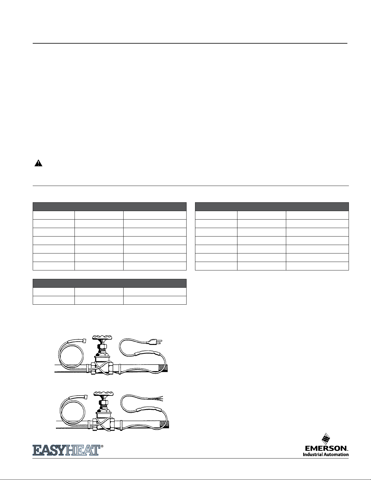
120 Volt Cable Selection Chart
Model No. Length in Ft. (m) Wattage @ 50°F (10°C)
PSR1006 6 (1.83) 30
PSR1012 12 (3.76) 60
PSR1018 18 (5.49) 90
PSR1024 24 (7.32) 120
PSR1050 50 (15.24) 250
PSR1075 75 (22.86) 375
PSR1100 100 (30.48) 500
with your local inspector for specic details.
2. These instructions must be retained and made available to the
user and transferred to future users.
3. Heating cables must not be energized in summer conditions; ensure
that all heating cables are de-energized during the summer.
4. It is recommended that the circuit supplying the heating cable
have ground fault protection; this is mandatory by electrical code
for some applications in many regions. Consult an electrical
inspector to determine the specic ground fault requirements for
your application prior to installation. If you are unsure that your
circuit has ground fault protection, consult an electrician.
5. Do not alter the length of the heating cable - cable is factory
sealed and alteration will result in risk of electrical re or shock.
6. Post warning labels (supplied with cable) to power supply disconnect
switch, circuit breaker panel, outdoor receptacle and any other
appropriate locations, as applicable. Also post labels along any pipe
(on outside of insulation) on which the cable is installed.
7. Do not bend cable to a diameter less than 5 times the cable
diameter.
8. Installing cable on a roof below 32°F (0°C) may damage the
shingle if it is brittle.
9. Minimum installation temperature for the heating cable set is
-30°C (-22°F).
240 Volt Cable Selection Chart
Model No. Length in Ft. (m) Wattage @ 50°F (10°C)
PSR2006 6 (1.83) 30
PSR2012 12 (3.76) 60
PSR2018 18 (5.49) 90
PSR2024 24 (7.32) 120
PSR2050 50 (15.24) 250
PSR2075 75 (22.86) 375
PSR2100 100 (30.48) 500
Breaker Size 120V Cable 240V Cable
15 Amp 125/115/100 250/225/205
20 Amp 170/150/135 335/300/270
Maximum total heater length (ft) / Circuit breaker size 20°F (-7°C)/0°F
(-20°C)/-20°F(-30°C) start-up
Pipe Freeze Protection
120V
240V
Planning
• Exposure to temperatures above 150°F (66°C) will shorten the
life of your cable. Before installing on hot water pipes, set the
water heater thermostat below 150°F (66°C).
• Remove any old heating tapes or insulation before installing
the new cable.
• Do not alter the length of the cable.
• Do not use thin 1/8" (3.18 mm) foil-backed foam insulation.
• If more than one heating cable is used on a single electrical
circuit please refer to the maximum heater length per circuit
breaker size chart. Check to make sure the total heating
cable length does not exceed the length specied in this
table.
Selection of heating cable. Select the appropriate cable length
from one of the two charts on next page. Cable may be up to
2 feet (60.96 cm) shorter than the pipe. Lengths assume lowest
ambient temperature is -20°F (-29°C), with a minimum of 1/2"
(12.7 mm) berglass insulation or equivalent. For protection to
-40°F (-40°C), use 1" (25.4 mm) berglass insulation. Note: Allow an
extra foot (30.48 cm) of heating cable for each valve.
©2012 EasyHeat www.easyheat.com 14022-001 Rev. 10
Page 2
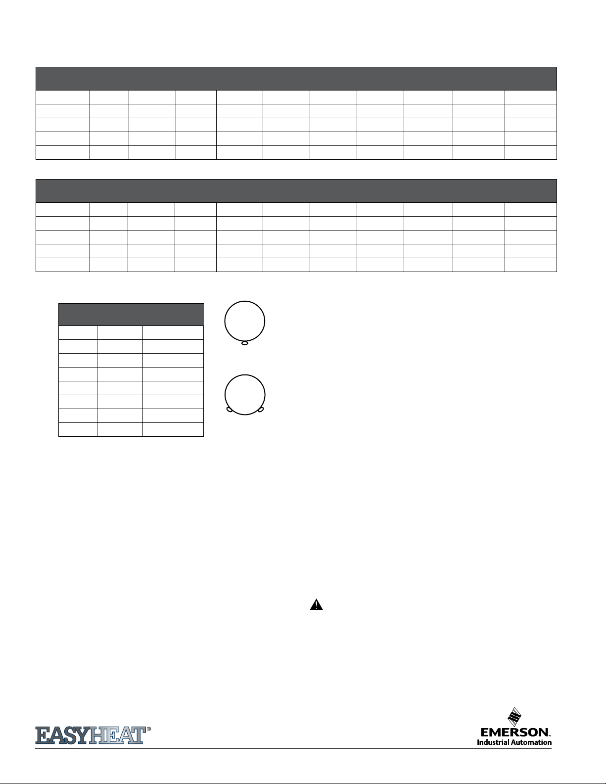
Cable Length Selection Chart
Ambient Temperature -20°F (-28.89°C), with 0.5" (12.7mm) Thick Fiberglass Insulation
METAL PIPE
Pipe Dia
0.5" (12.7mm) A A B B C C E F G
1.0" (25.4 mm) A A A B B C C E F G
1.5" (38.1 mm) A A A B B C D E F G
2.0" (50.8 mm) A B B C C D E F G H
2.5" (63.5 mm) A B B C C D E F G H
3'
.91m
4'-6'
1.2m-1.83m7'2.13m
8'-12'
2.44-3.66m
13'-14'
3.96-4.27m
15'-18'
4.57-5.49m
19'- 25'
5.79-7.62m
26'-50'
7.92-15.24m
51'-75'
15.54-22.86m
76'-100'
21.16-30.48m
PLASTIC PIPE
Pipe Dia
0.5" (12.7mm) A B B C D D E F G
1.0" (25.4 mm) A A B C C D E E F G
1.5" (38.1 mm) A B C D D E E F F H
2.0" (50.8 mm) A B C E E E E F G H
2.5" (63.5 mm) A B C E E E F F G H
3'
.91m
4'-6'
1.2m-1.83m7'2.13m
8'-12'
2.44-3.66m
13'-14'
3.96-4.27m
15'-18'
4.57-5.49m
19'- 25'
5.79-7.62m
26'-50'
7.92-15.24m
51'-75'
15.54-22.86m
76'-100'
21.16-30.48m
SELECTION CHART KEY
Model # # of Cables
A PSR (*)006 1 Cable
B PSR (*)012 1 Cable
C PSR (*)018 1 Cable
D PSR (*)024 1 Cable
E PSR (*)050 1 Cable
F PSR (*)075 1 Cable
G PSR (*)100 1 Cable
H PSR (*)100 2 Cable
Replace* with voltage code:
1 for 120V; 2 for 240V
Single Cable
Double Cable
Attaching heating cable to pipes
Wrap EasyHeat HCA (optional Application Tape) or nylon cable ties
at 6" (15.24 cm) intervals to secure the heating cable to the pipe.
• If the heating cable is the same length as the pipe, run it straight
along the bottom of the pipe. If two cables are required, position
them in the 4 and 8 o’clock positions.
• If the cable selected is exactly double the pipe length, apply a
single trace of cable straight along the pipe all the way to the
end, and loop back, applying cable straight along the pipe all
the way back to the starting point.
• If the cable selected is somewhat less than double the pipe
length, spiral the cable evenly along the entire length of pipe.
Protecting the system with thermal insulation
Before insulating, ensure that there is no damage, such as nicks or
cuts on the heating cables. Immediately cover the pipe, cables,
connections, valves and spigots with 1/2" (12.7 mm) to 1" (25.4 mm)
thick berglass insulation or equivalent. Do not leave the cables
exposed. Use re-resistant materials such as berglass wrap. Make
sure the insulation is waterproofed (with polyethylene or other
vapor barriers) in areas where water may come in contact with the
insulation.
Heating cable control options and power
connection
For 120 Volt cables, the heating cable can simply be plugged
into a ground fault protected electrical receptacle.
For 240 Volt cables, the cable is designed to be directly
connected into an appropriate electrical outlet box supplied
by ground fault protected circuit. Since it will be necessary
to remove power from the cable from time to time, such
as in summer, always connect the cable to an appropriate
double-pole electrical switch. If the heating cable is the only
load on the circuit, the branch circuit breaker may be used to
disconnect power from the cable (switch is not necessary).
In addition, a remote thermostat similar to EasyHeat model
C3RC can be used for 120 Volt or 240 Volt cables to reduce
energy consumption and extend the life of the cable. Consult
your local EasyHeat supplier or representative for other control
options.
Testing the system
Once the installation is complete, apply power to the heating
cable; wait about one hour, and then turn on a water tap
supplied by the protected pipe and test the temperature of
the water. It should feel warm almost immediately as the water
heated by the cable ows through the pipe.
Operation. Energize the cable/control upon the arrival of cold
weather in the fall and de-energize the cable in late spring.
Maintenance
Check cable each year for any damage before energizing the
heating cable. Check any ground fault protection device for
proper operation. Check pipe insulation and replace any that
may be loose or damaged. Do not operate the cable if any
damage is found.
www.easyheat.com
Page 3

Roof Deicing
Selection of heating cable. The total heating cable length for
deicing is determined by including all elements of the roof system
that need protection. Use Tables 1 and 2 to determine the total
length of cable. Usually one cable will be sufcient for both roof
and gutter areas. For larger installations, use separate cables for
roof area and gutter/downspout area.
Installation procedures
• Remove leaves, pine needles, or any combustible debris
from roof, gutters and downspouts before installing roof
deicing cable.
• Use ZH-C Roof Clips (sold separately) for attaching the heating
cable to the roof (shingle and metal roofs).
• For downspouts longer than 20 feet (6.10 m), use DSH
Downspout Hanger (sold separately) to support the heating
cable where it enters/exits a downspout.
One hanger is required for each downspout. Always loop the cable
down to the bottom of downspout and back up toward gutter,
clamping it into downspout hanger to prevent cable from being
damaged by drain/gutter edge. This also ensures that the cable tail is
secured on the roof. Cable to be linked to roof loop (see diagrams).
TYPICAL MEMBRANE ROOF
Valley
Roof Clips
Downward Slope
Drain
Heater Cable
Power Connection
Downward Slope
Table 1 Determination of total cable requirements
Model # # of Cables
Roof Edge From Table 2 based on eave overhang
Gutter 1' (30.48 cm) of cable/foot of gutter (if gutter is
wider than 6"(15.24cm), use 2 traces)
Downspout 2' (60.96 cm) of cable/foot of downspout–cable
is looped down and back
Roof Valley 6' (1.83m) of cable/valley - loop 3' (0.91m) up
valley and back
Dormer
1' (30.48 cm) of cable/foot of dormer perimeter
Perimeter
Table 2 Cable length factors vs. eave overhang
Eave
Overhang E
12"(30.48 cm) 18"(45.72 cm) 1.9 2.5
24"(60.96 cm) 30"(76.20 cm) 2.7 3.5
36"(0.91 m) 42"(1.07 m) 3.6 4.5
48"(1.22 m) 54"(1.37 m) 4.6 5.5
Cable length required = Length Factor × Roof Length (feet/m)
Notes:
* Typical shingle roof with sawtooth pattern. (See diagram)
** Typical metal roof with loop pattern spaced 24" (61 cm)
- for other spacing these factors will need to be adjusted
accordingly. (See diagram)
For other designs, contact EasyHeat.
Loop
Height H
Length Factor
Shingle Roof *
Length Factor
Metal Roof **
TYPICAL METAL ROOF (Separate cables shown for roof and gutter)
Roof Clip (ZH-C)
H
Heater Cable
Clip gutter cable to roof
cable to provide a path for
water to get to ground
End Seal
Must not be submerged
nor allowed to be at the
bottom end of a downspout.
DSH
Hanger Clamp
Weatherproof
outlet box
(by installer)
Drip Loop (Typ.)
Roof Clips
(@24" (60.96 cm)O.C.)
TYPICAL SHINGLE ROOF (Single cable shown for roof and gutter)
24"
Weatherproof Outlet
Box (by installer)
Drip Loop
Heater Cable
“H” loop height
“E” overhang distance from
roof edge to face of wall
overhang
END CIRCUIT
DOWNSPOUT
INSTALLATION
www.easyheat.com
MID CIRCUIT
DOWNSPOUT
INSTALLATION
Page 4

Heating cable control options and power
connection
For 120 Volt cables, the heating cable can be simply plugged
into a ground fault protected electrical receptacle, when icing
conditions are present on the roof. The (optional) EasyHeat RS-2
Roof Sentry (120 Volt) control can be used to automatically
ensure cables are energized only when icing conditions are
present on the roof, minimizing energy consumption and
extending cable life.
For 240 Volt cables, the cable is designed to be directly
connected into an appropriate electrical connection box.
Since it will be necessary to remove power from the cable from
time to time, such as in summer, always connect the cable to
an appropriate double-pole electrical switch. If the heating
cable is the only load on the circuit, the branch circuit breaker
may be used to disconnect power from the cable (switch is
not necessary). Several automatic controls are available from
EasyHeat.
Always connect a pilot light into the circuit of 240V cables to
indicate when the cables are energized.
Testing the system. Once the installation is complete, apply
power to the heating cable; the surface of the cable will feel
warm after about 15 minutes.
Operation
If no automatic controls are installed, energize the cable only
when icing conditions are present on the roof, and de-energize
when icing conditions are no longer present. For 120 Volt models
only, the power cord plug contains a pilot light indicating that
power is being applied to the cable. Ensure power is removed
from the cable/control in summer.
Maintenance
Check cable annually for any damage, such as nicks or cuts
possibly caused by animals or other activity on the roof. Check
any ground fault protection devices for proper operation.
Remove all debris (leaves, twigs, pine needles, etc.) from roof,
gutters and downspouts prior to energizing the roof cable. Do
not attempt to energize the roof cable if any of these problems
are discovered.
LIMITED WARRANTY AND LIABILITY
EasyHeat warrants that if there are any defects in material
or workmanship in this product during the rst twelve (12)
months after the date of its purchase, we will replace the
product with an equivalent model, not including any labor
or other installation costs.
Our obligation to replace the product as described above
is conditioned upon (a) the installation of the product
conforms to the specications set forth in our installation
instructions and (b) the product not having been damaged
by unrelated mechanical or electrical activities.
Product replacement as described above shall be your sole
and exclusive remedy for a breach of this warranty. This limited
warranty does not cover any service costs relating to repair
or replacement.
We shall not be liable for any incidental, special or
consequential damages as a result of any breach of this
warranty or otherwise, whether or not caused by negligence.
Some states do not allow the exclusion or limitation of
incidental or consequential damages, so the above limitation
or exclusion may not apply to you.
The warranty above is exclusive and makes no other warranties
with respect to description or quality of the product. No
afrmation of fact or promise made by us, by words or action,
shall constitute a warranty. If any model or sample was shown
to you, the model or sample was used merely to illustrate the
general type and quality of the goods and not to represent
that the goods would necessarily be of that type or nature. No
agent, employee or representative of ours has authority to bind
us to any afrmation, representation or warranty concerning
the goods sold unless such afrmation, representation or
warranty is specically incorporated by written agreement.
ANY IMPLIED WARRANTY OF MERCHANTABILITY OR FITNESS
FOR PARTICULAR PURPOSE THAT MAY ARISE IN CONNECTION
WITH THE SALE OF THIS PRODUCT SHALL BE LIMITED IN DURATION
TO TWELVE (12) MONTHS FROM THE DATE OF PURCHASE. WE
DISCLAIM ALL OTHER IMPLIED WARRANTIES, UNLESS WE ARE
PROHIBITED BY LAW FROM DOING SO, IN WHICH CASE ALL
SUCH IMPLIED WARRANTIES SHALL EXPIRE AT THE EARLIEST TIME
PERMITTED BY APPLICABLE LAW. Some states do not allow
limitations on how long an implied warranty lasts, so the above
limitation may not apply to you.
This warranty gives you specic legal rights, and you may also
have other rights which vary from state to state or province
to province.
To obtain a replacement under this warranty any inoperative
product or component must be returned, with proof of
purchase, to EasyHeat at the addresses noted herein. Buyer is
responsible for all costs incurred in removal and re-installation
of product and must pre-pay shipment to factory or point of
purchase.
In CANADA
99 Union St.
Elmira, Ont. N3B 3L7
Tel. (800) 794-3766 • Fax (800) 361-4574
In USA
2 Connecticut South Drive
East Granby, CT 06026
Tel. (800) 537-4732 • Fax (800) 541-7451
www.easyheat.com
 Loading...